EP2966252B1 - Fenster oder tür, insbesondere für ein niedrigenergie- oder passivhaus, mit einem profilelement mit geschäumtem kunststoff - Google Patents
Fenster oder tür, insbesondere für ein niedrigenergie- oder passivhaus, mit einem profilelement mit geschäumtem kunststoff Download PDFInfo
- Publication number
- EP2966252B1 EP2966252B1 EP15401061.5A EP15401061A EP2966252B1 EP 2966252 B1 EP2966252 B1 EP 2966252B1 EP 15401061 A EP15401061 A EP 15401061A EP 2966252 B1 EP2966252 B1 EP 2966252B1
- Authority
- EP
- European Patent Office
- Prior art keywords
- window
- door
- profile element
- profile
- accordance
- Prior art date
- Legal status (The legal status is an assumption and is not a legal conclusion. Google has not performed a legal analysis and makes no representation as to the accuracy of the status listed.)
- Active
Links
Images
Classifications
-
- E—FIXED CONSTRUCTIONS
- E06—DOORS, WINDOWS, SHUTTERS, OR ROLLER BLINDS IN GENERAL; LADDERS
- E06B—FIXED OR MOVABLE CLOSURES FOR OPENINGS IN BUILDINGS, VEHICLES, FENCES OR LIKE ENCLOSURES IN GENERAL, e.g. DOORS, WINDOWS, BLINDS, GATES
- E06B3/00—Window sashes, door leaves, or like elements for closing wall or like openings; Layout of fixed or moving closures, e.g. windows in wall or like openings; Features of rigidly-mounted outer frames relating to the mounting of wing frames
- E06B3/30—Coverings, e.g. protecting against weather, for decorative purposes
- E06B3/308—Wing frames covered on the outside by a rigidly-mounted outer frame
-
- E—FIXED CONSTRUCTIONS
- E06—DOORS, WINDOWS, SHUTTERS, OR ROLLER BLINDS IN GENERAL; LADDERS
- E06B—FIXED OR MOVABLE CLOSURES FOR OPENINGS IN BUILDINGS, VEHICLES, FENCES OR LIKE ENCLOSURES IN GENERAL, e.g. DOORS, WINDOWS, BLINDS, GATES
- E06B3/00—Window sashes, door leaves, or like elements for closing wall or like openings; Layout of fixed or moving closures, e.g. windows in wall or like openings; Features of rigidly-mounted outer frames relating to the mounting of wing frames
- E06B3/04—Wing frames not characterised by the manner of movement
- E06B3/263—Frames with special provision for insulation
- E06B3/26345—Frames with special provision for insulation for wooden or plastic section members
-
- E—FIXED CONSTRUCTIONS
- E06—DOORS, WINDOWS, SHUTTERS, OR ROLLER BLINDS IN GENERAL; LADDERS
- E06B—FIXED OR MOVABLE CLOSURES FOR OPENINGS IN BUILDINGS, VEHICLES, FENCES OR LIKE ENCLOSURES IN GENERAL, e.g. DOORS, WINDOWS, BLINDS, GATES
- E06B3/00—Window sashes, door leaves, or like elements for closing wall or like openings; Layout of fixed or moving closures, e.g. windows in wall or like openings; Features of rigidly-mounted outer frames relating to the mounting of wing frames
- E06B3/30—Coverings, e.g. protecting against weather, for decorative purposes
- E06B3/301—Coverings, e.g. protecting against weather, for decorative purposes consisting of prefabricated profiled members or glass
- E06B3/307—Coverings with special provisions for insulation, e.g. foam filled
-
- E—FIXED CONSTRUCTIONS
- E06—DOORS, WINDOWS, SHUTTERS, OR ROLLER BLINDS IN GENERAL; LADDERS
- E06B—FIXED OR MOVABLE CLOSURES FOR OPENINGS IN BUILDINGS, VEHICLES, FENCES OR LIKE ENCLOSURES IN GENERAL, e.g. DOORS, WINDOWS, BLINDS, GATES
- E06B7/00—Special arrangements or measures in connection with doors or windows
- E06B7/16—Sealing arrangements on wings or parts co-operating with the wings
- E06B7/22—Sealing arrangements on wings or parts co-operating with the wings by means of elastic edgings, e.g. elastic rubber tubes; by means of resilient edgings, e.g. felt or plush strips, resilient metal strips
- E06B7/23—Plastic, sponge rubber, or like strips or tubes
- E06B7/2305—Plastic, sponge rubber, or like strips or tubes with an integrally formed part for fixing the edging
- E06B7/2307—Plastic, sponge rubber, or like strips or tubes with an integrally formed part for fixing the edging with a single sealing-line or -plane between the wing and the part co-operating with the wing
- E06B7/2309—Plastic, sponge rubber, or like strips or tubes with an integrally formed part for fixing the edging with a single sealing-line or -plane between the wing and the part co-operating with the wing with a hollow sealing part
-
- E—FIXED CONSTRUCTIONS
- E06—DOORS, WINDOWS, SHUTTERS, OR ROLLER BLINDS IN GENERAL; LADDERS
- E06B—FIXED OR MOVABLE CLOSURES FOR OPENINGS IN BUILDINGS, VEHICLES, FENCES OR LIKE ENCLOSURES IN GENERAL, e.g. DOORS, WINDOWS, BLINDS, GATES
- E06B3/00—Window sashes, door leaves, or like elements for closing wall or like openings; Layout of fixed or moving closures, e.g. windows in wall or like openings; Features of rigidly-mounted outer frames relating to the mounting of wing frames
- E06B3/04—Wing frames not characterised by the manner of movement
- E06B3/06—Single frames
- E06B3/08—Constructions depending on the use of specified materials
- E06B3/10—Constructions depending on the use of specified materials of wood
-
- E—FIXED CONSTRUCTIONS
- E06—DOORS, WINDOWS, SHUTTERS, OR ROLLER BLINDS IN GENERAL; LADDERS
- E06B—FIXED OR MOVABLE CLOSURES FOR OPENINGS IN BUILDINGS, VEHICLES, FENCES OR LIKE ENCLOSURES IN GENERAL, e.g. DOORS, WINDOWS, BLINDS, GATES
- E06B3/00—Window sashes, door leaves, or like elements for closing wall or like openings; Layout of fixed or moving closures, e.g. windows in wall or like openings; Features of rigidly-mounted outer frames relating to the mounting of wing frames
- E06B3/30—Coverings, e.g. protecting against weather, for decorative purposes
- E06B3/301—Coverings, e.g. protecting against weather, for decorative purposes consisting of prefabricated profiled members or glass
- E06B3/302—Covering wooden frames with metal or plastic profiled members
-
- Y—GENERAL TAGGING OF NEW TECHNOLOGICAL DEVELOPMENTS; GENERAL TAGGING OF CROSS-SECTIONAL TECHNOLOGIES SPANNING OVER SEVERAL SECTIONS OF THE IPC; TECHNICAL SUBJECTS COVERED BY FORMER USPC CROSS-REFERENCE ART COLLECTIONS [XRACs] AND DIGESTS
- Y02—TECHNOLOGIES OR APPLICATIONS FOR MITIGATION OR ADAPTATION AGAINST CLIMATE CHANGE
- Y02A—TECHNOLOGIES FOR ADAPTATION TO CLIMATE CHANGE
- Y02A30/00—Adapting or protecting infrastructure or their operation
- Y02A30/24—Structural elements or technologies for improving thermal insulation
-
- Y—GENERAL TAGGING OF NEW TECHNOLOGICAL DEVELOPMENTS; GENERAL TAGGING OF CROSS-SECTIONAL TECHNOLOGIES SPANNING OVER SEVERAL SECTIONS OF THE IPC; TECHNICAL SUBJECTS COVERED BY FORMER USPC CROSS-REFERENCE ART COLLECTIONS [XRACs] AND DIGESTS
- Y02—TECHNOLOGIES OR APPLICATIONS FOR MITIGATION OR ADAPTATION AGAINST CLIMATE CHANGE
- Y02B—CLIMATE CHANGE MITIGATION TECHNOLOGIES RELATED TO BUILDINGS, e.g. HOUSING, HOUSE APPLIANCES OR RELATED END-USER APPLICATIONS
- Y02B80/00—Architectural or constructional elements improving the thermal performance of buildings
Definitions
- the invention relates to a window or a door with a profile element, in particular in the form of an adapter profile, with foamed plastic.
- the window or the door is particularly suitable for a low-energy house or a passive house.
- Windows and doors made of wood, plastic, metal such as aluminum or a combination of these materials are known.
- windows and doors for low-energy houses or so-called passive houses ie houses with a heating requirement of a maximum of 15 kWh / (m 2 a)
- passive houses ie houses with a heating requirement of a maximum of 15 kWh / (m 2 a)
- the heat transfer values of such windows or doors are increasingly determined by the profiles of the windows or doors and not more as in the previous extent of the glazing or door panels.
- EP 2 706 184 A1 shows a window for a low energy house or a passive house with a window profile element, another profile element, which can also be referred to as an adapter profile, and a glazing component.
- the glazing component is connected to the further profile element and the further profile element to the window profile element. Furthermore, the glazing component is glued to the further profile element in at least one gluing area.
- the further profile element may be a fiberglass profile, a screen printing plate or multiplex plate or a corresponding profile, a polycarbonate profile, a PVC profile or a polyamide profile.
- FR 2 971 808 A1 shows a window according to the preamble of claim 1.
- Object of the present invention was to provide a window or a door with further improved heat transfer values, especially in the frame area.
- the invention relates to a window or a door according to claim 1.
- the invention can basically be used equally in a window as in a door, wherein the window frame of the window corresponds to the door frame or the Moszargenprofil the door, and wherein the sash of the window corresponds to the door leaf or the door leaf profile of the door.
- the following also applies to a window described in a similar manner for a door.
- the foamed plastic has a thermal conductivity in a range of 0.048 to 0.07 W / mK.
- the sealing profile has a boundary wall which extends along an edge of the further profile element to a pane of the glazing component.
- the adhesive region is partially bounded by an end seal, wherein the end seal is connected to the further profile element and along an edge of the further profile element to a pane of the glazing component ( 40).
- this further seal is preferably a seal made of polypropylene or polypropylene foam.
- the window according to the invention is a window which has a U frame value laterally or above according to EN ISO 10077-2 of less than 0.61 W / (m 2 K).
- the inventive design of the other profile element or adapter profile with or from the foamed plastic is a significant improvement of the U frame value according to EN ISO 10077-22 compared to an analog window with a corresponding profile element made of conventional plastic, fiberglass, a screen printing plate or a multiplex plate reached.
- the further profile element is characterized by a low thermal conductivity with high strength and stability at relatively low weight.
- the other profile element or the corresponding starting material is relatively inexpensive and can be profiled and processed in a simple manner by means of established techniques such as sawing, cutting, milling and grinding.
- the further profile element in the form of an extruded and profiled PVC foam sheet of the foamed plastic or an extruded and profiled integral foam sheet of the foamed plastic with an at least partially smooth homogeneous surface, the further profile element can be particularly easily and reliably glued to the glazing component.
- the adhesive area is advantageously limited by the further profile element, the glazing component, a cavity between the further profile element and the glazing component and one or more sealing profiles.
- the location of the adhesive region is at least three sides defined precisely and its thickness is largely predetermined or adjustable over the dimensions of the sealing profile. This leads to a high quality bond with uniform thickness of the adhesive layer.
- the adhesive area is provided in a corner or vicinity of a corner, for example, L-shaped in a corner of the corner, wherein the corner of only the further profile element or further profile element and the frame profile is formed.
- the adhesive area is provided only on the inside of the glazing component, in particular L-shaped in the corner between the glazing component and the further profile element or L-shaped in the corner between the glazing component on the one hand and the further profile element and the frame profile on the other ,
- the window or the door according to the invention is preferably a window or a door for a low-energy house or a passive house, ie in the case of the window, a window according to EN ISO 10077-2 and based on a window test size of 1230 x 1480 mm, a heat transfer window (U window ) of ⁇ 0.69 W / (m 2 K), in particular ⁇ 0.64 W / (m 2 K) or, for example, 0.63 W / (m 2 K), and a heat transfer frame (U frame ) side and top of ⁇ 0.65 W / (m 2 K), in particular ⁇ 0.63 W / (m 2 K) or for example 0.61 W / (m 2 K).
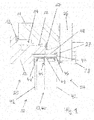
- FIG. 1 a first embodiment of the invention in the form of a section through a portion of a window
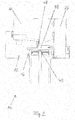
- FIG. 2 shows an alternative embodiment of the invention in the form of a section through a part of a window.
- FIG. 2 illustrates an exemplary embodiment of the invention in the form of a window 10 for a low-energy or passive house, which according to EN ISO 10077-2 and based on a window test size of 1230 ⁇ 1480 mm and based on a window test size of 1230 ⁇ 1480 mm, a heat transfer window (U window ) ⁇ 0.64 W / (m 2 K) or, for example, 0.63 W / (m 2 K) and a heat transfer frame (U frame ) laterally and upward of ⁇ 0.63 W / (m 2 K) or, for example, 0, 61 W / (m 2 K).
- a heat transfer window U window
- U frame ⁇ 0.64 W / (m 2 K) or, for example, 0.63 W / (m 2 K
- U frame laterally and upward of ⁇ 0.63 W / (m 2 K) or, for example, 0, 61 W / (m 2 K).
- FIG. 1 shows a portion of the window 10 in section with a frame profile 11, a sash profile 12, a glazing 13 and a glazing component 40 and a chamber 14 between the frame profile 11 and the sash profile 12.
- the chamber 14 is in this embodiment by means of a first seal 47th and a second seal 19 between the frame profile 11 and the casement profile 12 is closed.
- the glazing component 40 is connected to the sash frame profile 12 via a further profile element 48, which may also be referred to as an adapter profile element.
- the further profile element 48 is formed in the illustrated example of a foamed plastic.
- the foamed plastic has a thermal conductivity in a range of 0.04 to 0.08 W / mK or in a range of 0.048 to 0.07 W / mK, for example, about 0.05 W / mK.
- the foamed plastic is preferably polyvinyl chloride (PVC), ie the further profile element 48 consists in the illustrated example of a PVC foam sheet profile of the foamed plastic, in particular an extruded and profiled PVC foam sheet of the foamed plastic.
- the PVC foam sheet profile is preferably a profiled extruded PVC integral foam sheet of the foamed plastic.
- Such integral PVC foam panels which can be produced by the Celuka process, for example, by the company.
- Veka AG Senden Horst, under the name "Vekaplan S” in thicknesses of 8 to 30 mm, see http: //www.vekaplan. de / vekaplan / divers / en / vekaplan_s_communigenschaften.htm, distributed.
- Vekaplan S in thicknesses of 8 to 30 mm
- such integral PVC foam panels are also from the company. Profine GmbH, Pirmasens, sold under the name "K ⁇ MACEL®” in thicknesses of 4 to 30 mm, see http://komasheets.com/ employment/koemacel/technische- Scheme_5.
- thicknesses of 8-13 mm are used for the further profile element 48 here.
- the profiled extruded PVC integral foam sheets used preferably have, at least in some areas, a smooth, homogeneous surface.
- the Shore hardness D according to DIN 53505 of the foamed plastic used or the profiled extruded PVC integral foam sheets used is preferably in a range of 50-80, more preferably 72 to 78 or about 75.
- the modulus of elasticity according to ISO 527-2 used foamed plastic or used profiled extruded PVC integral foam sheets is preferably in a range of 700-1200 MPa as at about 800 MPa or at about 1050 MPa.
- the chamber 14 is closed by means of the second seal 19 between the frame profile 11 and the casement profile 12.
- the seals 47, 19 are preferably conventional rubber seals for windows of the type described in US Pat FIG. 1 shown in more detail.
- the frame profile 11 and the sash profile 12 may be solid wood profiles.
- the frame profile 11 and the sash profile 12 can also be made of a laminated veneer lumber, d. H. for example, from about 3 mm thick individual peeled veneers made of softwood such as spruce.
- the covering layer 27 provided on the side of the insulating board 26 facing the window frame profile 11 is connected to the window frame profile 11, preferably glued again.
- the FIG. 1 further shows how the further profile element 48 holds the glazing component 40.
- the glazing component 40 is designed in a manner known per se as a multi-pane insulating glass component with three or more panes 42 and has an edge connection 41.
- the inner cavities of the glazing component 40 are filled, for example, with argon.
- a further seal 43 in particular a further seal 43 made of polypropylene or polypropylene foam, is preferably provided in regions.
- the glazing component 40 is adhesively bonded to the further profile element 48 in one or more adhesive areas.
- the adhesive is preferably a 2-component adhesive, especially based on silicone.
- the further profile element 48 is formed as shown substantially L-shaped or staircase-shaped.
- the further seal 43 is preferably provided in the middle approximately between the outer panes 42 of the glazing component 40 or approximately centrally but in the direction of the casement profile 12 (or generally the window profile element or door profile element) between the outer panes 42 of the glazing component 40.
- the casement profile 12 (or more generally the window profile element or the door profile element) has, in the illustrated example, a groove for receiving a corresponding area of the further profile element 48. This facilitates precise production and positioning of the further profile element 48 with the glazing component 40 relative to the sash profile 12 during the bonding.
- the end seal 44 is preferably a relatively hard end seal 44 having a hardness in a range of 70 to 90 Shore A, in particular 80 Shore A. It is connected to the further profile element 48 and extends over the interface between the glazing component 40 and the further profile element 48 out in the disk 42 of the glazing component 40 and touches there. For this purpose, the end seal 44 has a sealing lip there.
- the end seal 44 is preferably made of rubber and preferably anchored in a groove of the further profile element 20.
- the two panes 42 of the glazing component 40 and the edge assembly 41 enclose a cavity, which is filled in particular with a noble gas such as argon (or possibly also krypton).
- a noble gas such as argon (or possibly also krypton).
- the glazing component 40 has at least three panes 42, which with the edge seal 41 at least two separate, in particular filled with a noble gas such as argon Include cavities.
- the glazing component 40 is connected to the further profile element 48 in the region of the edge bond 41.
- the third seal 47 in Figure 4 is anchored in the frame profile 11 and preferably mounted so that it has no contact with the further profile element 48.
- an adhesive region 46 is provided, which is located on the outside 24 facing side of the further profile element 48 in the corner formed by the glazing 13, the end seal 44 and the other profile element 48.
- This adhesive region 46 is not formed circumferentially around the corner and is preferably also not in contact with the sealing gasket 44, ie the sealing region preferably connects only the glazing 13 with the further profile element 48.
- an adhesive such as a 2- Silicone-based component adhesives are used.
- the adhesive region 46 can in FIG.
- a further adhesive region may be provided on the side of the further profile element 48 facing the inner side 25 in the corner formed by the glazing 13, the casement profile 12 and the further profile element 48 or in the vicinity of this corner.
- an inner seal 44 ' located on the inside 25 between the glazing 13 and the sash profile 12, an inner seal 44 ', which is inserted in a groove in the sash profile 12 and preferably not with the other profile element 48 in contact. This inner seal 44 'seals the casement profile 12 from the glazing 13.
- FIG. 2 illustrates an alternative embodiment of a window 10, this window being analogous in many ways to FIG. 1 is constructed so that here only the differences between the embodiment according to FIG. 1 and the embodiment according to FIG. 2 should be explained and in the FIG. 1 in FIG. 2 For the sake of clarity, some are not drawn again, if they designate analog components.
- the third seal 47 is provided in regions between the sash frame profile 12, and the further profile element 48 and in contact with both.
- the gluing area 46 is now located between the glazing 13 and the further profile element 48 or between the glazing 13, the further profile element 48 and the sash frame profile 12.
- the further profile element 48 in the example of FIG. 2 is made of a foamed plastic with a thermal conductivity of 0.11 W / mK.
- the foamed plastic has a thermal conductivity in a range of 0.04 to 0.08 W / mK or in a range of 0.048 to 0.07 W / mK, for example, about 0.05 W / mK.
- the foamed plastic is preferably polyvinyl chloride (PVC), ie the further profile element 48 consists of a PVC foam sheet profile of the foamed plastic, in particular an extruded and profiled PVC foam sheet of the foamed plastic.
- the PVC foam sheet profile is preferably a profiled extruded PVC integral foam sheet of the foamed plastic, as sold under the name "Vekaplan S" or under the name "K ⁇ MACEL®”. Preferably, thicknesses of 8-13 mm are used for the further profile element 20 here.
- the profiled extruded PVC integral foam sheets used preferably have, at least in some areas, a smooth, homogeneous surface.
- the Shore hardness D according to DIN 53505 of the foamed plastic used or the profiled extruded PVC integral foam sheets used is preferably in a range of 50 to 80, more preferably 72 to 78 or about 75.
- the modulus of elasticity according to ISO 5272 of the foamed plastic used or the profiled extruded PVC integral foam sheets used is preferably in a range of 700-1200 MPa as at about 800 MPa or at about 1050 MPa.
Landscapes
- Engineering & Computer Science (AREA)
- Civil Engineering (AREA)
- Structural Engineering (AREA)
- Securing Of Glass Panes Or The Like (AREA)
Description
- Die Erfindung betrifft ein Fenster oder eine Tür mit einem Profilelement, insbesondere in Form eines Adapterprofils, mit geschäumtem Kunststoff. Das Fenster bzw. die Tür eignet sich besonders für ein Niedrigenergiehaus oder ein Passivhaus.
- Fenster und Türen aus Holz, Kunststoff, Metall wie Aluminium oder aus einer Kombination dieser Materialien sind bekannt. Insbesondere sind auch Fenster und Türen für Niedrigenergiehäuser oder sogenannte Passivhäuser, d. h. Häuser mit einem Heizwärmebedarf von maximal 15 kWh/(m2a), bekannt, die sich durch besonders geringe Wärmedurchgangswerte auszeichnen. In dieser Hinsicht sei beispielsweise auf die Produkte der Anmelderin verwiesen, die u. a. auf der Internetseite www.enersign.com beschrieben werden. Die Wärmedurchgangswerte solcher Fenster bzw. Türen, insbesondere solcher, die für ein Gebäude vorgesehen sind, das die Anforderungen an ein KfW-Effizienzhaus 40 (EnEV 2009) oder besser erfüllen soll, werden zunehmend durch die Profile der Fenster bzw. Türen bestimmt und nicht mehr wie im bisherigen Ausmaß von den Verglasungen oder Türfüllungen.
-
EP 2 706 184 A1 zeigt ein Fenster für ein Niedrigenergiehaus oder ein Passivhaus mit einem Fensterprofilelement, einem weiteren Profilelement, das auch als Adapterprofil bezeichnet werden kann, und einem Verglasungsbauelement. Das Verglasungsbauelement ist mit dem weiteren Profilelement und das weitere Profilelement mit dem Fensterprofilelement verbunden. Weiter ist das Verglasungsbauelement mit dem weiteren Profilelement in mindestens einem Klebebereich verklebt. Das weitere Profilelement kann ein Fiberglasprofil, eine Siebdruckplatte oder Multiplexplatte bzw. ein entsprechendes Profil, ein Polycarbonatprofil, ein PVC-Profil oder ein Polyamidprofil sein. -
FR 2 971 808 A1 - Aufgabe der vorliegenden Erfindung war die Bereitstellung eines Fensters oder einer Tür mit weiter verbesserten Wärmedurchgangswerten vor allem im Rahmenbereich.
- Die Erfindung betrifft ein Fenster oder eine Tür gemäß Anspruch 1.
- Vorteilhafte Weiterbildungen der Erfindung sind Gegenstand der Unteransprüche.
- Die Erfindung kann grundsätzlich gleichermaßen bei einem Fenster wie bei einer Tür eingesetzt werden, wobei dem Blendrahmen des Fensters die Türzarge oder das Türzargenprofil der Tür entspricht, und wobei dem Flügelrahmen des Fensters das Türblatt oder das Türflügelprofil der Tür entspricht. Insofern gilt das nachfolgend für ein Fenster beschriebene in analoger Weise auch für eine Tür.
- In einer bevorzugten Ausführungsform der Erfindung ist bei dem erfindungsgemäßen Fenster oder der erfindungsgemäßen Tür vorgesehen, dass der geschäumte Kunststoff eine Wärmeleitfähigkeit in einem Bereich von 0,048 bis 0,07 W/mK aufweist.
- In einer bevorzugten Ausführungsform der Erfindung ist bei dem erfindungsgemäßen Fenster oder der erfindungsgemäßen Tür vorgesehen, dass das Dichtungsprofil eine Begrenzungswand aufweist, die sich entlang eines Randes des weiteren Profilelementes zu einer Scheibe des Verglasungsbauelementes erstreckt.
- In einer bevorzugten Ausführungsform der Erfindung ist bei dem erfindungsgemäßen Fenster oder der erfindungsgemäßen Tür vorgesehen, dass der Klebebereich bereichsweise von einer Abschlussdichtung begrenzt wird, wobei die Abschlussdichtung mit dem weiteren Profilelement verbunden ist und sich entlang eines Randes des weiteren Profilelementes zu einer Scheibe des Verglasungsbauelementes (40) erstreckt.
- In einer bevorzugten Ausführungsform der Erfindung ist bei dem erfindungsgemäßen Fenster oder der erfindungsgemäßen Tür vorgesehen, dass bereichsweise zwischen dem weiteren Profilelement und dem Verglasungsbauelement eine weitere Dichtung vorgesehen ist. Diese weitere Dichtung ist vorzugsweise eine Dichtung aus Polypropylen oder Polypropylenschaumstoff ist.
- In einer bevorzugten Ausführungsform der Erfindung ist das erfindungsgemäße Fenster ein Fenster, das einen Uframe-Wert seitlich bzw. oben gemäß EN ISO 10077-2 von weniger als 0,61 W/(m2K) aufweist.
- Durch die erfindungsgemäße Ausbildung des weiteren Profilelements bzw. Adapterprofils mit oder aus dem geschäumten Kunststoff wird eine deutliche Verbesserung des Uframe-Wertes gemäß EN ISO 10077-22 gegenüber einem analogen Fenster mit einem entsprechenden Profilelement aus herkömmlichem Kunststoff, Fiberglas, einer Siebdruckplatte oder einer Multiplexplatte erreicht. Dabei zeichnet sich das weitere Profilelement durch eine niedrige Wärmeleitfähigkeit bei hoher Festigkeit und Stabilität bei vergleichsweise geringem Gewicht aus. Daneben ist das weitere Profilelement bzw. das entsprechende Ausgangsmaterial vergleichsweise kostengünstig und mittels etablierter Techniken wie sägen, schneiden, fräsen und schleifen in einfacher Weise profilierbar und bearbeitbar.
- Bei einem weiteren Profilelement in Form einer extrudierten und profilierten PVC-Schaumplatte aus dem geschäumten Kunststoff bzw. einer extrudierten und profilierten Integralschaumplatte aus dem geschäumten Kunststoff mit einer zumindest bereichsweise glatten homogenen Oberfläche kann das weitere Profilelement besonders einfach und zuverlässig mit dem Verglasungsbauelement verklebt werden.
- Der Klebebereich ist vorteilhaft von dem weiteren Profilelement, dem Verglasungsbauelement, einem Hohlraum zwischen dem weiteren Profilelement und dem Verglasungsbauelement und einem oder mehreren Dichtungsprofilen begrenzt. Dadurch ist der Ort des Klebebereiches zumindest dreiseitig genau definiert und auch seine Dicke ist weitgehend vorgegeben bzw. über die Dimensionierung des Dichtungsprofils einstellbar. Dies führt zu einer qualitativ hochwertigen Verklebung mit gleichmäßiger Dicke der Klebeschicht. Vorzugsweise ist der Klebebereich in einer Ecke oder einer Umgebung einer Ecke, beispielsweise L-förmig in einer Ecke des vorgesehen, wobei die Ecke nur von dem weiteren Profilelement oder dem weiteren Profilelement und dem Rahmenprofil gebildet wird. In einer anderen Ausführungsform ist der Klebebereich ist nur auf der Innenseite des Verglasungsbauelementes vorgesehen, insbesondere L-förmig in der Ecke zwischen dem Verglasungsbauelement und dem weiterem Profilelement bzw. L-förmig in der Ecke zwischen dem Verglasungsbauelement einerseits und dem weiterem Profilelement und dem Rahmenprofil andererseits.
- Das erfindungsgemäße Fenster bzw. die erfindungsgemäße Tür ist vorzugsweise ein Fenster oder eine Tür für ein Niedrigenergiehaus oder ein Passivhaus, d. h. im Fall des Fensters ein Fenster, das gemäß EN ISO 10077-2 und bezogen auf eine Fensterprüfgröße von 1230 x 1480 mm einen Wärmedurchgang Fenster (Uwindow) von < 0,69 W/(m2K), insbesondere < 0,64 W/(m2K) oder beispielsweise 0,63 W/(m2K), und einen Wärmedurchgang Rahmen (Uframe) seitlich und oben von < 0,65 W/(m2K), insbesondere < 0,63 W/(m2K) oder beispielsweise 0,61 W/(m2K) hat.
- Die Erfindung wird anhand der Zeichnungen und der nachfolgend beschriebenen Ausführungsbeispiele näher erläutert. Es zeigt
Figur 1 ein erstes Ausführungsbeispiel der Erfindung in Form eines Schnittes durch einen Teil eines Fensters undFigur 2 zeigt ein alternatives Ausführungsbeispiel der Erfindung in Form eines Schnittes durch einen Teil eines Fensters. - Die
Figur 1 erläutert ein Ausführungsbeispiel der Erfindung in Form eines Fensters 10 für ein Niedrigenergie oder Passivhaus, das gemäß EN ISO 10077-2 und bezogen auf eine Fensterprüfgröße von 1230 x 1480 mm und bezogen auf eine Fensterprüfgröße von 1230 x 1480 mm einen Wärmedurchgang Fenster (Uwindow) < 0,64 W/(m2K) oder beispielsweise 0,63 W/(m2K) und einen Wärmedurchgang Rahmen (Uframe) seitlich und oben von < 0,63 W/(m2K) oder beispielsweise 0,61 W/(m2K) hat. DieFigur 1 zeigt einen Teilbereich des Fensters 10 im Schnitt mit einem Blendrahmenprofil 11, einem Flügelrahmenprofil 12, einer Verglasung 13 bzw. einem Verglasungsbauelement 40 und einer Kammer 14 zwischen dem Blendrahmenprofil 11 und dem Flügelrahmenprofil 12. Die Kammer 14 ist in diesem Ausführungsbeispiel mittels einer ersten Dichtung 47 und einer zweiten Dichtung 19 zwischen dem Blendrahmenprofil 11 und dem Flügelrahmenprofil 12 geschlossen. Weiter ist das Verglasungsbauelement 40 über ein weiteres Profilelement 48, das auch als Adapterprofilelement bezeichnet werden kann, mit dem Flügelrahmenprofil 12 verbunden. Das weitere Profilelement 48 ist im erläuterten Beispiel aus einem geschäumten Kunststoff ausgebildet. Der geschäumte Kunststoff hat eine Wärmeleitfähigkeit in einem Bereich von 0,04 bis 0,08 W/mK oder in einem Bereich von 0,048 bis 0,07 W/mK, beispielsweise ca. 0,05 W/mK. Der geschäumte Kunststoff ist bevorzugt Polyvinylchlorid (PVC), d. h. das weitere Profilelement 48 besteht im erläuterten Beispiel aus einem PVC-Schaumplattenprofil aus dem geschäumten Kunststoff, insbesondere einer extrudierten und profilierten PVC-Schaumplatte aus dem geschäumten Kunststoff. Das PVC-Schaumplattenprofil ist vorzugsweise eine profilierte extrudierte PVC-Integralschaumplatte aus dem geschäumten Kunststoff. Derartige PVC-Integralschaumplatten, die nach dem Celuka-Verfahren hergestellt werden können, werden beispielsweise von der Fa. Veka AG, Sendenhorst, unter der Bezeichnung "Vekaplan S" in Stärken von 8 bis 30 mm, siehe http://www.vekaplan.de/vekaplan/divers/de/vekaplan_s_produkteigenschaften.htm, vertrieben. Daneben werden derartige PVC-Integralschaumplatten auch von der Fa. profine GmbH, Pirmasens, unter der Bezeichnung "KÖMACEL®" in Stärken von 4 bis 30 mm, siehe http://komasheets.com/produkte/koemacel/technische-daten_5, vertrieben. Bevorzugt werden hier Stärken von 8-13 mm für das weitere Profilelement 48 verwendet. Die verwendeten profilierten extrudierten PVC-Integralschaumplatten weisen vorzugsweise zumindest bereichsweise eine glatte homogene Oberfläche auf. Die Shore-Härte D nach DIN 53505 des verwendeten geschäumten Kunststoffs bzw. der verwendeten profilierten extrudierten PVC-Integralschaumplatten liegt vorzugsweise in einem Bereich von 50-80, besonders bevorzugt 72 bis 78 oder ca. 75. Der Elastizitätsmodul nach ISO 527-2 des verwendeten geschäumten Kunststoffs bzw. der verwendeten profilierten extrudierten PVC-Integralschaumplatten liegt vorzugsweise in einem Bereich von 700-1200 MPa wie bei ca. 800 MPa oder bei ca. 1050 MPa. - Auf der Innenseite 25 des Fensters 10 ist die Kammer 14 mittels der zweiten Dichtung 19 zwischen dem Blendrahmenprofil 11 und dem Flügelrahmenprofil 12 geschlossen. Die Dichtungen 47, 19 sind vorzugsweise übliche Gummidichtungen für Fenster des erläuterten Typs in der in
Figur 1 näher gezeigten Form. - Das Blendrahmenprofil 11 und das Flügelrahmenprofil 12 können Massivholzprofile sein. Weiter können das Blendrahmenprofil 11 und das Flügelrahmenprofil 12 auch aus einem Furnierschichtholz, d. h. beispielsweise aus ca. 3 mm dicken einzelnen Schälfurnieren aus Nadelholz wie Fichte ausgebildet sein.
- Auf der Außenseite 24 des Fensters 10 ist im erläuterten Beispiel eine ca. 27 mm dicke Dämmplatte 26 aus XPS, d. h. expandiertem Polystyrol, vorgesehen, die beiderseits mit einer ca. 1 mm bis 3 mm dünnen Deckschicht 27 insbesondere aus Fiberglas versehen, vorzugsweise verklebt ist, und die weiter mit einem vorzugsweise ebenfalls aufgeklebten Aluminiumprofil oder allgemeiner einem Abdeckprofil 28 (z. B. auch aus Kunststoff oder Kupfer) versehen ist. Die auf der dem Blendrahmenprofil 11 zugewandten Seite der Dämmplatte 26 vorgesehene Deckschicht 27 ist mit dem Blendrahmenprofil 11 verbunden, vorzugsweise erneut verklebt.
- Die
Figur 1 zeigt weiter, wie das weitere Profilelement 48 das Verglasungsbauelement 40 hält. Das Verglasungsbauelement 40 ist in an sich bekannter Weise als Mehrscheibenisolierglasbauelement mit drei oder mehr Scheiben 42 ausgebildet und weist einen Randverbund 41 auf. Die inneren Hohlräume des Verglasungsbauelementes 40 sind beispielsweise mit Argon gefüllt. Zwischen dem Verglasungsbauelement 40 und dem weiteren Profilelement 48 ist vorzugsweise bereichsweise eine weitere Dichtung 43, insbesondere eine weitere Dichtung 43 aus Polypropylen oder Polypropylenschaumstoff vorgesehen. Das Verglasungsbauelement 40 ist mit dem weiteren Profilelement 48 in einem oder mehreren Klebebereichen verklebt. Der Kleber ist vorzugsweise ein 2-Komponentenkleber, insbesondere auf Silikonbasis. Auf der Außenseite 24 des Fensters 10, wird der Übergangsbereich von dem weiteren Profilelement 48 zu dem Verglasungsbauelement 40 mit Hilfe einer Abschlussdichtung 44 abgedichtet, die an ihrem Ende eine Lippe aufweist, die mit der Scheibe 42 in Kontakt ist. - Das weitere Profilelement 48 ist wie gezeigt als im Wesentlichen L-förmig oder treppenstufenförmig ausgebildet.
- Die weitere Dichtung 43 ist im Schnitt vorzugsweise in etwa mittig zwischen den äußeren Scheiben 42 des Verglasungsbauelementes 40 oder in etwa mittig aber in Richtung auf das Flügelrahmenprofil 12 (oder allgemein das Fensterprofilelement oder das Türprofilelement) versetzt zwischen den äußeren Scheiben 42 des Verglasungsbauelementes 40 vorgesehen. Das Flügelrahmenprofil 12 (oder allgemeiner das Fensterprofilelement oder das Türprofilelement) weist im erläuterten Beispiel eine Nut zur Aufnahme eines entsprechenden Bereiches des weiteren Profilelementes 48 auf. Dies erleichtert eine präzise Fertigung und Positionierung des weiteren Profilelementes 48 mit dem Verglasungsbauelement 40 relativ zu dem Flügelrahmenprofil 12 bei der Verklebung.
- Die Abschlussdichtung 44 ist vorzugsweise eine relativ harte Abschlussdichtung 44 mit einer Härte in einem Bereich von 70 bis 90 Shore A, insbesondere 80 Shore A. Sie ist mit dem weiteren Profilelement 48 verbunden und erstreckt sich über die Grenzfläche zwischen dem Verglasungsbauelement 40 und dem weiterem Profilelement 48 hinaus in die Scheibe 42 des Verglasungsbauelementes 40 und berührt diese dort. Dazu weist die Abschlussdichtung 44 dort ein Dichtlippe auf. Die Abschlussdichtung 44 ist vorzugsweise aus Gummi ausgebildet und vorzugsweise in einer Nut des weiteren Profilelements 20 verankert.
- Die beiden Scheiben 42 des Verglasungsbauelementes 40 und der Randverbund 41 schließen einen Hohlraum ein, der insbesondere mit einem Edelgas wie Argon (oder gegebenenfalls auch Krypton) gefüllt ist. Vorzugsweise weist das Verglasungsbauelement 40 mindestens drei Scheiben 42 auf, die mit dem Randverbund 41 mindestens zwei getrennte, insbesondere mit einem Edelgas wie Argon gefüllte Hohlräume einschließen. Das Verglasungsbauelement 40 ist im Bereich des Randverbundes 41 mit dem weiteren Profilelement 48 verbunden.
- Die dritte Dichtung 47 in Figur 4 ist in dem Blendrahmenprofil 11 verankert und vorzugsweise so angebracht, dass sie keinen Kontakt zu dem weiteren Profilelement 48 hat. Gemäß
Figur 1 ist ein Klebebereich 46 vorgesehen, der sich auf der der Außenseite 24 zugewandten Seite des weiteren Profilelements 48 in der von der Verglasung 13, der Abschlussdichtung 44 und dem weiteren Profilelement 48 gebildeten Ecke befindet. Dieser Klebebereich 46 ist dabei nicht um die Ecke umlaufend ausgebildet und ist vorzugsweise auch nicht in Kontakt mit der Abschlussdichtung 44, d. h. der Dichtungsbereich verbindet vorzugsweise nur die Verglasung 13 mit dem weiteren Profilelement 48. Zur Ausbildung des Dichtungsbereiches 46 kann ein Kleber wie ein 2-Komponentenkleber auf Silikonbasis eingesetzt werden. Alternativ oder zusätzlich zu dem Klebebereich 46 kann inFigur 1 ein weiterer Klebebereich auf der der Innenseite 25 zugewandten Seite des weiteren Profilelements 48 in der von der Verglasung 13, dem Flügelrahmenprofil 12 und dem weiteren Profilelement 48 gebildeten Ecke oder in der Umgebung dieser Ecke vorgesehen sein. Weiter befindet sich auf der Innenseite 25 zwischen der Verglasung 13 und dem Flügelrahmenprofil 12 eine innere Dichtung 44', die in einer Nut in dem Flügelrahmenprofil 12 eingesetzt ist und vorzugsweise nicht mit dem weiteren Profilelement 48 in Kontakt ist. Diese innere Dichtung 44' dichtet das Flügelrahmenprofil 12 gegenüber der Verglasung 13 ab. - Die
Figur 2 erläutert ein alternatives Ausführungsbeispiel eines Fensters 10, wobei dieses Fenster in vielerlei Hinsicht analog zuFigur 1 aufgebaut ist, so dass hier nur die Unterschiede zwischen dem Ausführungsbeispiel gemäßFigur 1 und dem Ausführungsbeispiel gemäßFigur 2 erläutert werden sollen und in derFigur 1 gezeigte Bezugszeichen inFigur 2 der Übersichtlichkeit halber zum Teil nicht noch einmal eingezeichnet sind, sofern sie analoge Bauelemente bezeichnen. - Gegenüber
Figur 1 ist inFigur 2 die dritte Dichtung 47 bereichsweise zwischen dem Flügelrahmenprofil 12, und dem weiteren Profilelement 48 und in Kontakt mit beiden vorgesehen. Bei geschlossenem Fenster ist inFigur 2 die dritte Dichtung 47 weiter vorzugsweise auch in Kontakt mit dem Blendrahmenprofil 11. Daneben befindet sich der Klebebereich 46 nun zwischen der Verglasung 13 und dem weiterem Profilelement 48 bzw. zwischen der Verglasung 13, dem weiterem Profilelement 48 und dem Flügelrahmenprofil 12. - Das weitere Profilelement 48 in dem Beispiel von
Figur 2 ist aus einem geschäumten Kunststoff mit einer Wärmeleitfähigkeit von 0,11 W/mK ausgebildet. Vorzugsweise hat der geschäumte Kunststoff eine Wärmeleitfähigkeit in einem Bereich von 0,04 bis 0,08 W/mK oder in einem Bereich von 0,048 bis 0,07 W/mK, beispielsweise ca. 0,05 W/mK. Der geschäumte Kunststoff ist bevorzugt Polyvinylchlorid (PVC), d. h. das weitere Profilelement 48 besteht aus einem PVC-Schaumplattenprofil aus dem geschäumten Kunststoff, insbesondere einer extrudierten und profilierten PVC-Schaumplatte aus dem geschäumten Kunststoff. Das PVC-Schaumplattenprofil ist vorzugsweise eine profilierte extrudierte PVC-Integralschaumplatte aus dem geschäumten Kunststoff, wie sie unter der Bezeichnung "Vekaplan S" oder unter der Bezeichnung "KÖMACEL®" vertrieben werden. Bevorzugt werden hier Stärken von 8-13 mm für das weitere Profilelement 20 verwendet. Die verwendeten profilierten extrudierten PVC-Integralschaumplatten weisen vorzugsweise zumindest bereichsweise eine glatte homogene Oberfläche auf. Die Shore-Härte D nach DIN 53505 des verwendeten geschäumten Kunststoffs bzw. der verwendeten profilierten extrudierten PVC-Integralschaumplatten liegt vorzugsweise in einem Bereich von 50 bis 80, besonders bevorzugt 72 bis 78 oder ca. 75. Der Elastizitätsmodul nach ISO 5272 des verwendeten geschäumten Kunststoffs bzw. der verwendeten profilierten extrudierten PVC-Integralschaumplatten liegt vorzugsweise in einem Bereich von 700-1200 MPa wie bei ca. 800 MPa oder bei ca. 1050 MPa.
Claims (14)
- Fenster oder Tür, insbesondere für ein Niedrigenergiehaus oder ein Passivhaus, mit einem Fensterprofilelement (11, 12) bzw. einem Türprofilelement, einem weiteren Profilelement (48) und mindestens einem Verglasungsbauelement (40), wobei das Verglasungsbauelement (40) mindestens zwei Scheiben (42) aufweist, die über einen Randverbund (41) miteinander verbunden sind, wobei das Verglasungsbauelement (40) mit dem weiteren Profilelement (48) und das weitere Profilelement (48) mit dem Fensterprofilelement (11, 12) bzw. dem Türprofilelement verbunden ist, dadurch gekennzeichnet, dass das weitere Profilelement (48) einen geschäumten Kunststoff mit einer Wärmeleitfähigkeit in einem Bereich von 0,04 bis 0,08 W/mK aufweist und dass das Verglasungsbauelement (40) mit dem weiteren Profilelement (48) in mindestens einem Klebebereich (46) verklebt ist.
- Fenster oder Tür nach Anspruch 1, wobei der geschäumte Kunststoff eine Wärmeleitfähigkeit in einem Bereich von 0,048 bis 0,07 W/mK, aufweist.
- Fenster oder Tür nach Anspruch 1 oder 2, wobei der geschäumte Kunststoff Polyvinylchlorid (PVC) ist.
- Fenster oder Tür nach mindestens einem der vorangehenden Ansprüche, wobei das weitere Profilelement (48) aus einem PVC-Schaumplattenprofil aus dem geschäumten Kunststoff, insbesondere einer extrudierten und profilierten PVC-Schaumplatte aus dem geschäumten Kunststoff, besteht oder wobei das weitere Profilelement (48) eine profilierte extrudierte PVC-Integralschaumplatte aus dem geschäumten Kunststoff ist.
- Fenster oder Tür nach mindestens einem der vorangehenden Ansprüche, wobei die profilierte extrudierte PVC-Integralschaumplatte zumindest bereichsweise eine glatte homogene Oberfläche aufweist.
- Fenster oder Tür nach mindestens einem der vorangehenden Ansprüche, wobei der geschäumte Kunststoff und/oder das PVC-Schaumplattenprofil eine Shore-Härte D in einem Bereich von 50 bis 80, insbesondere 72 bis 78 oder ca. 75, aufweist.
- Fenster oder Tür nach mindestens einem der vorangehenden Ansprüche, wobei der geschäumte Kunststoff und/oder das PVC-Schaumplattenprofil einen Elastizitätsmodul in einem Bereich von 700-1200 MPa, insbesondere ca. 800 MPa oder ca. 1050 MPa, aufweist.
- Fenster oder Tür nach mindestens einem der vorangehenden Ansprüche, wobei das weitere Profilelement (48) im Wesentlichen treppenstufenförmig ausgebildet ist.
- Fenster oder Tür nach Anspruch 1, wobei der Klebebereich (46) von dem weiteren Profilelement (48), dem Verglasungsbauelement (40), einem Hohlraum zwischen dem weiteren Profilelement (48) und dem Verglasungsbauelement (40), und einem insbesondere mit dem Fensterprofilelement (11, 12) bzw. dem Türprofilelement verbundenen Dichtungsprofil (44) begrenzt ist.
- Fenster oder Tür nach Anspruch 1 oder 9, wobei der Klebebereich (46) in einer Ecke oder einer Umgebung einer Ecke des weiteren Profilelementes (48) vorgesehen und insbesondere L-förmig ausgebildet ist.
- Fenster oder Tür nach mindestens einem der vorangehenden Ansprüche, wobei der Klebebereich (46) bereichsweise von einem Dichtungsprofil begrenzt wird, wobei das Dichtungsprofil mit dem Fensterprofilelement (11, 12) bzw. dem Türprofilelement verbunden ist.
- Fenster oder Tür nach mindestens einem der vorangehenden Ansprüche, wobei im Fall eines feststehenden Fensters das Fensterprofilelement ein Blendrahmenprofil (11) ist, wobei im Fall eines öffenbaren Fensters (10) das Fensterprofilelement ein Flügelrahmenprofil (11) ist, und wobei im Fall der Tür das Türprofilelement ein Türblatt oder ein Türflügelprofil ist.
- Fenster nach mindestens einem der vorangehenden Ansprüche wobei das Fenster einen Uframe-Wert seitlich bzw. oben gemäß EN ISO 10077-2 von weniger als 0,65 W/(m2K), insbesondere weniger als 0,63 W/(m2K) aufweist.
- Fenster nach mindestens einem der vorangehenden Ansprüche wobei das Fenster einen Uwindow-Wert gemäß EN ISO 10077-2 von weniger als 0,69 W/(m2K), insbesondere weniger als 0,64 aufweist W/(m2K).
Applications Claiming Priority (1)
| Application Number | Priority Date | Filing Date | Title |
|---|---|---|---|
| DE202014103135.9U DE202014103135U1 (de) | 2014-07-08 | 2014-07-08 | Fenster oder Tür, insbesondere für ein Niedrigenergie- oder Passivhaus, mit einem Profilelement mit geschäumtem Kunststoff |
Publications (2)
| Publication Number | Publication Date |
|---|---|
| EP2966252A1 EP2966252A1 (de) | 2016-01-13 |
| EP2966252B1 true EP2966252B1 (de) | 2018-11-14 |
Family
ID=51349978
Family Applications (1)
| Application Number | Title | Priority Date | Filing Date |
|---|---|---|---|
| EP15401061.5A Active EP2966252B1 (de) | 2014-07-08 | 2015-07-01 | Fenster oder tür, insbesondere für ein niedrigenergie- oder passivhaus, mit einem profilelement mit geschäumtem kunststoff |
Country Status (2)
| Country | Link |
|---|---|
| EP (1) | EP2966252B1 (de) |
| DE (1) | DE202014103135U1 (de) |
Family Cites Families (2)
| Publication number | Priority date | Publication date | Assignee | Title |
|---|---|---|---|---|
| FR2971808B1 (fr) * | 2011-02-18 | 2017-01-06 | Ouest Alu | Profil de rupture de pont thermique pour une menuiserie de baie de batiment |
| EP2706184A1 (de) | 2012-09-07 | 2014-03-12 | Pazen Fenster + Technik GmbH | Fenster oder Tür, insbesondere für ein Niedrigenergie- oder Passivhaus, mit einem eingeklebten Verglasungsbauelement und Verfahren zur Herstellung eines solchen Fensters oder einer solchen Tür |
-
2014
- 2014-07-08 DE DE202014103135.9U patent/DE202014103135U1/de not_active Expired - Lifetime
-
2015
- 2015-07-01 EP EP15401061.5A patent/EP2966252B1/de active Active
Non-Patent Citations (1)
| Title |
|---|
| None * |
Also Published As
| Publication number | Publication date |
|---|---|
| EP2966252A1 (de) | 2016-01-13 |
| DE202014103135U1 (de) | 2014-07-18 |
Similar Documents
| Publication | Publication Date | Title |
|---|---|---|
| DE19733154B4 (de) | Tür- oder Fensteranordnung mit rahmenloser Tür- oder Fensterflügelanordnung mit Isolierverglasung | |
| DE102010015074A1 (de) | Tür- oder Fensteranordnung mit rahmenloser Tür- oder Fensterflügelanordnung mit Isolierverglasung | |
| EP2327855B1 (de) | Isolierglaseinheit und Tragkonstruktion mit mindestens einer derartigen Isolierglaseinheit | |
| DE202010012755U1 (de) | Türanschlagprofil | |
| EP2966252B1 (de) | Fenster oder tür, insbesondere für ein niedrigenergie- oder passivhaus, mit einem profilelement mit geschäumtem kunststoff | |
| EP2295239B1 (de) | Glasplatte, insbesondere Mehrscheiben-Verbundglasplatte | |
| EP2213826B1 (de) | Verbundfensterflügel für Fenster und Fenstertüren mit entsprechendem Stockprofil | |
| EP1500769B1 (de) | Holzfenstersystem | |
| EP1983123B1 (de) | Fassadenkonstruktion mit verringertem linearen Wärmedurchgangskoeffizienten | |
| EP2754830B1 (de) | Profillose Brandschutzverglasung | |
| WO2018041539A1 (de) | Scheibenverbund, verfahren zu seiner herstellung und seine verwendung | |
| EP2706184A1 (de) | Fenster oder Tür, insbesondere für ein Niedrigenergie- oder Passivhaus, mit einem eingeklebten Verglasungsbauelement und Verfahren zur Herstellung eines solchen Fensters oder einer solchen Tür | |
| WO2018028885A1 (de) | Eckanordnung für isolierglaselemente mit randbündig verklebten folien | |
| EP3727841A1 (de) | Scheibenverbund mit einer rundum-versiegelung | |
| EP2706183B1 (de) | Fenster oder Tür mit einem Dämmelement | |
| EP3464774B1 (de) | Isolierverglasung mit erhöhter durchbruchhemmung | |
| EP3464771B1 (de) | Isolierverglasung mit erhöhter durchbruchhemmung und u-förmigem aufnahmeprofil | |
| DE102005027663A1 (de) | Fenster-, Tür- oder Fassadenelement | |
| EP2573309B1 (de) | Flügel für ein Fenster oder eine Tür sowie Fenster oder Tür, die einen derartigen Flügel umfasst | |
| EP1843001B1 (de) | Glaspfosten für Ganzglasfassaden | |
| DE202012005464U1 (de) | Bauelement mit Feucht- oder Nassraumeigenschaften | |
| AT502084A1 (de) | Glaselement | |
| DE102009044892A1 (de) | Fenster oder Tür | |
| EP2617931A2 (de) | Tür- oder Fensteranordnung mit rahmenloser Tür- oder Fensterflügelanordnung mit Isolierverglasung | |
| AT18586U1 (de) | Fenster |
Legal Events
| Date | Code | Title | Description |
|---|---|---|---|
| PUAI | Public reference made under article 153(3) epc to a published international application that has entered the european phase |
Free format text: ORIGINAL CODE: 0009012 |
|
| AK | Designated contracting states |
Kind code of ref document: A1 Designated state(s): AL AT BE BG CH CY CZ DE DK EE ES FI FR GB GR HR HU IE IS IT LI LT LU LV MC MK MT NL NO PL PT RO RS SE SI SK SM TR |
|
| AX | Request for extension of the european patent |
Extension state: BA ME |
|
| 17P | Request for examination filed |
Effective date: 20160711 |
|
| RBV | Designated contracting states (corrected) |
Designated state(s): AL AT BE BG CH CY CZ DE DK EE ES FI FR GB GR HR HU IE IS IT LI LT LU LV MC MK MT NL NO PL PT RO RS SE SI SK SM TR |
|
| GRAP | Despatch of communication of intention to grant a patent |
Free format text: ORIGINAL CODE: EPIDOSNIGR1 |
|
| STAA | Information on the status of an ep patent application or granted ep patent |
Free format text: STATUS: GRANT OF PATENT IS INTENDED |
|
| INTG | Intention to grant announced |
Effective date: 20180531 |
|
| GRAS | Grant fee paid |
Free format text: ORIGINAL CODE: EPIDOSNIGR3 |
|
| GRAA | (expected) grant |
Free format text: ORIGINAL CODE: 0009210 |
|
| STAA | Information on the status of an ep patent application or granted ep patent |
Free format text: STATUS: THE PATENT HAS BEEN GRANTED |
|
| AK | Designated contracting states |
Kind code of ref document: B1 Designated state(s): AL AT BE BG CH CY CZ DE DK EE ES FI FR GB GR HR HU IE IS IT LI LT LU LV MC MK MT NL NO PL PT RO RS SE SI SK SM TR |
|
| REG | Reference to a national code |
Ref country code: CH Ref legal event code: EP Ref country code: AT Ref legal event code: REF Ref document number: 1065022 Country of ref document: AT Kind code of ref document: T Effective date: 20181115 |
|
| REG | Reference to a national code |
Ref country code: DE Ref legal event code: R096 Ref document number: 502015006855 Country of ref document: DE |
|
| REG | Reference to a national code |
Ref country code: IE Ref legal event code: FG4D Free format text: LANGUAGE OF EP DOCUMENT: GERMAN |
|
| REG | Reference to a national code |
Ref country code: NL Ref legal event code: MP Effective date: 20181114 |
|
| REG | Reference to a national code |
Ref country code: LT Ref legal event code: MG4D |
|
| PG25 | Lapsed in a contracting state [announced via postgrant information from national office to epo] |
Ref country code: IS Free format text: LAPSE BECAUSE OF FAILURE TO SUBMIT A TRANSLATION OF THE DESCRIPTION OR TO PAY THE FEE WITHIN THE PRESCRIBED TIME-LIMIT Effective date: 20190314 Ref country code: FI Free format text: LAPSE BECAUSE OF FAILURE TO SUBMIT A TRANSLATION OF THE DESCRIPTION OR TO PAY THE FEE WITHIN THE PRESCRIBED TIME-LIMIT Effective date: 20181114 Ref country code: NO Free format text: LAPSE BECAUSE OF FAILURE TO SUBMIT A TRANSLATION OF THE DESCRIPTION OR TO PAY THE FEE WITHIN THE PRESCRIBED TIME-LIMIT Effective date: 20190214 Ref country code: LV Free format text: LAPSE BECAUSE OF FAILURE TO SUBMIT A TRANSLATION OF THE DESCRIPTION OR TO PAY THE FEE WITHIN THE PRESCRIBED TIME-LIMIT Effective date: 20181114 Ref country code: ES Free format text: LAPSE BECAUSE OF FAILURE TO SUBMIT A TRANSLATION OF THE DESCRIPTION OR TO PAY THE FEE WITHIN THE PRESCRIBED TIME-LIMIT Effective date: 20181114 Ref country code: LT Free format text: LAPSE BECAUSE OF FAILURE TO SUBMIT A TRANSLATION OF THE DESCRIPTION OR TO PAY THE FEE WITHIN THE PRESCRIBED TIME-LIMIT Effective date: 20181114 Ref country code: BG Free format text: LAPSE BECAUSE OF FAILURE TO SUBMIT A TRANSLATION OF THE DESCRIPTION OR TO PAY THE FEE WITHIN THE PRESCRIBED TIME-LIMIT Effective date: 20190214 Ref country code: HR Free format text: LAPSE BECAUSE OF FAILURE TO SUBMIT A TRANSLATION OF THE DESCRIPTION OR TO PAY THE FEE WITHIN THE PRESCRIBED TIME-LIMIT Effective date: 20181114 |
|
| REG | Reference to a national code |
Ref country code: DE Ref legal event code: R082 Ref document number: 502015006855 Country of ref document: DE Representative=s name: KUTSCH, BERND, DIPL.-PHYS., DE Ref country code: DE Ref legal event code: R081 Ref document number: 502015006855 Country of ref document: DE Owner name: ENERSIGN GMBH, DE Free format text: FORMER OWNER: PAZEN FENSTER + TECHNIK GMBH, 54516 WITTLICH, DE |
|
| PG25 | Lapsed in a contracting state [announced via postgrant information from national office to epo] |
Ref country code: PT Free format text: LAPSE BECAUSE OF FAILURE TO SUBMIT A TRANSLATION OF THE DESCRIPTION OR TO PAY THE FEE WITHIN THE PRESCRIBED TIME-LIMIT Effective date: 20190314 Ref country code: AL Free format text: LAPSE BECAUSE OF FAILURE TO SUBMIT A TRANSLATION OF THE DESCRIPTION OR TO PAY THE FEE WITHIN THE PRESCRIBED TIME-LIMIT Effective date: 20181114 Ref country code: SE Free format text: LAPSE BECAUSE OF FAILURE TO SUBMIT A TRANSLATION OF THE DESCRIPTION OR TO PAY THE FEE WITHIN THE PRESCRIBED TIME-LIMIT Effective date: 20181114 Ref country code: GR Free format text: LAPSE BECAUSE OF FAILURE TO SUBMIT A TRANSLATION OF THE DESCRIPTION OR TO PAY THE FEE WITHIN THE PRESCRIBED TIME-LIMIT Effective date: 20190215 Ref country code: NL Free format text: LAPSE BECAUSE OF FAILURE TO SUBMIT A TRANSLATION OF THE DESCRIPTION OR TO PAY THE FEE WITHIN THE PRESCRIBED TIME-LIMIT Effective date: 20181114 Ref country code: RS Free format text: LAPSE BECAUSE OF FAILURE TO SUBMIT A TRANSLATION OF THE DESCRIPTION OR TO PAY THE FEE WITHIN THE PRESCRIBED TIME-LIMIT Effective date: 20181114 |
|
| REG | Reference to a national code |
Ref country code: CH Ref legal event code: PUE Owner name: ENERSIGN GMBH, DE Free format text: FORMER OWNER: PAZEN FENSTER + TECHNIK GMBH, DE |
|
| PG25 | Lapsed in a contracting state [announced via postgrant information from national office to epo] |
Ref country code: CZ Free format text: LAPSE BECAUSE OF FAILURE TO SUBMIT A TRANSLATION OF THE DESCRIPTION OR TO PAY THE FEE WITHIN THE PRESCRIBED TIME-LIMIT Effective date: 20181114 Ref country code: PL Free format text: LAPSE BECAUSE OF FAILURE TO SUBMIT A TRANSLATION OF THE DESCRIPTION OR TO PAY THE FEE WITHIN THE PRESCRIBED TIME-LIMIT Effective date: 20181114 Ref country code: DK Free format text: LAPSE BECAUSE OF FAILURE TO SUBMIT A TRANSLATION OF THE DESCRIPTION OR TO PAY THE FEE WITHIN THE PRESCRIBED TIME-LIMIT Effective date: 20181114 Ref country code: IT Free format text: LAPSE BECAUSE OF FAILURE TO SUBMIT A TRANSLATION OF THE DESCRIPTION OR TO PAY THE FEE WITHIN THE PRESCRIBED TIME-LIMIT Effective date: 20181114 |
|
| REG | Reference to a national code |
Ref country code: LU Ref legal event code: PD Owner name: ENERSIGN GMBH; DE Free format text: FORMER OWNER: PAZEN FENSTER + TECHNIK GMBH Effective date: 20190702 |
|
| REG | Reference to a national code |
Ref country code: DE Ref legal event code: R097 Ref document number: 502015006855 Country of ref document: DE |
|
| REG | Reference to a national code |
Ref country code: BE Ref legal event code: PD Owner name: ENERSIGN GMBH; DE Free format text: DETAILS ASSIGNMENT: CHANGE OF OWNER(S), CESSION; FORMER OWNER NAME: PAZEN FENSTER + TECHNIK GMBH Effective date: 20190704 |
|
| PG25 | Lapsed in a contracting state [announced via postgrant information from national office to epo] |
Ref country code: SM Free format text: LAPSE BECAUSE OF FAILURE TO SUBMIT A TRANSLATION OF THE DESCRIPTION OR TO PAY THE FEE WITHIN THE PRESCRIBED TIME-LIMIT Effective date: 20181114 Ref country code: EE Free format text: LAPSE BECAUSE OF FAILURE TO SUBMIT A TRANSLATION OF THE DESCRIPTION OR TO PAY THE FEE WITHIN THE PRESCRIBED TIME-LIMIT Effective date: 20181114 Ref country code: RO Free format text: LAPSE BECAUSE OF FAILURE TO SUBMIT A TRANSLATION OF THE DESCRIPTION OR TO PAY THE FEE WITHIN THE PRESCRIBED TIME-LIMIT Effective date: 20181114 Ref country code: SK Free format text: LAPSE BECAUSE OF FAILURE TO SUBMIT A TRANSLATION OF THE DESCRIPTION OR TO PAY THE FEE WITHIN THE PRESCRIBED TIME-LIMIT Effective date: 20181114 |
|
| REG | Reference to a national code |
Ref country code: AT Ref legal event code: PC Ref document number: 1065022 Country of ref document: AT Kind code of ref document: T Owner name: ENERSIGN GMBH, DE Effective date: 20190729 |
|
| PLBE | No opposition filed within time limit |
Free format text: ORIGINAL CODE: 0009261 |
|
| STAA | Information on the status of an ep patent application or granted ep patent |
Free format text: STATUS: NO OPPOSITION FILED WITHIN TIME LIMIT |
|
| 26N | No opposition filed |
Effective date: 20190815 |
|
| PG25 | Lapsed in a contracting state [announced via postgrant information from national office to epo] |
Ref country code: SI Free format text: LAPSE BECAUSE OF FAILURE TO SUBMIT A TRANSLATION OF THE DESCRIPTION OR TO PAY THE FEE WITHIN THE PRESCRIBED TIME-LIMIT Effective date: 20181114 |
|
| PG25 | Lapsed in a contracting state [announced via postgrant information from national office to epo] |
Ref country code: MC Free format text: LAPSE BECAUSE OF FAILURE TO SUBMIT A TRANSLATION OF THE DESCRIPTION OR TO PAY THE FEE WITHIN THE PRESCRIBED TIME-LIMIT Effective date: 20181114 |
|
| GBPC | Gb: european patent ceased through non-payment of renewal fee |
Effective date: 20190701 |
|
| PG25 | Lapsed in a contracting state [announced via postgrant information from national office to epo] |
Ref country code: TR Free format text: LAPSE BECAUSE OF FAILURE TO SUBMIT A TRANSLATION OF THE DESCRIPTION OR TO PAY THE FEE WITHIN THE PRESCRIBED TIME-LIMIT Effective date: 20181114 |
|
| PG25 | Lapsed in a contracting state [announced via postgrant information from national office to epo] |
Ref country code: GB Free format text: LAPSE BECAUSE OF NON-PAYMENT OF DUE FEES Effective date: 20190701 |
|
| PG25 | Lapsed in a contracting state [announced via postgrant information from national office to epo] |
Ref country code: IE Free format text: LAPSE BECAUSE OF NON-PAYMENT OF DUE FEES Effective date: 20190701 |
|
| PG25 | Lapsed in a contracting state [announced via postgrant information from national office to epo] |
Ref country code: CY Free format text: LAPSE BECAUSE OF FAILURE TO SUBMIT A TRANSLATION OF THE DESCRIPTION OR TO PAY THE FEE WITHIN THE PRESCRIBED TIME-LIMIT Effective date: 20181114 |
|
| PG25 | Lapsed in a contracting state [announced via postgrant information from national office to epo] |
Ref country code: MT Free format text: LAPSE BECAUSE OF FAILURE TO SUBMIT A TRANSLATION OF THE DESCRIPTION OR TO PAY THE FEE WITHIN THE PRESCRIBED TIME-LIMIT Effective date: 20181114 Ref country code: HU Free format text: LAPSE BECAUSE OF FAILURE TO SUBMIT A TRANSLATION OF THE DESCRIPTION OR TO PAY THE FEE WITHIN THE PRESCRIBED TIME-LIMIT; INVALID AB INITIO Effective date: 20150701 |
|
| PG25 | Lapsed in a contracting state [announced via postgrant information from national office to epo] |
Ref country code: MK Free format text: LAPSE BECAUSE OF FAILURE TO SUBMIT A TRANSLATION OF THE DESCRIPTION OR TO PAY THE FEE WITHIN THE PRESCRIBED TIME-LIMIT Effective date: 20181114 |
|
| PGFP | Annual fee paid to national office [announced via postgrant information from national office to epo] |
Ref country code: LU Payment date: 20230728 Year of fee payment: 9 |
|
| PGFP | Annual fee paid to national office [announced via postgrant information from national office to epo] |
Ref country code: CH Payment date: 20230801 Year of fee payment: 9 Ref country code: AT Payment date: 20230728 Year of fee payment: 9 |
|
| PGFP | Annual fee paid to national office [announced via postgrant information from national office to epo] |
Ref country code: FR Payment date: 20230708 Year of fee payment: 9 Ref country code: DE Payment date: 20230731 Year of fee payment: 9 Ref country code: BE Payment date: 20230728 Year of fee payment: 9 |
|
| REG | Reference to a national code |
Ref country code: DE Ref legal event code: R119 Ref document number: 502015006855 Country of ref document: DE |
|
| REG | Reference to a national code |
Ref country code: CH Ref legal event code: PL |
|
| REG | Reference to a national code |
Ref country code: AT Ref legal event code: MM01 Ref document number: 1065022 Country of ref document: AT Kind code of ref document: T Effective date: 20240701 |
|
| PG25 | Lapsed in a contracting state [announced via postgrant information from national office to epo] |
Ref country code: LU Free format text: LAPSE BECAUSE OF NON-PAYMENT OF DUE FEES Effective date: 20240701 |
|
| PG25 | Lapsed in a contracting state [announced via postgrant information from national office to epo] |
Ref country code: LU Free format text: LAPSE BECAUSE OF NON-PAYMENT OF DUE FEES Effective date: 20240701 |
|
| PG25 | Lapsed in a contracting state [announced via postgrant information from national office to epo] |
Ref country code: DE Free format text: LAPSE BECAUSE OF NON-PAYMENT OF DUE FEES Effective date: 20250201 |
|
| PG25 | Lapsed in a contracting state [announced via postgrant information from national office to epo] |
Ref country code: CH Free format text: LAPSE BECAUSE OF NON-PAYMENT OF DUE FEES Effective date: 20240731 Ref country code: AT Free format text: LAPSE BECAUSE OF NON-PAYMENT OF DUE FEES Effective date: 20240701 Ref country code: BE Free format text: LAPSE BECAUSE OF NON-PAYMENT OF DUE FEES Effective date: 20240731 |
|
| PG25 | Lapsed in a contracting state [announced via postgrant information from national office to epo] |
Ref country code: FR Free format text: LAPSE BECAUSE OF NON-PAYMENT OF DUE FEES Effective date: 20240731 |
|
| REG | Reference to a national code |
Ref country code: BE Ref legal event code: MM Effective date: 20240731 |