EP2966018B1 - Vorübergehende lagerungsvorrichtung für bahnförmiges medium - Google Patents
Vorübergehende lagerungsvorrichtung für bahnförmiges medium Download PDFInfo
- Publication number
- EP2966018B1 EP2966018B1 EP13877045.8A EP13877045A EP2966018B1 EP 2966018 B1 EP2966018 B1 EP 2966018B1 EP 13877045 A EP13877045 A EP 13877045A EP 2966018 B1 EP2966018 B1 EP 2966018B1
- Authority
- EP
- European Patent Office
- Prior art keywords
- coiling
- storage
- coiling block
- sheet
- block
- Prior art date
- Legal status (The legal status is an assumption and is not a legal conclusion. Google has not performed a legal analysis and makes no representation as to the accuracy of the status listed.)
- Not-in-force
Links
- 238000004064 recycling Methods 0.000 claims description 25
- 230000001788 irregular Effects 0.000 claims description 3
- 238000000034 method Methods 0.000 description 6
- 239000002245 particle Substances 0.000 description 6
- 230000017525 heat dissipation Effects 0.000 description 5
- 238000009792 diffusion process Methods 0.000 description 4
- 238000001816 cooling Methods 0.000 description 3
- 238000010200 validation analysis Methods 0.000 description 3
- 238000001514 detection method Methods 0.000 description 2
- 238000007599 discharging Methods 0.000 description 2
- 238000009423 ventilation Methods 0.000 description 2
- 230000002411 adverse Effects 0.000 description 1
- 238000005516 engineering process Methods 0.000 description 1
- 238000009434 installation Methods 0.000 description 1
- 238000002955 isolation Methods 0.000 description 1
- 230000005855 radiation Effects 0.000 description 1
Images


Classifications
-
- B—PERFORMING OPERATIONS; TRANSPORTING
- B65—CONVEYING; PACKING; STORING; HANDLING THIN OR FILAMENTARY MATERIAL
- B65H—HANDLING THIN OR FILAMENTARY MATERIAL, e.g. SHEETS, WEBS, CABLES
- B65H29/00—Delivering or advancing articles from machines; Advancing articles to or into piles
- B65H29/006—Winding articles into rolls
-
- B—PERFORMING OPERATIONS; TRANSPORTING
- B65—CONVEYING; PACKING; STORING; HANDLING THIN OR FILAMENTARY MATERIAL
- B65H—HANDLING THIN OR FILAMENTARY MATERIAL, e.g. SHEETS, WEBS, CABLES
- B65H5/00—Feeding articles separated from piles; Feeding articles to machines
- B65H5/28—Feeding articles stored in rolled or folded bands
-
- G—PHYSICS
- G07—CHECKING-DEVICES
- G07D—HANDLING OF COINS OR VALUABLE PAPERS, e.g. TESTING, SORTING BY DENOMINATIONS, COUNTING, DISPENSING, CHANGING OR DEPOSITING
- G07D11/00—Devices accepting coins; Devices accepting, dispensing, sorting or counting valuable papers
- G07D11/10—Mechanical details
-
- G—PHYSICS
- G07—CHECKING-DEVICES
- G07D—HANDLING OF COINS OR VALUABLE PAPERS, e.g. TESTING, SORTING BY DENOMINATIONS, COUNTING, DISPENSING, CHANGING OR DEPOSITING
- G07D11/00—Devices accepting coins; Devices accepting, dispensing, sorting or counting valuable papers
- G07D11/10—Mechanical details
- G07D11/12—Containers for valuable papers
- G07D11/13—Containers for valuable papers with internal means for handling valuable papers
-
- B—PERFORMING OPERATIONS; TRANSPORTING
- B65—CONVEYING; PACKING; STORING; HANDLING THIN OR FILAMENTARY MATERIAL
- B65H—HANDLING THIN OR FILAMENTARY MATERIAL, e.g. SHEETS, WEBS, CABLES
- B65H2301/00—Handling processes for sheets or webs
- B65H2301/40—Type of handling process
- B65H2301/41—Winding, unwinding
- B65H2301/413—Supporting web roll
-
- B—PERFORMING OPERATIONS; TRANSPORTING
- B65—CONVEYING; PACKING; STORING; HANDLING THIN OR FILAMENTARY MATERIAL
- B65H—HANDLING THIN OR FILAMENTARY MATERIAL, e.g. SHEETS, WEBS, CABLES
- B65H2301/00—Handling processes for sheets or webs
- B65H2301/40—Type of handling process
- B65H2301/41—Winding, unwinding
- B65H2301/419—Winding, unwinding from or to storage, i.e. the storage integrating winding or unwinding means
- B65H2301/4191—Winding, unwinding from or to storage, i.e. the storage integrating winding or unwinding means for handling articles of limited length, e.g. AO format, arranged at intervals from each other
- B65H2301/41912—Winding, unwinding from or to storage, i.e. the storage integrating winding or unwinding means for handling articles of limited length, e.g. AO format, arranged at intervals from each other between two belt like members
-
- B—PERFORMING OPERATIONS; TRANSPORTING
- B65—CONVEYING; PACKING; STORING; HANDLING THIN OR FILAMENTARY MATERIAL
- B65H—HANDLING THIN OR FILAMENTARY MATERIAL, e.g. SHEETS, WEBS, CABLES
- B65H2301/00—Handling processes for sheets or webs
- B65H2301/50—Auxiliary process performed during handling process
- B65H2301/53—Auxiliary process performed during handling process for acting on performance of handling machine
- B65H2301/5305—Cooling parts or areas of handling machine
-
- B—PERFORMING OPERATIONS; TRANSPORTING
- B65—CONVEYING; PACKING; STORING; HANDLING THIN OR FILAMENTARY MATERIAL
- B65H—HANDLING THIN OR FILAMENTARY MATERIAL, e.g. SHEETS, WEBS, CABLES
- B65H2701/00—Handled material; Storage means
- B65H2701/10—Handled articles or webs
- B65H2701/19—Specific article or web
- B65H2701/1912—Banknotes, bills and cheques or the like
Definitions
- the present application relates to a sheet-like medium processing device, and particularly to a temporary storage device which is used in financial self-service equipment to temporarily store valuable documents.
- stacked sheet-like valuable documents are required to be separated piece by piece, and then the separated single sheet of sheet-like valuable documents is processed by image identification, thickness detection, magnetic information detection or other identification means, to ensure the authenticity of the processed sheet-like valuable documents.
- image identification, thickness detection, magnetic information detection or other identification means to ensure the authenticity of the processed sheet-like valuable documents.
- the sheet-like valuable documents after being identified is temporarily stored, and after all the valuable documents are identified, the temporarily stored valuable documents are released and conveyed to a designated place.
- One kind of temporary storage device in the current banknote processing device employs a thin coiling tape to wind banknotes tightly around a storage coiling block, to enable the banknotes to overlap with each other, thereby realizing a banknote storage function.
- the storage coiling block is rotatable, and may respectively realize the banknotes accommodating function and the banknotes discharging function with different rotating directions.
- a power source for the rotation of the storage coiling block is a motor.
- WO 2009/003152A1 discloses a money handling device for accepting, storing and dispensing valuable documents in exchange for goods or services
- the money handling device includes a validation module 100, a recycler module 200 and a note storage module 300.
- the validation module determines acceptable and non-acceptable valuable documents, and the storage module stores acceptable valuable documents.
- the recycler is arranged to dispense a temporarily stored valuable document to the validation module for dispensing as change or to dispense a temporarily stored valuable document to the note storage module.
- the recycler module 200 includes take-up spools 202, 203, drum 220, film bands 205, and the drum 220 includes a drum motor.
- the document further discloses a storage device according to the preamble of claim 1.
- a common method for simplifying structure arrangement and reducing installation space is to arrange the motor inside the storage coiling block.
- the storage coiling block covers the outer surface of the motor and isolates the motor from the external environment.
- the motor generates a large amount of heat during operation, and heat diffusion of the motor is hindered due to the coverage and isolation of the storage coiling block, thus the temperature of the motor is increased, which may adversely affect the operation and service life of the motor. Therefore, it is urgent to provide an effective solution to solve the heat diffusion problem of a built-in motor.
- a technical solution is provided according to the present application, which changes the structure of a storage coiling block to add a function of vanes without adding parts and increasing structure space, to utilize the rotation of the storage coiling block in operation to generate flow of airflow inside the storage coiling block to form air convection, to positively take away the heat on the surface of the motor, thereby changing the heat dissipation of the motor from passive heat dissipation through air radiation to positive heat dissipation through air convection.
- a sheet-like medium temporary storage device includes:
- the number of the air disturbance vanes is four, and the four air disturbance vanes are uniformly distributed on an end surface of the storage coiling block.
- the air disturbance vanes form an irregular Z-shaped trend along a circumferential direction.
- two of the thin coiling tapes are provided, two of the recycling coiling blocks are correspondingly provided, the two thin coiling tapes are respectively wound around the two recycling coiling blocks, another ends of the two thin coiling tapes are stacked and fixed on the outer surface of the storage coiling block, and parts of the two thin coiling tapes between the recycling coiling blocks and the storage coiling block form a clamping state.
- the sheet-like medium temporary storage device has the following advantages.
- the storage coiling block of the sheet-like medium temporary storage device is designed with positive heat diffusion vanes. This design has a simple structure, may solve the existing problem without adding parts, and does not need to increase the structure space of the device, thereby facilitating miniaturizing the device.
- FIGS 1 and 2 are schematic views of a sheet-like medium temporary storage device of the present application.
- the sheet-like medium temporary storage device includes a storage coiling block 201 which is configured to wind and store a sheet-like medium 100 and is embodied as a circular roller with a cavity in the center, a thin coiling tape 102, a recycling coiling block 101 and a power motor 202 arranged in the cavity of the storage coiling block 201.
- the thin coiling tape 102 is configured to wind the sheet-like medium 100 around the storage coiling block 201 to be temporarily stored, has one end fixedly connected to an outer surface of the storage coiling block 201, and another end fixed to an outer surface of the recycling coiling block 101.
- the recycling coiling block 101 is configured to support the thin coiling tape 102 and to reel up and recycle the thin coiling tape 102.
- the power motor 202 has a first power output shaft 2021, and the storage coiling block 201 is driven by the first power output shaft 2021 to rotate.
- the power motor 202 further has a second power output shaft 2022, a big driving wheel 105 is fixed on the second power output shaft 2022, and the big driving wheel 105 is driven by the second power output shaft 2022 to rotate, and the power of the big driving wheel 105 is used to drive the recycling coiling block 101 via a driving belt 106.
- the recycling coiling block 101 has a coiling block rotation shaft 108, one end of the coiling block rotation shaft 108 is provided with a small driving wheel 104, and the driving belt 106 is wound around the small driving wheel 104 and the big driving wheel 105.
- the device further includes a mounting plate 107, and the second power output shaft 2022 and the coiling block rotation shaft 108 are rotatably mounted on the mounting plate 107.
- the sheet-like medium temporary storage device includes two recycling coiling blocks 101, and two corresponding thin coiling tapes 102 and two corresponding small driving wheels 104.
- the two thin coiling tapes 102 are configured to clamp the sheet-like medium 100 and wind the sheet-like medium 100 around the storage coiling block 201, to temporarily store the sheet-like medium 100.
- the two small driving wheels 104 are respectively arranged on two coiling block rotation shafts 108 which are rotatably arranged on the mounting plate 107, and the driving belt 106 is mounted on the big driving wheel 105 and the two small driving wheels 104 and is configured to transmit power between the big driving wheel 105 and the two small driving wheels 104.
- Each of the two thin coiling tapes 102 has sufficient length, and has one end mounted on the respective recycling coiling block 101, and another end mounted on the storage coiling block 201 after passing through a respective guiding shaft 103 of the thin coiling tape, and the remaining length of each of the two thin coiling tapes is wound around the recycling coiling block 101 to be reserved.
- one end of the cavity at the center of the storage coiling block 201 is opened, the storage coiling block 201 is fixedly arranged on the first power output shaft of the power motor 202, and covers the surface of the power motor 202 and is rotatable.
- Four air disturbance vanes 302 are uniformly arranged on another end of the cavity at the center of the storage coiling block 201, and extend from an outer wall 303 toward the axis of the storage coiling block, to form a power motor supporting frame 301 around the axis of the storage coiling block.
- Each of the air disturbance vanes 302 forms an irregular Z-shaped trend along the circumferential direction, and clearances are formed between the adjacent air disturbance vanes 302, to ensure air exchange inside and outside the storage coiling block 201 when the storage coiling block 201 rotates, and the clearances form a driving air port 203.
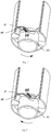
- the condition of the air passage when the storage coiling block rotates is further illustrated in conjunction with Fig. 5 .
- the air disturbance vanes 302 on the storage coiling block 201 drives air to flow, the air passes through a heat-dissipating passage 204 formed between the surface of the power motor 202 and the inner surface of the storage coiling block 201 and takes away the heat at the surface of the motor.
- a flow speed of the air at the driving air port 203 of the storage coiling block 201 is V k
- a flow speed of the air in the heat-dissipating passage 204 on the surface of the power motor 202 is V r .
- FIG. 5 which is a schematic view showing cross sectional areas of the interior of the storage coiling block 201
- an internal cross sectional area of the storage coiling block 201 is S 1
- a cross sectional area of the motor supporting frame is S 2
- a cross sectional area of the power motor is S 3 .
- a width d 2 of the cross section of the power motor is greater than a width d 1 of the motor supporting frame 301, thus S 3 >S 2 .
- the relationship between the area S k of the driving air port 203 and the area S r of the heat-dissipating passage 204 satisfies an expression of S k >S r .
- the flow speed of the airflow formed at the driving air port 203 is increased when passing through the heat-dissipating passage 204 due to the decrease of the passage section, thereby expediting the heat dissipation on the surface of the motor.
- the directions of air exchange when the storage coiling block 201 rotates positively or reversely is further illustrated.
- the air is drawn from the heat-dissipating passage when the power motor 202 rotates in a positive direction, and an inclining direction of the air disturbance vanes 302 is the positive direction.
- an arrangement direction of the vanes may be positive direction or reverse direction according to different inclining directions of the air disturbance vanes 302, both of which may realize the object of the present application.
- a heat dissipation process of the power motor when the sheet-like medium temporary storage device is operating is further illustrated in conjunction with Figures 1 to 8 .
- a sheet-like medium 100 is sent into the sheet-like medium temporary storage device
- a sheet inlet formed between the two guiding shafts 103 of the thin coiling tapes and the two thin coiling tapes 102 is configured to receive the sheet-like medium 100
- the power motor 202 drives the storage coiling block 201 and the big driving wheel 105 to rotate in the positive direction
- the big driving wheel 105 then drives the two small driving wheels 104 to rotate in the positive direction via the drive belt 106
- the two small driving wheels 104 respectively drive two recycling coiling blocks 101 to rotate in the positive direction through two small coiling block rotation shafts 108
- the two recycling coiling blocks 101 respectively release the two thin coiling tapes 102 pre-stored on the two recycling coiling blocks 101 step by step, to wind the sheet-like medium clamped between the two thin coiling tapes 102 around the storage coiling block
- the air disturbance vanes 302 at one end of the storage coiling block 201 rotates around the first power output shaft of the power motor when the storage coiling block 201 rotates. Due to the inclined arrangement of the air disturbance vanes, the inclined surfaces of the air disturbance vanes strike air particles when the air disturbance vanes rotate, which accelerates the movement of the air particles and changes the movement direction of the air particles, and an airflow flowing from the heat-dissipating passage 204 toward the driving air port 203 is formed. Due to the airflow, heat in the heat-dissipating passage 204 generated by the operation of the power motor 202 is taken away by the air in contact with the heat-dissipating passage 204, thereby realizing the object of fast cooling of the power motor.
- the storage coiling block 201 and the big driving wheel 105 are driven to rotate in the reverse direction, the two thin coiling tapes 102 clamping the sheet-like medium 100 are released from the storage coiling block 201, and the two recycling coiling blocks 101 recycle the thin coiling tapes 102 step by step, to release the clamped sheet-like medium piece by piece, thereby accomplishing a discharging function of the sheet-like mediums temporarily stored on the storage coiling block 201.
- the air disturbance vanes 302 at one end of the storage coiling block 201 rotates around the first power output shaft of the power motor when the storage coiling block 201 rotates in the reverse direction.
- the inclined surfaces of the air disturbance vanes strike air particles when the air disturbance vanes rotate, which accelerates the movement of the air particles and changes the movement direction of the air particles, and an airflow flowing from the driving air port 203 toward the heat-dissipating passage 204 is formed. Due to the airflow, heat in the heat-dissipating passage 204 generated by the operation of the power motor 202 is taken away by the air in contact with the heat-dissipating passage 204, thereby realizing the object of fast cooling of the power motor.
- the air disturbance vanes 302 that is the vanes of the coiling block
- the air disturbance vanes 302 are arranged obliquely, and a ventilation space is provided between each two adjacent air disturbance vanes 302, thus even if the power motor stops rotating, that is the storage coiling block 201 stops rotating, heat generated inside the storage coiling block 201 during the operation of the power motor 202 may also be dissipated from these ventilation spaces in a manner of heat convection, which accelerates the natural cooling of the power motor.
Landscapes
- Engineering & Computer Science (AREA)
- Mechanical Engineering (AREA)
- Physics & Mathematics (AREA)
- General Physics & Mathematics (AREA)
- Discharge By Other Means (AREA)
- Pile Receivers (AREA)
- Winding Of Webs (AREA)
- Conveyance By Endless Belt Conveyors (AREA)
- Folding Of Thin Sheet-Like Materials, Special Discharging Devices, And Others (AREA)
- Laminated Bodies (AREA)
Claims (4)
- Zwischenspeichervorrichtung für ein bahnartiges Medium, umfassend:einen Speicherwickelblock (201), der zum Aufrollen und Lagern eines bahnartigen Mediums ausgebildet ist und als kreisförmige Rolle mit einem Hohlraum in der Mitte ausgebildet ist;ein dünnes Wickelband (102), dessen eines Ende fest mit einer Außenfläche des Speicherwickelblocks (201) verbunden ist und dazu ausgebildet ist, das bahnartige Medium aufzuwickeln und das bahnartige Medium um den Speicherwickelblock (201) zu wickeln, um das bahnartige Medium zwischenzuspeichern;einen Recycling-Wickelblock (101), der zum Abstützen des dünnen Wickelbandes (102) und zum Aufrollen und Recyceln des dünnen Wickelbandes (102) ausgebildet ist, wobei ein anderes Ende des dünnen Wickelbandes (102) an einer Außenfläche des Recycling-Wickelblocks (101) befestigt ist;einen Motor (202), der in dem Hohlraum des Speicherwickelblocks (201) angeordnet und zum Antrieb des Speicherwickelblocks (201) zum Drehen und Steuern des Recycling-Wickelblocks (101) ausgebildet ist, um sich durch einen Riemen zu drehen;wobei ein Ende des Hohlraums in der Mitte des Speicherwickelblocks (201) offen ist, um ein montierendes Einsetzen des Motors (202) in den Speicherwickelblock (201) zu ermöglichen, und dadurch gekennzeichnet, dasswenigstens zwei Luftstörschaufeln (302) gleichmäßig an einem anderen Ende des Hohlraums angeordnet sind, wobei sich die Luftstörschaufeln (302) von einer Außenwand zu einer Achse des Speicherwickelblocks (201) erstrecken und einen Stützrahmen des Motors (202) um die Achse des Speicherwickelblocks (201) bilden, und ein Freiraum zwischen den Luftstörflügeln (302) ausgebildet ist, um einen Luftaustausch zwischen dem Inneren und dem Äußeren des Speicherwickelblocks (201) für den Fall sicherzustellen, dass sich der Speicherwickelblock (201) dreht.
- Zwischenspeichervorrichtung für ein bahnartiges Medium nach Anspruch 1, wobei die Anzahl der Luftstörflügel (302) vier beträgt und die vier Luftstörflügel (302) gleichmäßig auf einer Endfläche des Lageraufwickelblocks (201) verteilt sind.
- Zwischenspeichervorrichtung für ein bahnartiges Medium nach Anspruch 1 oder Anspruch 2, wobei die Luftstörflügel (302) einen unregelmäßigen Z-förmigen Verlauf entlang einer Umfangsrichtung bilden.
- Zwischenspeichervorrichtung für ein bahnartiges Medium nach Anspruch 1, wobei zwei der dünnen Wickelbänder (102) vorgesehen und dementsprechend zwei der Recycling-Wickelblöcke (101) vorgesehen sind, wobei die beiden dünnen Wickelbänder (102) jeweils um die beiden Recycling-Wickelblöcke (101) gewickelt sind, deren andere Enden auf der äußeren Oberfläche des Lagerwickelblocks (201) übereinander angeordnet und befestigt sind, und Teile der zwei dünnen Wickelbänder (102) zwischen den Recycling-Wickelblöcken (101) und dem Lagerwickelblock (201) einen Klemmzustand bilden.
Applications Claiming Priority (2)
| Application Number | Priority Date | Filing Date | Title |
|---|---|---|---|
| CN201310072988.8A CN103144993B (zh) | 2013-03-07 | 2013-03-07 | 一种薄片介质暂存装置 |
| PCT/CN2013/078735 WO2014134892A1 (zh) | 2013-03-07 | 2013-07-03 | 一种薄片介质暂存装置 |
Publications (3)
| Publication Number | Publication Date |
|---|---|
| EP2966018A1 EP2966018A1 (de) | 2016-01-13 |
| EP2966018A4 EP2966018A4 (de) | 2016-07-27 |
| EP2966018B1 true EP2966018B1 (de) | 2018-04-18 |
Family
ID=48543384
Family Applications (1)
| Application Number | Title | Priority Date | Filing Date |
|---|---|---|---|
| EP13877045.8A Not-in-force EP2966018B1 (de) | 2013-03-07 | 2013-07-03 | Vorübergehende lagerungsvorrichtung für bahnförmiges medium |
Country Status (8)
| Country | Link |
|---|---|
| US (1) | US9670023B2 (de) |
| EP (1) | EP2966018B1 (de) |
| CN (1) | CN103144993B (de) |
| AU (1) | AU2013380740B2 (de) |
| CL (1) | CL2015002219A1 (de) |
| TR (1) | TR201807802T4 (de) |
| WO (1) | WO2014134892A1 (de) |
| ZA (1) | ZA201505900B (de) |
Families Citing this family (3)
| Publication number | Priority date | Publication date | Assignee | Title |
|---|---|---|---|---|
| CN103144993B (zh) * | 2013-03-07 | 2015-06-17 | 广州广电运通金融电子股份有限公司 | 一种薄片介质暂存装置 |
| CN108847751B (zh) * | 2018-06-28 | 2024-06-28 | 苏州索尔达动力科技有限公司 | 一种新能源汽车用驱动电机的风冷系统 |
| US11807481B2 (en) * | 2020-08-27 | 2023-11-07 | Ncr Corporation | Single tape escrow module |
Family Cites Families (10)
| Publication number | Priority date | Publication date | Assignee | Title |
|---|---|---|---|---|
| OA04528A (fr) * | 1972-04-27 | 1980-03-30 | Granger Maurice | Dispositif de distribution et coupe simultannées de bandes de matériaux enroulés. |
| DE4223839C1 (de) * | 1992-07-20 | 1993-12-23 | Heidelberger Druckmasch Ag | Bogenführungszylinder einer Druckmaschine |
| CA2299827C (en) * | 2000-03-02 | 2009-12-15 | Cashcode Company Inc. | Combination banknote validator and banknote dispenser |
| JP4200048B2 (ja) * | 2003-06-03 | 2008-12-24 | 日立オムロンターミナルソリューションズ株式会社 | 紙葉類収納放出装置 |
| DE102005048041A1 (de) * | 2005-10-07 | 2007-04-12 | Saurer Gmbh & Co. Kg | Fadenabzugseinrichtung für eine Kreuzspulen herstellende Textilmaschine |
| RU2461068C2 (ru) | 2007-06-27 | 2012-09-10 | Меи, Инк. | Устройство обработки банкнот |
| JP4811432B2 (ja) * | 2008-06-24 | 2011-11-09 | 沖電気工業株式会社 | 媒体収納繰出装置 |
| ES2356003B1 (es) | 2009-01-22 | 2012-03-20 | Azkoyen Medios De Pago, S.A. | Acumulador temporal de billetes. |
| CN201952069U (zh) | 2010-10-19 | 2011-08-31 | 科诚股份有限公司 | 通用型卷供料器 |
| CN103144993B (zh) | 2013-03-07 | 2015-06-17 | 广州广电运通金融电子股份有限公司 | 一种薄片介质暂存装置 |
-
2013
- 2013-03-07 CN CN201310072988.8A patent/CN103144993B/zh active Active
- 2013-07-03 WO PCT/CN2013/078735 patent/WO2014134892A1/zh not_active Ceased
- 2013-07-03 AU AU2013380740A patent/AU2013380740B2/en not_active Ceased
- 2013-07-03 US US14/767,328 patent/US9670023B2/en not_active Expired - Fee Related
- 2013-07-03 EP EP13877045.8A patent/EP2966018B1/de not_active Not-in-force
- 2013-07-03 TR TR2018/07802T patent/TR201807802T4/tr unknown
-
2015
- 2015-08-07 CL CL2015002219A patent/CL2015002219A1/es unknown
- 2015-08-17 ZA ZA2015/05900A patent/ZA201505900B/en unknown
Non-Patent Citations (1)
| Title |
|---|
| None * |
Also Published As
| Publication number | Publication date |
|---|---|
| AU2013380740A1 (en) | 2015-09-03 |
| WO2014134892A1 (zh) | 2014-09-12 |
| US9670023B2 (en) | 2017-06-06 |
| TR201807802T4 (tr) | 2018-06-21 |
| EP2966018A4 (de) | 2016-07-27 |
| ZA201505900B (en) | 2016-07-27 |
| EP2966018A1 (de) | 2016-01-13 |
| CN103144993B (zh) | 2015-06-17 |
| CN103144993A (zh) | 2013-06-12 |
| CL2015002219A1 (es) | 2015-11-20 |
| AU2013380740B2 (en) | 2015-12-17 |
| US20160009517A1 (en) | 2016-01-14 |
Similar Documents
| Publication | Publication Date | Title |
|---|---|---|
| RU2670879C9 (ru) | Устройство временного хранения бумажных денег | |
| JP6194926B2 (ja) | 回転電機のロータ | |
| US10214376B2 (en) | Sheet medium flattening device and financial self-service device | |
| US20180354737A1 (en) | Double-coiling-belt paper money temporary storage device | |
| US9670023B2 (en) | Temporary storage device for sheet medium | |
| US10447115B2 (en) | Rotary electric machine and driving system | |
| WO2018141107A1 (zh) | 一种存款终端及存取款系统 | |
| CN103166340A (zh) | 旋转电机及具备该旋转电机的铁道车辆以及电动车辆 | |
| EP3713048B1 (de) | Elektrische drehmaschine | |
| JP7758125B2 (ja) | カセット | |
| JP2023029392A (ja) | カセット | |
| US20160222974A1 (en) | Stator Component of Vacuum Pump | |
| US20150115752A1 (en) | Open-type induction motor | |
| WO2019159240A1 (ja) | 回転電機 | |
| JP5877518B2 (ja) | 紙幣搬送機構および紙幣入出金装置 | |
| US20150349608A1 (en) | Axial Gap Motor | |
| JP2015102644A (ja) | 送風装置、送風装置用ホルダ、排紙装置及び画像形成装置 | |
| JP7272064B2 (ja) | カセット | |
| CN1991919B (zh) | 暂存器机构 | |
| CN111313580A (zh) | 一种永磁直驱滚筒 | |
| JP2010161291A (ja) | 電源ユニットを具えた装置の冷却装置 | |
| WO2019174562A1 (zh) | 叶轮组件、纸币集积分离装置及现金循环处理设备 | |
| CN211545304U (zh) | 薄片类介质输送机构和现金循环处理设备 | |
| CN208796344U (zh) | 暂存装置及介质处理机 | |
| JP5507516B2 (ja) | 媒体回収装置および媒体回収方法 |
Legal Events
| Date | Code | Title | Description |
|---|---|---|---|
| PUAI | Public reference made under article 153(3) epc to a published international application that has entered the european phase |
Free format text: ORIGINAL CODE: 0009012 |
|
| 17P | Request for examination filed |
Effective date: 20150728 |
|
| AK | Designated contracting states |
Kind code of ref document: A1 Designated state(s): AL AT BE BG CH CY CZ DE DK EE ES FI FR GB GR HR HU IE IS IT LI LT LU LV MC MK MT NL NO PL PT RO RS SE SI SK SM TR |
|
| AX | Request for extension of the european patent |
Extension state: BA ME |
|
| DAX | Request for extension of the european patent (deleted) | ||
| A4 | Supplementary search report drawn up and despatched |
Effective date: 20160628 |
|
| RIC1 | Information provided on ipc code assigned before grant |
Ipc: B65H 33/14 20060101AFI20160622BHEP |
|
| GRAP | Despatch of communication of intention to grant a patent |
Free format text: ORIGINAL CODE: EPIDOSNIGR1 |
|
| STAA | Information on the status of an ep patent application or granted ep patent |
Free format text: STATUS: GRANT OF PATENT IS INTENDED |
|
| RIC1 | Information provided on ipc code assigned before grant |
Ipc: G07D 11/00 20060101ALI20171013BHEP Ipc: B65H 29/00 20060101ALI20171013BHEP Ipc: B65H 33/14 20060101AFI20171013BHEP |
|
| INTG | Intention to grant announced |
Effective date: 20171108 |
|
| GRAS | Grant fee paid |
Free format text: ORIGINAL CODE: EPIDOSNIGR3 |
|
| GRAA | (expected) grant |
Free format text: ORIGINAL CODE: 0009210 |
|
| STAA | Information on the status of an ep patent application or granted ep patent |
Free format text: STATUS: THE PATENT HAS BEEN GRANTED |
|
| AK | Designated contracting states |
Kind code of ref document: B1 Designated state(s): AL AT BE BG CH CY CZ DE DK EE ES FI FR GB GR HR HU IE IS IT LI LT LU LV MC MK MT NL NO PL PT RO RS SE SI SK SM TR |
|
| REG | Reference to a national code |
Ref country code: GB Ref legal event code: FG4D |
|
| REG | Reference to a national code |
Ref country code: CH Ref legal event code: EP |
|
| REG | Reference to a national code |
Ref country code: AT Ref legal event code: REF Ref document number: 990215 Country of ref document: AT Kind code of ref document: T Effective date: 20180515 |
|
| REG | Reference to a national code |
Ref country code: IE Ref legal event code: FG4D |
|
| REG | Reference to a national code |
Ref country code: DE Ref legal event code: R096 Ref document number: 602013036286 Country of ref document: DE |
|
| REG | Reference to a national code |
Ref country code: FR Ref legal event code: PLFP Year of fee payment: 6 |
|
| REG | Reference to a national code |
Ref country code: NL Ref legal event code: MP Effective date: 20180418 |
|
| REG | Reference to a national code |
Ref country code: LT Ref legal event code: MG4D |
|
| PG25 | Lapsed in a contracting state [announced via postgrant information from national office to epo] |
Ref country code: NL Free format text: LAPSE BECAUSE OF FAILURE TO SUBMIT A TRANSLATION OF THE DESCRIPTION OR TO PAY THE FEE WITHIN THE PRESCRIBED TIME-LIMIT Effective date: 20180418 |
|
| PG25 | Lapsed in a contracting state [announced via postgrant information from national office to epo] |
Ref country code: LT Free format text: LAPSE BECAUSE OF FAILURE TO SUBMIT A TRANSLATION OF THE DESCRIPTION OR TO PAY THE FEE WITHIN THE PRESCRIBED TIME-LIMIT Effective date: 20180418 Ref country code: SE Free format text: LAPSE BECAUSE OF FAILURE TO SUBMIT A TRANSLATION OF THE DESCRIPTION OR TO PAY THE FEE WITHIN THE PRESCRIBED TIME-LIMIT Effective date: 20180418 Ref country code: FI Free format text: LAPSE BECAUSE OF FAILURE TO SUBMIT A TRANSLATION OF THE DESCRIPTION OR TO PAY THE FEE WITHIN THE PRESCRIBED TIME-LIMIT Effective date: 20180418 Ref country code: BG Free format text: LAPSE BECAUSE OF FAILURE TO SUBMIT A TRANSLATION OF THE DESCRIPTION OR TO PAY THE FEE WITHIN THE PRESCRIBED TIME-LIMIT Effective date: 20180718 Ref country code: AL Free format text: LAPSE BECAUSE OF FAILURE TO SUBMIT A TRANSLATION OF THE DESCRIPTION OR TO PAY THE FEE WITHIN THE PRESCRIBED TIME-LIMIT Effective date: 20180418 Ref country code: ES Free format text: LAPSE BECAUSE OF FAILURE TO SUBMIT A TRANSLATION OF THE DESCRIPTION OR TO PAY THE FEE WITHIN THE PRESCRIBED TIME-LIMIT Effective date: 20180418 Ref country code: NO Free format text: LAPSE BECAUSE OF FAILURE TO SUBMIT A TRANSLATION OF THE DESCRIPTION OR TO PAY THE FEE WITHIN THE PRESCRIBED TIME-LIMIT Effective date: 20180718 Ref country code: PL Free format text: LAPSE BECAUSE OF FAILURE TO SUBMIT A TRANSLATION OF THE DESCRIPTION OR TO PAY THE FEE WITHIN THE PRESCRIBED TIME-LIMIT Effective date: 20180418 |
|
| PG25 | Lapsed in a contracting state [announced via postgrant information from national office to epo] |
Ref country code: LV Free format text: LAPSE BECAUSE OF FAILURE TO SUBMIT A TRANSLATION OF THE DESCRIPTION OR TO PAY THE FEE WITHIN THE PRESCRIBED TIME-LIMIT Effective date: 20180418 Ref country code: GR Free format text: LAPSE BECAUSE OF FAILURE TO SUBMIT A TRANSLATION OF THE DESCRIPTION OR TO PAY THE FEE WITHIN THE PRESCRIBED TIME-LIMIT Effective date: 20180719 Ref country code: HR Free format text: LAPSE BECAUSE OF FAILURE TO SUBMIT A TRANSLATION OF THE DESCRIPTION OR TO PAY THE FEE WITHIN THE PRESCRIBED TIME-LIMIT Effective date: 20180418 Ref country code: RS Free format text: LAPSE BECAUSE OF FAILURE TO SUBMIT A TRANSLATION OF THE DESCRIPTION OR TO PAY THE FEE WITHIN THE PRESCRIBED TIME-LIMIT Effective date: 20180418 |
|
| PG25 | Lapsed in a contracting state [announced via postgrant information from national office to epo] |
Ref country code: PT Free format text: LAPSE BECAUSE OF FAILURE TO SUBMIT A TRANSLATION OF THE DESCRIPTION OR TO PAY THE FEE WITHIN THE PRESCRIBED TIME-LIMIT Effective date: 20180820 |
|
| REG | Reference to a national code |
Ref country code: DE Ref legal event code: R097 Ref document number: 602013036286 Country of ref document: DE |
|
| PG25 | Lapsed in a contracting state [announced via postgrant information from national office to epo] |
Ref country code: CZ Free format text: LAPSE BECAUSE OF FAILURE TO SUBMIT A TRANSLATION OF THE DESCRIPTION OR TO PAY THE FEE WITHIN THE PRESCRIBED TIME-LIMIT Effective date: 20180418 Ref country code: RO Free format text: LAPSE BECAUSE OF FAILURE TO SUBMIT A TRANSLATION OF THE DESCRIPTION OR TO PAY THE FEE WITHIN THE PRESCRIBED TIME-LIMIT Effective date: 20180418 Ref country code: SK Free format text: LAPSE BECAUSE OF FAILURE TO SUBMIT A TRANSLATION OF THE DESCRIPTION OR TO PAY THE FEE WITHIN THE PRESCRIBED TIME-LIMIT Effective date: 20180418 Ref country code: EE Free format text: LAPSE BECAUSE OF FAILURE TO SUBMIT A TRANSLATION OF THE DESCRIPTION OR TO PAY THE FEE WITHIN THE PRESCRIBED TIME-LIMIT Effective date: 20180418 Ref country code: DK Free format text: LAPSE BECAUSE OF FAILURE TO SUBMIT A TRANSLATION OF THE DESCRIPTION OR TO PAY THE FEE WITHIN THE PRESCRIBED TIME-LIMIT Effective date: 20180418 |
|
| PLBE | No opposition filed within time limit |
Free format text: ORIGINAL CODE: 0009261 |
|
| STAA | Information on the status of an ep patent application or granted ep patent |
Free format text: STATUS: NO OPPOSITION FILED WITHIN TIME LIMIT |
|
| PG25 | Lapsed in a contracting state [announced via postgrant information from national office to epo] |
Ref country code: SM Free format text: LAPSE BECAUSE OF FAILURE TO SUBMIT A TRANSLATION OF THE DESCRIPTION OR TO PAY THE FEE WITHIN THE PRESCRIBED TIME-LIMIT Effective date: 20180418 |
|
| REG | Reference to a national code |
Ref country code: CH Ref legal event code: PL |
|
| 26N | No opposition filed |
Effective date: 20190121 |
|
| PG25 | Lapsed in a contracting state [announced via postgrant information from national office to epo] |
Ref country code: MC Free format text: LAPSE BECAUSE OF FAILURE TO SUBMIT A TRANSLATION OF THE DESCRIPTION OR TO PAY THE FEE WITHIN THE PRESCRIBED TIME-LIMIT Effective date: 20180418 Ref country code: LU Free format text: LAPSE BECAUSE OF NON-PAYMENT OF DUE FEES Effective date: 20180703 |
|
| REG | Reference to a national code |
Ref country code: BE Ref legal event code: MM Effective date: 20180731 |
|
| REG | Reference to a national code |
Ref country code: IE Ref legal event code: MM4A |
|
| PG25 | Lapsed in a contracting state [announced via postgrant information from national office to epo] |
Ref country code: LI Free format text: LAPSE BECAUSE OF NON-PAYMENT OF DUE FEES Effective date: 20180731 Ref country code: IE Free format text: LAPSE BECAUSE OF NON-PAYMENT OF DUE FEES Effective date: 20180703 Ref country code: CH Free format text: LAPSE BECAUSE OF NON-PAYMENT OF DUE FEES Effective date: 20180731 |
|
| PG25 | Lapsed in a contracting state [announced via postgrant information from national office to epo] |
Ref country code: BE Free format text: LAPSE BECAUSE OF NON-PAYMENT OF DUE FEES Effective date: 20180731 Ref country code: SI Free format text: LAPSE BECAUSE OF FAILURE TO SUBMIT A TRANSLATION OF THE DESCRIPTION OR TO PAY THE FEE WITHIN THE PRESCRIBED TIME-LIMIT Effective date: 20180418 |
|
| PGFP | Annual fee paid to national office [announced via postgrant information from national office to epo] |
Ref country code: FR Payment date: 20190731 Year of fee payment: 7 Ref country code: DE Payment date: 20190807 Year of fee payment: 7 Ref country code: IT Payment date: 20190710 Year of fee payment: 7 |
|
| PGFP | Annual fee paid to national office [announced via postgrant information from national office to epo] |
Ref country code: AT Payment date: 20190725 Year of fee payment: 7 Ref country code: GB Payment date: 20190821 Year of fee payment: 7 |
|
| PG25 | Lapsed in a contracting state [announced via postgrant information from national office to epo] |
Ref country code: MT Free format text: LAPSE BECAUSE OF NON-PAYMENT OF DUE FEES Effective date: 20180703 |
|
| PG25 | Lapsed in a contracting state [announced via postgrant information from national office to epo] |
Ref country code: CY Free format text: LAPSE BECAUSE OF FAILURE TO SUBMIT A TRANSLATION OF THE DESCRIPTION OR TO PAY THE FEE WITHIN THE PRESCRIBED TIME-LIMIT Effective date: 20180418 Ref country code: MK Free format text: LAPSE BECAUSE OF NON-PAYMENT OF DUE FEES Effective date: 20180418 Ref country code: HU Free format text: LAPSE BECAUSE OF FAILURE TO SUBMIT A TRANSLATION OF THE DESCRIPTION OR TO PAY THE FEE WITHIN THE PRESCRIBED TIME-LIMIT; INVALID AB INITIO Effective date: 20130703 |
|
| PG25 | Lapsed in a contracting state [announced via postgrant information from national office to epo] |
Ref country code: IS Free format text: LAPSE BECAUSE OF FAILURE TO SUBMIT A TRANSLATION OF THE DESCRIPTION OR TO PAY THE FEE WITHIN THE PRESCRIBED TIME-LIMIT Effective date: 20180818 |
|
| REG | Reference to a national code |
Ref country code: DE Ref legal event code: R119 Ref document number: 602013036286 Country of ref document: DE |
|
| REG | Reference to a national code |
Ref country code: AT Ref legal event code: MM01 Ref document number: 990215 Country of ref document: AT Kind code of ref document: T Effective date: 20200703 Ref country code: AT Ref legal event code: UEP Ref document number: 990215 Country of ref document: AT Kind code of ref document: T Effective date: 20180418 |
|
| GBPC | Gb: european patent ceased through non-payment of renewal fee |
Effective date: 20200703 |
|
| PG25 | Lapsed in a contracting state [announced via postgrant information from national office to epo] |
Ref country code: FR Free format text: LAPSE BECAUSE OF NON-PAYMENT OF DUE FEES Effective date: 20200731 Ref country code: GB Free format text: LAPSE BECAUSE OF NON-PAYMENT OF DUE FEES Effective date: 20200703 |
|
| PG25 | Lapsed in a contracting state [announced via postgrant information from national office to epo] |
Ref country code: AT Free format text: LAPSE BECAUSE OF NON-PAYMENT OF DUE FEES Effective date: 20200703 Ref country code: DE Free format text: LAPSE BECAUSE OF NON-PAYMENT OF DUE FEES Effective date: 20210202 |
|
| PG25 | Lapsed in a contracting state [announced via postgrant information from national office to epo] |
Ref country code: IT Free format text: LAPSE BECAUSE OF NON-PAYMENT OF DUE FEES Effective date: 20200703 |
|
| PG25 | Lapsed in a contracting state [announced via postgrant information from national office to epo] |
Ref country code: TR Free format text: LAPSE BECAUSE OF NON-PAYMENT OF DUE FEES Effective date: 20200703 |