EP2965266B1 - Bouchons et couvercles rfid - Google Patents
Bouchons et couvercles rfid Download PDFInfo
- Publication number
- EP2965266B1 EP2965266B1 EP14710359.2A EP14710359A EP2965266B1 EP 2965266 B1 EP2965266 B1 EP 2965266B1 EP 14710359 A EP14710359 A EP 14710359A EP 2965266 B1 EP2965266 B1 EP 2965266B1
- Authority
- EP
- European Patent Office
- Prior art keywords
- rfid
- cap
- vial
- array
- box
- Prior art date
- Legal status (The legal status is an assumption and is not a legal conclusion. Google has not performed a legal analysis and makes no representation as to the accuracy of the status listed.)
- Active
Links
- 239000000523 sample Substances 0.000 description 28
- 239000012472 biological sample Substances 0.000 description 9
- 238000000034 method Methods 0.000 description 8
- 230000006378 damage Effects 0.000 description 7
- 239000003822 epoxy resin Substances 0.000 description 6
- 229920000647 polyepoxide Polymers 0.000 description 6
- 238000009420 retrofitting Methods 0.000 description 6
- 239000010410 layer Substances 0.000 description 5
- IJGRMHOSHXDMSA-UHFFFAOYSA-N Atomic nitrogen Chemical compound N#N IJGRMHOSHXDMSA-UHFFFAOYSA-N 0.000 description 4
- 239000004593 Epoxy Substances 0.000 description 4
- 239000000463 material Substances 0.000 description 4
- 229910000859 α-Fe Inorganic materials 0.000 description 4
- 239000004743 Polypropylene Substances 0.000 description 2
- 238000012550 audit Methods 0.000 description 2
- 239000007789 gas Substances 0.000 description 2
- 230000002427 irreversible effect Effects 0.000 description 2
- 239000007788 liquid Substances 0.000 description 2
- 238000012544 monitoring process Methods 0.000 description 2
- 229910052757 nitrogen Inorganic materials 0.000 description 2
- -1 polypropylene Polymers 0.000 description 2
- 229920001155 polypropylene Polymers 0.000 description 2
- 239000007787 solid Substances 0.000 description 2
- 101100480513 Caenorhabditis elegans tag-52 gene Proteins 0.000 description 1
- RYGMFSIKBFXOCR-UHFFFAOYSA-N Copper Chemical compound [Cu] RYGMFSIKBFXOCR-UHFFFAOYSA-N 0.000 description 1
- IAYPIBMASNFSPL-UHFFFAOYSA-N Ethylene oxide Chemical compound C1CO1 IAYPIBMASNFSPL-UHFFFAOYSA-N 0.000 description 1
- XUIMIQQOPSSXEZ-UHFFFAOYSA-N Silicon Chemical compound [Si] XUIMIQQOPSSXEZ-UHFFFAOYSA-N 0.000 description 1
- 239000012790 adhesive layer Substances 0.000 description 1
- 238000003491 array Methods 0.000 description 1
- 230000009286 beneficial effect Effects 0.000 description 1
- 229910052802 copper Inorganic materials 0.000 description 1
- 239000010949 copper Substances 0.000 description 1
- 238000010586 diagram Methods 0.000 description 1
- 230000008014 freezing Effects 0.000 description 1
- 238000007710 freezing Methods 0.000 description 1
- 239000003292 glue Substances 0.000 description 1
- 239000011810 insulating material Substances 0.000 description 1
- 238000012986 modification Methods 0.000 description 1
- 230000004048 modification Effects 0.000 description 1
- 230000003287 optical effect Effects 0.000 description 1
- 239000010902 straw Substances 0.000 description 1
- 239000000126 substance Substances 0.000 description 1
- 239000012780 transparent material Substances 0.000 description 1
Images


Classifications
-
- G—PHYSICS
- G06—COMPUTING; CALCULATING OR COUNTING
- G06K—GRAPHICAL DATA READING; PRESENTATION OF DATA; RECORD CARRIERS; HANDLING RECORD CARRIERS
- G06K19/00—Record carriers for use with machines and with at least a part designed to carry digital markings
- G06K19/06—Record carriers for use with machines and with at least a part designed to carry digital markings characterised by the kind of the digital marking, e.g. shape, nature, code
- G06K19/067—Record carriers with conductive marks, printed circuits or semiconductor circuit elements, e.g. credit or identity cards also with resonating or responding marks without active components
- G06K19/07—Record carriers with conductive marks, printed circuits or semiconductor circuit elements, e.g. credit or identity cards also with resonating or responding marks without active components with integrated circuit chips
- G06K19/077—Constructional details, e.g. mounting of circuits in the carrier
- G06K19/07749—Constructional details, e.g. mounting of circuits in the carrier the record carrier being capable of non-contact communication, e.g. constructional details of the antenna of a non-contact smart card
- G06K19/07758—Constructional details, e.g. mounting of circuits in the carrier the record carrier being capable of non-contact communication, e.g. constructional details of the antenna of a non-contact smart card arrangements for adhering the record carrier to further objects or living beings, functioning as an identification tag
-
- A—HUMAN NECESSITIES
- A61—MEDICAL OR VETERINARY SCIENCE; HYGIENE
- A61J—CONTAINERS SPECIALLY ADAPTED FOR MEDICAL OR PHARMACEUTICAL PURPOSES; DEVICES OR METHODS SPECIALLY ADAPTED FOR BRINGING PHARMACEUTICAL PRODUCTS INTO PARTICULAR PHYSICAL OR ADMINISTERING FORMS; DEVICES FOR ADMINISTERING FOOD OR MEDICINES ORALLY; BABY COMFORTERS; DEVICES FOR RECEIVING SPITTLE
- A61J1/00—Containers specially adapted for medical or pharmaceutical purposes
- A61J1/14—Details; Accessories therefor
- A61J1/1412—Containers with closing means, e.g. caps
- A61J1/1418—Threaded type
-
- A—HUMAN NECESSITIES
- A61—MEDICAL OR VETERINARY SCIENCE; HYGIENE
- A61J—CONTAINERS SPECIALLY ADAPTED FOR MEDICAL OR PHARMACEUTICAL PURPOSES; DEVICES OR METHODS SPECIALLY ADAPTED FOR BRINGING PHARMACEUTICAL PRODUCTS INTO PARTICULAR PHYSICAL OR ADMINISTERING FORMS; DEVICES FOR ADMINISTERING FOOD OR MEDICINES ORALLY; BABY COMFORTERS; DEVICES FOR RECEIVING SPITTLE
- A61J1/00—Containers specially adapted for medical or pharmaceutical purposes
- A61J1/14—Details; Accessories therefor
- A61J1/16—Holders for containers
- A61J1/165—Cooled holders, e.g. for medications, insulin, blood, plasma
-
- B—PERFORMING OPERATIONS; TRANSPORTING
- B65—CONVEYING; PACKING; STORING; HANDLING THIN OR FILAMENTARY MATERIAL
- B65D—CONTAINERS FOR STORAGE OR TRANSPORT OF ARTICLES OR MATERIALS, e.g. BAGS, BARRELS, BOTTLES, BOXES, CANS, CARTONS, CRATES, DRUMS, JARS, TANKS, HOPPERS, FORWARDING CONTAINERS; ACCESSORIES, CLOSURES, OR FITTINGS THEREFOR; PACKAGING ELEMENTS; PACKAGES
- B65D43/00—Lids or covers for rigid or semi-rigid containers
- B65D43/02—Removable lids or covers
- B65D43/06—Removable lids or covers having a peripheral channel embracing the rim of the container
- B65D43/065—Removable lids or covers having a peripheral channel embracing the rim of the container the peripheral channel having an inverted U-shape
-
- B—PERFORMING OPERATIONS; TRANSPORTING
- B65—CONVEYING; PACKING; STORING; HANDLING THIN OR FILAMENTARY MATERIAL
- B65D—CONTAINERS FOR STORAGE OR TRANSPORT OF ARTICLES OR MATERIALS, e.g. BAGS, BARRELS, BOTTLES, BOXES, CANS, CARTONS, CRATES, DRUMS, JARS, TANKS, HOPPERS, FORWARDING CONTAINERS; ACCESSORIES, CLOSURES, OR FITTINGS THEREFOR; PACKAGING ELEMENTS; PACKAGES
- B65D81/00—Containers, packaging elements, or packages, for contents presenting particular transport or storage problems, or adapted to be used for non-packaging purposes after removal of contents
- B65D81/18—Containers, packaging elements, or packages, for contents presenting particular transport or storage problems, or adapted to be used for non-packaging purposes after removal of contents providing specific environment for contents, e.g. temperature above or below ambient
-
- B—PERFORMING OPERATIONS; TRANSPORTING
- B65—CONVEYING; PACKING; STORING; HANDLING THIN OR FILAMENTARY MATERIAL
- B65D—CONTAINERS FOR STORAGE OR TRANSPORT OF ARTICLES OR MATERIALS, e.g. BAGS, BARRELS, BOTTLES, BOXES, CANS, CARTONS, CRATES, DRUMS, JARS, TANKS, HOPPERS, FORWARDING CONTAINERS; ACCESSORIES, CLOSURES, OR FITTINGS THEREFOR; PACKAGING ELEMENTS; PACKAGES
- B65D81/00—Containers, packaging elements, or packages, for contents presenting particular transport or storage problems, or adapted to be used for non-packaging purposes after removal of contents
- B65D81/38—Containers, packaging elements, or packages, for contents presenting particular transport or storage problems, or adapted to be used for non-packaging purposes after removal of contents with thermal insulation
- B65D81/3825—Containers, packaging elements, or packages, for contents presenting particular transport or storage problems, or adapted to be used for non-packaging purposes after removal of contents with thermal insulation rigid container being in the form of a box, tray or like container with one or more containers located inside the external container
- B65D81/3827—Containers, packaging elements, or packages, for contents presenting particular transport or storage problems, or adapted to be used for non-packaging purposes after removal of contents with thermal insulation rigid container being in the form of a box, tray or like container with one or more containers located inside the external container the external tray being formed of foam material
-
- G—PHYSICS
- G06—COMPUTING; CALCULATING OR COUNTING
- G06K—GRAPHICAL DATA READING; PRESENTATION OF DATA; RECORD CARRIERS; HANDLING RECORD CARRIERS
- G06K19/00—Record carriers for use with machines and with at least a part designed to carry digital markings
- G06K19/06—Record carriers for use with machines and with at least a part designed to carry digital markings characterised by the kind of the digital marking, e.g. shape, nature, code
- G06K19/067—Record carriers with conductive marks, printed circuits or semiconductor circuit elements, e.g. credit or identity cards also with resonating or responding marks without active components
- G06K19/07—Record carriers with conductive marks, printed circuits or semiconductor circuit elements, e.g. credit or identity cards also with resonating or responding marks without active components with integrated circuit chips
- G06K19/077—Constructional details, e.g. mounting of circuits in the carrier
- G06K19/07749—Constructional details, e.g. mounting of circuits in the carrier the record carrier being capable of non-contact communication, e.g. constructional details of the antenna of a non-contact smart card
- G06K19/07758—Constructional details, e.g. mounting of circuits in the carrier the record carrier being capable of non-contact communication, e.g. constructional details of the antenna of a non-contact smart card arrangements for adhering the record carrier to further objects or living beings, functioning as an identification tag
- G06K19/0776—Constructional details, e.g. mounting of circuits in the carrier the record carrier being capable of non-contact communication, e.g. constructional details of the antenna of a non-contact smart card arrangements for adhering the record carrier to further objects or living beings, functioning as an identification tag the adhering arrangement being a layer of adhesive, so that the record carrier can function as a sticker
-
- G—PHYSICS
- G06—COMPUTING; CALCULATING OR COUNTING
- G06K—GRAPHICAL DATA READING; PRESENTATION OF DATA; RECORD CARRIERS; HANDLING RECORD CARRIERS
- G06K19/00—Record carriers for use with machines and with at least a part designed to carry digital markings
- G06K19/06—Record carriers for use with machines and with at least a part designed to carry digital markings characterised by the kind of the digital marking, e.g. shape, nature, code
- G06K19/067—Record carriers with conductive marks, printed circuits or semiconductor circuit elements, e.g. credit or identity cards also with resonating or responding marks without active components
- G06K19/07—Record carriers with conductive marks, printed circuits or semiconductor circuit elements, e.g. credit or identity cards also with resonating or responding marks without active components with integrated circuit chips
- G06K19/077—Constructional details, e.g. mounting of circuits in the carrier
- G06K19/07749—Constructional details, e.g. mounting of circuits in the carrier the record carrier being capable of non-contact communication, e.g. constructional details of the antenna of a non-contact smart card
- G06K19/07773—Antenna details
- G06K19/07777—Antenna details the antenna being of the inductive type
- G06K19/07779—Antenna details the antenna being of the inductive type the inductive antenna being a coil
- G06K19/07781—Antenna details the antenna being of the inductive type the inductive antenna being a coil the coil being fabricated in a winding process
Definitions
- the present invention relates to an RFID box lid for a cryogenic vial storage box.
- Biological samples may be preserved by cryogenic freezing.
- the biological samples are usually stored in disposable containers (disposables).
- the type of disposable container used depends on the type of sample. Examples of commonly used disposable containers include vials, straws and bags.
- the disposable container is stored at low temperatures in a Dewar flask typically filled with liquid nitrogen at a cryogenic temperature of -196 °C.
- Vials are generally tubular in shape, with a tubular wall defining a main longitudinal cavity (the sample cavity) for storage of the sample.
- the sample cavity can be sealed by a cap before storage of the sample under cryogenic conditions.
- vials Where biological samples are stored in vials, it is common practice for multiple vials to be stored together in standardized storage boxes. Such storage boxes may for example have slots for 100 vials in a 10 ⁇ 10 array or slots for 169 vials in a 13 ⁇ 13 array. Storage boxes having many other configurations of n ⁇ m arrays exist. For example, a 3 ⁇ 3 array is often used for larger vials.
- vials include a diameter of 10mm and a diameter of 12mm although the diameter of the vial can be larger e.g. 25mm.
- Stored biological samples can be identified by writing on the disposable containers themselves or by writing on labels which are then attached to the containers. These labels may be handwritten or printed and can include bar codes.
- Access to stored samples will occasionally be required, for example when performing an audit. However, when the samples are being accessed, they should not be allowed to warm up to temperatures greater than -130°C. It is therefore desirable to minimise the amount of time that a sample spends outside of the Dewar wherever possible.
- RFID Radio Frequency ID
- RFID components for medical storage operate at an approved frequency of 13.56 MHz. It is important that the frequency used for the RFID tag does not lead to any undesirable interference with other electronic medical equipment. Lower medically approved frequency bands such as 125 KHz do not provide enough signal bandwidth to provide the tag with a useful user defined memory.
- An RFID reader can be used to transmit an encoded radio signal to an RFID tag in order to interrogate it.
- the RFID tag Upon receiving the interrogation signal, the RFID tag transmits its identification information to the reader.
- This identification information may be a unique serial number assigned to a particular patient or to a particular sample.
- Another option is to transfer the sample from its vial to an RFID tagged vial. However, this would require the sample to be warmed up which is extremely undesirable as it will almost certainly lead to damage of the sample.
- cryogenic vials of samples are stored together in standardized boxes, tagging of each sample in the box will take a considerable amount of time. Any amount of time that the Dewar is open to room temperature is undesirable.
- JP2005-321935 describes a detachable integrated circuit tag to be mounted on the opening of a container.
- US2013/0027185 describes an RFID specimen transport puck that can be used in the process of performing overall efficient wanding, racking, transporting and tracking of specimens in a lab.
- WO2007/024540 describes a hierarchical sample coding and storage system.
- an RFID cap for a cryogenic vial which does not form part of the present invention, the RFID cap comprising a cap body; and an RFID tag attached to the cap body, the RFID tag comprising an RFID chip and an antenna connected to the chip.
- the RFID tag includes a support medium which encapsulates the RFID chip and antenna.
- the support medium is an epoxy resin. Even more preferably, the support medium is an epoxy resin having a coefficient of expansion of less than 105ppm/°C (below Tg).
- the epoxy resin has a coefficient of expansion within the range of 95-105ppm/°C (below Tg).
- the epoxy resin preferably has a high dielectric strength and is therefore a good insulating material. This means that the amount of radio frequency energy absorbed by the epoxy material during tag operation is reduced.
- the epoxy resin preferably bonds to a wide variety of substances including silicon chips and copper wires.
- the epoxy resin is preferably resilient to ethylene oxide gas and similar vapours and gases.
- An example of a suitable epoxy material is Tra-bond F123.
- the encapsulating body may take the form of a solid disc.
- the disc may have a diameter equal to that of the antenna or may have a diameter larger than the antenna.
- the cap body includes a top portion and a wall extending from the top portion, the wall including attachment means.
- the RFID tag is located at the top portion of the cap.
- the RFID cap enables a tagged vial to be easily accessed by an RFID reader.
- the top portion of the cap body includes positioning elements to align the RFID tag with the central axis of the cap.
- the top portion of the cap body includes positioning elements to align the RFID tag with the central axis of the cap.
- an RFID reader is aligned with the central axis of the RFID cap, it will also be aligned with the central axis of the antenna of the RFID tag.
- the attachment means is configured to engage corresponding attachment means on the cryogenic vial such that, in use, the RFID cap is directly attached to the cryogenic vial.
- the cap of a sealed cryogenic vial in storage can be replaced with an RFID cap.
- Replacement of the cap with an RFID cap is advantageous over RFID tagging of the vial because the cryogenic vial itself (and therefore the sample) does not need to be removed from the Dewar during retrofitting of the RFID tag. This reduces the risk of damage to the sample during the retrofitting procedure because it is not necessary to expose the sample to laboratory temperatures outside of the Dewar.
- the process of removing the cap from the cryogenic vial whilst the cryogenic vial remains inside the Dewar will not damage the sample.
- the temperature of the biological sample should remain below -130°C in order to avoid damage.
- An advantage associated with removing the cap of a stored cryogenic vial and replacing it with an RFID cap is that the RFID cap can be sized to have the same dimensions as the original cap of the cryogenic vial. This means that the RFID retrofitted vial will have the same dimensions as the originally sealed vial and will therefore remain compatible with other laboratory equipment.
- the attachment means is a screw thread.
- the screw thread may be an internal screw thread or an external screw thread.
- the attachment means is configured to engage a cap of a sealed cryogenic vial such that, in use, the RFID cap is attached to the cryogenic vial via the cap.
- the RFID cap can be attached to a sealed cryogenic vial via the original cap which seals the cryogenic vial.
- the attachment means is a clip.
- the RFID cap can be pushed onto the cap of the sealed cryogenic vial in one simple motion thereby reducing the time taken to retrofit the vial with an RFID tag.
- the clip includes protrusions which, in use, engage the underside of the cap of the sealed cryogenic vial.
- the attachment of the RFID cap to the cap of the sealed cryogenic vial may be irreversible. The risk of the RFID cap separating from the vial during storage within the Dewar is therefore reduced.
- the wall of the RFID cap may be continuous such that when the RFID cap engages the original cap the wall extends around the entire lid.
- the wall of the RFID cap may be formed of discrete legs, each of which extends from the top portion of the cap body, each leg of the wall including attachment means.
- cryogenic vial in combination with the RFID cap of the first aspect.
- an RFID box lid for a cryogenic vial storage box having an array of storage slots capable of receiving cryogenic vials; the RFID box lid comprising a box lid body; and an array of RFID tags positioned on the box lid such that when the box lid is located on the storage box, each RFID tag in the array is aligned with a storage slot in the box.
- each cryogenic vial within an entire storage box stored inside a Dewar can be labelled using RFID tags by simply replacing the lid of the storage box with the RFID box lid.
- the array of RFID tags may be a 10x10 array.
- the array of RFID tags may be a 13x13 array.
- the storage box may be a standard box size "SBS" (international standard).
- An RFID box lid for use with such storage boxes may have an array of RFID tags positioned for example in a 12x8 array or a 16x24 array.
- adjacent RFID tags in the array have a centre-to-centre spacing which is no more than 25mm.
- adjacent RFID tags in the array have a centre-to-centre spacing which is no more than 13mm.
- each RFID tag of the array is directly mounted onto the box lid body.
- each RFID tag of the array is mounted on a film; wherein the film attaches the array to the box lid body.
- a film comprising an array of RFID tags for use in the RFID box lid of the third aspect.
- the film includes a self-adhesive layer to enable attachment to the box lid and is preferably made from polypropylene.
- the array of RFID tags of the film may be a 10x10 array.
- Adjacent RFID tags in the array may have a centre-to-centre spacing which is no more than 25mm.
- Adjacent RFID tags in the array may have a centre-to-centre spacing which is no more than 13mm.
- the cap body of the RFID cap may be an insert which is locatable inside the cryogenic vial.
- the RFID cap/RFID insert is located inside of the sample cavity of the cryogenic vial.
- Such an RFID cap/RFID insert provides a quick and easy way to transform a cryogenic vial of a standardised size and shape into an RFID tag.
- the tagged cryogenic vial can then be located inside a standard box or rack, the box or rack having a storage slot which is sized and shaped to receive cryogenic vials of the standardised size.
- Such RFID caps/ RFID inserts are particularly useful for use in the automation/robotic market where vials and/or boxed of vials are transferred from one location to another using machinery.
- vials are commonly referred to as tubes, and boxes are commonly referred to as racks.
- the terms vial and tube should therefore be understood to be interchangeable and the terms box and rack should be understood to be interchangeable.
- the vial of a standardized size may be an industry standard "384 tube” which may have a square cross section but may also have another shape such as a circular cross section.
- the standardised cryogenic vial may be a cryogenic vial of a standardised size having a diameter of 12mm (and a volume of 2ml).
- the antenna of the RFID tag may be a loop antenna which loops around a central axis, wherein each of the one or more loops has a suitable shape such as circular, square, rectangular or elliptical.
- the antenna may be positioned such that when the RFID cap is located inside a cryogenic vial, the central axis of the looped antenna aligns with the longitudinal axis of the cryogenic vial.
- the antenna may be created from a coil of wire.
- the antenna may extend along the central axis in a "solenoid style" so that the antenna itself has a longitudinal dimension which may or may not be aligned with the longitudinal axis of the vial when the RFID cap is in use.
- the RFID tag may further comprise a ferrite core around which the antenna is wound.
- the ferrite core preferably extends along the longitudinal axis of the RFID cap such that, when the RFID cap is located inside of the cryogenic vial, the ferrite coil extends along the longitudinal axis of the sample cavity of the vial.
- the cap body preferably surrounds the RFID tag.
- a box for storing cryogenic vials in combination with the cryogenic vial having the RFID cap of the present invention; the box including a plurality of slot, each slot for receiving a cryogenic vial, the cryogenic vial with the RFID cap being locatable in one of the plurality of slots.
- the RFID cap By locating the cryogenic vial with the RFID cap in a slot of the box, the RFID cap provides RFID identification of the box that can then be read using a standard RFID reader.
- the plurality of slots preferably includes an array of slots surrounded by an outer perimeter of the box; and an extra slot located at a position on the outer perimeter of the box, the cryogenic vial being located in the extra slot.
- a cryogenic vial containing the RFID cap of the present invention may be located in any one of the slots which make up the array of slots of the box.
- the extra slot may be sized to receive a standard "384 tube” irrespective of the size of the slots in the array of the box.
- the cryogenic vial may include a 2D barcode in addition to the RFID cap.
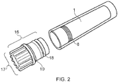
- an RFID cap 10 for a cryogenic vial 1 comprising a cap body 11 and an RFID tag 12 attached to the cap body 11.
- the RFID tag 12 includes an RFID chip 13 and an antenna 14 connected to the RFID chip 13.
- a support medium 15 supports the chip 13 and antenna 14 in their connected configuration.
- the chip 13 of the antenna is located inside coils of the antenna.
- the support medium is an encapsulating body which encapsulates the chip 13 and antenna 14.
- the encapsulating body takes the form of a solid disc.
- the cap body 11 of the RFID cap 10 includes a top portion 17 and a wall 16 extending away from the top portion.
- the RFID tag 12 is located at the top portion of the cap body 11.
- the RFID tag is attached to the inner surface of the cap at the top portion of the cap body.
- the cap body is made of transparent material, the RFID tag 11 is visible in Figure 1a when the external surface of the RFID cap is viewed from above.
- top and bottom are meant to have their usual meaning.
- the bottom of the RFID cap is the end of the cap in contact with the vial 1
- the top portion of the RFID cap is the end of the cap which is furthest from the vial 1.
- the wall 16 is cylindrical and includes attachment means 18 located at the bottom of the RFID cap.
- the attachment means 18 are configured to engage corresponding attachment means 8 on the cryogenic vial so that when the cap is used to tag the cryogenic vial 1, the RFID cap 11 is attached to the cryogenic vial 1 directly.
- the attachment means is a screw thread on the external surface of the cap body, the screw thread being configured to engage a corresponding screw thread on the internal surface of the cryogenic vial.
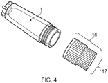
- a second RFID cap 20 is shown in figures 3 and 4 , where like reference numerals correspond to the same features as those described in relation to Figures 1a, 1b and 2 .
- the second RIFD cap 20 differs from the first in that the attachment means 19 (in the form of a screw thread) is located on the inside surface of the cap body 11 rather than the outside surface.
- the attachment means is a screw thread.
- other types of attachment means such as protrusions or grooves could be located on the inside surface or outside surface of the cap body instead of a screw thread.
- a third RFID cap 30 is shown in Figure 5 .
- the RFID cap 30 is configured to engage a cap 2 of a sealed cryogenic vial 1 so that, in use, the RFID cap 30 is attached to the cryogenic vial via the (original) cap 2 rather than attaching directly to the vial 1.
- the RFID cap of the third example includes a cap body 11 and an RFID tag 12 attached to the cap body 11.
- the RFID tag 12 includes an RFID chip 13 and an antenna (not shown in Figure 5 ) connected to the RFID chip 13.
- the cap body 11 of the RFID cap 30 includes a top portion and a wall extending away from the top portion.
- the RFID tag 12 is located at the top portion of the cap body 11.
- Protrusions 39 protrude from the wall of the cap body 11 to form a clip which acts as an attachment means.
- the protrusions 39 engage the underside of the cap 2 thereby holding the RFID cap 30 in place over the cap 2.
- the clip may form an irreversible connection between the RFID cap 30 and the cap 2.
- the central axis of the RFID tag 12 is aligned with the central axis of the cap 2 and therefore with the central axis X-X' of the cryogenic vial 1.
- a fourth RFID cap 40 is shown in Figure 6 .
- the top portion of the cap body 40 includes positioning elements 44 to align the RFID tag with the central axis of the cap.
- positioning elements 44 to align the RFID tag with the central axis of the cap.
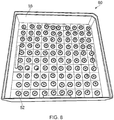
- Figure 7 shows a known standardized storage box 50 having an array of storage slots 56, each slot being capable of receiving a cryogenic vial.
- the storage box shown in Figure 7 includes 100 slots arranged in a 10x10 array.
- a box lid is used to cover the storage box.
- the box lid includes a grid of identification numbers 57, each identification number 57 being aligned with a slot 56 in the storage box when the lid is in use.
- FIG 8 shows an RFID box lid 60 according to the present invention, the RFID box lid being suitable for use with a standardized storage box such as that shown in Figure 7 .
- the RFID box lid 60 comprises a box lid body 55 and an array of RFID tags 52, each RFID tag 52 being positioned on the box lid such that when the box lid is in use covering the storage box, the RFID tag is aligned with a storage slot in the box for a cryogenic vial. Each RFID tag therefore acts as an identification reference for the sample located in the slot with which it is aligned.
- the box lid body of the RFID box lid includes an array of cylindrical recesses, each recess configured to receive a disc-shaped RFID tag.
- the RFID tags may be held in place by a layer or film of polypropylene attached over the array of recesses and RFID tags therein.
- the RFID cap 100 includes a cap body 111 and an RFID tag 112.
- the RFID tag 112 includes an RFID chip 113 and an antenna 114 connected to the RFID chip 113.
- a support medium 115 supports the chip 113 and antenna 114 in their connected configuration.
- the antenna is a loop antenna wound around a ferrite core 116 and the chip 113 of the RFID tag is located at one side of the coils of the antenna.
- the support medium 115 is an encapsulating body which encapsulates the chip 113 and antenna 114.
- the RFID cap 100 is an insert with a cap body 111 which is locatable inside the cryogenic vial 200 as indicated by the arrow in Figure 9 .
- Epoxy may be used to bond the RFID cap/RFID insert to the vial (tube).
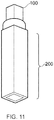
- Figure 11 shows the RFID cap and cryogenic vial of Figures 9 and 10 , when the RFID cap/ RFID insert is located inside the cryogenic vial.
- the cap body 111 of the RFID cap 100 is shaped to fit into a specific cryogenic vial.
- cryogenic vial shown in Figures 9-11 is an industry standard "384 tube”.
- the cap body 111 of the RFID cap 100 may formed by the support medium 115.
- the cap body 111 may be formed of a different material to the support medium.
- the cap body 111 may be manufactured separately to the cryogenic vial and then fitted into the vial as shown in Figures 9 and 10 .
- the cap 100 may be formed by placing the RFID tag 112 into a cryogenic vial 200 and then pouring an encapsulating material such as epoxy into the vial which then sets to form the support medium of the RFID cap.
- the support medium itself forms the cap body.
- the upmost part of the RFID cap is shaped such that when the RFID cap is inside the cryogenic vial, the upmost part of the RFID cap is either level with or below the top of the vial.
- the RFID cap includes the features discussed in relation to the example shown in Figures 9-11 . However, unlike the example shown in Figure 11 , the RFID cap 100 does not protrude from the vial 200 when it is placed inside of the vial.
- the antenna is positioned so that when the RFID cap is placed inside a cryogenic vial, the central axis of the antenna is at an angle to the longitudinal axis of the cryogenic vial.
- the antenna may be positioned such that its central axis is transverse to the longitudinal axis of the vial. In this way, the looped antenna will be "looking outwardly" from the side of the cryogenic vial, rather than looking along the longitudinal axis of the vial as in Figures 9-11 .
- the antenna may be formed by printing onto a circuit board (PCB).
- An antenna is preferably a "spiral" antenna.
- a PCB antenna may be made up of a single spiral but may take the form of a multilayer antenna which includes a first spiral antenna on a first PCB layer and a second spiral antenna on a second PCB layer.
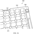
- a box 300 suitable for storing cryogenic vials which includes a cryogenic vial 200 and RFID cap 100 as shown in Figures 9-11 .
- Figures 12 and 13 show a top view of the box without the RFID cap
- Figures 14 and 15 show a top view of the box with the RFID cap
- Figures 16 and 17 show the box including the cryogenic vial 200 (and RFID cap 100) as viewed from underneath.
- the box 300 includes a plurality of slots 301 for receiving cryogenic vials 200.
- the plurality of slots 301 are arranged in an 8x12 array.
- the array of slots 301 are surrounded by an outer perimeter of the box 330 and an extra slot 302 is positioned on this perimeter 330 of the box 300.
- Cryogenic vial 200 (which includes RFID cap 100) is located in this extra slot. In this way, the box can be provided with RFID identification whilst keeping all slots in the array of slots free to be used to store vials which contain a sample.
- the box may include an alternate array of slots with any number nxm of slots.
- the RFID cap is shaped such that when it is inside the cryogenic vial, the upmost part of the RFID cap is level with or below the top of the vial.
- the box includes the features discussed in relation to the embodiment shown in Figures 12 and 13 .
- the RFID cap 100 does not protrude from the vial 200 when it is placed inside of the vial. This means that the RFID cap of a cryogenic vial located in one of the slots of the box will not protrude above the upper surface of the box as is the case for the box shown in Figures 14 and 15 .
Claims (10)
- Couvercle de boîte RFID (60) pour une boîte de stockage de flacons cryogéniques (50) ayant une matrice de fentes de stockage (56) pouvant recevoir des flacons cryogéniques (1) ; le couvercle de boîte RFID (60) comprenant :un corps de couvercle de boîte (55) ; etune matrice d'étiquettes RFID (52) positionnées sur le couvercle de boîte (60) de telle sorte que lorsque le couvercle de boîte (60) est positionné sur la boîte de stockage (50), chaque étiquette RFID (52) de la matrice est alignée avec une fente de stockage (56) dans la boîte (50).
- Couvercle de boîte RFID (60) selon la revendication 1, dans lequel la matrice d'étiquettes RFID (52) est une matrice 10x10.
- Couvercle de boîte RFID (60) selon la revendication 1 ou la revendication 2, dans lequel des étiquettes RFID adjacentes (52) dans la matrice ont un espacement de centre à centre qui n'est pas supérieur à 25 mm.
- Couvercle de boîte RFID (60) selon la revendication 3, dans lequel des étiquettes RFID adjacentes (52) dans la matrice ont un espacement de centre à centre qui n'est pas supérieur à 13 mm.
- Couvercle de boîte RFID (60) selon l'une quelconque des revendications 1 à 4, dans lequel chaque étiquette RFID (52) de la matrice est montée directement sur le corps de couvercle de boîte (55).
- Couvercle de boîte RFID (60) selon l'une quelconque des revendications 1 à 4, dans lequel chaque étiquette RFID (52) de la matrice est montée sur un film ; et dans lequel le film fixe la matrice au corps de couvercle de boîte (55).
- Film comprenant une matrice d'étiquettes RFID (52) à utiliser dans la boîte RFID selon la revendication 6.
- Film selon la revendication 7, dans lequel la matrice d'étiquettes RFID (52) est une matrice 10x10.
- Film selon l'une quelconque des revendications 6 à 8, dans lequel des étiquettes RFID adjacentes (52) dans la matrice ont un espacement de centre à centre qui n'est pas supérieur à 25 mm.
- Film selon la revendication 9, dans lequel les étiquettes RFID adjacentes (52) dans la matrice ont un espacement centre à centre qui n'est pas supérieur à 13 mm.
Priority Applications (2)
| Application Number | Priority Date | Filing Date | Title |
|---|---|---|---|
| EP19192914.0A EP3633556B1 (fr) | 2013-03-08 | 2014-03-07 | Capuchons rfid |
| DK19192914.0T DK3633556T3 (da) | 2013-03-08 | 2014-03-07 | RFID-hætte |
Applications Claiming Priority (3)
| Application Number | Priority Date | Filing Date | Title |
|---|---|---|---|
| GBGB1304369.0A GB201304369D0 (en) | 2013-03-08 | 2013-03-08 | Rfid caps and lids |
| GBGB1305973.8A GB201305973D0 (en) | 2013-03-08 | 2013-04-03 | RFID caps and lips |
| PCT/GB2014/050675 WO2014135890A1 (fr) | 2013-03-08 | 2014-03-07 | Bouchons et couvercles rfid |
Related Child Applications (2)
| Application Number | Title | Priority Date | Filing Date |
|---|---|---|---|
| EP19192914.0A Division EP3633556B1 (fr) | 2013-03-08 | 2014-03-07 | Capuchons rfid |
| EP19192914.0A Division-Into EP3633556B1 (fr) | 2013-03-08 | 2014-03-07 | Capuchons rfid |
Publications (2)
| Publication Number | Publication Date |
|---|---|
| EP2965266A1 EP2965266A1 (fr) | 2016-01-13 |
| EP2965266B1 true EP2965266B1 (fr) | 2019-10-02 |
Family
ID=48189725
Family Applications (2)
| Application Number | Title | Priority Date | Filing Date |
|---|---|---|---|
| EP19192914.0A Active EP3633556B1 (fr) | 2013-03-08 | 2014-03-07 | Capuchons rfid |
| EP14710359.2A Active EP2965266B1 (fr) | 2013-03-08 | 2014-03-07 | Bouchons et couvercles rfid |
Family Applications Before (1)
| Application Number | Title | Priority Date | Filing Date |
|---|---|---|---|
| EP19192914.0A Active EP3633556B1 (fr) | 2013-03-08 | 2014-03-07 | Capuchons rfid |
Country Status (7)
| Country | Link |
|---|---|
| US (1) | US10748050B2 (fr) |
| EP (2) | EP3633556B1 (fr) |
| DK (2) | DK2965266T3 (fr) |
| ES (2) | ES2906461T3 (fr) |
| GB (2) | GB201304369D0 (fr) |
| PT (2) | PT2965266T (fr) |
| WO (1) | WO2014135890A1 (fr) |
Cited By (5)
| Publication number | Priority date | Publication date | Assignee | Title |
|---|---|---|---|---|
| US10973226B2 (en) | 2018-10-05 | 2021-04-13 | TMRW Life Sciences, Inc. | Apparatus to preserve and identify biological samples at cryogenic conditions |
| USD963194S1 (en) | 2020-12-09 | 2022-09-06 | TMRW Life Sciences, Inc. | Cryogenic vial carrier |
| US11607691B2 (en) | 2019-10-29 | 2023-03-21 | TMRW Life Sciences, Inc. | Apparatus to facilitate transfer of biological specimens stored at cryogenic conditions |
| US11632949B2 (en) | 2020-09-24 | 2023-04-25 | TMRW Life Sciences, Inc. | Cryogenic storage system with sensors to measure one or more parameters therewithin |
| US11817187B2 (en) | 2020-05-18 | 2023-11-14 | TMRW Life Sciences, Inc. | Handling and tracking of biological specimens for cryogenic storage |
Families Citing this family (15)
| Publication number | Priority date | Publication date | Assignee | Title |
|---|---|---|---|---|
| US20160236387A1 (en) * | 2013-11-15 | 2016-08-18 | Parker-Hannifin Corporation | Rfid enabled container |
| WO2016081755A1 (fr) * | 2014-11-19 | 2016-05-26 | Laboratory Corporation Of America Holdings | Dispositif de collecte d'échantillons avec capuchon rfid et dispositifs de verrouillage dans un bloc de test |
| CN105590081B (zh) * | 2016-03-15 | 2021-07-27 | 广州佰迈起生物科技有限公司 | 一种射频识别标签读取系统、读写设备及读取方法 |
| JP6954728B2 (ja) * | 2016-09-13 | 2021-10-27 | 株式会社77Kc | 凍結保存容器 |
| JP6954729B2 (ja) * | 2016-09-13 | 2021-10-27 | 株式会社77Kc | 個体管理システム |
| CN106560419B (zh) * | 2016-11-14 | 2018-10-19 | 上海原能细胞医学技术有限公司 | 管阵式液氮罐 |
| US10745186B2 (en) | 2017-05-09 | 2020-08-18 | Fibulas, Inc. | Container for biological preservation at low temperature |
| US20180368394A1 (en) * | 2017-06-27 | 2018-12-27 | Inteli-Straw, LLC | Semen/gamete and embryo storage receptacles with rfid data identification |
| WO2019018837A1 (fr) * | 2017-07-21 | 2019-01-24 | Avery Dennison Retail Information Services Llc | Suivi de flacon rfid avec une incrustation rfid |
| CN111771211A (zh) * | 2017-12-28 | 2020-10-13 | 艾利丹尼森零售信息服务公司 | Rfid启用、标签标记和跟踪需要在低温状态下保存的物品的系统和方法 |
| US11279499B2 (en) * | 2020-01-03 | 2022-03-22 | The Boeing Company | Increased visibility of indicating markers in a structure and associated system and method |
| USD951481S1 (en) | 2020-09-01 | 2022-05-10 | TMRW Life Sciences, Inc. | Cryogenic vial |
| DE102020133546A1 (de) * | 2020-12-15 | 2022-06-15 | Schreiner Group Gmbh & Co. Kg | Elektronische Etikettieranordnung für ein mehrteiliges Gefäß, System und Verfahren zum Anbringen einer elektronischen Etikettieranordnung an einem mehrteiligen Gefäß |
| WO2023161967A1 (fr) * | 2022-02-25 | 2023-08-31 | ILIP S.r.l. | Système rfid et procédé de surveillance du degré de maturité d'une pluralité de fruits |
| US11937597B1 (en) | 2023-04-19 | 2024-03-26 | Biotech, Inc. | Cryopreservation device with integrated tracking device chamber |
Family Cites Families (14)
| Publication number | Priority date | Publication date | Assignee | Title |
|---|---|---|---|---|
| WO1996007479A1 (fr) * | 1994-09-09 | 1996-03-14 | Gay Freres Vente Et Exportation S.A. | Dispositif d'enregistrement et de transfert d'informations pour analyses en eprouvette |
| WO2003023706A1 (fr) | 2001-09-13 | 2003-03-20 | Alcoa Closure Systems International, Inc. | Procede de fabrication d'un conditionnement et d'un systeme de fermeture contenant des informations interactives |
| JP2005321935A (ja) * | 2004-05-07 | 2005-11-17 | Toyo Seikan Kaisha Ltd | Icタグ内蔵キャップ |
| US20060065670A1 (en) * | 2004-09-21 | 2006-03-30 | Arjowiggins Security | Packaging device for dispensing security-protected units of product |
| JP2007041666A (ja) * | 2005-08-01 | 2007-02-15 | Ricoh Co Ltd | Rfidタグ及びその製造方法 |
| US8346382B2 (en) * | 2005-08-25 | 2013-01-01 | Coldtrack, Llc | Hierarchical sample storage system |
| US8388905B2 (en) * | 2006-03-13 | 2013-03-05 | Nipro Diagnostics, Inc. | Method and apparatus for coding diagnostic meters |
| JP4840917B2 (ja) | 2006-07-12 | 2011-12-21 | 日本クラウンコルク株式会社 | Icタグ付蓋体 |
| US8152367B2 (en) * | 2007-05-04 | 2012-04-10 | Sealed Air Corporation (Us) | Insulated container having a temperature monitoring device |
| EP2301857B1 (fr) | 2008-06-20 | 2012-08-29 | Toyo Seikan Kaisha, Ltd. | Capuchon de résine muni d'une étiquette à circuit intégré |
| US20100141384A1 (en) * | 2008-12-04 | 2010-06-10 | Yeh-Shun Chen | Bottle cap having anti-counterfeit function and bottle using the same |
| US8872627B2 (en) * | 2010-02-12 | 2014-10-28 | Biotillion, Llc | Tracking biological and other samples using RFID tags |
| US9289770B2 (en) * | 2010-02-27 | 2016-03-22 | Lear Lavi | RFID—specimen transport puck process features and process method to efficiently wand, rack, transport, track specimens in the laboratory |
| DE102010012375B4 (de) | 2010-03-22 | 2012-02-09 | Sim Scientific Instruments Manufacturer Gmbh | Transportkappe |
-
2013
- 2013-03-08 GB GBGB1304369.0A patent/GB201304369D0/en not_active Ceased
- 2013-04-03 GB GBGB1305973.8A patent/GB201305973D0/en not_active Ceased
-
2014
- 2014-03-07 ES ES19192914T patent/ES2906461T3/es active Active
- 2014-03-07 PT PT147103592T patent/PT2965266T/pt unknown
- 2014-03-07 EP EP19192914.0A patent/EP3633556B1/fr active Active
- 2014-03-07 US US14/772,743 patent/US10748050B2/en active Active
- 2014-03-07 DK DK14710359T patent/DK2965266T3/da active
- 2014-03-07 PT PT191929140T patent/PT3633556T/pt unknown
- 2014-03-07 EP EP14710359.2A patent/EP2965266B1/fr active Active
- 2014-03-07 ES ES14710359T patent/ES2760022T3/es active Active
- 2014-03-07 DK DK19192914.0T patent/DK3633556T3/da active
- 2014-03-07 WO PCT/GB2014/050675 patent/WO2014135890A1/fr active Application Filing
Non-Patent Citations (1)
| Title |
|---|
| None * |
Cited By (7)
| Publication number | Priority date | Publication date | Assignee | Title |
|---|---|---|---|---|
| US10973226B2 (en) | 2018-10-05 | 2021-04-13 | TMRW Life Sciences, Inc. | Apparatus to preserve and identify biological samples at cryogenic conditions |
| US11252956B2 (en) | 2018-10-05 | 2022-02-22 | TMRW Life Sciences, Inc. | Apparatus to preserve and identify biological samples at cryogenic conditions |
| US11607691B2 (en) | 2019-10-29 | 2023-03-21 | TMRW Life Sciences, Inc. | Apparatus to facilitate transfer of biological specimens stored at cryogenic conditions |
| US11817187B2 (en) | 2020-05-18 | 2023-11-14 | TMRW Life Sciences, Inc. | Handling and tracking of biological specimens for cryogenic storage |
| US11632949B2 (en) | 2020-09-24 | 2023-04-25 | TMRW Life Sciences, Inc. | Cryogenic storage system with sensors to measure one or more parameters therewithin |
| USD963194S1 (en) | 2020-12-09 | 2022-09-06 | TMRW Life Sciences, Inc. | Cryogenic vial carrier |
| USD1002868S1 (en) | 2020-12-09 | 2023-10-24 | TMRW Life Sciences, Inc. | Cryogenic vial carrier |
Also Published As
| Publication number | Publication date |
|---|---|
| US10748050B2 (en) | 2020-08-18 |
| EP3633556A1 (fr) | 2020-04-08 |
| PT2965266T (pt) | 2019-12-17 |
| GB201304369D0 (en) | 2013-04-24 |
| WO2014135890A1 (fr) | 2014-09-12 |
| GB201305973D0 (en) | 2013-05-15 |
| EP3633556B1 (fr) | 2022-01-19 |
| ES2760022T3 (es) | 2020-05-12 |
| PT3633556T (pt) | 2022-02-15 |
| DK2965266T3 (da) | 2019-12-09 |
| ES2906461T3 (es) | 2022-04-18 |
| DK3633556T3 (da) | 2022-01-31 |
| EP2965266A1 (fr) | 2016-01-13 |
| US20160026911A1 (en) | 2016-01-28 |
Similar Documents
| Publication | Publication Date | Title |
|---|---|---|
| EP2965266B1 (fr) | Bouchons et couvercles rfid | |
| EP2948247B1 (fr) | Étiquette rfid | |
| EP2866938B1 (fr) | Étiquette rfid pour paillettes cryogéniques | |
| US10973226B2 (en) | Apparatus to preserve and identify biological samples at cryogenic conditions | |
| US9619678B2 (en) | RFID interrogation probe | |
| US9418265B2 (en) | RFID reader having an array of antennas | |
| ES2467465B1 (es) | Etiqueta de rfid, systema y procedimiento para la identificación de muestras a temperaturas criogénicas | |
| EP2743865B1 (fr) | Étiquette RFID, système et procédé d'identification d'échantillons à des températures cryogéniques | |
| US20220388005A1 (en) | Rfid enabled specimen holder |
Legal Events
| Date | Code | Title | Description |
|---|---|---|---|
| PUAI | Public reference made under article 153(3) epc to a published international application that has entered the european phase |
Free format text: ORIGINAL CODE: 0009012 |
|
| 17P | Request for examination filed |
Effective date: 20151007 |
|
| AK | Designated contracting states |
Kind code of ref document: A1 Designated state(s): AL AT BE BG CH CY CZ DE DK EE ES FI FR GB GR HR HU IE IS IT LI LT LU LV MC MK MT NL NO PL PT RO RS SE SI SK SM TR |
|
| AX | Request for extension of the european patent |
Extension state: BA ME |
|
| DAX | Request for extension of the european patent (deleted) | ||
| GRAP | Despatch of communication of intention to grant a patent |
Free format text: ORIGINAL CODE: EPIDOSNIGR1 |
|
| STAA | Information on the status of an ep patent application or granted ep patent |
Free format text: STATUS: GRANT OF PATENT IS INTENDED |
|
| INTG | Intention to grant announced |
Effective date: 20190415 |
|
| RAP1 | Party data changed (applicant data changed or rights of an application transferred) |
Owner name: CRYOGATT SYSTEMS LIMITED |
|
| GRAS | Grant fee paid |
Free format text: ORIGINAL CODE: EPIDOSNIGR3 |
|
| GRAA | (expected) grant |
Free format text: ORIGINAL CODE: 0009210 |
|
| STAA | Information on the status of an ep patent application or granted ep patent |
Free format text: STATUS: THE PATENT HAS BEEN GRANTED |
|
| AK | Designated contracting states |
Kind code of ref document: B1 Designated state(s): AL AT BE BG CH CY CZ DE DK EE ES FI FR GB GR HR HU IE IS IT LI LT LU LV MC MK MT NL NO PL PT RO RS SE SI SK SM TR |
|
| REG | Reference to a national code |
Ref country code: GB Ref legal event code: FG4D |
|
| REG | Reference to a national code |
Ref country code: CH Ref legal event code: EP Ref country code: AT Ref legal event code: REF Ref document number: 1187002 Country of ref document: AT Kind code of ref document: T Effective date: 20191015 |
|
| REG | Reference to a national code |
Ref country code: DE Ref legal event code: R096 Ref document number: 602014054503 Country of ref document: DE |
|
| REG | Reference to a national code |
Ref country code: IE Ref legal event code: FG4D |
|
| REG | Reference to a national code |
Ref country code: DK Ref legal event code: T3 Effective date: 20191203 |
|
| REG | Reference to a national code |
Ref country code: PT Ref legal event code: SC4A Ref document number: 2965266 Country of ref document: PT Date of ref document: 20191217 Kind code of ref document: T Free format text: AVAILABILITY OF NATIONAL TRANSLATION Effective date: 20191204 |
|
| REG | Reference to a national code |
Ref country code: SE Ref legal event code: TRGR |
|
| REG | Reference to a national code |
Ref country code: NL Ref legal event code: FP |
|
| REG | Reference to a national code |
Ref country code: NO Ref legal event code: T2 Effective date: 20191002 |
|
| REG | Reference to a national code |
Ref country code: LT Ref legal event code: MG4D |
|
| REG | Reference to a national code |
Ref country code: AT Ref legal event code: MK05 Ref document number: 1187002 Country of ref document: AT Kind code of ref document: T Effective date: 20191002 |
|
| REG | Reference to a national code |
Ref country code: GR Ref legal event code: EP Ref document number: 20190403868 Country of ref document: GR Effective date: 20200318 |
|
| PG25 | Lapsed in a contracting state [announced via postgrant information from national office to epo] |
Ref country code: AT Free format text: LAPSE BECAUSE OF FAILURE TO SUBMIT A TRANSLATION OF THE DESCRIPTION OR TO PAY THE FEE WITHIN THE PRESCRIBED TIME-LIMIT Effective date: 20191002 Ref country code: PL Free format text: LAPSE BECAUSE OF FAILURE TO SUBMIT A TRANSLATION OF THE DESCRIPTION OR TO PAY THE FEE WITHIN THE PRESCRIBED TIME-LIMIT Effective date: 20191002 Ref country code: LT Free format text: LAPSE BECAUSE OF FAILURE TO SUBMIT A TRANSLATION OF THE DESCRIPTION OR TO PAY THE FEE WITHIN THE PRESCRIBED TIME-LIMIT Effective date: 20191002 Ref country code: BG Free format text: LAPSE BECAUSE OF FAILURE TO SUBMIT A TRANSLATION OF THE DESCRIPTION OR TO PAY THE FEE WITHIN THE PRESCRIBED TIME-LIMIT Effective date: 20200102 Ref country code: LV Free format text: LAPSE BECAUSE OF FAILURE TO SUBMIT A TRANSLATION OF THE DESCRIPTION OR TO PAY THE FEE WITHIN THE PRESCRIBED TIME-LIMIT Effective date: 20191002 |
|
| REG | Reference to a national code |
Ref country code: ES Ref legal event code: FG2A Ref document number: 2760022 Country of ref document: ES Kind code of ref document: T3 Effective date: 20200512 |
|
| PG25 | Lapsed in a contracting state [announced via postgrant information from national office to epo] |
Ref country code: HR Free format text: LAPSE BECAUSE OF FAILURE TO SUBMIT A TRANSLATION OF THE DESCRIPTION OR TO PAY THE FEE WITHIN THE PRESCRIBED TIME-LIMIT Effective date: 20191002 Ref country code: RS Free format text: LAPSE BECAUSE OF FAILURE TO SUBMIT A TRANSLATION OF THE DESCRIPTION OR TO PAY THE FEE WITHIN THE PRESCRIBED TIME-LIMIT Effective date: 20191002 Ref country code: IS Free format text: LAPSE BECAUSE OF FAILURE TO SUBMIT A TRANSLATION OF THE DESCRIPTION OR TO PAY THE FEE WITHIN THE PRESCRIBED TIME-LIMIT Effective date: 20200224 Ref country code: CZ Free format text: LAPSE BECAUSE OF FAILURE TO SUBMIT A TRANSLATION OF THE DESCRIPTION OR TO PAY THE FEE WITHIN THE PRESCRIBED TIME-LIMIT Effective date: 20191002 |
|
| PG25 | Lapsed in a contracting state [announced via postgrant information from national office to epo] |
Ref country code: AL Free format text: LAPSE BECAUSE OF FAILURE TO SUBMIT A TRANSLATION OF THE DESCRIPTION OR TO PAY THE FEE WITHIN THE PRESCRIBED TIME-LIMIT Effective date: 20191002 |
|
| REG | Reference to a national code |
Ref country code: DE Ref legal event code: R097 Ref document number: 602014054503 Country of ref document: DE |
|
| PG2D | Information on lapse in contracting state deleted |
Ref country code: IS |
|
| PG25 | Lapsed in a contracting state [announced via postgrant information from national office to epo] |
Ref country code: RO Free format text: LAPSE BECAUSE OF FAILURE TO SUBMIT A TRANSLATION OF THE DESCRIPTION OR TO PAY THE FEE WITHIN THE PRESCRIBED TIME-LIMIT Effective date: 20191002 Ref country code: EE Free format text: LAPSE BECAUSE OF FAILURE TO SUBMIT A TRANSLATION OF THE DESCRIPTION OR TO PAY THE FEE WITHIN THE PRESCRIBED TIME-LIMIT Effective date: 20191002 Ref country code: IS Free format text: LAPSE BECAUSE OF FAILURE TO SUBMIT A TRANSLATION OF THE DESCRIPTION OR TO PAY THE FEE WITHIN THE PRESCRIBED TIME-LIMIT Effective date: 20200202 |
|
| PLBE | No opposition filed within time limit |
Free format text: ORIGINAL CODE: 0009261 |
|
| STAA | Information on the status of an ep patent application or granted ep patent |
Free format text: STATUS: NO OPPOSITION FILED WITHIN TIME LIMIT |
|
| PG25 | Lapsed in a contracting state [announced via postgrant information from national office to epo] |
Ref country code: SK Free format text: LAPSE BECAUSE OF FAILURE TO SUBMIT A TRANSLATION OF THE DESCRIPTION OR TO PAY THE FEE WITHIN THE PRESCRIBED TIME-LIMIT Effective date: 20191002 Ref country code: SM Free format text: LAPSE BECAUSE OF FAILURE TO SUBMIT A TRANSLATION OF THE DESCRIPTION OR TO PAY THE FEE WITHIN THE PRESCRIBED TIME-LIMIT Effective date: 20191002 |
|
| 26N | No opposition filed |
Effective date: 20200703 |
|
| PG25 | Lapsed in a contracting state [announced via postgrant information from national office to epo] |
Ref country code: MC Free format text: LAPSE BECAUSE OF FAILURE TO SUBMIT A TRANSLATION OF THE DESCRIPTION OR TO PAY THE FEE WITHIN THE PRESCRIBED TIME-LIMIT Effective date: 20191002 |
|
| PG25 | Lapsed in a contracting state [announced via postgrant information from national office to epo] |
Ref country code: SI Free format text: LAPSE BECAUSE OF FAILURE TO SUBMIT A TRANSLATION OF THE DESCRIPTION OR TO PAY THE FEE WITHIN THE PRESCRIBED TIME-LIMIT Effective date: 20191002 |
|
| PG25 | Lapsed in a contracting state [announced via postgrant information from national office to epo] |
Ref country code: LU Free format text: LAPSE BECAUSE OF NON-PAYMENT OF DUE FEES Effective date: 20200307 |
|
| PG25 | Lapsed in a contracting state [announced via postgrant information from national office to epo] |
Ref country code: TR Free format text: LAPSE BECAUSE OF FAILURE TO SUBMIT A TRANSLATION OF THE DESCRIPTION OR TO PAY THE FEE WITHIN THE PRESCRIBED TIME-LIMIT Effective date: 20191002 Ref country code: MT Free format text: LAPSE BECAUSE OF FAILURE TO SUBMIT A TRANSLATION OF THE DESCRIPTION OR TO PAY THE FEE WITHIN THE PRESCRIBED TIME-LIMIT Effective date: 20191002 Ref country code: CY Free format text: LAPSE BECAUSE OF FAILURE TO SUBMIT A TRANSLATION OF THE DESCRIPTION OR TO PAY THE FEE WITHIN THE PRESCRIBED TIME-LIMIT Effective date: 20191002 |
|
| PGFP | Annual fee paid to national office [announced via postgrant information from national office to epo] |
Ref country code: NL Payment date: 20220224 Year of fee payment: 9 Ref country code: IT Payment date: 20220224 Year of fee payment: 9 Ref country code: BE Payment date: 20220228 Year of fee payment: 9 |
|
| PG25 | Lapsed in a contracting state [announced via postgrant information from national office to epo] |
Ref country code: MK Free format text: LAPSE BECAUSE OF FAILURE TO SUBMIT A TRANSLATION OF THE DESCRIPTION OR TO PAY THE FEE WITHIN THE PRESCRIBED TIME-LIMIT Effective date: 20191002 |
|
| PGFP | Annual fee paid to national office [announced via postgrant information from national office to epo] |
Ref country code: ES Payment date: 20220401 Year of fee payment: 9 |
|
| PGFP | Annual fee paid to national office [announced via postgrant information from national office to epo] |
Ref country code: NO Payment date: 20230224 Year of fee payment: 10 Ref country code: IE Payment date: 20230223 Year of fee payment: 10 Ref country code: FR Payment date: 20230223 Year of fee payment: 10 Ref country code: FI Payment date: 20230224 Year of fee payment: 10 Ref country code: DK Payment date: 20230224 Year of fee payment: 10 |
|
| PGFP | Annual fee paid to national office [announced via postgrant information from national office to epo] |
Ref country code: SE Payment date: 20230223 Year of fee payment: 10 Ref country code: PT Payment date: 20230208 Year of fee payment: 10 Ref country code: GR Payment date: 20230207 Year of fee payment: 10 Ref country code: GB Payment date: 20230221 Year of fee payment: 10 Ref country code: DE Payment date: 20230223 Year of fee payment: 10 |
|
| PGFP | Annual fee paid to national office [announced via postgrant information from national office to epo] |
Ref country code: CH Payment date: 20230401 Year of fee payment: 10 |
|
| REG | Reference to a national code |
Ref country code: NL Ref legal event code: MM Effective date: 20230401 |
|
| REG | Reference to a national code |
Ref country code: BE Ref legal event code: MM Effective date: 20230331 |
|
| PG25 | Lapsed in a contracting state [announced via postgrant information from national office to epo] |
Ref country code: NL Free format text: LAPSE BECAUSE OF NON-PAYMENT OF DUE FEES Effective date: 20230401 |
|
| PG25 | Lapsed in a contracting state [announced via postgrant information from national office to epo] |
Ref country code: BE Free format text: LAPSE BECAUSE OF NON-PAYMENT OF DUE FEES Effective date: 20230331 |