EP2964548B1 - Artikelaufbewahrungs-, -ausgabe- und -empfangssystem, -vorrichtung, -verfahren und -anwendungen - Google Patents
Artikelaufbewahrungs-, -ausgabe- und -empfangssystem, -vorrichtung, -verfahren und -anwendungen Download PDFInfo
- Publication number
- EP2964548B1 EP2964548B1 EP14760119.9A EP14760119A EP2964548B1 EP 2964548 B1 EP2964548 B1 EP 2964548B1 EP 14760119 A EP14760119 A EP 14760119A EP 2964548 B1 EP2964548 B1 EP 2964548B1
- Authority
- EP
- European Patent Office
- Prior art keywords
- conveyance
- mechanisms
- conveyance mechanisms
- bridge
- disposed
- Prior art date
- Legal status (The legal status is an assumption and is not a legal conclusion. Google has not performed a legal analysis and makes no representation as to the accuracy of the status listed.)
- Not-in-force
Links
Images




Classifications
-
- B—PERFORMING OPERATIONS; TRANSPORTING
- B65—CONVEYING; PACKING; STORING; HANDLING THIN OR FILAMENTARY MATERIAL
- B65G—TRANSPORT OR STORAGE DEVICES, e.g. CONVEYORS FOR LOADING OR TIPPING, SHOP CONVEYOR SYSTEMS OR PNEUMATIC TUBE CONVEYORS
- B65G1/00—Storing articles, individually or in orderly arrangement, in warehouses or magazines
- B65G1/02—Storage devices
- B65G1/04—Storage devices mechanical
- B65G1/0471—Storage devices mechanical with access from beneath
-
- B—PERFORMING OPERATIONS; TRANSPORTING
- B65—CONVEYING; PACKING; STORING; HANDLING THIN OR FILAMENTARY MATERIAL
- B65G—TRANSPORT OR STORAGE DEVICES, e.g. CONVEYORS FOR LOADING OR TIPPING, SHOP CONVEYOR SYSTEMS OR PNEUMATIC TUBE CONVEYORS
- B65G1/00—Storing articles, individually or in orderly arrangement, in warehouses or magazines
- B65G1/02—Storage devices
-
- B—PERFORMING OPERATIONS; TRANSPORTING
- B65—CONVEYING; PACKING; STORING; HANDLING THIN OR FILAMENTARY MATERIAL
- B65G—TRANSPORT OR STORAGE DEVICES, e.g. CONVEYORS FOR LOADING OR TIPPING, SHOP CONVEYOR SYSTEMS OR PNEUMATIC TUBE CONVEYORS
- B65G1/00—Storing articles, individually or in orderly arrangement, in warehouses or magazines
- B65G1/02—Storage devices
- B65G1/026—Racks equipped with a displaceable load carrying surface to facilitate loading or unloading
-
- B—PERFORMING OPERATIONS; TRANSPORTING
- B65—CONVEYING; PACKING; STORING; HANDLING THIN OR FILAMENTARY MATERIAL
- B65G—TRANSPORT OR STORAGE DEVICES, e.g. CONVEYORS FOR LOADING OR TIPPING, SHOP CONVEYOR SYSTEMS OR PNEUMATIC TUBE CONVEYORS
- B65G1/00—Storing articles, individually or in orderly arrangement, in warehouses or magazines
- B65G1/02—Storage devices
- B65G1/04—Storage devices mechanical
- B65G1/0464—Storage devices mechanical with access from above
Definitions
- aspects and embodiments of the invention are directed to item handling systems, methods, and applications thereof. More particularly, a storage, dispensing, and receiving system and associated methods adapted for seismic sensors (nodes). Most particularly, a storage, dispensing, and receiving system and associated methods adapted for nodes in a marine environment.
- a seismic sensor ('node') handling system is described in co-owned US 8,087,848 .
- the '848 patent describes a node storage device comprised of a series of independently actuatable conveyor sections horizontally oriented one above the other at different, fixed heights above the back deck of the ship. These sub-systems are replicated side-by-side and end-to end so as to provide storage for, and more importantly fast access to, a large number of nodes.
- the speed with which nodes can be delivered to the node deployment/recovery workstation limits in part the maximum speed at which the entire node deployment/recovery operation can be conducted, including vessel speed.
- the main reason each node has a place on an independently actuatable conveyor is for speedy access and (horizontal) transit.
- S the sum of: 1) the height of the nodes; 2) the height of the conveyor machinery; and 3) space for the belt to traverse the return path beneath the conveyor machinery without interference.
- the conveyors and their related machinery may consume more space than the nodes themselves. This drastically reduces the density of node storage possible in a given space. For any given number of nodes this may require a larger vessel than might otherwise be necessary and the substantial cost associated therewith.
- node storage, dispensing, and receiving apparatus and method that maintains current or provides improved speed of access, and further provides higher storage density and reduced complexity and machinery to purchase, install, and maintain than available under the current state of the art.
- the term 'about' means the amount of the specified quantity plus/minus a fractional amount (e.g., ⁇ 10%, ⁇ 9%, ⁇ 8%, ⁇ 7%, ⁇ 6%, ⁇ 5%, ⁇ 4%, ⁇ 3%, ⁇ 2%, ⁇ 1%, etc.) thereof that a person skilled in the art would recognize as typical and reasonable for that particular quantity or measurement.
- a fractional amount e.g., ⁇ 10%, ⁇ 9%, ⁇ 8%, ⁇ 7%, ⁇ 6%, ⁇ 5%, ⁇ 4%, ⁇ 3%, ⁇ 2%, ⁇ 1%, etc.
- FR2294943 A1 discloses an item storage, dispensing, and receiving apparatus according to the preamble of claim 1 and relates to a temporary storage unit for ceramic tiles.
- the unit consists of a frame with vertical horizontal columns, having horizontal and parallel consoles, to support the tiles.
- the consoles are positioned along two vertical and opposite planes, to form a store, in which the tiles rest on the consoles with opposite side edges.
- the apparatus comprises a plurality of hanging arms (513) each pivotally connected at a region thereof to an activation member that is connected to the frame assembly, wherein each of the plurality of rails (511) is fixedly attached to a distal region of each of the hanging arms, further wherein at least portions of the side walls have cut-out regions such that, upon activation of the activation member, the rails are movable into and out of the cut-out regions such that the rails are, respectively, disposed out of or in the open space.
- An aspect is an item storage, dispensing, and receiving apparatus that includes a frame assembly having a height, H, and a length, L, including at least one section thereof having two opposing side wall sections, wherein each opposing side wall section includes a plurality of vertically spaced rails disposed on an inner surface thereof such that each rail on a respective side wall section is disposed opposite a corresponding rail on the opposing side wall section, further wherein the at least one section has an open space fully extending intermediate the plurality of vertically spaced rails between the two opposing side wall sections over the height H and the length L, and one or more conveyance mechanisms operatively disposed within the open space along at least a portion of the length L, wherein the one or more conveyance mechanisms are movable in a vertical direction traversing the open space along the height H.
- the method may include the following additional steps, features, limitations, and/or characteristics:
- An aspect of the invention is an item storage, dispensing, and receiving apparatus including a frame assembly having a height, H, and a length, L, including at least one section thereof having two opposing side wall sections, wherein each opposing side wall section includes a plurality of vertically spaced rails disposed on an inner surface thereof such that each rail on a respective side wall section is disposed opposite a corresponding rail on the opposing side wall section, further wherein the at least one section has an open space fully extending intermediate the plurality of vertically spaced rails between the two opposing side wall sections over the height H and the length L; a track disposed adjacent a top of the frame assembly over the open space along at least a portion of the length L; and a horizontal conveyance mechanism moveably coupled to the track, wherein the conveyance mechanism is further moveable in a vertical direction traversing the open space along the height H.
- the method may include the following additional steps, features, limitations, and/or characteristics:
- An aspect is an item moving method for moving at least one of a plurality of items vertically disposed in tiered, spaced relation including the steps of vertically moving an item conveyance mechanism from at least one of a position below a lowest tiered item until it engages the item and from a position above a highest tiered item until it engages the item; and horizontally conveying the engaged item to a location different than the horizontal engagement location of the item.
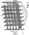
- Fig. 1 illustrates at least a portion (e.g., a section) of a rigid frame or rack 510 having no moving parts and constructed as indicated, looking much like a baker's rack; that is, a series of spaced vertical support members are connected by spaced horizontal supports 511 (e.g., angle iron geometry forming opposing walls, providing a solution to the aforementioned problems.
- the spaced horizontal supports include horizontal shelf sections 599 (see also Fig. 7a ) that can support an item (e.g., a node) at its edge (see also Fig. 7b ) and thus a plurality of items in a tiered fashion (five tiers shown in Fig. 1 for example only).
- the rack 510 may be made steady affixed to the floor or bottom of the ship deck, or to a bottom structure and at the top by an upper structure, e.g., an overhead deck (not shown).
- the rack 510 may be constructed of inexpensive metal angle and pipe, welded, or a suitable plastic or other material.
- the racks may be easily and inexpensively mass-produced.
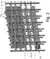
- Nodes 110 are supported on the horizontal supports 511 at their edges alone, the center of the rack, i.e., the space intermediate the opposing walls, being completely open as illustrated in Fig. 2 .
- a horizontal conveyance mechanism 520 e.g., a single conveyor belt as shown
- the horizontal supports 511 thus need be spaced no further apart than the nominal height of a node (or other 'item'), permitting much denser vertical storage than the belt-per-level arrangement in present systems such as described in the aforementioned US '848 patent.
- Each tier shares the same horizontal transport mechanism by virtue of the vertically repositionable conveyance mechanism 520, reducing by a factor of N (where N is number of tiers) the amount of transport machinery to purchase, install and maintain.
- N number of tiers
- vertical node density is increased approximately 1 + S/h. For example, node density on assignee's marine vessel was increased by a factor of 2.26; from 1800 nodes to over 4000.
- the horizontal conveyance mechanism 520 can be elevated to engage nodes on any tier.
- the elevation mechanism may be, e.g., one or more scissor jacks 530 as shown, but other elevating mechanisms could be used (covered subsequently).
- only a single vertically movable conveyance mechanism is disposed in the open space traversable by the respective one or more conveyance mechanisms; that is, for any given number of conveyance mechanisms disposed along the length of a rack or racks, only a single conveyance mechanism occupies the open space vertically serviceable by the given conveyance mechanism.
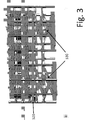
- Fig. 4 illustrates an in-line, end-to-end replication of racks 510a, 510b.
- activation of the belts will pass nodes from rack to rack and eventually off/on to/from the movable conveyor 232 (also called the bridge).
- Bridge 232 is adjustable through some angle ⁇ such that its first end 232a reaches all item tiers and allow the nodes to move from their storage level 515 to/from the working conveyor transport level 236 at the conveyor's second end 232b.
- the racks can be replicated side-by-side ( Fig. 5 ) wherein each row might share a transversely movable bridge 232 to carry nodes to the working transport level 236. Such pairs may be further replicated side-by-side with nominal intervening space for service access as illustrated in Fig. 6 .
- This rack replication pattern may be continued as required in both X and Y directions, where all rows are serviced by one or more movable bridges 232.
- the bridge conveyor(s) 232 take substantial space across the entire width of the vessel or area where the racks are located, whether laterally movable to service multiple racks or not.
- An alternative embodiment is illustrated with reference to Figs. 8 , 9 , 10 .
- the rack 510 is composed of horizontal angle support members 511 that are rigidly affixed to the vertical support members 512 as further indicated in Fig. 7a .
- Nodes 110 are supported on those fixed horizontal angles as indicated in Fig. 7b .
- the horizontal angle support members 511 are affixed to a hanging arm 513 that can pivot on vertical support members 512; the vertical support members 512 are cut away sufficiently as shown to allow the horizontal supports 511 to be drawn back; an activation rod 516 is rigidly connected to a cam 515 and that cam is flexibly affixed to a coupling link 514, which couples the cam 515 to the hanging arm 513. Rotating the activation rod 516 will cause the horizontal supports 511 to be drawn back away from the open center area of the assembly and retracted into the cut-away regions ( Fig. 8b ).
- Fig. 9a is the front view of the apparatus of Fig. 8 illustrating the embodied method of operation.
- the horizontal conveyance mechanism 520 is raised in Fig. 9b until it engages the lowest tiered node(s) 110 and raises them from contact with the horizontal angle support members 511.
- the horizontal angle support members 511 are retracted by rotating activation rod 516, leaving the nodes free to be moved vertically down (or up) via the down/up movement of the conveyor 520 ( Fig. 9c ) and ultimately to the working transport level 236 ( Fig. 6 ).
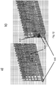
- Figs. 10a, 10b are photographs of a fully implemented retractable rail rack 550 as described above.
- the horizontal conveyance mechanism 520 can be raised and lowered by other means than a scissors mechanism, in the case implemented the horizontal conveyance mechanism 520 is lifted and lowered on chain 534 by gearbox and motors 532 atop the racks.
- the horizontal conveyance mechanism 520 may be lifted by a worm gear, rack and pinion, or other suitable, known mechanical means.
- Fig. 11 illustrates a conveyor 236 disposed laterally in front of additional rows of storage racks 550 that occupy the space previously needed for the bridge conveyors 232 ( Fig. 6 ) because the racks 550 are themselves able to raise or lower nodes to the working conveyor transport level 236.
- Figs. 12-13 schematically illustrate alternative aspects of item transport mechanisms.
- the vertically movable conveyance mechanism 520 rather than (or in addition to) horizontally moving items using a movable conveyor belt, itself can be moved on rails 610 affixed, e.g., to the deck ( Fig. 12b ).
- FIGs. 13a and 13b illustrate a different horizontal conveyance mechanism 520.
- Rails (or tracks) 610 are provided above the open space of the racks 510.
- a horizontal conveyance mechanism 520 is movably attached to the rails/tracks and can be vertically raised and lowered by, e.g., the illustrated scissors mechanism.
- the conveyance mechanism may comprise fingers or hanger members 633 that can engage one or more nodes 110 and slide them along the horizontal support members 511, which might be made of, or covered with, a low friction material (not shown).
- the system may include both a top-mounted, vertically movable conveyance mechanism as illustrated, e.g., in Fig. 13 and a bottom-mounted, vertically movable conveyance mechanism as illustrated, e.g., in Figs. 1-7 , 8-11 , or 12 .
- the one or more conveyance mechanisms that are movable in a vertical direction traversing the open space along the height H of the frame assembly may be disposed in vertical opposition, such that items in a lowest tier adjacent the bottom-mounted conveyance mechanism can be conveyed via the bottom-mounted conveyance mechanism and items in a highest tier adjacent the top-mounted conveyance mechanism can be conveyed via the top-mounted conveyance mechanism.
- Fig. 14a illustrates another ultra-dense storage apparatus and method embodiment.
- inclined planes with no machinery or moving parts are disposed in vertical spaced relation with curved end panels as shown.
- Rounded/rollable items can thus be transported by gravity alone. Because there are no moving parts or wearing surfaces, no service access needs to be provided, so the racks can abut each other side-by-side to provide very dense storage ( Fig. 14b ).
- a reference to "A and/or B", when used in conjunction with open-ended language such as “comprising” can refer, in one embodiment, to A only (optionally including elements other than B); in another embodiment, to B only (optionally including elements other than A); in yet another embodiment, to both A and B (optionally including other elements); etc.
- the phrase "at least one,” in reference to a list of one or more elements, should be understood to mean at least one element selected from any one or more of the elements in the list of elements, but not necessarily including at least one of each and every element specifically listed within the list of elements and not excluding any combinations of elements in the list of elements.
- This definition also allows that elements may optionally be present other than the elements specifically identified within the list of elements to which the phrase "at least one" refers, whether related or unrelated to those elements specifically identified.
- At least one of A and B can refer, in one embodiment, to at least one, optionally including more than one, A, with no B present (and optionally including elements other than B); in another embodiment, to at least one, optionally including more than one, B, with no A present (and optionally including elements other than A); in yet another embodiment, to at least one, optionally including more than one, A, and at least one, optionally including more than one, B (and optionally including other elements); etc.
Landscapes
- Engineering & Computer Science (AREA)
- Mechanical Engineering (AREA)
- Warehouses Or Storage Devices (AREA)
- Attitude Control For Articles On Conveyors (AREA)
- De-Stacking Of Articles (AREA)
- Intermediate Stations On Conveyors (AREA)
Claims (14)
- Artikelaufbewahrungs-, Ausgabe- und Empfangsvorrichtung, umfassend:eine Rahmenvorrichtung (510) mit einer Höhe, H, und einer Länge, L, umfassend mindestens einen Abschnitt davon mit zwei gegenüberliegenden Wandabschnitten, wobei jeder gegenüberliegende Seitenwandabschnitt eine Mehrzahl von vertikal beabstandeten Schienen umfasst, die an einer Innenfläche davon derart angeordnet sind, dass jede Schiene an einem jeweiligen Seitenwandabschnitt gegenüber einer entsprechenden Schiene an dem gegenüberliegenden Seitenwandabschnitt angeordnet ist, ferner wobei der mindestens eine Abschnitt einen offenen Zwischenraum aufweist, der sich zwischen der Mehrzahl von vertikal beabstandeten Schienen zwischen den beiden gegenüberliegenden Seitenwandabschnitten über die Höhe H und die Länge L vollständig erstreckt;einen Fördermechanismus oder mehrere Fördermechanismen, der bzw. die innerhalb des offenen Zwischenraums entlang von mindestens einem Abschnitt der Länge L operativ angeordnet ist bzw. sind, wobei der eine oder die mehreren Fördermechanismen in einer den offenen Zwischenraum entlang der Höhe L durchquerenden Vertikalrichtung beweglich ist; gekennzeichnet durcheine Mehrzahl von hängenden Armen (513), die an einem Bereich davon mit jeweils einem mit der Rahmenvorrichtung verbundenen Betätigungselement schwenkbar verbunden sind, wobei jede der Mehrzahl von Schienen (511) an einem distalen Bereich jedes der hängenden Arme befestigt sind, ferner wobei zumindest Abschnitte der Seitenwände Ausschnittbereiche aufweisen, so dass, bei Betätigung des Betätigungselements (516), die Schienen in die Ausschnittbereiche und aus diesen derart beweglich sind, dass die Schienen außerhalb bzw. innerhalb des offenen Zwischenraums angeordnet sind.
- Vorrichtung nach Anspruch 1, wobei die Mehrzahl von vertikal beabstandeten Schienen an der Rahmenvorrichtung derart befestigt sind, dass die Rahmenvorrichtung dadurch charakterisiert ist, dass sie keine beweglichen Teile aufweist.
- Vorrichtung nach Anspruch 1, wobei der eine oder die mehreren Fördermechanismen (520) angetriebene Förderbänder umfasst bzw. umfassen und mit einem Hebemechanismus oder mehreren Hebemechanismen gekoppelt ist bzw. sind, die dazu angepasst sind, den einen oder die mehreren Fördermechanismen (520) in der Vertikalrichtung in dem offenen Zwischenraum entlang der Höhe H der Rahmenvorrichtung gesteuert zu positionieren.
- Vorrichtung nach Anspruch 3, wobei der eine oder die mehreren Hebemechanismen unter dem einen oder den mehreren jeweiligen Fördermechanismen angeordnet ist bzw. sind.
- Vorrichtung nach Anspruch 1, ferner umfassend ein Gleis, das in dem offenen Raum angrenzend unterhalb von einem untersten entsprechenden Satz von Schienen der Rahmenvorrichtung entlang von zumindest einem Abschnitt der Länge L angeordnet ist, wobei der eine oder die mehreren Fördermechanismen (520) mit dem Gleis beweglich verbunden ist bzw. sind.
- Vorrichtung nach Anspruch 1, wobei die Rahmenvorrichtung ein Artikel-Eingangs-/Ausgangsende aufweist, ferner umfassend einen Brückenfördermechanismus (232) mit einem ersten Ende und einem zweiten Ende, ferner wobei eines des ersten Endes und des zweiten Endes des Brückenfördermechanismus mit einem führenden des einen oder der mehreren Fördermechanismen an dem Eingangs-/Ausgangsende der Rahmenvorrichtung derart wirkverbunden ist, dass, wenn sich der eine oder die mehreren Fördermechanismen in einer Vertikalrichtung bewegt bzw. bewegen, die den offenen Zwischenraum entlang der Höhe H durchquert, der Brückenfördermechanismus um das andere des ersten Endes und des zweiten Endes davon schwenkt, um einen kontinuierlichen Weg zwischen dem führenden des einen oder der mehreren Fördermechanismen an dem Eingangs-/Ausgangsende der Rahmenvorrichtung und dem Brückenfördermechanismus bereitzustellen.
- Vorrichtung nach Anspruch 1, ferner umfassend mindestens zwei der Rahmenvorrichtungen und jeweils einen oder mehrere Fördermechanismen (520), die unmittelbar seitlich angrenzend angeordnet sind.
- Vorrichtung nach Anspruch 7, wobei jede der Rahmenvorrichtungen ein Artikel-Eingangs-/Ausgangsende aufweist, ferner umfassend einen Brückenfördermechanismus (232) mit einem ersten Ende und einem zweiten Ende, ferner wobei eines des ersten Endes und des zweiten Endes des Brückenfördermechanismus mit einem führenden des einen oder der mehreren Fördermechanismen einer der mindestens zwei der Rahmenvorrichtungen an dem Eingangs-/Ausgangsende davon derart wirkverbunden ist, dass, wenn sich der eine oder die mehreren Fördermechanismen (520) in einer Vertikalrichtung bewegt bzw. bewegen, die den offenen Zwischenraum entlang der Höhe H durchquert, der Brückenfördermechanismus um das andere des ersten Endes und des zweiten Endes davon schwenkt, um einen kontinuierlichen Weg zwischen dem führenden des einen oder der mehreren Fördermechanismen (520) einer der mindestens zwei der Rahmenvorrichtungen an dem Eingangs-/Ausgangsende und dem Brückenfördermechanismus bereitzustellen, ferner wobei der Brückenfördermechanismus derart seitlich repositionierbar ist, dass er mit dem führenden des einen oder der mehreren Fördermechanismen der anderen der mindestens zwei der Rahmenvorrichtungen an dem Eingangs-/Ausgangsende davon wirkverbunden werden kann.
- Vorrichtung nach Anspruch 7, ferner umfassend eine Mehrzahl der unmittelbar seitlich angrenzenden mindestens zwei der Rahmenvorrichtungen und jeweils einen oder mehrere Fördermechanismen (520), die seitlich angrenzend angeordnet sind.
- Vorrichtung nach Anspruch 9, wobei jede der Rahmenvorrichtungen ein Artikel-Eingangs-/Ausgangsende aufweist, ferner umfassend eine Mehrzahl von Brückenfördermechanismen (232), die jeweils ein erstes Ende und ein zweites Ende aufweisen, ferner wobei eines des ersten Endes und des zweiten Endes von jedem der Brückenfördermechanismen mit einem führenden der Mehrzahl der unmittelbar seitlich angrenzenden mindestens zwei der Rahmenvorrichtungen und jeweils einem oder mehreren Fördermechanismen an den Eingangs-/Ausgangsenden davon derart wirkverbunden ist, dass, wenn sich der eine oder die mehreren Fördermechanismen in einer Vertikalrichtung bewegt bzw. bewegen, die den offenen Zwischenraum entlang der Höhe H durchquert, jeder der jeweiligen Brückenfördermechanismen um das andere des ersten Endes und des zweiten Endes davon schwenkt, um einen kontinuierlichen Weg zwischen den führenden des einen oder der mehreren Fördermechanismen einer der Mehrzahl der Rahmenvorrichtungen an den Eingangs-/Ausgangsenden und dem Brückenfördermechanismus bereitzustellen, ferner wobei der Brückenfördermechanismus seitlich repositionierbar ist.
- Vorrichtung nach Anspruch 9, wobei jede der Rahmenvorrichtungen (510) ein Artikel-Eingangs-/Ausgangsende aufweist, ferner umfassend einen unterschiedlichen Fördermechanismus, der angrenzend quer zu den Eingangs-/Ausgangsenden der Mehrzahl der unmittelbar seitlich angrenzenden mindestens zwei der Rahmenvorrichtungen angeordnet ist.
- Vorrichtung nach Anspruch 11, wobei der unterschiedliche Fördermechanismus (520) eine Mehrzahl von linear angrenzenden Fördermechanismen umfasst, die in einer horizontalen Ebene ausgerichtet sind.
- Vorrichtung nach Anspruch 1, ferner wobei nur ein einziger Fördermechanismus (520) in dem offenen Raum angeordnet ist, der durch den jeweils einen oder die mehreren Fördermechanismen durchquerbar ist.
- Vorrichtung nach Anspruch 1, ferner wobei der eine Fördermechanismus oder die mehreren Fördermechanismen (520), der bzw. die in einer Vertikalrichtung, die den offenen Raum entlang der Höhe H der Rahmenvorrichtung durchquert, beweglich ist bzw. sind, in vertikalem Gegensatz angeordnet ist bzw. sind.
Applications Claiming Priority (2)
| Application Number | Priority Date | Filing Date | Title |
|---|---|---|---|
| US201361774131P | 2013-03-07 | 2013-03-07 | |
| PCT/US2014/021180 WO2014138390A1 (en) | 2013-03-07 | 2014-03-06 | Item storage, dispensing, and receiving system, apparatus, methods, and applications |
Publications (3)
| Publication Number | Publication Date |
|---|---|
| EP2964548A1 EP2964548A1 (de) | 2016-01-13 |
| EP2964548A4 EP2964548A4 (de) | 2016-12-07 |
| EP2964548B1 true EP2964548B1 (de) | 2022-01-05 |
Family
ID=51491950
Family Applications (1)
| Application Number | Title | Priority Date | Filing Date |
|---|---|---|---|
| EP14760119.9A Not-in-force EP2964548B1 (de) | 2013-03-07 | 2014-03-06 | Artikelaufbewahrungs-, -ausgabe- und -empfangssystem, -vorrichtung, -verfahren und -anwendungen |
Country Status (9)
| Country | Link |
|---|---|
| US (1) | US9694974B2 (de) |
| EP (1) | EP2964548B1 (de) |
| CN (1) | CN105189312B (de) |
| AU (1) | AU2014225697B2 (de) |
| BR (1) | BR112015021580B1 (de) |
| CA (1) | CA2904263C (de) |
| MX (1) | MX362343B (de) |
| RU (1) | RU2657697C2 (de) |
| WO (1) | WO2014138390A1 (de) |
Families Citing this family (9)
| Publication number | Priority date | Publication date | Assignee | Title |
|---|---|---|---|---|
| US9459366B2 (en) | 2014-05-15 | 2016-10-04 | Seabed Geosolutions B.V. | Autonomous seismic node handling and storage system |
| EP3015400B1 (de) * | 2014-10-27 | 2017-08-09 | Intrion Nv | Aufbewahrungseinheit für große Transporttaschen |
| CN104401631B (zh) * | 2014-10-30 | 2016-05-18 | 重庆至信实业有限公司 | 后门加强板的容置架 |
| US10057133B2 (en) * | 2015-07-08 | 2018-08-21 | Fedex Corporate Services, Inc. | Systems, apparatus, and methods of enhanced monitoring for an event candidate associated with cycling power of an ID node within a wireless node network |
| US10018742B2 (en) * | 2016-03-31 | 2018-07-10 | Fairfield Industries, Inc. | Skid structure for underwater seismic exploration |
| US11609350B2 (en) * | 2018-10-12 | 2023-03-21 | Magseis Ff Llc | Modular seismic unit storage system with gantry robot and charging magazine |
| RU2732168C1 (ru) * | 2019-07-01 | 2020-09-14 | Алексей Васильевич Мирошниченко | Система формирования комплектов товаров или комплектующих |
| CN112158500B (zh) * | 2020-08-14 | 2022-05-03 | 四川宏华石油设备有限公司 | 一种管具存储移运系统及取管移运与存管移运方法 |
| CN112239060B (zh) * | 2020-11-17 | 2025-05-27 | 迈得医疗工业设备股份有限公司 | 医用供料装置及其设计方法 |
Family Cites Families (32)
| Publication number | Priority date | Publication date | Assignee | Title |
|---|---|---|---|---|
| USRE25117E (en) * | 1957-08-16 | 1962-01-30 | edwards | |
| FR1216307A (fr) * | 1957-09-19 | 1960-04-25 | Keller & Co C | Appareil pour le chargement des installations de séchage dans l'industrie céramique |
| US2982624A (en) * | 1958-03-31 | 1961-05-02 | Shell Oil Co | Acid concentration |
| IT1015457B (it) * | 1974-06-28 | 1977-05-10 | Pirelli | Metodo macchina e impianto per l immagazzinamento automatico di spezzoni di materiale elastomerico |
| IT1023645B (it) * | 1974-12-16 | 1978-05-30 | Spa | Apparecchiatura per l immagazzi manento di corpi f ani, in parti colare di piastpelle |
| SE415345B (sv) * | 1978-12-04 | 1980-09-29 | Siegfried Delius | Lageranleggning |
| NL186804C (nl) * | 1979-09-28 | 1991-03-01 | Capelleveen Bv Geb | Tussenopslag bakvormen. |
| SU1041436A1 (ru) * | 1982-04-21 | 1983-09-15 | Ленинградский Государственный Проектный Институт | Устройство дл загрузки и разгрузки стеллажей |
| JPS5943704A (ja) * | 1982-09-07 | 1984-03-10 | Tsubakimoto Chain Co | 物品取り出し装置 |
| SU1549857A1 (ru) * | 1986-03-14 | 1990-03-15 | Издательство "Известия Советов народных депутатов СССР" | Склад дл штучных грузов |
| DE3922964A1 (de) * | 1989-07-12 | 1991-01-17 | Keuro Maschinenbau Gmbh | Verfahren und vorrichtung zur aus- und einlagerung von stangen- oder plattenfoermiges material enthaltenden kassetten bei einem regallager |
| US5184738A (en) * | 1991-06-07 | 1993-02-09 | Frazier Industrial Company | Storage rack systems |
| US5211296A (en) * | 1991-10-01 | 1993-05-18 | Heygere Philippe N D | Device and process for the storage of products |
| DE4435993C2 (de) * | 1994-10-08 | 1998-04-16 | Riedhammer Gmbh Co Kg | Verwendung einer Vorrichtung zum Be- und Entladen eines Brenntischaufbaus mit Brenngut |
| FI105668B (fi) * | 1995-10-02 | 2000-09-29 | Cimcorp Oy | Poimintajärjestelmä |
| NO972004D0 (no) * | 1997-04-30 | 1997-04-30 | Hatteland Electronic As Jacob | Metode for organisering av vareflyt for en horisontalt lagdelt og dypstablet lagerbeholdning med uensartede komponenter, samt forflytningsutstyr for standariserte beholdere til formålet |
| JP2001072207A (ja) * | 1999-09-03 | 2001-03-21 | Nkk Corp | 物品の保管・仕分け装置およびそれを利用した物品の保管・仕分け方法 |
| US20030228208A1 (en) * | 2000-05-25 | 2003-12-11 | Grond Johann W. | Vertical conveyor and vertical conveyor system |
| US6776298B2 (en) * | 2001-04-03 | 2004-08-17 | Ridg-U-Rak, Inc. | Front beam and tension rod arrangement for push back rack storage system |
| CA2440916C (en) * | 2002-09-20 | 2011-05-24 | C.O.S.M.E. Inc. | Push-back pallet storage system |
| DE502005004267D1 (de) * | 2005-04-06 | 2008-07-10 | Josef Basic | Kistenstapellager |
| US7686560B2 (en) * | 2005-12-08 | 2010-03-30 | Conestoga Cold Storage | Rack, conveyor and shuttle automated pick system |
| JP5278724B2 (ja) * | 2007-07-26 | 2013-09-04 | 株式会社ダイフク | 物品収納設備 |
| CN201220833Y (zh) * | 2008-06-04 | 2009-04-15 | 济南兰剑物流科技有限责任公司 | 一种基于缓存原理和并行分拣机制的条烟快速分拣系统 |
| CN201254372Y (zh) * | 2008-07-25 | 2009-06-10 | 常熟泓淋电线电缆有限公司 | 线缆生产中所用仓储货架 |
| DE102009021467A1 (de) * | 2009-05-15 | 2010-11-18 | Ernst-Otto Esau | Lagersystem |
| CN201882525U (zh) * | 2010-11-24 | 2011-06-29 | 谢翠铭 | 无过道自动化立体仓库仓储装置 |
| US9919870B2 (en) * | 2011-07-01 | 2018-03-20 | Effimat Storage Technology Aps | Vertical lift storage system and a method of operating a lift |
| CN102633076A (zh) * | 2012-04-23 | 2012-08-15 | 金陵科技学院 | 一种带升降穿梭小车的立体仓库 |
| US9545150B2 (en) * | 2013-10-11 | 2017-01-17 | Steel King Industries, Inc. | Storage rack assembly with dual-rail truss-beam |
| US20150114919A1 (en) * | 2013-10-30 | 2015-04-30 | Wan Young Lee | Storage rack |
| PL2982624T3 (pl) * | 2014-08-04 | 2018-03-30 | Extor Gmbh | Urządzenie przytrzymujące i układ do magazynowania dla stosu pojemników |
-
2014
- 2014-03-06 MX MX2015011911A patent/MX362343B/es active IP Right Grant
- 2014-03-06 BR BR112015021580-7A patent/BR112015021580B1/pt not_active IP Right Cessation
- 2014-03-06 AU AU2014225697A patent/AU2014225697B2/en not_active Ceased
- 2014-03-06 WO PCT/US2014/021180 patent/WO2014138390A1/en not_active Ceased
- 2014-03-06 EP EP14760119.9A patent/EP2964548B1/de not_active Not-in-force
- 2014-03-06 US US14/772,859 patent/US9694974B2/en not_active Expired - Fee Related
- 2014-03-06 CA CA2904263A patent/CA2904263C/en active Active
- 2014-03-06 CN CN201480025334.2A patent/CN105189312B/zh not_active Expired - Fee Related
- 2014-03-06 RU RU2015140496A patent/RU2657697C2/ru active
Also Published As
| Publication number | Publication date |
|---|---|
| CN105189312A (zh) | 2015-12-23 |
| CA2904263A1 (en) | 2014-09-12 |
| RU2015140496A (ru) | 2017-04-12 |
| US9694974B2 (en) | 2017-07-04 |
| AU2014225697A1 (en) | 2015-09-24 |
| RU2657697C2 (ru) | 2018-06-14 |
| AU2014225697B2 (en) | 2017-01-19 |
| US20160009491A1 (en) | 2016-01-14 |
| EP2964548A1 (de) | 2016-01-13 |
| BR112015021580A2 (pt) | 2017-07-18 |
| BR112015021580B1 (pt) | 2021-01-26 |
| MX2015011911A (es) | 2016-04-15 |
| CA2904263C (en) | 2021-03-16 |
| CN105189312B (zh) | 2017-12-12 |
| MX362343B (es) | 2019-01-11 |
| WO2014138390A1 (en) | 2014-09-12 |
| EP2964548A4 (de) | 2016-12-07 |
Similar Documents
| Publication | Publication Date | Title |
|---|---|---|
| CA2904263C (en) | Item storage, dispensing, and receiving system, apparatus, methods, and applications | |
| US20210047113A1 (en) | Warehousing scalable storage structure | |
| BR112018067859B1 (pt) | Sistema composto de pelo menos um aparelho para armazenamento e recuperação e um sistema de transporte e transferência para armazenar e recuperar ou recolocar contêineres padrões em armazéns de prateleiras altas | |
| US6824345B2 (en) | Load-bearing frame for a shelf-stacking device | |
| EP3272679A1 (de) | Automatisch zentrierende ladungsunterstützung für shuttle-fahrzeuge mit veränderlicher aufnahmebreite | |
| US10589928B2 (en) | Storage and retrieval machine | |
| US20050095095A1 (en) | Support frame for a telescopic arm of a load-handling system and method of manipulating storage units | |
| US20130209202A1 (en) | Load bearing device for a rack retrieval system, rack retrieval system, and storage system | |
| CN107428480B (zh) | 用于将货柜仓库的货柜入仓及出仓的方法及货柜转运设施 | |
| CN105151613B (zh) | 一种升降堆垛式自动立库 | |
| CN104925444B (zh) | 一种移动堆垛式自动立库 | |
| RU2013142822A (ru) | Система хранения и комплектации с челноками | |
| US10647514B2 (en) | Transport robot with longitudinal conveyor | |
| GB2280178A (en) | Handling palettes in a warehouse | |
| EP2818432A1 (de) | System zum Lagern von Produktbehältern in einem Regallager mit Regalfahrzeugen | |
| CN212075342U (zh) | 交叉带分拣装置及交叉带分拣系统 | |
| CN204727025U (zh) | 一种移动堆垛式自动立库 | |
| CN204979960U (zh) | 一种升降堆垛式自动立库 | |
| CN110371890B (zh) | 一种运输装置 | |
| CN104960825A (zh) | 一种密集存储库 | |
| JP5781772B2 (ja) | 自動倉庫 | |
| CN211544772U (zh) | 一种物流仓储用智能分拣系统 | |
| CN208265093U (zh) | 一种立体仓库 | |
| CN204751203U (zh) | 一种密集存储库 | |
| EP3807056A1 (de) | Anlage zum bewegen von fahrzeugkarosserien |
Legal Events
| Date | Code | Title | Description |
|---|---|---|---|
| PUAI | Public reference made under article 153(3) epc to a published international application that has entered the european phase |
Free format text: ORIGINAL CODE: 0009012 |
|
| 17P | Request for examination filed |
Effective date: 20151007 |
|
| AK | Designated contracting states |
Kind code of ref document: A1 Designated state(s): AL AT BE BG CH CY CZ DE DK EE ES FI FR GB GR HR HU IE IS IT LI LT LU LV MC MK MT NL NO PL PT RO RS SE SI SK SM TR |
|
| AX | Request for extension of the european patent |
Extension state: BA ME |
|
| DAX | Request for extension of the european patent (deleted) | ||
| A4 | Supplementary search report drawn up and despatched |
Effective date: 20161109 |
|
| RIC1 | Information provided on ipc code assigned before grant |
Ipc: B65G 1/02 20060101AFI20161103BHEP Ipc: A47F 1/00 20060101ALI20161103BHEP |
|
| GRAP | Despatch of communication of intention to grant a patent |
Free format text: ORIGINAL CODE: EPIDOSNIGR1 |
|
| RIC1 | Information provided on ipc code assigned before grant |
Ipc: B65G 1/04 20060101ALI20210616BHEP Ipc: A47F 1/00 20060101ALI20210616BHEP Ipc: B65G 1/02 20060101AFI20210616BHEP |
|
| STAA | Information on the status of an ep patent application or granted ep patent |
Free format text: STATUS: GRANT OF PATENT IS INTENDED |
|
| INTG | Intention to grant announced |
Effective date: 20210722 |
|
| GRAS | Grant fee paid |
Free format text: ORIGINAL CODE: EPIDOSNIGR3 |
|
| GRAA | (expected) grant |
Free format text: ORIGINAL CODE: 0009210 |
|
| STAA | Information on the status of an ep patent application or granted ep patent |
Free format text: STATUS: THE PATENT HAS BEEN GRANTED |
|
| RAP1 | Party data changed (applicant data changed or rights of an application transferred) |
Owner name: MAGSEIS FF LLC |
|
| AK | Designated contracting states |
Kind code of ref document: B1 Designated state(s): AL AT BE BG CH CY CZ DE DK EE ES FI FR GB GR HR HU IE IS IT LI LT LU LV MC MK MT NL NO PL PT RO RS SE SI SK SM TR |
|
| REG | Reference to a national code |
Ref country code: GB Ref legal event code: FG4D |
|
| REG | Reference to a national code |
Ref country code: CH Ref legal event code: EP |
|
| REG | Reference to a national code |
Ref country code: AT Ref legal event code: REF Ref document number: 1460359 Country of ref document: AT Kind code of ref document: T Effective date: 20220115 |
|
| REG | Reference to a national code |
Ref country code: IE Ref legal event code: FG4D |
|
| REG | Reference to a national code |
Ref country code: DE Ref legal event code: R096 Ref document number: 602014082036 Country of ref document: DE |
|
| REG | Reference to a national code |
Ref country code: LT Ref legal event code: MG9D |
|
| REG | Reference to a national code |
Ref country code: NL Ref legal event code: MP Effective date: 20220105 |
|
| PGFP | Annual fee paid to national office [announced via postgrant information from national office to epo] |
Ref country code: FR Payment date: 20220221 Year of fee payment: 9 |
|
| REG | Reference to a national code |
Ref country code: NO Ref legal event code: T2 Effective date: 20220105 |
|
| REG | Reference to a national code |
Ref country code: AT Ref legal event code: MK05 Ref document number: 1460359 Country of ref document: AT Kind code of ref document: T Effective date: 20220105 |
|
| PG25 | Lapsed in a contracting state [announced via postgrant information from national office to epo] |
Ref country code: NL Free format text: LAPSE BECAUSE OF FAILURE TO SUBMIT A TRANSLATION OF THE DESCRIPTION OR TO PAY THE FEE WITHIN THE PRESCRIBED TIME-LIMIT Effective date: 20220105 |
|
| PG25 | Lapsed in a contracting state [announced via postgrant information from national office to epo] |
Ref country code: SE Free format text: LAPSE BECAUSE OF FAILURE TO SUBMIT A TRANSLATION OF THE DESCRIPTION OR TO PAY THE FEE WITHIN THE PRESCRIBED TIME-LIMIT Effective date: 20220105 Ref country code: RS Free format text: LAPSE BECAUSE OF FAILURE TO SUBMIT A TRANSLATION OF THE DESCRIPTION OR TO PAY THE FEE WITHIN THE PRESCRIBED TIME-LIMIT Effective date: 20220105 Ref country code: PT Free format text: LAPSE BECAUSE OF FAILURE TO SUBMIT A TRANSLATION OF THE DESCRIPTION OR TO PAY THE FEE WITHIN THE PRESCRIBED TIME-LIMIT Effective date: 20220505 Ref country code: LT Free format text: LAPSE BECAUSE OF FAILURE TO SUBMIT A TRANSLATION OF THE DESCRIPTION OR TO PAY THE FEE WITHIN THE PRESCRIBED TIME-LIMIT Effective date: 20220105 Ref country code: HR Free format text: LAPSE BECAUSE OF FAILURE TO SUBMIT A TRANSLATION OF THE DESCRIPTION OR TO PAY THE FEE WITHIN THE PRESCRIBED TIME-LIMIT Effective date: 20220105 Ref country code: ES Free format text: LAPSE BECAUSE OF FAILURE TO SUBMIT A TRANSLATION OF THE DESCRIPTION OR TO PAY THE FEE WITHIN THE PRESCRIBED TIME-LIMIT Effective date: 20220105 Ref country code: BG Free format text: LAPSE BECAUSE OF FAILURE TO SUBMIT A TRANSLATION OF THE DESCRIPTION OR TO PAY THE FEE WITHIN THE PRESCRIBED TIME-LIMIT Effective date: 20220405 |
|
| PG25 | Lapsed in a contracting state [announced via postgrant information from national office to epo] |
Ref country code: PL Free format text: LAPSE BECAUSE OF FAILURE TO SUBMIT A TRANSLATION OF THE DESCRIPTION OR TO PAY THE FEE WITHIN THE PRESCRIBED TIME-LIMIT Effective date: 20220105 Ref country code: LV Free format text: LAPSE BECAUSE OF FAILURE TO SUBMIT A TRANSLATION OF THE DESCRIPTION OR TO PAY THE FEE WITHIN THE PRESCRIBED TIME-LIMIT Effective date: 20220105 Ref country code: GR Free format text: LAPSE BECAUSE OF FAILURE TO SUBMIT A TRANSLATION OF THE DESCRIPTION OR TO PAY THE FEE WITHIN THE PRESCRIBED TIME-LIMIT Effective date: 20220406 Ref country code: FI Free format text: LAPSE BECAUSE OF FAILURE TO SUBMIT A TRANSLATION OF THE DESCRIPTION OR TO PAY THE FEE WITHIN THE PRESCRIBED TIME-LIMIT Effective date: 20220105 Ref country code: AT Free format text: LAPSE BECAUSE OF FAILURE TO SUBMIT A TRANSLATION OF THE DESCRIPTION OR TO PAY THE FEE WITHIN THE PRESCRIBED TIME-LIMIT Effective date: 20220105 |
|
| PG25 | Lapsed in a contracting state [announced via postgrant information from national office to epo] |
Ref country code: IS Free format text: LAPSE BECAUSE OF FAILURE TO SUBMIT A TRANSLATION OF THE DESCRIPTION OR TO PAY THE FEE WITHIN THE PRESCRIBED TIME-LIMIT Effective date: 20220505 |
|
| REG | Reference to a national code |
Ref country code: DE Ref legal event code: R119 Ref document number: 602014082036 Country of ref document: DE |
|
| PG25 | Lapsed in a contracting state [announced via postgrant information from national office to epo] |
Ref country code: SM Free format text: LAPSE BECAUSE OF FAILURE TO SUBMIT A TRANSLATION OF THE DESCRIPTION OR TO PAY THE FEE WITHIN THE PRESCRIBED TIME-LIMIT Effective date: 20220105 Ref country code: SK Free format text: LAPSE BECAUSE OF FAILURE TO SUBMIT A TRANSLATION OF THE DESCRIPTION OR TO PAY THE FEE WITHIN THE PRESCRIBED TIME-LIMIT Effective date: 20220105 Ref country code: RO Free format text: LAPSE BECAUSE OF FAILURE TO SUBMIT A TRANSLATION OF THE DESCRIPTION OR TO PAY THE FEE WITHIN THE PRESCRIBED TIME-LIMIT Effective date: 20220105 Ref country code: MC Free format text: LAPSE BECAUSE OF FAILURE TO SUBMIT A TRANSLATION OF THE DESCRIPTION OR TO PAY THE FEE WITHIN THE PRESCRIBED TIME-LIMIT Effective date: 20220105 Ref country code: EE Free format text: LAPSE BECAUSE OF FAILURE TO SUBMIT A TRANSLATION OF THE DESCRIPTION OR TO PAY THE FEE WITHIN THE PRESCRIBED TIME-LIMIT Effective date: 20220105 Ref country code: DK Free format text: LAPSE BECAUSE OF FAILURE TO SUBMIT A TRANSLATION OF THE DESCRIPTION OR TO PAY THE FEE WITHIN THE PRESCRIBED TIME-LIMIT Effective date: 20220105 Ref country code: CZ Free format text: LAPSE BECAUSE OF FAILURE TO SUBMIT A TRANSLATION OF THE DESCRIPTION OR TO PAY THE FEE WITHIN THE PRESCRIBED TIME-LIMIT Effective date: 20220105 |
|
| REG | Reference to a national code |
Ref country code: CH Ref legal event code: PL |
|
| PLBE | No opposition filed within time limit |
Free format text: ORIGINAL CODE: 0009261 |
|
| STAA | Information on the status of an ep patent application or granted ep patent |
Free format text: STATUS: NO OPPOSITION FILED WITHIN TIME LIMIT |
|
| PG25 | Lapsed in a contracting state [announced via postgrant information from national office to epo] |
Ref country code: AL Free format text: LAPSE BECAUSE OF FAILURE TO SUBMIT A TRANSLATION OF THE DESCRIPTION OR TO PAY THE FEE WITHIN THE PRESCRIBED TIME-LIMIT Effective date: 20220105 |
|
| REG | Reference to a national code |
Ref country code: BE Ref legal event code: MM Effective date: 20220331 |
|
| 26N | No opposition filed |
Effective date: 20221006 |
|
| PG25 | Lapsed in a contracting state [announced via postgrant information from national office to epo] |
Ref country code: LU Free format text: LAPSE BECAUSE OF NON-PAYMENT OF DUE FEES Effective date: 20220306 Ref country code: LI Free format text: LAPSE BECAUSE OF NON-PAYMENT OF DUE FEES Effective date: 20220331 Ref country code: IE Free format text: LAPSE BECAUSE OF NON-PAYMENT OF DUE FEES Effective date: 20220306 Ref country code: DE Free format text: LAPSE BECAUSE OF NON-PAYMENT OF DUE FEES Effective date: 20221001 Ref country code: CH Free format text: LAPSE BECAUSE OF NON-PAYMENT OF DUE FEES Effective date: 20220331 |
|
| PG25 | Lapsed in a contracting state [announced via postgrant information from national office to epo] |
Ref country code: SI Free format text: LAPSE BECAUSE OF FAILURE TO SUBMIT A TRANSLATION OF THE DESCRIPTION OR TO PAY THE FEE WITHIN THE PRESCRIBED TIME-LIMIT Effective date: 20220105 Ref country code: BE Free format text: LAPSE BECAUSE OF NON-PAYMENT OF DUE FEES Effective date: 20220331 |
|
| PGFP | Annual fee paid to national office [announced via postgrant information from national office to epo] |
Ref country code: NO Payment date: 20230203 Year of fee payment: 10 |
|
| PGFP | Annual fee paid to national office [announced via postgrant information from national office to epo] |
Ref country code: GB Payment date: 20230203 Year of fee payment: 10 |
|
| PG25 | Lapsed in a contracting state [announced via postgrant information from national office to epo] |
Ref country code: IT Free format text: LAPSE BECAUSE OF FAILURE TO SUBMIT A TRANSLATION OF THE DESCRIPTION OR TO PAY THE FEE WITHIN THE PRESCRIBED TIME-LIMIT Effective date: 20220105 |
|
| PG25 | Lapsed in a contracting state [announced via postgrant information from national office to epo] |
Ref country code: FR Free format text: LAPSE BECAUSE OF NON-PAYMENT OF DUE FEES Effective date: 20230331 |
|
| PG25 | Lapsed in a contracting state [announced via postgrant information from national office to epo] |
Ref country code: HU Free format text: LAPSE BECAUSE OF FAILURE TO SUBMIT A TRANSLATION OF THE DESCRIPTION OR TO PAY THE FEE WITHIN THE PRESCRIBED TIME-LIMIT; INVALID AB INITIO Effective date: 20140306 |
|
| PG25 | Lapsed in a contracting state [announced via postgrant information from national office to epo] |
Ref country code: MK Free format text: LAPSE BECAUSE OF FAILURE TO SUBMIT A TRANSLATION OF THE DESCRIPTION OR TO PAY THE FEE WITHIN THE PRESCRIBED TIME-LIMIT Effective date: 20220105 Ref country code: CY Free format text: LAPSE BECAUSE OF FAILURE TO SUBMIT A TRANSLATION OF THE DESCRIPTION OR TO PAY THE FEE WITHIN THE PRESCRIBED TIME-LIMIT Effective date: 20220105 |
|
| PG25 | Lapsed in a contracting state [announced via postgrant information from national office to epo] |
Ref country code: TR Free format text: LAPSE BECAUSE OF FAILURE TO SUBMIT A TRANSLATION OF THE DESCRIPTION OR TO PAY THE FEE WITHIN THE PRESCRIBED TIME-LIMIT Effective date: 20220105 |
|
| PG25 | Lapsed in a contracting state [announced via postgrant information from national office to epo] |
Ref country code: MT Free format text: LAPSE BECAUSE OF FAILURE TO SUBMIT A TRANSLATION OF THE DESCRIPTION OR TO PAY THE FEE WITHIN THE PRESCRIBED TIME-LIMIT Effective date: 20220105 |
|
| GBPC | Gb: european patent ceased through non-payment of renewal fee |
Effective date: 20240306 |
|
| PG25 | Lapsed in a contracting state [announced via postgrant information from national office to epo] |
Ref country code: NO Free format text: LAPSE BECAUSE OF NON-PAYMENT OF DUE FEES Effective date: 20240331 |
|
| PG25 | Lapsed in a contracting state [announced via postgrant information from national office to epo] |
Ref country code: GB Free format text: LAPSE BECAUSE OF NON-PAYMENT OF DUE FEES Effective date: 20240306 |
|
| PG25 | Lapsed in a contracting state [announced via postgrant information from national office to epo] |
Ref country code: NO Free format text: LAPSE BECAUSE OF NON-PAYMENT OF DUE FEES Effective date: 20240331 Ref country code: GB Free format text: LAPSE BECAUSE OF NON-PAYMENT OF DUE FEES Effective date: 20240306 |