EP2963751A1 - Direct-current circuit breaker and implementation method therefor - Google Patents
Direct-current circuit breaker and implementation method therefor Download PDFInfo
- Publication number
- EP2963751A1 EP2963751A1 EP13876671.2A EP13876671A EP2963751A1 EP 2963751 A1 EP2963751 A1 EP 2963751A1 EP 13876671 A EP13876671 A EP 13876671A EP 2963751 A1 EP2963751 A1 EP 2963751A1
- Authority
- EP
- European Patent Office
- Prior art keywords
- current
- circuit
- commutation
- unit
- converter
- Prior art date
- Legal status (The legal status is an assumption and is not a legal conclusion. Google has not performed a legal analysis and makes no representation as to the accuracy of the status listed.)
- Granted
Links
Images


Classifications
-
- H—ELECTRICITY
- H02—GENERATION; CONVERSION OR DISTRIBUTION OF ELECTRIC POWER
- H02H—EMERGENCY PROTECTIVE CIRCUIT ARRANGEMENTS
- H02H3/00—Emergency protective circuit arrangements for automatic disconnection directly responsive to an undesired change from normal electric working condition with or without subsequent reconnection ; integrated protection
- H02H3/38—Emergency protective circuit arrangements for automatic disconnection directly responsive to an undesired change from normal electric working condition with or without subsequent reconnection ; integrated protection responsive to both voltage and current; responsive to phase angle between voltage and current
-
- H—ELECTRICITY
- H01—ELECTRIC ELEMENTS
- H01H—ELECTRIC SWITCHES; RELAYS; SELECTORS; EMERGENCY PROTECTIVE DEVICES
- H01H33/00—High-tension or heavy-current switches with arc-extinguishing or arc-preventing means
- H01H33/02—Details
- H01H33/59—Circuit arrangements not adapted to a particular application of the switch and not otherwise provided for, e.g. for ensuring operation of the switch at a predetermined point in the AC cycle
- H01H33/596—Circuit arrangements not adapted to a particular application of the switch and not otherwise provided for, e.g. for ensuring operation of the switch at a predetermined point in the AC cycle for interrupting DC
-
- H—ELECTRICITY
- H02—GENERATION; CONVERSION OR DISTRIBUTION OF ELECTRIC POWER
- H02H—EMERGENCY PROTECTIVE CIRCUIT ARRANGEMENTS
- H02H9/00—Emergency protective circuit arrangements for limiting excess current or voltage without disconnection
- H02H9/02—Emergency protective circuit arrangements for limiting excess current or voltage without disconnection responsive to excess current
-
- H—ELECTRICITY
- H01—ELECTRIC ELEMENTS
- H01H—ELECTRIC SWITCHES; RELAYS; SELECTORS; EMERGENCY PROTECTIVE DEVICES
- H01H83/00—Protective switches, e.g. circuit-breaking switches, or protective relays operated by abnormal electrical conditions otherwise than solely by excess current
- H01H83/20—Protective switches, e.g. circuit-breaking switches, or protective relays operated by abnormal electrical conditions otherwise than solely by excess current operated by excess current as well as by some other abnormal electrical condition
-
- H—ELECTRICITY
- H01—ELECTRIC ELEMENTS
- H01H—ELECTRIC SWITCHES; RELAYS; SELECTORS; EMERGENCY PROTECTIVE DEVICES
- H01H9/00—Details of switching devices, not covered by groups H01H1/00 - H01H7/00
- H01H9/54—Circuit arrangements not adapted to a particular application of the switching device and for which no provision exists elsewhere
- H01H9/541—Contacts shunted by semiconductor devices
- H01H9/542—Contacts shunted by static switch means
-
- H—ELECTRICITY
- H02—GENERATION; CONVERSION OR DISTRIBUTION OF ELECTRIC POWER
- H02H—EMERGENCY PROTECTIVE CIRCUIT ARRANGEMENTS
- H02H3/00—Emergency protective circuit arrangements for automatic disconnection directly responsive to an undesired change from normal electric working condition with or without subsequent reconnection ; integrated protection
- H02H3/08—Emergency protective circuit arrangements for automatic disconnection directly responsive to an undesired change from normal electric working condition with or without subsequent reconnection ; integrated protection responsive to excess current
-
- H—ELECTRICITY
- H02—GENERATION; CONVERSION OR DISTRIBUTION OF ELECTRIC POWER
- H02H—EMERGENCY PROTECTIVE CIRCUIT ARRANGEMENTS
- H02H7/00—Emergency protective circuit arrangements specially adapted for specific types of electric machines or apparatus or for sectionalised protection of cable or line systems, and effecting automatic switching in the event of an undesired change from normal working conditions
- H02H7/26—Sectionalised protection of cable or line systems, e.g. for disconnecting a section on which a short-circuit, earth fault, or arc discharge has occured
- H02H7/268—Sectionalised protection of cable or line systems, e.g. for disconnecting a section on which a short-circuit, earth fault, or arc discharge has occured for DC systems
-
- H—ELECTRICITY
- H02—GENERATION; CONVERSION OR DISTRIBUTION OF ELECTRIC POWER
- H02J—ELECTRIC POWER NETWORKS; CIRCUIT ARRANGEMENTS OR SYSTEMS FOR SUPPLYING OR DISTRIBUTING ELECTRIC POWER; SYSTEMS FOR STORING ELECTRIC ENERGY
- H02J1/00—Circuit arrangements for DC mains or DC distribution networks
Definitions
- the invention relates to a power electronic technology, more particularly, to a direct current circuit breaker and its implementation process.
- the quick direct current circuit breaker becomes the key device to ensure the system running security, stability and reliability.
- the alternating current has two natural zero-crossing points in a period, the alternating current circuit breaker just uses the current natural zero-crossing point to cut off the current, meanwhile the direct current has no natural zero-crossing point, therefor, the cut off of the direct current is far more different than the cut off of the alternating current.
- the present invention provides a direct current circuit breaker and its implementation process, which realizes the effect of cutting out the direct current by turn-off power electronic devices, it has no arc cutting and fast speed.
- said cutout unit and commutation unit all include the half/full bridge structure converter;
- the number of converters in the cutout unit is greater than it in the commutation unit, said commutation unit has a smaller on-resistance compared to said cutout unit.
- said full bridge structure converter includes the capacitor and H bridge structure power semiconductor switch module;
- Said H bridge structure power semiconductor switch module includes four power semiconductor switch modules; Wherein each two in series together and constitute a branch, two branches parallel, and extract the intermediate point of the two branches as the input or output end;
- the number of said capacitor is at least one, and it connects with the power semiconductor switch module branch after a series.
- said H bridge structure power semiconductor switch module includes four diodes and at least one power semiconductor switch; Wherein each two diodes are in series to consist a branch, two branches parallel, and the intermediate point of the two branches is extracted as the input end and output end; Wherein the power semiconductor switch is in parallel with the capacitor and in parallel with said branch made up by the diodes.
- said half bridge structure converter includes two power semiconductor switch modules and at least one capacitor; Said two power semiconductor switch modules, after in series together, are in parallel with the capacitor; The intermediate point between one end of the capacitor and power semiconductor switch module connected in series is as the input or output end.
- said power semiconductor switch module includes power semiconductor switch parallel opposite and fly back diode.
- said energy absorption circuit includes lightning arrester and slide rheostat.
- a limit current device consists of said direct current breaker, of which the improvement is that it comprises at least said two current breakers connected in series, a branch in series made by said direct current breaker is connected with a current path of transmission or distribution line.
- Said current limiting device suits for handling a certain number of said direct current circuit breaker when the current beyond the current limit in the current path so that it makes the current of said mechanical switch and commutation unit of said at least two direct current circuit breakers reverse to the energy absorption circuit.
- the specific number is determined by the current limit level, in general, the principle to select the number is: making the current drop to or below the current limit and keeping in the reservation current value at least at a certain time period.
- a limit current device comprises at least one set parallel interrupt unit and energy absorption circuit, and mechanical switch and cutout unit in series; Each set parallel interrupt unit and the energy absorption circuit is in series;
- An application method of the direct current circuit breaker improved is that, said method includes the following steps:
- control circuit sends the signal to turn off the converter of said commutation unit
- the extreme value of the first current is greater than or equal to the rated current of the circuit connect to the convertor station.
- step C turn off said mechanical switch after the first period time form locking said commutation unit.
- step C controls circuit judge current when the current switches to cutout circuit form commutation circuit, the control circuit turns off said mechanical switch.
- the application method used for the first current limiting device is that, when said current in the current path exceeds the limit determined by the applied line, the first specific number of said at least two devices is handled, and the corresponding cutout unit converter form this is locked to make the current reverse to said corresponding energy absorption circuit.
- the application method for using the second current limiting device is that, when the current exceeds the current limit in said current path, the commutation unit converter is locked, the mechanical switch is cut off, and then the first specific number said cutout unit converters is locked, thus to make the current reverse , through said high speed mechanical switch and said commutation unit converter, to the first specific number cutout unit converters, and then converse to the corresponding energy absorption circuit.
- a breaker is illustrated by the present embodiment, its electrical structure shown as figure 1 , including the cutout circuit, the commutation circuit and the energy absorption circuit connected in parallel.
- the commutation circuit is used for switching the external current into cutout circuit, including commutation inductance, commutation unit and mechanical switch connected in series, turn-on the bidirectional current;
- the commutation unit only enduring the on-state voltage drop when the cutout switch turns on;
- the high speed switch cuts off, it endures the voltage of the whole breaker.
- the number of the mechanical switch is at least one, so that it can endure the higher voltage.
- the cutout circuit is in charge of quickly cutting off the direct current in the path after the high speed switch cutting off, the cut-off, it can cut off the bidirectional current, wherein including cutout inductance and cutout unit connected in series.
- the commutation inductance in the commutation circuit and the cutout inductance in the cutout circuit used are the normal inductance, such as air-core inductance with dozens of microhenries.
- the full or half bridge structure converter is included, but number of the cutout unit is greater than it of the commutation unit, so that commutation unit has a smaller on-resistance compared to cutout unit.
- the full bridge structure converter includes H bridge structure power semiconductor switch module and the capacitor, as shown in figure 2 ,number of the capacitor is at least one, and it connects with the power semiconductor switch module branch after a series, wherein:
- Half bridge structure converter includes the capacitor and two power semiconductor module, as shown in figure 4 ; Said two power semiconductor module after in series are in parallel with the capacitor, and extract the intermediate point between one end of the capacitor and the power semiconductor module as the input end and output end.
- Two half bridge structure converters, commutation inductance and mechanical switch are in series and constitute the commutation circuit.
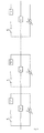
- the breaker realized by the half bridge structure converter is shown as figure 7 .
- the power semiconductor switch module in the present embodiment includes IGBT and diode parallel opposite.
- the energy absorption circuit after cutting off the circuit and the direct current can absorb the energy stored by the inductance of the HVDC system, including lightning arrester and slide rheostat. While realizing by the slide rheostat, where the voltage in the system is higher, the value of resistance of the slide rheostat is less, where the voltage in the system is smaller, the value of resistance of the slide rheostat is larger.
- control circuit shown as figure 8 .
- the control circuit controls the turning-on and cutting off of the commutation circuit, the cutout circuit and the mechanical switch, being used to for controlling the circuit bring in and quite. It could include the processor, DSP or FPGA and others.
- the turn off signal of the commutation unit converter is still received or received again, firstly the commutation unit converter is turned off, after that, turn off the high speed mechanical switch is turned off, and after that since receiving the turn off signal of said cutout unit converter, and then the cutout unit converter is turned off.
- the first specific number of said at least two devices is handled, to make the corresponding cutout unit converter form this lock, and can make the current reverse to said corresponding energy absorption circuit, shown as figure 9 .
- the commutation unit converter is locked, the high speed mechanical switch is cut off, and then the first specific number said cutout unit converters is locked, thus to make the current through said high speed mechanical switch and said commutation unit converter reverse to the first specific number cutout unit converters, and then to make it converse to the corresponding energy absorption circuit, shown as figure 10 .
- said first specific number is determined.
- the first current limiting arrangement proposed by the present embodiment is shown as figure 9 , that it is in series multiple direct current breaker. Said current limiting arrangement is suit for handling a certain number of said direct current circuit breaker when the current beyond the current limit in the current path, and it make the current of said mechanical switch and commutation unit of said at least two direct current circuit breakers reverse to the energy absorption circuit.
- the second current limiting arrangement proposed by the present embodiment is shown as figure 10 , correspondingly its structure is changed, including at least one set parallel commutation unit and energy absorption circuit, and mechanical switch and cutout unit in series; each set parallel commutation unit is in series energy absorption circuit;
- said mechanical switch, said commutation unit and the parallel cutout unit and energy absorption circuit are handled to make the current flowed through the mechanical switch and the commutation unit reverse to the cutout unit and the energy absorption circuit in series.
- the embodiment uses power semiconductor switch module to realize the function of commutation and cutout, achieve the effect of cost savings.
Landscapes
- Engineering & Computer Science (AREA)
- Power Engineering (AREA)
- Driving Mechanisms And Operating Circuits Of Arc-Extinguishing High-Tension Switches (AREA)
- Inverter Devices (AREA)
- Emergency Protection Circuit Devices (AREA)
Abstract
Description
- The invention relates to a power electronic technology, more particularly, to a direct current circuit breaker and its implementation process.
- As the technology based on the multi terminal flexible direct current of the VSC and DC power grid comes to be used, the quick direct current circuit breaker becomes the key device to ensure the system running security, stability and reliability. In the exchange system, the alternating current has two natural zero-crossing points in a period, the alternating current circuit breaker just uses the current natural zero-crossing point to cut off the current, meanwhile the direct current has no natural zero-crossing point, therefor, the cut off of the direct current is far more different than the cut off of the alternating current.
- Generally speaking, there are two method to cut off the direct current, one is based on the general alternating mechanical switch, superimposing increasing oscillation current on direct current of the arcing gap by adding auxiliary circuit, cutting off the circuit by the current passes through zero, and the mechanical switch breaker is manufactured by this principle, it cannot meet the demands of the multi terminal flexible direct current transmission system on the breaking time; Another is that a high power cut-off power electronic device is used to break the direct current directly, although the solid-state breaker manufactured by this principle can meet the demands of the multi terminal flexible direct current transmission system on the breaking time, it has an oversize loss and poor economic nature when it is turned on normally.
- Aiming at the disadvantages and limitations of existing technology, the present invention provides a direct current circuit breaker and its implementation process, which realizes the effect of cutting out the direct current by turn-off power electronic devices, it has no arc cutting and fast speed.
- The present invention is realized by the technical scheme below:
- A direct current circuit breaker, said breaker includes the cutout circuit, the commutation circuit and the energy absorption circuit connected in parallel, what is improved is: Said cutout circuit includes cutout inductance and cutout unit connected in series; Said commutation circuit includes commutation inductance, commutation unit and mechanical switch connected in series.
- Wherein, said cutout unit and commutation unit all include the half/full bridge structure converter;
The number of converters in the cutout unit is greater than it in the commutation unit, said commutation unit has a smaller on-resistance compared to said cutout unit. - Wherein, said full bridge structure converter includes the capacitor and H bridge structure power semiconductor switch module; Said H bridge structure power semiconductor switch module includes four power semiconductor switch modules; Wherein each two in series together and constitute a branch, two branches parallel, and extract the intermediate point of the two branches as the input or output end; The number of said capacitor is at least one, and it connects with the power semiconductor switch module branch after a series.
- Wherein, said H bridge structure power semiconductor switch module includes four diodes and at least one power semiconductor switch; Wherein each two diodes are in series to consist a branch, two branches parallel, and the intermediate point of the two branches is extracted as the input end and output end; Wherein the power semiconductor switch is in parallel with the capacitor and in parallel with said branch made up by the diodes. Wherein, said half bridge structure converter includes two power semiconductor switch modules and at least one capacitor; Said two power semiconductor switch modules, after in series together, are in parallel with the capacitor; The intermediate point between one end of the capacitor and power semiconductor switch module connected in series is as the input or output end. Wherein, said power semiconductor switch module includes power semiconductor switch parallel opposite and fly back diode.
- Wherein, the number of said mechanical switch is at least one. Wherein, said energy absorption circuit includes lightning arrester and slide rheostat.
- A limit current device consists of said direct current breaker, of which the improvement is that it comprises at least said two current breakers connected in series, a branch in series made by said direct current breaker is connected with a current path of transmission or distribution line. Said current limiting device suits for handling a certain number of said direct current circuit breaker when the current beyond the current limit in the current path so that it makes the current of said mechanical switch and commutation unit of said at least two direct current circuit breakers reverse to the energy absorption circuit. Wherein, the specific number is determined by the current limit level, in general, the principle to select the number is: making the current drop to or below the current limit and keeping in the reservation current value at least at a certain time period.
- A limit current device comprises at least one set parallel interrupt unit and energy absorption circuit, and mechanical switch and cutout unit in series; Each set parallel interrupt unit and the energy absorption circuit is in series;
- When the current flowing beyond the current limit in the current path, handling said mechanical switch, and the parallel cutout unit and energy absorption circuit, and it make the current flowed through the mechanical switch and the commutation unit reverse to the parallel cutout unit and the energy absorption circuit.
- An application method of the direct current circuit breaker improved is that, said method includes the following steps:
- A The circuit controls the converter of the commutation unit is turned on under control, the mechanical switch is closed;
- B The current value of every path is tested by the control circuit, when it needs to break the direct current in the circuit, the control circuit triggers the converter of the cutout unit, if the signal from lock converter of the commutation unit is received, then the converter of the commutation unit is locked; The capacitors of the commutation inductance and commutation unit form the oscillation, so that it moves the current into the cutout circuit;
- C Turning off said mechanical switch, and making it have enough fracture length;
- D If the signal from the lock converter of the cutout unit is received, then the converter of the cutout unit is locked, to switch the current to the cutout unit capacitor, the current in the circuit charges the capacitor in the cutout unit, the capacitor voltage starts to rise;
- E When the capacitor voltage rises to the energy absorption circuit action voltage, and switches the current into the energy absorption circuit.
- If the current value of every path tested in step B exceeds the first current limit, the control circuit sends the signal to turn off the converter of said commutation unit;
- The extreme value of the first current is greater than or equal to the rated current of the circuit connect to the convertor station.
- Wherein, step C turn off said mechanical switch after the first period time form locking said commutation unit.
- Wherein, step C controls circuit judge current when the current switches to cutout circuit form commutation circuit, the control circuit turns off said mechanical switch.
- Wherein, under the condition of said commutation unit converter locking or not receiving the cutout unit converter locking signal on the second period time form the time turning off the mechanical switch.
- Wherein, after cutting off the high speed mechanical switch and unlocking said commutation unit converter, it still receiving or receiving again the turn off signal of the commutation unit converter, after that, turn off the high speed mechanical switch, and after that since receiving the turn off signal of said cutout unit converter, then it turns off the cutout unit converter.
- The application method used for the first current limiting device is that, when said current in the current path exceeds the limit determined by the applied line, the first specific number of said at least two devices is handled, and the corresponding cutout unit converter form this is locked to make the current reverse to said corresponding energy absorption circuit.
- The application method for using the second current limiting device is that, when the current exceeds the current limit in said current path, the commutation unit converter is locked, the mechanical switch is cut off, and then the first specific number said cutout unit converters is locked, thus to make the current reverse , through said high speed mechanical switch and said commutation unit converter, to the first specific number cutout unit converters, and then converse to the corresponding energy absorption circuit.
- Wherein, based on the current limit level said first specific number is determined.
- Wherein, monitoring the heat of the energy absorption circuit which is corresponding to the locking cutout unit converter, when the heat exceeds the first energy limit, the latching cutout unit converter is unlocked, and the same first specific number cutout unit converters of the first or the second current limiting arrangement is locked.
- Wherein, when the current in said current path is in blackout, operating the rest devices of said first current limiting device or the rest cutout unit converter of the second current limiting device respectively, it makes said current in the current path converse to the whole energy absorption circuits of said corresponding current limiting device.
- Wherein, if there is at least one arrester in the energy absorption circuits or the heat of the slipping resistor exceeding the second energy limit, then said current in the current path is cut off.
- Wherein, if the current in current path exceeds the second current limit, then said current of the current path is cut off, wherein said second current limit is the maximum current which said current limiting device can be breaking.
- Compared with the most related prior art, the advantages of the present invention are described as below:
- 1 The present invention provides circuit topology of the direct current circuit breaker, wherein the normal breakover current is in charge of the converter circuit, the commutation unit in the converter circuit has less series levels, so that the on-state consumption is low when the direct current circuit breaker is turned on.
- 2 The present invention provides circuit topology of the direct current circuit breaker, as the high speed mechanical switch is breaking without current, the speed of the switch breaking is greatly expedited.
- 3 The circuit topology of the direct current circuit breaker the present invention provides have a low on-state consumption, in series the capacitor, both have the function of limiting the current.
- 4 The commutation unit and the cutout unit of the direct current circuit breaker the present invention provides are in the full/half bridge structure, in which the modular construction also the consistency requirements of the power electronic component are reduced, and it is easy to realize the voltage-sharing of the power semiconductor in series.
- 5 In the circuit topology of the direct current circuit breaker the present invention provides, the power semiconductor switch of the cutout circuit cuts off the direct current, it has no arc cutting and fast speed.
- 6 The direct current circuit breaker the present invention provides can realize the bidirectional turn-on, reduce the demand for the drive circuit of power power electronic device, wherein the full bridge structure also can realize shunting, reducing the power electronic device demands, reducing the cost.
- 7 The circuit topology of the direct current circuit breaker the present invention provides has a simple and concise structure, comprehensive function and simple control.
- 8 Using the control method of the present invention can ensure the breaker normal running safety, orderly and reliably.
- The foregoing summary, as well as the following detailed description of preferred embodiments of the invention, will be better understood when read in conjunction with the appended drawings. For the purpose of illustrating the invention, there are shown in the drawings embodiments which are presently preferred. It should be understood, however, that the invention is not limited to the precise arrangements and instrumentalities shown.
-
FIG. 1 is an electrical structure diagram provided by the present invention. Wherein, L is the inductor; K is the mechanical switch; Z is the arrester. -
FIG. 2 is the first sample graph of the H bridge structure converter provided by the present invention. Wherein, 1, 2, 3 and 4 are the power semiconductor switches; I is the general current; I1,I2 is the branch current. -
FIG. 3 is the second sample graph of the H bridge structure converter provided by the present invention. -
FIG. 4 is a sample graph of the half bridge structure converter provided by the present invention. Wherein, 1 and 2 are the power semiconductor switches; I is the general current. -
FIG. 5 is the first sample graph of the full bridge structure breaker provided by the present invention. -
FIG. 6 is the second sample graph of the breaker which realized by the e full bridge structure provided by the present invention. -
FIG. 7 is a sample graph of the breaker which realized by the e full bridge structure provided by the present invention. -
FIG. 8 is a sample graph of the breaker and the control circuit provided by the present invention. -
FIG. 9 is a sample graph of the first current limiting device provided by the present invention. -
FIG. 10 is a sample graph of the second current limiting device provided by the present invention. - The following examples are provided to illustrate the present invention, and should not be limitative of the scope of this novel device.
- The detail of the embodiments is described as below incorporated with the figures by way of cross-reference.
- A breaker is illustrated by the present embodiment, its electrical structure shown as
figure 1 , including the cutout circuit, the commutation circuit and the energy absorption circuit connected in parallel. - The commutation circuit is used for switching the external current into cutout circuit, including commutation inductance, commutation unit and mechanical switch connected in series, turn-on the bidirectional current; The commutation unit only enduring the on-state voltage drop when the cutout switch turns on; When the high speed switch cuts off, it endures the voltage of the whole breaker. Wherein, the number of the mechanical switch is at least one, so that it can endure the higher voltage. The cutout circuit is in charge of quickly cutting off the direct current in the path after the high speed switch cutting off, the cut-off, it can cut off the bidirectional current, wherein including cutout inductance and cutout unit connected in series.
- The commutation inductance in the commutation circuit and the cutout inductance in the cutout circuit used are the normal inductance, such as air-core inductance with dozens of microhenries.
- In the commutation circuit and cutout circuit, the full or half bridge structure converter is included, but number of the cutout unit is greater than it of the commutation unit, so that commutation unit has a smaller on-resistance compared to cutout unit.
- The full bridge structure converter includes H bridge structure power semiconductor switch module and the capacitor, as shown in
figure 2 ,number of the capacitor is at least one, and it connects with the power semiconductor switch module branch after a series, wherein: - Said H bridge structure power semiconductor switch module includes four power semiconductor switch modules, wherein each two in series constitute together a branch, two branches are parallel, and the intermediate point of the two branches is extracted as the input end and output end. A commutation circuit is consisted of a full bridge structure converter in series with a commutation inductance and mechanical switch, the cutout circuit is constituted by N that is positive integer full bridge structure converters and cutout inductance in series. The breaker realized by the full bridge structure converter is shown as
figure 5 . - Said H bridge structure power semiconductor module also consists of four diodes and at least one power semiconductor switch. As shown in
figure 3 , each two diodes in series consist a branch, two branches are parallel, and extract the intermediate point of the two branches as the input end and output end. The power semiconductor switch is in parallel with two branches in series; A full bridge structure converter, commutation inductance and mechanical switch in series constitute the commutation circuit, N full bridge structure converters and cutout inductance are in series and constitute the cutout circuit. The breaker realized by the full bridge structure converter is shown asfigure 6 . - Half bridge structure converter includes the capacitor and two power semiconductor module, as shown in
figure 4 ; Said two power semiconductor module after in series are in parallel with the capacitor, and extract the intermediate point between one end of the capacitor and the power semiconductor module as the input end and output end. Two half bridge structure converters, commutation inductance and mechanical switch are in series and constitute the commutation circuit. N full bridge structure converters and cutout inductance in series and constitute the cutout circuit. The breaker realized by the half bridge structure converter is shown asfigure 7 . - The power semiconductor switch module in the present embodiment includes IGBT and diode parallel opposite.
- The energy absorption circuit after cutting off the circuit and the direct current can absorb the energy stored by the inductance of the HVDC system, including lightning arrester and slide rheostat. While realizing by the slide rheostat, where the voltage in the system is higher, the value of resistance of the slide rheostat is less, where the voltage in the system is smaller, the value of resistance of the slide rheostat is larger.
- Using the cut off method of the direct current circuit breaker of the present embodiment, adding the control circuit, shown as
figure 8 . After testing each branch and the main circuit current, the control circuit controls the turning-on and cutting off of the commutation circuit, the cutout circuit and the mechanical switch, being used to for controlling the circuit bring in and quite. It could include the processor, DSP or FPGA and others. - The steps of cut off method of the present embodiment are as follows:
- A The circuit controls the converter of the commutation unit turn on is controlled, closing the mechanical switch, wherein, generating and sending the commutation unit lock signal before generating and sending the cutout unit converter lock signal;
- B when it needs to break the direct current in the circuit, the circuit triggers the converter of the cutout unit is controlled. If the signal to lock the converter of the commutation unit is received, the converter of the commutation unit is locked; the capacitors of the commutation inductance and commutation unit form the oscillation, and the current is moved into the cutout circuit; If it exceeds the first current limit, the control circuit sends the signal to turn off the converter of said commutation unit; The extreme value of the first current is greater than or equal to the rated current of the circuit connect to the convertor station.
- C The judge current of the control circuit to judge is switched to cutout circuit form commutation circuit, the control circuit turns off said mechanical switch and make it have enough fracture length
- D If the signal to lock the converter of the cutout unit is received, then the converter of the cutout unit is locked, to switch the current to the cutout unit capacitor, to make the current in the circuit charges the capacitor in the cutout unit, and the capacitor voltage get to rise;
- E when the capacitor voltage rises to the energy absorption circuit action voltage, and the current is switched into the energy absorption circuit.
- Under the condition of said commutation unit converter locking or not receiving the cutout unit converter locking signal on the second period time (the period time is determined by the withstand strike current ability of the cutout unit without the cooling) form the time turning off the mechanical switch, said mechanical switch is closed again, and commutation unit is unlocked.
- After it, the turn off signal of the commutation unit converter is still received or received again, firstly the commutation unit converter is turned off, after that, turn off the high speed mechanical switch is turned off, and after that since receiving the turn off signal of said cutout unit converter, and then the cutout unit converter is turned off.
- In the process of implementation, when the current exceeds the current limit in said current path, the first specific number of said at least two devices is handled, to make the corresponding cutout unit converter form this lock, and can make the current reverse to said corresponding energy absorption circuit, shown as
figure 9 . Or, when the current exceeds the current limit said current path, the commutation unit converter is locked, the high speed mechanical switch is cut off, and then the first specific number said cutout unit converters is locked, thus to make the current through said high speed mechanical switch and said commutation unit converter reverse to the first specific number cutout unit converters, and then to make it converse to the corresponding energy absorption circuit, shown asfigure 10 . Wherein, based on the current limit level, said first specific number is determined. - The first current limiting arrangement proposed by the present embodiment, is shown as
figure 9 , that it is in series multiple direct current breaker. Said current limiting arrangement is suit for handling a certain number of said direct current circuit breaker when the current beyond the current limit in the current path, and it make the current of said mechanical switch and commutation unit of said at least two direct current circuit breakers reverse to the energy absorption circuit. - The second current limiting arrangement proposed by the present embodiment, is shown as
figure 10 , correspondingly its structure is changed, including at least one set parallel commutation unit and energy absorption circuit, and mechanical switch and cutout unit in series; each set parallel commutation unit is in series energy absorption circuit; - When the current is beyond the current limit in the current path, said mechanical switch, said commutation unit and the parallel cutout unit and energy absorption circuit are handled to make the current flowed through the mechanical switch and the commutation unit reverse to the cutout unit and the energy absorption circuit in series.
- Monitoring the heat of the energy absorption circuit which corresponds to the locking cutout unit converter, when the heat exceeds the first energy limit, the latching cutout unit converter is unlocked, and the same first specific number cutout unit converters of the first or the second current limiting arrangement is locked.
- When the current in the current path is cut off, operating the rest devices of said first current limiting arrangement or the rest cutout unit converter of the second current limiting arrangement respectively, it makes said current in the current path converse to the whole energy absorption circuits of said corresponding current limiting arrangement; If there is at least one arrester in the energy absorption circuits or the heat of the slipping resistor exceeding the second energy limit, then said current in the current path is cut off; If it of the current path is exceeding the second current limit, then said current of the current path is cut off, wherein said second current limit is the maximum current which said current limiting arrangement can be breaking.
- The embodiment uses power semiconductor switch module to realize the function of commutation and cutout, achieve the effect of cost savings.
- At last, in this description of the embodiments, we have detail describe the present invention according to a particular example. The detail embodiment is one example of the invention but not the only one, so the person in this field must be understand that all the alternatives and other equal and/or similar examples are all within the range of the invention and they are all consistent with the spirits of this invention, are all protected by our claims.
Claims (22)
- A direct current circuit breaker, said breaker includes the cutout circuit, the commutation circuit and the energy absorption circuit connected in parallel, is characterized that, said cutout circuit includes cutout inductance and cutout unit connected in series; said commutation circuit includes commutation inductance, commutation unit and mechanical switch connected in series.
- A direct current circuit breaker according to claim 1, is characterized that, said cutout unit and commutation unit all include the half/full bridge structure converter; the number of converters included in the cutout unit is greater than it included in the commutation unit.
- A direct current circuit breaker according to claim 1, is characterized that, said full bridge structure converter includes the capacitor and H bridge structure power semiconductor switch module; said H bridge structure power semiconductor switch module includes four power semiconductor switch modules; each two are in series together and constitute a branch, two branches are parallel, and respectively, extract the intermediate point of the two branches as the input end and output end; the number of said capacitor is at least one, and it connects with the power semiconductor switch module branch after a series.
- A direct current circuit breaker according to claim 3, is characterized that, said H bridge structure power semiconductor switch module includes four diodes and at least one power semiconductor switch;
each two diodes are in series that consists a branch, two branches are parallel, and the intermediate point of the two branches is extracted as the input end or output end; the power semiconductor switch parallel with the capacitor, and parallel with said branch made up by the diodes. - A direct current circuit breaker according to claim 2, is characterized that, said half bridge structure converter includes two power semiconductor switch modules and at least one capacitor; said two power semiconductor switch modules, after in series together, parallel with the capacitor; the intermediate point between one end of the capacitor and power semiconductor switch module in series is as the input end or output end.
- Any direct current circuit breaker according to anyone of claim 3 to 5, is characterized that, said power semiconductor switch module includes power semiconductor switch parallel opposite and fly back diode.
- A direct current circuit breaker according to claim 1, is characterized that, said energy absorption circuit includes lightning arrester and slide rheostat.
- A limiting current device made up of the direct current circuit breaker of claim 1-8, characterized that, said device including at least two direct current circuit breaker connected in series with each other, the series connection branch formed by said direct current circuit breaker is connected with the current path of the transmission line or distribution line, said current limiting arrangement suits for handling a certain number of said direct current circuit breaker when the current is beyond the current limit in the current path, to make the current of said mechanical switch and commutation unit of said at least two direct current circuit breakers reverse to the energy absorption circuit.
- A limiting current device made up of the direct current circuit breaker according to anyone of claim 1-8, is characterized that, including at least one set parallel commutation unit and energy absorption circuit, and mechanical switch and cutout unit in series; each set parallel commutation unit is in series the energy absorption circuit;
when the current is beyond the current limit in the current path, handling said mechanical switch, said commutation unit and the parallel cutout unit and energy absorption circuit, to make the current flowed through the mechanical switch and the commutation unit reverse to the cutout unit and the energy absorption circuit in series. - An application method of the direct current circuit breaker, is characterized that, said method includes the steps of:(a), The control circuit controls the converter of the commutation unit turn on, closing the mechanical switch;(b), The control circuit tests the current value of every path, when it needs to break the direct current in the circuit, the control circuit triggers the converter of the cutout unit, if the signal to lock the converter of the commutation unit is received, then the converter of the commutation unit is locked;the capacitors of the commutation inductance and commutation unit form the oscillation to move the current into the cutout circuit;(c), turning off said mechanical switch;(d), if the signal to lock the converter of the cutout unit is received, then the converter of the cutout unit is locked, to switch the current to the cutout unit capacitor, to pass the current in the circuit through the capacitor in the cutout unit, and to make the capacitor voltage rise;(e), when the capacitor voltage rises to the energy absorption circuit action voltage, and the current is switched into the energy absorption circuit.
- An application method of the direct current circuit breaker according to claim 11, is characterized that, if step (b) exceeds the first current limit, the control circuit sends the signal to turn off the converter of said commutation unit; the extreme value of the first current is greater than or equal to the rated current of the circuit connect to the convertor station.
- An application method of the direct current circuit breaker according to claim 10, is characterized that, claim 10 step (c) turning off said mechanical switch after the first period time form locking said commutation unit.
- An application method of the direct current circuit breaker according to claim 10, is characterized that, claim 10 step (c) controlling circuit to judge when the current switch to cutout circuit form commutation circuit, the control circuit turns off said mechanical switch.
- An application method of the direct current circuit breaker according to claim 10, is characterized that, under the condition of said commutation unit converter locking or not receiving the cutout unit converter locking signal within the second period time after said mechanical switch turned off, said the mechanical switch turned on again, the converter of said commutation unit is unlocked.
- An application method of the direct current circuit breaker according to claim 10, is characterized that, after closing the high speed mechanical switch and unlocking said commutation unit converter, still receiving or receiving again the turn off signal of the commutation unit converter, after that, locking the converter commutation unit, turning the high speed mechanical switch off, and after that since receiving the turn off signal of said cutout unit converter, then turning the cutout unit converter off.
- A said application method according to anyone of claim 10 to 15, wherein the first current limiting arrangement according to claim 9 is used, is characterized that, when the current exceeding the current limit in said current path, handles the first specific number of said at least two devices, and locks the corresponding cutout unit converter form this, and can make the current reverse to said corresponding energy absorption circuit.
- An application method of the second current limiting arrangement according to claim 10, is characterized that, when the current exceeds the current limit in said current path, the commutation unit converter is locked, the mechanical switch is cut off, and then the first specific number said cutout unit converters is locked, thus reverse the current through said high speed mechanical switch and said commutation unit converter to the first specific number cutout unit converters, and then converse to the corresponding energy absorption circuit.
- A said application method according to claim 16 to 17, is characterized that, based on the current limit level to determine said first specific number.
- A said application method according to claim 16 to 18, is characterized that, monitoring the heat of the energy absorption circuit which corresponding to the locking cutout unit converter, when the heat exceeds the first energy limit, the latching cutout unit converter unlocked, and the same first specific number cutout unit converters of the first or the second current limiting arrangement locks.
- A said application method according to anyone of claim 16 to 19, is characterized that, when the current in the current path is cut off, operating the rest devices of said first current limiting arrangement or the rest cutout unit converter of the second current limiting arrangement respectively, to make said current in the current path converse to the whole energy absorption circuits of said corresponding current limiting arrangement.
- A said application method according to claim 20, is characterized that, if there is at least one arrester in the energy absorption circuits or the heat of the slipping resistor exceeding the second energy limit, then said current in the current path is cut off.
- A said application method according to claim 21, is characterized that, if the current path exceeds the second current limit, then said current of the current path is cut off, wherein said second current limit is the maximum current which said current limiting arrangement can be breaking.
Applications Claiming Priority (2)
| Application Number | Priority Date | Filing Date | Title |
|---|---|---|---|
| CN201310061175.9A CN103280763B (en) | 2013-02-27 | 2013-02-27 | A kind of dc circuit breaker and its implementation |
| PCT/CN2013/088423 WO2014131298A1 (en) | 2013-02-27 | 2013-12-03 | Direct-current circuit breaker and implementation method therefor |
Publications (3)
| Publication Number | Publication Date |
|---|---|
| EP2963751A1 true EP2963751A1 (en) | 2016-01-06 |
| EP2963751A4 EP2963751A4 (en) | 2016-11-02 |
| EP2963751B1 EP2963751B1 (en) | 2019-04-03 |
Family
ID=49063239
Family Applications (1)
| Application Number | Title | Priority Date | Filing Date |
|---|---|---|---|
| EP13876671.2A Active EP2963751B1 (en) | 2013-02-27 | 2013-12-03 | Direct-current circuit breaker and implementation method therefor |
Country Status (4)
| Country | Link |
|---|---|
| US (1) | US10707674B2 (en) |
| EP (1) | EP2963751B1 (en) |
| CN (1) | CN103280763B (en) |
| WO (1) | WO2014131298A1 (en) |
Cited By (6)
| Publication number | Priority date | Publication date | Assignee | Title |
|---|---|---|---|---|
| EP3349233A1 (en) * | 2017-01-13 | 2018-07-18 | Siemens Aktiengesellschaft | Dc power switching unit |
| IT201700021274A1 (en) * | 2017-02-24 | 2018-08-24 | Ricerca Sul Sist Energetico Rse S P A | HYBRID SWITCH FOR CONTINUOUS CURRENT |
| EP3240004A4 (en) * | 2014-12-26 | 2018-09-05 | Tokyo Institute of Technology | Circuit breaker |
| CN111786366A (en) * | 2020-06-18 | 2020-10-16 | 许昌许继软件技术有限公司 | A kind of DC switchgear with multi-pole structure |
| EP3879548A1 (en) * | 2020-03-10 | 2021-09-15 | ABB Schweiz AG | Fault current limiter circuit breaker |
| CN117529861A (en) * | 2021-06-28 | 2024-02-06 | 华为数字能源技术有限公司 | A circuit breaker and power supply system |
Families Citing this family (80)
| Publication number | Priority date | Publication date | Assignee | Title |
|---|---|---|---|---|
| CN103280763B (en) | 2013-02-27 | 2016-12-28 | 国网智能电网研究院 | A kind of dc circuit breaker and its implementation |
| CN103633631B (en) * | 2013-10-16 | 2016-09-28 | 国家电网公司 | A kind of cutoff method of high pressure superconducting current-limiting dc circuit breaker |
| CN103532091B (en) * | 2013-10-16 | 2016-01-20 | 国家电网公司 | A kind of cutoff method of electromechanical integration high voltage DC breaker |
| WO2015090464A1 (en) * | 2013-12-20 | 2015-06-25 | Siemens Aktiengesellschaft | Apparatus and method for switching a direct current |
| CN104767170B (en) * | 2014-01-06 | 2018-12-11 | 国家电网公司 | A kind of hybrid high voltage DC breaker and its implementation |
| CN104767171B (en) * | 2014-01-06 | 2018-01-19 | 国家电网公司 | A kind of high voltage DC breaker and its implementation |
| CN103762547A (en) * | 2014-01-08 | 2014-04-30 | 西安交通大学 | Modular high-voltage vacuum direct current on-off device based on artificial zero crossing |
| CN104979795B (en) * | 2014-04-08 | 2018-10-09 | 国家电网公司 | A kind of passive high voltage DC breaker and its implementation |
| CN104009450B (en) * | 2014-05-07 | 2017-08-25 | 华南理工大学 | Block combiner high voltage DC breaker |
| CN103986122B (en) * | 2014-05-14 | 2017-05-10 | 国家电网公司 | Modularized current-limiting circuit breaker power module with additional diodes |
| JP6749319B2 (en) * | 2014-06-30 | 2020-09-02 | サイブレーク アーベーScibreak Ab | Device, system and method for interrupting current |
| US9343897B2 (en) | 2014-07-07 | 2016-05-17 | General Electric Company | Circuit breaker system and method |
| CN104242265B (en) * | 2014-08-29 | 2018-02-13 | 梦网荣信科技集团股份有限公司 | All-solid-state direct-current circuit breaker of direct-current power distribution network |
| CN104702256A (en) * | 2014-12-29 | 2015-06-10 | 国家电网公司 | IGBT (Insulated Gate Bipolar Translator) driving method of high-voltage DC circuit breaker |
| CN104635151B (en) * | 2014-12-29 | 2018-07-20 | 国家电网公司 | A kind of cascade full-bridge direct current breaker low pressure equivalent test circuit and its detection method |
| CN104638619B (en) * | 2014-12-29 | 2018-11-27 | 国家电网公司 | A kind of control method cascading full-bridge direct current breaker control system |
| CN105807216A (en) * | 2014-12-29 | 2016-07-27 | 国家电网公司 | Testing device of high voltage direct current circuit breaker full bridge module and testing method thereof |
| EP3051643B1 (en) * | 2015-01-30 | 2017-09-06 | General Electric Technology GmbH | Dc circuit breaker with counter current generation |
| CN104637751B (en) * | 2015-02-06 | 2018-05-22 | 孙毅彪 | No electric arc type series connection learning bridge controls by force formula high-voltage circuitbreaker |
| CN104637752B (en) * | 2015-02-06 | 2018-04-06 | 孙毅彪 | Formula primary cut-out is controlled by force without electric arc type parallel connection learning bridge |
| CN104901269B (en) * | 2015-06-02 | 2018-05-01 | 梦网荣信科技集团股份有限公司 | All-solid-state direct current breaker and control method thereof |
| CN104980137B (en) * | 2015-06-10 | 2018-05-04 | 许继电气股份有限公司 | A kind of all solid state high speed d-c circuit breaker of forced commutation type and commutation switch |
| GB2541465A (en) * | 2015-08-21 | 2017-02-22 | General Electric Technology Gmbh | Electrical assembly |
| CN106558865B (en) * | 2015-09-25 | 2019-03-15 | 全球能源互联网研究院 | An improved cascaded full-bridge high-voltage DC circuit breaker and its rapid reclosing method |
| CN105262068A (en) * | 2015-10-14 | 2016-01-20 | 南京南瑞继保电气有限公司 | High-voltage DC breaker and control method thereof |
| CN105356411B (en) * | 2015-11-10 | 2018-03-13 | 南京南瑞继保电气有限公司 | A kind of bridge circuit, high voltage DC breaker and its control method |
| CN105305371B (en) * | 2015-11-14 | 2018-05-25 | 华中科技大学 | A High Voltage DC Circuit Breaker with Coupling Reactor |
| FR3043833B1 (en) * | 2015-11-17 | 2017-12-22 | Inst Supergrid | CIRCUIT BREAKER FOR A HIGH VOLTAGE CONTINUOUS CURRENT NETWORK WITH FORCED CURRENT OSCILLATION |
| CN105281286A (en) * | 2015-11-18 | 2016-01-27 | 广州供电局有限公司 | Current-limiting breaking device |
| SE539392C2 (en) * | 2015-12-28 | 2017-09-12 | Scibreak Ab | Arrangement, system, and method of interrupting current |
| CN105429121A (en) * | 2015-12-28 | 2016-03-23 | 大连理工大学 | Hybrid switch type fault current limiting module and device |
| CN105743114B (en) * | 2016-02-29 | 2023-11-07 | 全球能源互联网研究院 | DC energy absorption device and method for resisting receiving end fault in DC transmission system |
| CN105655966A (en) * | 2016-03-15 | 2016-06-08 | 许继电气股份有限公司 | Direct current breaker |
| CN105680411B (en) * | 2016-03-29 | 2018-04-06 | 中国人民解放军海军工程大学 | DC solid circuit breaker and breaking control method |
| CN105680409B (en) * | 2016-04-19 | 2018-03-30 | 南京南瑞继保电气有限公司 | A kind of bridge circuit, DC current break-up device and its control method |
| CN105790236B (en) * | 2016-04-19 | 2018-03-13 | 南京南瑞继保电气有限公司 | A kind of DC current cutoff device and its control method |
| CN105896492B (en) * | 2016-06-16 | 2019-02-15 | 南方电网科学研究院有限责任公司 | A hybrid DC circuit breaker |
| CN107645154B (en) * | 2016-07-20 | 2020-03-06 | 全球能源互联网研究院有限公司 | Novel combined direct current circuit breaker and application method thereof |
| CN106207991A (en) * | 2016-07-27 | 2016-12-07 | 西安交通大学 | A kind of bidirectional high-pressure DC hybrid chopper |
| CN106209039A (en) * | 2016-08-18 | 2016-12-07 | 平高集团有限公司 | A kind of novel mixed type dc circuit breaker and power cell |
| CN106329496B (en) * | 2016-08-31 | 2018-10-19 | 许继电气股份有限公司 | Quick fuse device and control method, dc circuit breaker and control method |
| CN106300296B (en) * | 2016-09-08 | 2019-01-25 | 华北电力大学 | An active short-circuit high-voltage DC circuit breaker |
| CN106786403B (en) * | 2016-11-22 | 2020-01-10 | 华北电力大学 | Direct current solid-state circuit breaker with follow current loop |
| CN106532661B (en) * | 2016-11-22 | 2019-08-06 | 平高集团有限公司 | A kind of separating brake control method of high voltage DC breaker |
| CN106533145B (en) * | 2016-11-22 | 2019-10-15 | 平高集团有限公司 | A high voltage direct current circuit breaker |
| CN106786349A (en) * | 2016-11-22 | 2017-05-31 | 平高集团有限公司 | A kind of assist exchanging circuit module and high voltage DC breaker |
| CN107086555B (en) * | 2017-05-31 | 2019-02-22 | 天津大学 | A DC solid state circuit breaker control method with adaptive current limiting capability |
| CN111033923B (en) * | 2017-08-15 | 2022-10-25 | 东芝能源系统株式会社 | DC current cut-off device |
| CN108011389A (en) * | 2017-11-22 | 2018-05-08 | 全球能源互联网研究院有限公司 | A kind of compound direct current transmission facility |
| CN107946133B (en) * | 2017-12-06 | 2020-01-21 | 上海电气集团股份有限公司 | Quick separating brake mechanism and hybrid alternating current circuit breaker |
| CN108365602B (en) * | 2018-01-15 | 2021-01-19 | 清华大学 | Control method and system of flexible direct current power grid current limiting device |
| CN110854797B (en) * | 2018-08-21 | 2022-01-28 | 西安西电高压开关有限责任公司 | Direct current breaker and central controller and control method thereof |
| CN109245030B (en) * | 2018-09-30 | 2020-04-28 | 许继电气股份有限公司 | Method and system for determining capacitance value of capacitor of full-bridge submodule of direct-current circuit breaker |
| CN113196074B (en) * | 2018-11-13 | 2025-04-25 | 伊利诺伊理工学院 | Hybrid circuit breaker using transient commutation current injection circuit |
| CN111211541B (en) * | 2018-11-21 | 2022-06-10 | 中国船舶重工集团公司第七一一研究所 | Direct current solid-state circuit breaker |
| CN109742724A (en) * | 2018-12-19 | 2019-05-10 | 武汉船用电力推进装置研究所(中国船舶重工集团公司第七一二研究所) | A kind of semibridge system mixed type high-voltage direct-current breaker topology circuit |
| CN113574623B (en) * | 2019-03-29 | 2024-06-25 | 西门子股份公司 | Hybrid circuit breaker, hybrid circuit breaking system and circuit breaking method |
| CN110098593A (en) * | 2019-04-24 | 2019-08-06 | 上海电力学院 | Current-injection type machinery high voltage DC breaker with investment current direction selection |
| CN110768203B (en) * | 2019-11-22 | 2024-04-26 | 西北农林科技大学 | A topology of arc-free DC circuit breaker based on soft switching technology and its implementation method |
| DE102019218893B4 (en) * | 2019-12-04 | 2021-12-30 | Volkswagen Aktiengesellschaft | Step-up converter and method for operating a step-up converter |
| CN112952744B (en) * | 2019-12-11 | 2022-09-20 | 清华四川能源互联网研究院 | Direct current breaker, direct current breaking method and power system |
| CN112003590A (en) * | 2020-07-04 | 2020-11-27 | 电子科技大学 | High-power sinusoidal signal generation circuit and method for interwell electromagnetism |
| US11973339B2 (en) * | 2020-08-10 | 2024-04-30 | Ohio State Innovation Foundation | Modular DC circuit breaker with integrated energy storage for future DC networks |
| CN112054495A (en) * | 2020-08-14 | 2020-12-08 | 中电普瑞电力工程有限公司 | A kind of energy absorption circuit for DC system and control method thereof |
| US11509128B2 (en) | 2020-09-14 | 2022-11-22 | Abb Schweiz Ag | Multi-port solid-state circuit breaker apparatuses, systems, and methods |
| CN112615611A (en) * | 2020-12-22 | 2021-04-06 | 广东电网有限责任公司 | Multiport direct current breaker and multiport direct current system |
| CN113437731B (en) * | 2021-07-14 | 2023-03-14 | 东北林业大学 | Current-limiting type hybrid direct-current circuit breaker based on high-speed mechanical switch |
| CN113839370B (en) * | 2021-09-02 | 2025-08-26 | 全球能源互联网研究院有限公司 | A voltage-regulated oscillating DC circuit breaker and its control method |
| CN114172129B (en) * | 2021-12-02 | 2022-06-24 | 中国科学院电工研究所 | Hybrid device solid-state circuit breaker capable of being opened and closed in two directions and started in soft mode and control method |
| CN114172132A (en) * | 2021-12-07 | 2022-03-11 | 广东电网有限责任公司 | Bidirectional current-limiting direct current limiter |
| CN114498581B (en) * | 2022-01-10 | 2024-12-31 | 国网冀北电力有限公司电力科学研究院 | Current injection type DC circuit breaker and current injection method |
| CN114421420B (en) * | 2022-02-10 | 2023-05-30 | 华北电力大学(保定) | Resistance sensing type current-limiting multi-port direct current breaker suitable for flexible direct current distribution network |
| CN114845499B (en) * | 2022-05-13 | 2024-02-06 | 富芯微电子有限公司 | Power semiconductor module |
| CN118920413B (en) * | 2023-05-08 | 2025-12-09 | 南京南瑞继保电气有限公司 | Passive current switching device, current switching module and current switching control method |
| CN116995630B (en) * | 2023-07-13 | 2024-08-23 | 国家电网有限公司直流技术中心 | J-D series hybrid DC fault current limiter, control and parameter design method |
| FR3154539B1 (en) * | 2023-10-20 | 2026-02-20 | Inst Supergrid | Safety-controlled high-voltage DC power cut-off device |
| CN117748426B (en) * | 2023-11-24 | 2025-06-27 | 国网河南省电力公司电力科学研究院 | High-reliability IGCT converter valve fusible MOV protection device based on-line monitoring |
| CN118117552B (en) * | 2024-03-01 | 2024-09-13 | 湖南工业大学 | Zero-current soft-turn-off tripping topology of silicon carbide solid-state circuit breaker and control method thereof |
| CN118198987B (en) * | 2024-05-20 | 2024-08-06 | 四川大学 | Energy-consumption type direct current breaker and control method thereof |
| CN119181625B (en) * | 2024-09-29 | 2025-10-10 | 西安交通大学 | A reliable commutation method and system for tail current of low-voltage hybrid DC circuit breaker |
Family Cites Families (16)
| Publication number | Priority date | Publication date | Assignee | Title |
|---|---|---|---|---|
| US3641358A (en) * | 1970-06-10 | 1972-02-08 | Hughes Aircraft Co | Consecutive crowbar circuit breaker |
| US4740858A (en) * | 1985-08-06 | 1988-04-26 | Mitsubishi Denki Kabushiki Kaisha | Zero-current arc-suppression dc circuit breaker |
| JPH08315666A (en) * | 1995-05-12 | 1996-11-29 | Mitsubishi Electric Corp | Circuit breaker and circuit breaker |
| US6075684A (en) * | 1998-03-23 | 2000-06-13 | Electric Boat Corporation | Method and arrangement for direct current circuit interruption |
| DE19953551C1 (en) * | 1999-11-08 | 2001-08-16 | Abb Hochspannungstechnik Ag Zu | Fast current limiting switch |
| JP2005019106A (en) * | 2003-06-24 | 2005-01-20 | Sumitomo Electric Ind Ltd | DC relay |
| EP1538645B1 (en) * | 2003-12-05 | 2006-03-01 | Société Technique pour l'Energie Atomique TECHNICATOME | Hybrid circuit breaker |
| WO2010060476A1 (en) * | 2008-11-26 | 2010-06-03 | Abb Technology Ag | High voltage direct current circuit breaker arrangement and method |
| WO2011057675A1 (en) * | 2009-11-16 | 2011-05-19 | Abb Technology Ag | Device and method to break the current of a power transmission or distribution line and current limiting arrangement |
| CN201877823U (en) * | 2010-11-24 | 2011-06-22 | 上海思源电力电容器有限公司 | Capacitor for direct-current circuit breaker |
| CN102222874B (en) * | 2011-06-10 | 2014-04-09 | 南京航空航天大学 | Direct-current solid-state circuit breaker |
| CN102290279A (en) * | 2011-06-30 | 2011-12-21 | 中国人民解放军海军工程大学 | High speed vacuum direct current (DC) current limiting circuit breaker |
| CN202276128U (en) * | 2011-09-15 | 2012-06-13 | 苏州微体电子科技有限公司 | Resonance type DC solid state breaker |
| CA2860171C (en) * | 2011-12-22 | 2021-09-21 | Siemens Aktiengesellschaft | Hybrid dc circuit breaking device |
| FR2985082B1 (en) * | 2011-12-23 | 2014-02-21 | Alstom Technology Ltd | MECATRONIC CIRCUIT BREAKER DEVICE AND RELATIVE TRIGGERING METHOD AND APPLICATION TO HIGH CONTINUOUS CURRENT CUTTING |
| CN103280763B (en) | 2013-02-27 | 2016-12-28 | 国网智能电网研究院 | A kind of dc circuit breaker and its implementation |
-
2013
- 2013-02-27 CN CN201310061175.9A patent/CN103280763B/en active Active
- 2013-12-03 US US14/771,105 patent/US10707674B2/en active Active
- 2013-12-03 WO PCT/CN2013/088423 patent/WO2014131298A1/en not_active Ceased
- 2013-12-03 EP EP13876671.2A patent/EP2963751B1/en active Active
Cited By (9)
| Publication number | Priority date | Publication date | Assignee | Title |
|---|---|---|---|---|
| EP3240004A4 (en) * | 2014-12-26 | 2018-09-05 | Tokyo Institute of Technology | Circuit breaker |
| EP3349233A1 (en) * | 2017-01-13 | 2018-07-18 | Siemens Aktiengesellschaft | Dc power switching unit |
| IT201700021274A1 (en) * | 2017-02-24 | 2018-08-24 | Ricerca Sul Sist Energetico Rse S P A | HYBRID SWITCH FOR CONTINUOUS CURRENT |
| EP3879548A1 (en) * | 2020-03-10 | 2021-09-15 | ABB Schweiz AG | Fault current limiter circuit breaker |
| WO2021180397A1 (en) * | 2020-03-10 | 2021-09-16 | Abb Schweiz Ag | Fault current limiter circuit breaker |
| US11757276B2 (en) | 2020-03-10 | 2023-09-12 | Abb Schweiz Ag | Fault current limiter circuit breaker |
| CN111786366A (en) * | 2020-06-18 | 2020-10-16 | 许昌许继软件技术有限公司 | A kind of DC switchgear with multi-pole structure |
| CN117529861A (en) * | 2021-06-28 | 2024-02-06 | 华为数字能源技术有限公司 | A circuit breaker and power supply system |
| EP4340149A4 (en) * | 2021-06-28 | 2024-08-28 | Huawei Digital Power Technologies Co., Ltd. | Circuit breaker and power supply system |
Also Published As
| Publication number | Publication date |
|---|---|
| CN103280763A (en) | 2013-09-04 |
| WO2014131298A1 (en) | 2014-09-04 |
| CN103280763B (en) | 2016-12-28 |
| EP2963751B1 (en) | 2019-04-03 |
| US10707674B2 (en) | 2020-07-07 |
| US20160006236A1 (en) | 2016-01-07 |
| EP2963751A4 (en) | 2016-11-02 |
Similar Documents
| Publication | Publication Date | Title |
|---|---|---|
| EP2963751B1 (en) | Direct-current circuit breaker and implementation method therefor | |
| US10811864B2 (en) | DC circuit breaker with counter current generation | |
| CN103178486B (en) | A kind of dc circuit breaker and cutoff method thereof | |
| Wang et al. | Future HVDC-grids employing modular multilevel converters and hybrid DC-breakers | |
| KR101720112B1 (en) | apparatus for limiting current of circuit or breaking current, and control method thereof | |
| EP2768102B1 (en) | Circuit interruption device | |
| US9478974B2 (en) | DC voltage circuit breaker | |
| CN102522882B (en) | Protection circuit of converter power component | |
| CN101971474A (en) | Magnetic energy regeneration switch with protection circuit | |
| CN106206208A (en) | The hybrid dc circuit breaker that great power bidirectional cut-offs | |
| CN103441489B (en) | A kind of MTDC transmission system DC circuit breaker and control method thereof | |
| CN105680411B (en) | DC solid circuit breaker and breaking control method | |
| CN105281288A (en) | Direct current breaker topology with bidirectional blocking function | |
| US20190074149A1 (en) | DC Voltage Switch | |
| US10218170B2 (en) | Current-limiting device utilizing a superconductor for a current-limiting operation | |
| CN105281287B (en) | A kind of direct-current breaker topology for having two-way blocking-up function based on thyristor | |
| CN203166459U (en) | DC circuit breaker | |
| Bhatta et al. | A new design of Z-source capacitors to ensure SCR's turn-off for the practical applications of ZCBs in realistic DC network protection | |
| Sander et al. | A novel current-injection based design for HVDC circuit breakers | |
| CN105811379A (en) | Power supply circuit and power supply method for active hybrid high-voltage direct-current breaker | |
| CN207559539U (en) | Dc circuit breaker and circuit protection device | |
| CN105991055A (en) | AC/DC converter sub module with redundant operation capability and converter | |
| CN201639282U (en) | A short circuit fault current limiter | |
| CN102684230A (en) | Compound complete control solid state switch applied to high-voltage high-capacity alternating/direct current power transmission and distribution system |
Legal Events
| Date | Code | Title | Description |
|---|---|---|---|
| PUAI | Public reference made under article 153(3) epc to a published international application that has entered the european phase |
Free format text: ORIGINAL CODE: 0009012 |
|
| 17P | Request for examination filed |
Effective date: 20150925 |
|
| AK | Designated contracting states |
Kind code of ref document: A1 Designated state(s): AL AT BE BG CH CY CZ DE DK EE ES FI FR GB GR HR HU IE IS IT LI LT LU LV MC MK MT NL NO PL PT RO RS SE SI SK SM TR |
|
| AX | Request for extension of the european patent |
Extension state: BA ME |
|
| DAX | Request for extension of the european patent (deleted) | ||
| REG | Reference to a national code |
Ref country code: DE Ref legal event code: R079 Ref document number: 602013053486 Country of ref document: DE Free format text: PREVIOUS MAIN CLASS: H02H0003080000 Ipc: H01H0033590000 |
|
| A4 | Supplementary search report drawn up and despatched |
Effective date: 20161006 |
|
| RIC1 | Information provided on ipc code assigned before grant |
Ipc: H01H 33/59 20060101AFI20160929BHEP |
|
| STAA | Information on the status of an ep patent application or granted ep patent |
Free format text: STATUS: EXAMINATION IS IN PROGRESS |
|
| 17Q | First examination report despatched |
Effective date: 20171124 |
|
| GRAP | Despatch of communication of intention to grant a patent |
Free format text: ORIGINAL CODE: EPIDOSNIGR1 |
|
| STAA | Information on the status of an ep patent application or granted ep patent |
Free format text: STATUS: GRANT OF PATENT IS INTENDED |
|
| INTG | Intention to grant announced |
Effective date: 20181023 |
|
| GRAS | Grant fee paid |
Free format text: ORIGINAL CODE: EPIDOSNIGR3 |
|
| GRAA | (expected) grant |
Free format text: ORIGINAL CODE: 0009210 |
|
| STAA | Information on the status of an ep patent application or granted ep patent |
Free format text: STATUS: THE PATENT HAS BEEN GRANTED |
|
| AK | Designated contracting states |
Kind code of ref document: B1 Designated state(s): AL AT BE BG CH CY CZ DE DK EE ES FI FR GB GR HR HU IE IS IT LI LT LU LV MC MK MT NL NO PL PT RO RS SE SI SK SM TR |
|
| REG | Reference to a national code |
Ref country code: GB Ref legal event code: FG4D |
|
| REG | Reference to a national code |
Ref country code: CH Ref legal event code: EP Ref country code: AT Ref legal event code: REF Ref document number: 1116747 Country of ref document: AT Kind code of ref document: T Effective date: 20190415 |
|
| REG | Reference to a national code |
Ref country code: DE Ref legal event code: R096 Ref document number: 602013053486 Country of ref document: DE |
|
| REG | Reference to a national code |
Ref country code: IE Ref legal event code: FG4D |
|
| REG | Reference to a national code |
Ref country code: NL Ref legal event code: MP Effective date: 20190403 |
|
| REG | Reference to a national code |
Ref country code: LT Ref legal event code: MG4D |
|
| REG | Reference to a national code |
Ref country code: AT Ref legal event code: MK05 Ref document number: 1116747 Country of ref document: AT Kind code of ref document: T Effective date: 20190403 |
|
| PG25 | Lapsed in a contracting state [announced via postgrant information from national office to epo] |
Ref country code: NL Free format text: LAPSE BECAUSE OF FAILURE TO SUBMIT A TRANSLATION OF THE DESCRIPTION OR TO PAY THE FEE WITHIN THE PRESCRIBED TIME-LIMIT Effective date: 20190403 |
|
| PG25 | Lapsed in a contracting state [announced via postgrant information from national office to epo] |
Ref country code: FI Free format text: LAPSE BECAUSE OF FAILURE TO SUBMIT A TRANSLATION OF THE DESCRIPTION OR TO PAY THE FEE WITHIN THE PRESCRIBED TIME-LIMIT Effective date: 20190403 Ref country code: CZ Free format text: LAPSE BECAUSE OF FAILURE TO SUBMIT A TRANSLATION OF THE DESCRIPTION OR TO PAY THE FEE WITHIN THE PRESCRIBED TIME-LIMIT Effective date: 20190403 Ref country code: SE Free format text: LAPSE BECAUSE OF FAILURE TO SUBMIT A TRANSLATION OF THE DESCRIPTION OR TO PAY THE FEE WITHIN THE PRESCRIBED TIME-LIMIT Effective date: 20190403 Ref country code: LT Free format text: LAPSE BECAUSE OF FAILURE TO SUBMIT A TRANSLATION OF THE DESCRIPTION OR TO PAY THE FEE WITHIN THE PRESCRIBED TIME-LIMIT Effective date: 20190403 Ref country code: AL Free format text: LAPSE BECAUSE OF FAILURE TO SUBMIT A TRANSLATION OF THE DESCRIPTION OR TO PAY THE FEE WITHIN THE PRESCRIBED TIME-LIMIT Effective date: 20190403 Ref country code: NO Free format text: LAPSE BECAUSE OF FAILURE TO SUBMIT A TRANSLATION OF THE DESCRIPTION OR TO PAY THE FEE WITHIN THE PRESCRIBED TIME-LIMIT Effective date: 20190703 Ref country code: PT Free format text: LAPSE BECAUSE OF FAILURE TO SUBMIT A TRANSLATION OF THE DESCRIPTION OR TO PAY THE FEE WITHIN THE PRESCRIBED TIME-LIMIT Effective date: 20190803 Ref country code: ES Free format text: LAPSE BECAUSE OF FAILURE TO SUBMIT A TRANSLATION OF THE DESCRIPTION OR TO PAY THE FEE WITHIN THE PRESCRIBED TIME-LIMIT Effective date: 20190403 Ref country code: HR Free format text: LAPSE BECAUSE OF FAILURE TO SUBMIT A TRANSLATION OF THE DESCRIPTION OR TO PAY THE FEE WITHIN THE PRESCRIBED TIME-LIMIT Effective date: 20190403 |
|
| PG25 | Lapsed in a contracting state [announced via postgrant information from national office to epo] |
Ref country code: GR Free format text: LAPSE BECAUSE OF FAILURE TO SUBMIT A TRANSLATION OF THE DESCRIPTION OR TO PAY THE FEE WITHIN THE PRESCRIBED TIME-LIMIT Effective date: 20190704 Ref country code: BG Free format text: LAPSE BECAUSE OF FAILURE TO SUBMIT A TRANSLATION OF THE DESCRIPTION OR TO PAY THE FEE WITHIN THE PRESCRIBED TIME-LIMIT Effective date: 20190703 Ref country code: PL Free format text: LAPSE BECAUSE OF FAILURE TO SUBMIT A TRANSLATION OF THE DESCRIPTION OR TO PAY THE FEE WITHIN THE PRESCRIBED TIME-LIMIT Effective date: 20190403 Ref country code: RS Free format text: LAPSE BECAUSE OF FAILURE TO SUBMIT A TRANSLATION OF THE DESCRIPTION OR TO PAY THE FEE WITHIN THE PRESCRIBED TIME-LIMIT Effective date: 20190403 Ref country code: LV Free format text: LAPSE BECAUSE OF FAILURE TO SUBMIT A TRANSLATION OF THE DESCRIPTION OR TO PAY THE FEE WITHIN THE PRESCRIBED TIME-LIMIT Effective date: 20190403 |
|
| PG25 | Lapsed in a contracting state [announced via postgrant information from national office to epo] |
Ref country code: AT Free format text: LAPSE BECAUSE OF FAILURE TO SUBMIT A TRANSLATION OF THE DESCRIPTION OR TO PAY THE FEE WITHIN THE PRESCRIBED TIME-LIMIT Effective date: 20190403 Ref country code: IS Free format text: LAPSE BECAUSE OF FAILURE TO SUBMIT A TRANSLATION OF THE DESCRIPTION OR TO PAY THE FEE WITHIN THE PRESCRIBED TIME-LIMIT Effective date: 20190803 |
|
| REG | Reference to a national code |
Ref country code: DE Ref legal event code: R097 Ref document number: 602013053486 Country of ref document: DE |
|
| PG25 | Lapsed in a contracting state [announced via postgrant information from national office to epo] |
Ref country code: RO Free format text: LAPSE BECAUSE OF FAILURE TO SUBMIT A TRANSLATION OF THE DESCRIPTION OR TO PAY THE FEE WITHIN THE PRESCRIBED TIME-LIMIT Effective date: 20190403 Ref country code: EE Free format text: LAPSE BECAUSE OF FAILURE TO SUBMIT A TRANSLATION OF THE DESCRIPTION OR TO PAY THE FEE WITHIN THE PRESCRIBED TIME-LIMIT Effective date: 20190403 Ref country code: DK Free format text: LAPSE BECAUSE OF FAILURE TO SUBMIT A TRANSLATION OF THE DESCRIPTION OR TO PAY THE FEE WITHIN THE PRESCRIBED TIME-LIMIT Effective date: 20190403 Ref country code: SK Free format text: LAPSE BECAUSE OF FAILURE TO SUBMIT A TRANSLATION OF THE DESCRIPTION OR TO PAY THE FEE WITHIN THE PRESCRIBED TIME-LIMIT Effective date: 20190403 |
|
| PLBE | No opposition filed within time limit |
Free format text: ORIGINAL CODE: 0009261 |
|
| STAA | Information on the status of an ep patent application or granted ep patent |
Free format text: STATUS: NO OPPOSITION FILED WITHIN TIME LIMIT |
|
| PG25 | Lapsed in a contracting state [announced via postgrant information from national office to epo] |
Ref country code: IT Free format text: LAPSE BECAUSE OF FAILURE TO SUBMIT A TRANSLATION OF THE DESCRIPTION OR TO PAY THE FEE WITHIN THE PRESCRIBED TIME-LIMIT Effective date: 20190403 Ref country code: SM Free format text: LAPSE BECAUSE OF FAILURE TO SUBMIT A TRANSLATION OF THE DESCRIPTION OR TO PAY THE FEE WITHIN THE PRESCRIBED TIME-LIMIT Effective date: 20190403 |
|
| 26N | No opposition filed |
Effective date: 20200106 |
|
| PG25 | Lapsed in a contracting state [announced via postgrant information from national office to epo] |
Ref country code: TR Free format text: LAPSE BECAUSE OF FAILURE TO SUBMIT A TRANSLATION OF THE DESCRIPTION OR TO PAY THE FEE WITHIN THE PRESCRIBED TIME-LIMIT Effective date: 20190403 |
|
| PG25 | Lapsed in a contracting state [announced via postgrant information from national office to epo] |
Ref country code: SI Free format text: LAPSE BECAUSE OF FAILURE TO SUBMIT A TRANSLATION OF THE DESCRIPTION OR TO PAY THE FEE WITHIN THE PRESCRIBED TIME-LIMIT Effective date: 20190403 |
|
| REG | Reference to a national code |
Ref country code: CH Ref legal event code: PL |
|
| REG | Reference to a national code |
Ref country code: BE Ref legal event code: MM Effective date: 20191231 |
|
| PG25 | Lapsed in a contracting state [announced via postgrant information from national office to epo] |
Ref country code: MC Free format text: LAPSE BECAUSE OF FAILURE TO SUBMIT A TRANSLATION OF THE DESCRIPTION OR TO PAY THE FEE WITHIN THE PRESCRIBED TIME-LIMIT Effective date: 20190403 |
|
| PG25 | Lapsed in a contracting state [announced via postgrant information from national office to epo] |
Ref country code: IE Free format text: LAPSE BECAUSE OF NON-PAYMENT OF DUE FEES Effective date: 20191203 Ref country code: LU Free format text: LAPSE BECAUSE OF NON-PAYMENT OF DUE FEES Effective date: 20191203 Ref country code: FR Free format text: LAPSE BECAUSE OF NON-PAYMENT OF DUE FEES Effective date: 20191231 |
|
| PG25 | Lapsed in a contracting state [announced via postgrant information from national office to epo] |
Ref country code: LI Free format text: LAPSE BECAUSE OF NON-PAYMENT OF DUE FEES Effective date: 20191231 Ref country code: CH Free format text: LAPSE BECAUSE OF NON-PAYMENT OF DUE FEES Effective date: 20191231 Ref country code: BE Free format text: LAPSE BECAUSE OF NON-PAYMENT OF DUE FEES Effective date: 20191231 |
|
| PG25 | Lapsed in a contracting state [announced via postgrant information from national office to epo] |
Ref country code: CY Free format text: LAPSE BECAUSE OF FAILURE TO SUBMIT A TRANSLATION OF THE DESCRIPTION OR TO PAY THE FEE WITHIN THE PRESCRIBED TIME-LIMIT Effective date: 20190403 |
|
| PG25 | Lapsed in a contracting state [announced via postgrant information from national office to epo] |
Ref country code: MT Free format text: LAPSE BECAUSE OF FAILURE TO SUBMIT A TRANSLATION OF THE DESCRIPTION OR TO PAY THE FEE WITHIN THE PRESCRIBED TIME-LIMIT Effective date: 20190403 Ref country code: HU Free format text: LAPSE BECAUSE OF FAILURE TO SUBMIT A TRANSLATION OF THE DESCRIPTION OR TO PAY THE FEE WITHIN THE PRESCRIBED TIME-LIMIT; INVALID AB INITIO Effective date: 20131203 |
|
| PG25 | Lapsed in a contracting state [announced via postgrant information from national office to epo] |
Ref country code: MK Free format text: LAPSE BECAUSE OF FAILURE TO SUBMIT A TRANSLATION OF THE DESCRIPTION OR TO PAY THE FEE WITHIN THE PRESCRIBED TIME-LIMIT Effective date: 20190403 |
|
| PGFP | Annual fee paid to national office [announced via postgrant information from national office to epo] |
Ref country code: GB Payment date: 20251224 Year of fee payment: 13 |
|
| PGFP | Annual fee paid to national office [announced via postgrant information from national office to epo] |
Ref country code: DE Payment date: 20251229 Year of fee payment: 13 |