CN102222874B - Direct-current solid-state circuit breaker - Google Patents
Direct-current solid-state circuit breaker Download PDFInfo
- Publication number
- CN102222874B CN102222874B CN201110154838.2A CN201110154838A CN102222874B CN 102222874 B CN102222874 B CN 102222874B CN 201110154838 A CN201110154838 A CN 201110154838A CN 102222874 B CN102222874 B CN 102222874B
- Authority
- CN
- China
- Prior art keywords
- thyristor
- current
- main switch
- energy storage
- inductance
- Prior art date
- Legal status (The legal status is an assumption and is not a legal conclusion. Google has not performed a legal analysis and makes no representation as to the accuracy of the status listed.)
- Expired - Fee Related
Links
Images


Abstract
The invention discloses a direct-current solid-state circuit breaker which comprises a direct current power supply and a load, and also comprises a master switch unit A and an auxiliary switch unit B, wherein the master switch unit A comprises a master switch thyristor and a master switch power diode, and the auxiliary switch unit B comprises a first thyristor, a second thyristor, a third thyristor, a fourth thyristor, a fifth thyristor, a sixth thyristor, a seventh thyristor, a first inductance, a second inductance, a first storage pulse capacitor, a second storage pulse capacitor, a first current-limiting power resistor, a second current-limiting power resistor and a fly-wheel diode. The structure in the invention can effectively avoid the problems that the inherent leakage current of the devices can lower the voltage of the storage pulse capacitor, and large resonance currents can flow through the power supply when the power supply is unreliably or faultily turned off.
Description
Technical field
The invention belongs to power electronics and electrical technology field, particularly a kind of DC solid circuit breaker circuit structure.
Background technology
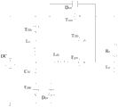
Solid circuit breaker (Solid State Circuit Breaker, be called for short SSCB) be a kind of novel electric power automation equipment for fast shut-off fault, because of its there is short, silent switching time, without electric arc, without turn-offing dead band, the life-span is long and functional reliability advantages of higher, has great application prospect.What use was more at present is alternating current solid-state circuit breaker.In direct current field, also have the DC solid circuit breaker of research based on thyristor, for example Chinese invention patent (patent No.: a kind of vibration shape DC solid circuit breaker of wiping 200910026473.8) providing, referring to Fig. 1.The key of its normal turn-off is energy storage pulsed capacitance C
10with inductance L
10there is the operating current that LC resonance and resonance current are greater than load, energy storage pulsed capacitance C in this structure
10with inductance L
10the necessary condition that LC resonance can occur is energy storage pulsed capacitance C
10voltage higher than power supply voltage, and due to the existence of thyristor ohmic leakage and capacity fall off resistance, will certainly cause energy storage pulsed capacitance C
10energy by thyristor T
220and T
230to load, leak, as energy storage pulsed capacitance C
10voltage while dropping to power supply voltage because of energy leakage, energy storage pulsed capacitance C
10with inductance L
10the necessary condition that does not reach resonance finally causes the shutoff of SSCB to lose efficacy; For this defect, propose to improve topology as Fig. 2, when this topology utilizes power supply voltage to reduce LC resonance to energy storage pulsed capacitance C
10the requirement of voltage, though efficiently solve the unreliable problem of shutoff causing because of the intrinsic leakage current of device, when short trouble turn-offs, because resonant tank has comprised power supply, power supply can flow through the resonance current that numerical value is very large, and power supply is caused to very large impact.
Based on aforementioned analysis, the inventor carries out Improvement for existing DC solid circuit breaker structure, and this case produces thus.
Summary of the invention
Technical problem to be solved by this invention, for the defect in aforementioned background art and deficiency, a kind of DC solid circuit breaker is provided, and its energy storage pulsed capacitance lower voltage that can effectively avoid causing because of the intrinsic leakage current of device turn-offs the unreliable and fault problem that power supply has very large resonance current to flow through while turn-offing.
The present invention is for solving above technical problem, and the technical scheme adopting is:
A kind of DC solid circuit breaker, comprise DC power supply and load, also comprise main switch unit A and auxiliary switching element B, wherein main switch unit A comprises: main switch thyristor and main switch power diode, and auxiliary switching element B comprises the first thyristor, the second thyristor, the 3rd thyristor, the 4th thyristor, the 5th thyristor, the 6th thyristor, the 7th thyristor, the first inductance, the second inductance, the first energy storage pulsed capacitance, the second energy storage pulsed capacitance, the first current-limited power resistance, the second current-limited power resistance and fly-wheel diode, the positive output end of DC power supply connects respectively the anode of the 6th thyristor, the anode of the first thyristor, the negative electrode of the anode of main switch thyristor and main switch power diode, the negative output terminal of DC power supply respectively with the negative electrode of the 7th thyristor, the anode of fly-wheel diode, the 4th negative electrode of thyristor and the negative input end of load are connected ground connection, the anode of main switch power diode connects respectively the negative electrode of main switch thyristor, the positive input terminal of load, the negative electrode of the negative electrode of the second thyristor and the 3rd thyristor, the input of the first energy storage pulsed capacitance connects respectively the negative electrode of the first thyristor, the input of the input of the first inductance and the second inductance, the output of the first energy storage pulsed capacitance connects respectively the negative electrode of the 5th thyristor and the input of the first current-limited power resistance, the anode of output termination the 4th thyristor of the first current-limited power resistance, the input of the second energy storage pulsed capacitance connects respectively the negative electrode of the 6th thyristor and the anode of the 5th thyristor, the output of the second energy storage pulsed capacitance connects respectively second input of current-limited power resistance and the negative electrode of fly-wheel diode, the anode of output termination the 7th thyristor of the second current-limited power resistance, the anode of output termination second thyristor of the first inductance, the output of the second inductance connects the anode of the 3rd thyristor.
Adopt after such scheme, beneficial effect of the present invention is as follows:
1,, from circuit structure reliability, effectively avoided the energy storage pulsed capacitance lower voltage causing because of the intrinsic leakage current of components and parts to turn-off insecure problem;
2, from short-circuit protection, the problem that when topological structure efficiently solves fault shutoff, power supply has very large resonance current to flow through;
3,, from turn-offing capacity, the scope inner breaker allowing at device can turn-off square being directly proportional of capacity and voltage.
Accompanying drawing explanation
Fig. 1 is a kind of main circuit structure figure of existing resonance type DC solid circuit breaker;
Fig. 2 is the improvement circuit structure diagram for the shortcoming proposition of the existence of circuit shown in Fig. 1;
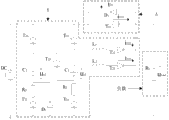
Fig. 3 is the main circuit structure figure of the DC solid circuit breaker that designs of the present invention;
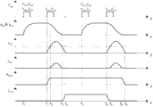
Fig. 4 normally turns on and off time sequential routine figure;
Fig. 5 is that time sequential routine figure is turn-offed in short circuit;
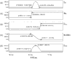
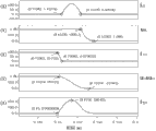
Fig. 6 is SSCB opening process oscillogram;
Fig. 7 is SSCB normal turn-off process oscillogram;
Fig. 8 is SSCB short circuit turn off process oscillogram.
Embodiment
Below with reference to accompanying drawing, technical scheme of the present invention is elaborated.
The invention provides a kind of DC solid circuit breaker, as shown in Figure 3, wherein A is main switch unit to its circuit, and B is auxiliary switching element.Wherein, main switch unit A comprises: main switch thyristor T
11with main switch power diode D
1; Auxiliary switching element B mainly comprises the first thyristor T
21, the second thyristor T
22, the 3rd thyristor T
23, the 4th thyristor T
24, the 5th thyristor T
25, the 6th thyristor T
26, the 7th thyristor T
27, the first inductance L
1, the second inductance L
2, the first energy storage pulsed capacitance C
1, the second energy storage pulsed capacitance C
2, the first current-limited power resistance R
1, the second current-limited power resistance R
2and sustained diode
2.
Wherein auxiliary switch B can be divided into again by function and combination:
(1) first auxiliary charging circuit: the first thyristor T
21, the first energy storage pulsed capacitance C
1, the first current-limited power resistance R
1, the 4th thyristor T
24form;
(2) second auxiliary charging circuits: the 6th thyristor T
26, the second energy storage pulsed capacitance C
2, the second current-limited power resistance R
2, the 7th thyristor T
27form;
(3) the auxiliary circuit of opening: sustained diode
2, the second energy storage pulsed capacitance C
2, the 5th thyristor T
25, the first energy storage pulsed capacitance C
1, the first inductance L
1, the second thyristor T
22form;
(4) normal turn-off circuit: sustained diode
2, the second energy storage pulsed capacitance C
2, the 5th thyristor T
25, the first energy storage pulsed capacitance C
1, the first inductance L
1, the second thyristor T
22form;
(5) fault judging circuit: sustained diode
2, the second energy storage pulsed capacitance C
2, the 5th thyristor T
25, the first energy storage pulsed capacitance C
1, the second inductance L
2, the 3rd thyristor T
23form;
Below introduce the operation principle of DC solid circuit breaker provided by the present invention:
First open the first thyristor T
21, the 4th thyristor T
24, the 6th thyristor T
26with the 7th thyristor T
27respectively to the first energy storage pulsed capacitance C
1, the second energy storage pulsed capacitance C
2charge to power supply voltage, then open the 5th thyristor T
25with the second thyristor T
22, make the first energy storage pulsed capacitance C
1, the second energy storage pulsed capacitance C
2with the first inductance L
1there is LC resonance, when resonance current increases to after loaded work piece electric current, main switch power diode D
1start afterflow; As main switch power diode D
1in freewheel current open main switch thyristor T while being reduced to zero
11; Main switch thyristor T
11electric current along with reducing of resonance current, increase; When resonance current is reduced to zero, main switch thyristor T
11electric current reach stationary value, opening process finishes.
When solid circuit breaker SSCB needs normal disconnection, open the 5th thyristor T
25, the second thyristor T
22, the first energy storage pulsed capacitance C
1, the second energy storage pulsed capacitance C
2by the first inductance L
1there is LC resonance; Along with the increase of resonance current, main switch thyristor T
11electric current reduces, when resonance current is greater than load current, and main switch thyristor T
11thereby electric current drops to zero and realizes nature shutoff, and resonance current redundance is from main switch power two utmost point rate D
1afterflow, when resonance current returns while being down to zero, turn off process finishes.
When solid circuit breaker SSCB needs fault to disconnect, open the 5th thyristor T
25with the 3rd thyristor T
23, the first energy storage pulsed capacitance C
1, the second energy storage pulsed capacitance C
2by the second inductance L
2there is LC resonance, the second inductance L
2value is compared with the first inductance L
1much smaller, the resonance current rate of climb is faster than the fault current rate of climb, as main switch power diode D
1while having electric current to return, by main switch thyristor T
11electric current reduce to zero, thereby shutoff naturally.
During normal work, circuit working state is analyzed:
In Fig. 4, t
0control system is sent the first energy storage pulsed capacitance C constantly
1, the second energy storage pulsed capacitance C
2charging instruction, power supply passes through RC circuit to the first energy storage pulsed capacitance C
1, the second energy storage pulsed capacitance C
2charging, the first energy storage pulsed capacitance C
1, the second energy storage pulsed capacitance C
2charge to the t after power supply voltage
1time trigger the 5th thyristor T
25, the second thyristor T
22, the first energy storage pulsed capacitance C
1, the second energy storage pulsed capacitance C
2, the first inductance L
1with load, RLC resonance occurs, resonance current is started from scratch and is increased gradually.
T
2constantly, resonance current increases to loaded work piece electric current, and when resonance current continues to increase, remainder is from main switch power diode D
1afterflow, now flows through the electric current I of load
n, main switch power diode D
1current i
d1flow through the second thyristor T with resonance current
22current i
t22pass be i
t22=I
n+ i
d1; Flow through main switch power diode D
1electric current along with the continuation of resonance, increase, reach after peak value and start to fall after rise, t
3constantly fall after rise to load current, now to main switch thyristor T
11send and open signal, at t
3to t
4time period, flow through main switch thyristor T
11current i
t11with loaded work piece electric current I
nwith flow through the second thyristor T
22current i
t22pass be i
t11=I
n+ i
t22, loaded work piece electric current I
nremain constant, flow through main switch thyristor T
11current i
t11along with reducing of resonance current, increase, when resonance current drops to zero, flow through main switch thyristor T
11electric current increase to loaded work piece electric current I
nthereby, realize zero current (pressure) open-minded; T after opening
5constantly again send the first energy storage pulsed capacitance C
1, the second energy storage pulsed capacitance C
2charging instruction, prepares for solid circuit breaker turn-offs.
In Fig. 4, t
4to t
6in time period, circuit, in normal operating condition, is established t
6the initial time of normal turn-off constantly.
At t
6control system is sent normal turn-off order, the 5th thyristor T constantly
25with the second thyristor T
22conducting, the first energy storage pulsed capacitance C
1, the second energy storage pulsed capacitance C
2with the first inductance L
1there is LC resonance; At t
6to t
7time period, resonance current does not increase to loaded work piece electric current, by main switch thyristor T
11current i
t11, by the second thyristor T
22current i
t22with loaded work piece electric current I
npass be I
n=i
t11+ i
t22, loaded work piece electric current I
nremain constant, main switch thyristor i
t11electric current along with the increase of resonance current, reduce, and at t
7thereby constantly along with resonance current increases to loaded work piece electric current, being decreased to zero turn-offs naturally; After this resonance current starts to be greater than loaded work piece electric current, is greater than the part electric current of load from main switch power diode D
1flow away; Main switch power diode D
1between the afterflow period, energy storage pulsed capacitance C
1, C
2an energy part for storage is by load consumption, and a part is from main switch power diode D
1feed back to power supply; As main switch power diode D
1in freewheel current along with resonance current reaches when falling after rise after peak value and dropping to zero, energy storage pulsed capacitance C
1, C
2with the first inductance L
1, load R
lthere is RLC resonance, when this resonance current drops to a zero hour deterministic process, finish.
When short circuit is turn-offed, circuit working state is analyzed:
For the integrality of maintained switch operating process, with t '
5constantly represent the moment that short circuit is turn-offed, as shown in Figure 5.
T '
5constantly flow through main switch thyristor T
11current i
t11(t '
5)=I
n, t '
5back loading starts to occur overcurrent constantly, flows through main switch thyristor T
11electric current increase rapidly.
T '
6constantly, flow through main switch thyristor T
11electric current reach the short circuit current protection multiple of setting, now trigger the 5th thyristor T
25with the 3rd thyristor T
23open-minded, the first energy storage pulsed capacitance C
1, the second energy storage pulsed capacitance C
2by the second inductance L
2resonant discharge, flows through the 3rd thyristor T
23current i
t23(t '
6)=0, because the speed rising of discharging current is very fast, flows through main switch thyristor T
11electric current start to decline.
T '
7constantly, the discharging current of resonance branch road is greater than short circuit current, flows through main switch thyristor T
11electric current be reduced to zero, main switch thyristor T
11naturally turn-off, with main switch thyristor T
11antiparallel main switch power diode D
1start the remaining electric current of afterflow.
T '
8constantly, main switch power diode D
1in electric current be reduced to zero, its afterflow process finishes; T '
9constantly, flow through the 3rd thyristor T
23current i
t23drop to zero, fault turn off process finishes.
The parameter designing in an example of the present invention:
Line voltage distribution V
dC=1000V, circuit rated current I
n=100A, load resistance R
l=10 Ω;
Energy storage pulsed capacitance C
1=200 μ F, the first inductance L
1=4mH, the second inductance L
2=80 μ H;
Fig. 6, Fig. 7, Fig. 8 are that the designed circuit of the present invention is normally opened while adopting the parameter of design, normal turn-off and fault are turn-offed corresponding oscillogram in three kinds of situations.
Main switch thyristor T in the present embodiment
11, main switch power diode D
1, the first thyristor T
21, the second thyristor T
22, the 3rd thyristor T
23, the 4th thyristor T
24, the 5th thyristor T
25, the 6th thyristor T
26, the 7th thyristor T
27, sustained diode
2all adopt ripe conventional products.
In sum; although basic structure of the present invention, principle, method are specifically set forth by above-described embodiment; do not departing under the prerequisite of main idea of the present invention; according to above-described inspiration, those of ordinary skills can not need to pay creative work and can implement conversion/alternative form or combine all to fall in protection range of the present invention.
Claims (1)
1. a DC solid circuit breaker, is connected between DC power supply and load, it is characterized in that: also comprise main switch unit A and auxiliary switching element B, wherein main switch unit A comprises: main switch thyristor and main switch power diode, and auxiliary switching element B comprises the first thyristor, the second thyristor, the 3rd thyristor, the 4th thyristor, the 5th thyristor, the 6th thyristor, the 7th thyristor, the first inductance, the second inductance, the first energy storage pulsed capacitance, the second energy storage pulsed capacitance, the first current-limited power resistance, the second current-limited power resistance and fly-wheel diode, the positive output end of DC power supply connects respectively the anode of the 6th thyristor, the anode of the first thyristor, the negative electrode of the anode of main switch thyristor and main switch power diode, the negative output terminal of DC power supply respectively with the negative electrode of the 7th thyristor, the anode of fly-wheel diode, the 4th negative electrode of thyristor and the negative input end of load are connected ground connection, the anode of main switch power diode connects respectively the negative electrode of main switch thyristor, the positive input terminal of load, the negative electrode of the negative electrode of the second thyristor and the 3rd thyristor, the input of the first energy storage pulsed capacitance connects respectively the negative electrode of the first thyristor, the input of the input of the first inductance and the second inductance, the output of the first energy storage pulsed capacitance connects respectively the negative electrode of the 5th thyristor and the input of the first current-limited power resistance, the anode of output termination the 4th thyristor of the first current-limited power resistance, the input of the second energy storage pulsed capacitance connects respectively the negative electrode of the 6th thyristor and the anode of the 5th thyristor, the output of the second energy storage pulsed capacitance connects respectively second input of current-limited power resistance and the negative electrode of fly-wheel diode, the anode of output termination the 7th thyristor of the second current-limited power resistance, the anode of output termination second thyristor of the first inductance, the output of the second inductance connects the anode of the 3rd thyristor.
Priority Applications (1)
| Application Number | Priority Date | Filing Date | Title |
|---|---|---|---|
| CN201110154838.2A CN102222874B (en) | 2011-06-10 | 2011-06-10 | Direct-current solid-state circuit breaker |
Applications Claiming Priority (1)
| Application Number | Priority Date | Filing Date | Title |
|---|---|---|---|
| CN201110154838.2A CN102222874B (en) | 2011-06-10 | 2011-06-10 | Direct-current solid-state circuit breaker |
Publications (2)
| Publication Number | Publication Date |
|---|---|
| CN102222874A CN102222874A (en) | 2011-10-19 |
| CN102222874B true CN102222874B (en) | 2014-04-09 |
Family
ID=44779336
Family Applications (1)
| Application Number | Title | Priority Date | Filing Date |
|---|---|---|---|
| CN201110154838.2A Expired - Fee Related CN102222874B (en) | 2011-06-10 | 2011-06-10 | Direct-current solid-state circuit breaker |
Country Status (1)
| Country | Link |
|---|---|
| CN (1) | CN102222874B (en) |
Families Citing this family (6)
| Publication number | Priority date | Publication date | Assignee | Title |
|---|---|---|---|---|
| CN103280763B (en) | 2013-02-27 | 2016-12-28 | 国网智能电网研究院 | A kind of dc circuit breaker and its implementation |
| CN106159880B (en) * | 2015-03-27 | 2019-07-12 | 积能环保电机工程科技有限公司 | DC solid circuit breaker and distribution system |
| CN105514929A (en) * | 2016-01-05 | 2016-04-20 | 南京航空航天大学 | Self-power direct current solid state circuit breaker based on normal open type SiC device |
| CN105552828A (en) * | 2016-01-05 | 2016-05-04 | 南京航空航天大学 | Self-powered bidirectional direct-current solid-state circuitbreaker |
| CN107342754B (en) * | 2017-06-28 | 2020-07-14 | 上海交通大学 | Direct current breaker based on coupling inductance coil and control method thereof |
| CN112821372B (en) * | 2021-03-12 | 2022-05-31 | 南京航空航天大学 | Forward feedback type absorption circuit for improving efficiency of direct-current solid-state circuit breaker |
Citations (2)
| Publication number | Priority date | Publication date | Assignee | Title |
|---|---|---|---|---|
| US5561579A (en) * | 1994-11-04 | 1996-10-01 | Electric Power Research Institute, Inc. | Solid-state circuit breaker with fault current conduction |
| CN101540493A (en) * | 2009-04-22 | 2009-09-23 | 南京航空航天大学 | Resonance type DC solid circuit breaker |
Family Cites Families (1)
| Publication number | Priority date | Publication date | Assignee | Title |
|---|---|---|---|---|
| CN101340185B (en) * | 2008-08-26 | 2011-03-30 | 南京航空航天大学 | Synchronous control method of 3 phase AC solid power controller |
-
2011
- 2011-06-10 CN CN201110154838.2A patent/CN102222874B/en not_active Expired - Fee Related
Patent Citations (2)
| Publication number | Priority date | Publication date | Assignee | Title |
|---|---|---|---|---|
| US5561579A (en) * | 1994-11-04 | 1996-10-01 | Electric Power Research Institute, Inc. | Solid-state circuit breaker with fault current conduction |
| CN101540493A (en) * | 2009-04-22 | 2009-09-23 | 南京航空航天大学 | Resonance type DC solid circuit breaker |
Also Published As
| Publication number | Publication date |
|---|---|
| CN102222874A (en) | 2011-10-19 |
Similar Documents
| Publication | Publication Date | Title |
|---|---|---|
| CN107342754B (en) | Direct current breaker based on coupling inductance coil and control method thereof | |
| CN101540493B (en) | Resonance type DC solid circuit breaker | |
| CN102222874B (en) | Direct-current solid-state circuit breaker | |
| CN104137211B (en) | There is the high voltage direct current hybrid circuit breaker of buffer circuit | |
| CN108599120B (en) | Direct current limiting circuit breaker | |
| CN113345741B (en) | DC arc-extinguishing device | |
| CN107534438A (en) | DC solid circuit breaker and distribution system | |
| CN110138360B (en) | High-efficient pulse power generating circuit of demagnetization switch based on RSD | |
| CN102064047B (en) | Relay and switching tube parallel circuit suitable for high-pressure direct current occasion | |
| CN105428117A (en) | Arc extinguishing device | |
| CN110518545B (en) | Hybrid high-voltage direct-current circuit breaker based on bidirectional current limiting module | |
| CN106024497A (en) | Auxiliary circuit for high-short-circuit turn-off direct current circuit breaker and control method for auxiliary circuit | |
| CN111585266A (en) | DC distribution electronic soft start switch | |
| CN106849327B (en) | Alternating current-direct current hybrid circuit breaker and control method | |
| CN202276128U (en) | Resonance type DC solid state breaker | |
| CN202650896U (en) | High voltage direct current hybrid circuit breaker with buffer circuit | |
| CN203984229U (en) | A kind of by-pass switch trigger equipment of MMC flexible DC power transmission submodule | |
| AU2019341286B2 (en) | Arc-extinguishing circuit and apparatus | |
| CN110880745B (en) | Active resistance-capacitance type direct current limiter based on double-capacitance oscillation and control method | |
| CN110829360B (en) | Method for controlling high-voltage direct-current circuit breaker by hardware integrated circuit | |
| CN102064549A (en) | Switching method and switching switch circuit of AC capacitor | |
| Komatsu et al. | A solid-state current limiting switch for application of large-scale space power systems | |
| CN217935137U (en) | Hierarchical load switching circuit controlled by BMS | |
| CN112753084B (en) | Alternating current arc extinguishing circuit, device and switching system | |
| CN112740352B (en) | Arc extinguishing circuit, arc extinguishing device and switch system |
Legal Events
| Date | Code | Title | Description |
|---|---|---|---|
| C06 | Publication | ||
| PB01 | Publication | ||
| C10 | Entry into substantive examination | ||
| SE01 | Entry into force of request for substantive examination | ||
| C14 | Grant of patent or utility model | ||
| GR01 | Patent grant | ||
| CF01 | Termination of patent right due to non-payment of annual fee |
Granted publication date: 20140409 Termination date: 20170610 |
|
| CF01 | Termination of patent right due to non-payment of annual fee |