EP2962920B1 - Rahmanschloss und verfahren zur herstellung eines rahmenschloss - Google Patents
Rahmanschloss und verfahren zur herstellung eines rahmenschloss Download PDFInfo
- Publication number
- EP2962920B1 EP2962920B1 EP15175432.2A EP15175432A EP2962920B1 EP 2962920 B1 EP2962920 B1 EP 2962920B1 EP 15175432 A EP15175432 A EP 15175432A EP 2962920 B1 EP2962920 B1 EP 2962920B1
- Authority
- EP
- European Patent Office
- Prior art keywords
- lock cap
- legs
- capacitor discharge
- rear lock
- front lock
- Prior art date
- Legal status (The legal status is an assumption and is not a legal conclusion. Google has not performed a legal analysis and makes no representation as to the accuracy of the status listed.)
- Active
Links
Images



Classifications
-
- B—PERFORMING OPERATIONS; TRANSPORTING
- B62—LAND VEHICLES FOR TRAVELLING OTHERWISE THAN ON RAILS
- B62H—CYCLE STANDS; SUPPORTS OR HOLDERS FOR PARKING OR STORING CYCLES; APPLIANCES PREVENTING OR INDICATING UNAUTHORIZED USE OR THEFT OF CYCLES; LOCKS INTEGRAL WITH CYCLES; DEVICES FOR LEARNING TO RIDE CYCLES
- B62H5/00—Appliances preventing or indicating unauthorised use or theft of cycles; Locks integral with cycles
- B62H5/14—Appliances preventing or indicating unauthorised use or theft of cycles; Locks integral with cycles preventing wheel rotation
- B62H5/147—Appliances preventing or indicating unauthorised use or theft of cycles; Locks integral with cycles preventing wheel rotation by means of circular bolts
Definitions
- the invention relates to a method for manufacturing a ring lock which can be applied to a cycle, such as a bicycle, an electric bicycle, a moped, a go-cart, or like vehicles.
- a ring lock with a welded connection is known from inter alia the publications DE25 19 068 , NL 1.021.598 and EP 1.834.864 .
- EP 1.834.864 discloses a method having the features which are mentioned in the pre-characterizing portion of claim 1.
- the front lock cap legs, the rear lock cap legs, the front lock cap body and the rear lock cap body are provided with outwardly directed circumferential flanges which are configured to adjoin each other and to be welded together by laser welding or spot welding.
- the disadvantage of a traditional spot welding technique is that it leads to a substantial heat generation in the lock and may thereby lead to damage of parts included between the front lock cap and the rear lock cap.
- the lock caps themselves too may be damaged by the known spot welding process, so that, for instance, a protective coating, such as, for example, a zinc coating, is damaged and an extra processing operation for applying a protective coating after the welding process is necessary.
- a protective coating such as, for example, a zinc coating
- the spot (weld) that is welded mostly has a diameter of 4 to 5 times the plate thickness.
- the spot welds are mutually spaced apart and between the spot welds the front and rear caps are not connected with each other. This creates the possibility of applying a breaking tool between the spot welds in order to break the lock open.
- spot welds are not provided in one go but in a number of welding operations. Only one or two spots at a time can be welded per welding operation. Providing the spot welds is therefore time consuming and hence costly. Also, it is not possible to connect end edges of the steel directly to each other by spot welding.
- the invention provides the method of claim 1 for manufacturing a ring lock.
- the invention has a number of advantages over DE25 19 068 and EP1834864 .
- capacitor discharge welding less heat is induced than in spot welding, so that the temperature increase of the front lock cap and rear lock cap and of the parts at least partly included therein, is small.
- capacitor discharge welding entire continuous contours can be welded in one go. Differences in material and plate thickness in the various welding areas are much less of influence on the capacitor discharge weld process. With the aid of capacitor discharge welding it is possible to connect the entire circumferential contour of the lock by a capacitor discharge weld connection in one capacitor discharge welding operation.
- EP1834864 discloses that one particularity of the invention consists of the fact that, towards the outside, said front and rear half-housings form respective peripheral edges that are capable of resting on one anouther and bing joined by welding....
- the drawings of EP1834864 disclose that the peripheral edges are circumferential flanges as discussed above.
- the capacitor discharge weld connection is a continuous connection and not, as with spot welding, a local connection, where in effect there is no connection between the spot welds.
- the rear lock cap and/or the front lock cap may be provided with at least one indentation which in a condition of the front lock cap and the rear lock cap placed on each other prior to the capacitor discharge weld process forms a contact surface that is configured as a line contact between the front lock cap and the rear lock cap, wherein in the condition of the front lock cap and the rear lock cap placed on each other the two caps touch each other via the line contacts, and wherein after the capacitor discharge weld process at the line contacts mentioned a capacitor discharge weld connection is formed between the front lock cap and the rear lock cap.
- the contact surface configured as line contact has a small surface, so that the heat generation thereat is optimal, while the transmitted electric power is relatively small.
- the amount of heat energy, however, owing to the small contact surface is relatively small, with the advantage that the conduction of the heat to the contiguous parts of the lock is small. As a result, damage of lock parts or of the front lock cap and/or rear lock cap will not readily occur.
- Another advantage of a capacitor discharge weld connection formed from the line contact connection is that this creates a continuous connection zone without interruptions. Breaking open such a continuous connection zone is practically impossible.
- the front lock cap legs and the rear lock cap legs may be provided with outer flanges which have an outer flange length that corresponds substantially to a length of the leg associated with a respective outer flange, while an at least one indentation is provided in at least one of two opposite outer flanges such that at the at least one indentation prior to the capacitor discharge weld process a line contact is formed between opposite outer flanges of a front lock cap and a rear lock cap, respectively, and following the capacitor discharge weld process at the line contact mentioned a capacitor discharge weld connection is formed which connects the opposite outer flanges with each other substantially along the entire outer flange length.
- a further advantage of a robust connection can be achieved by providing the front lock cap legs and the rear lock cap legs with inner flanges, while an at least one indentation is provided in at least one of two opposite inner flanges such that at the at least one indentation prior to the capacitor discharge weld process a line contact is formed between opposite inner flanges of a front lock cap and a rear lock cap, respectively, and following the capacitor discharge weld process at the at least one line contact a capacitor discharge weld connection is formed.
- the firm connection at the inner flanges also contributes to a good basis for connecting the ring lock with, for example, a bicycle which it may be a part of.
- the front lock cap body and the rear lock cap body may be provided with mutually facing plate end edges which prior to the capacitor discharge weld process form a contact surface, and following the capacitor discharge weld process at the mutually facing plate end edges at least one capacitor discharge weld connection is formed.
- the front lock cap body and the rear lock cap body are not provided with a circumferential flange but the mutually facing plate end edges are connected with each other directly by the capacitor discharge weld connection.
- the lock can also be mounted on cycles where the mounting space is relatively limited.
- the end plate end edge connection and the line contact connection at the front lock cap legs and rear lock cap legs can be realized in a single capacitor discharge welding operation - that is, in a single current surge. The production time is therefore particularly short, while the connection between the front lock cap and the rear lock cap is much better resistant to sabotage and breaking.
- the mutually facing plate end edges can extend substantially along the entire circumference of the front lock cap and the rear lock cap to form the contact surface which, following the capacitor discharge weld process, forms the capacitor discharge weld connection. That is to say, both at the body and at the legs. In that case, the provision of indentations may be dispensed with. All capacitor discharge weld connections can be formed at mutually facing plate end edges.
- the front lock cap legs and the rear lock cap legs do not need to be provided with outer flanges, which yields a saving of material.
- the inner flanges necessary anymore for establishing a connection between the front lock cap and the rear lock cap. Such inner flanges, however, may still be of benefit for the purpose of mounting the ring lock to a cycle.
- the front lock cap and the rear lock cap may be provided with at least one opening for connecting the front lock cap and rear lock cap by means of rivets.
- the front lock cap and the rear lock cap may each be manufactured by at least one punching operation from plate material extending in a plate plane, whereby in the at least one punching operation there are formed:
- the punching operation makes for lower manufacturing costs.
- the (automated) punching operation makes it possible to provide the lock caps in one processing operation with all form features advantageous for capacitor discharge welding, such as the above-described indentations and/or the above-described mutually facing plate end edges to form contact surfaces with a particularly small total contact surface.
- the advantage of the method according to the invention is that in capacitor discharge welding heat is supplied very locally. As a result, the firmness of a welded connection is realized without the parts included between the front lock cap and rear lock cap, viz., the bolt and the lock housing with lock assembly included therein, sustaining a large increase of temperature.
- the very local supply of heat provides the advantage that the on-site heat generation is optimal, at a relatively low transmitted electric power.
- the method according to the invention has the advantage that it is possible to connect the entire outer circumferential contour of the lock with each other substantially along the entire length thereof with a single current surge. This in contrast to the spot welded connections that are made in the lock known from DE 25 19 068 .
- spot welds are provided singly, and between the spot welds the front lock cap and the rear lock cap are not connected with each other, so that with this known lock breaking open the lock by prying a screwdriver between two neighboring spot welds is one of the possibilities.
- the lock cap legs formed by the front lock cap legs and the rear lock cap legs, as well as the lock cap body, formed by the front lock cap body and the rear lock cap body, may each be provided with at least one contact surface that extends along substantially the entire outer contour of the lock cap legs and along substantially the entire outer contour of the lock cap body.
- the lock cap formed by the front lock cap and the rear lock cap, is provided at at least three places, more particularly along the entire outer contour, with a capacitor discharge weld connection which makes breaking open the lock more difficult.
- the contact surfaces are formed by line contacts and/or mutually facing plate end edges, with a total contact surface of less than 700 mm 2 , preferably less than 500 mm 2 .
- contact surfaces in the form of line contacts or mutually facing plate end edges with a total contact surface of less than 700 mm 2 and preferably less than 500 mm 2 , a high local heat supply can be attained at a relatively low electric power.
- a limited contact surface also leads to a limited temperature increase in the other parts of the lock cap during welding, so that damage of parts in the lock cap is avoided.
- the at least one contact surface may be formed exclusively by mutually facing plate end edges, which extend substantially along the entire circumferential length of the front lock cap and the rear lock cap. Both at the body and at the legs, the contact surface is then formed by mutually facing plate end edges which after the capacitor discharge weld process form the capacitor discharge weld connection. The provision of indentations then is not necessary anymore and also the presence of outer flanges can be dispensed with.
- connection between the front lock cap and the rear lock cap does not constitute a bottleneck in the production process because it merely comprises placing the two caps on each other, pressing-on, and transmitting a large current surge through the two caps.
- At least one indentation may be provided which, in a condition of the front lock cap and rear lock cap placed on each other, forms a contact surface between the front lock cap and the rear lock cap.
- the front lock cap and the rear lock cap are pressed onto each other with a force of at least 80 kN. This force contributes to the bringing about of a good capacitor discharge weld connection.
- the surface area of the contact surfaces is so small that during the capacitor discharge welding the generation of heat in the front lock cap and the rear lock cap occurs only locally and, as a result, the increase of temperature of the bolt and the lock housing with the lock assembly included therein is less than 50 °C and preferably less than 40 °C. By staying below this temperature increase in the method, damage of the lock parts, among which the bolt and the lock housing including lock assembly, is prevented.
- Fig. 1 is a front view of an example of a ring lock 1 prior to the provision of the capacitor discharge weld connections.
- a ring lock 1 with a front lock cap 2 with front lock cap legs 4a, which are connected with a front lock cap body 5a, which partly encompass a bolt 11 and a lock housing with a lock assembly included therein (not shown).
- the figure also shows outer flanges 7, having an outer flange length extending along the entire length of the outer flange, and inner flanges 8 of the front lock cap 2. Also shown are the openings 9 in which rivets may be provided.
- Fig. 2 is a rear view of the ring lock 1 shown in Fig. 1 .
- a rear lock cap 3 is visible with rear lock cap legs 4b, which are connected with a rear lock cap body 5b.
- outer flanges 7 of the rear lock cap legs 4a are shown, with an indentation 6a extending along the entire length thereof.
- indentations 6b in inner flanges 8 of the rear lock cap legs 4b are also the openings 9 for fitting rivets.
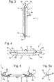
- Fig. 3 shows a side view of the ring lock 1 of Fig. 1 prior to the provision of the capacitor discharge weld connections.
- the contact surfaces between the front lock cap 2 and rear lock cap 3 are represented. These are formed in this example by:
- Fig. 4 is a top plan view of the example of the ring lock 1 represented in Fig. 1 prior to the provision of the capacitor discharge weld connections, also showing the plate end edges 10, bent towards each other, of the front lock cap body 5a and the rear lock cap body 5b. Also visible are the contact surfaces, formed by the indentations 6a in the outer flanges 7 of the rear lock cap 3, at which the front lock cap legs 4a and rear lock cap legs 4b touch each other.
- Fig. 5 is a cross-sectional view along the line V-V in Fig. 1 prior to the provision of the capacitor discharge weld connections.
- the depicted ring lock 1 with a front lock cap 2 and a rear lock cap 3 is provided with indentations 6a, 6b in the outer flanges 7 and inner flanges 8, respectively, which form a line contact indentation 6a between the front lock cap 2 and the rear lock cap 3.
- the line contacts mentioned form the contact surfaces at which the capacitor discharge weld connection is formed.
- a detailed view of the contact surface between the outer flanges 7 of the front lock cap legs 4a and the rear lock cap legs 4b, formed by the indentation 6a, is represented in Fig. 5a .
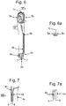
- Fig. 6 is a cross-sectional view along the line VI-VI in Fig. 1 , prior to the provision of the capacitor discharge weld connections.
- Fig. 6 shows the front lock cap body 5a and the rear lock cap body 5b with the mutually facing plate end edges 10 thereat forming a contact surface.
- An enlargement of the contact surface in detail VIa is given in Fig. 6a .
- the contact surface between the outer flanges 7 of the front cap legs 4a and the rear lock cap legs 4b formed by the indentation 6a.
- the contact surface between the inner flanges 8 of the front lock cap legs 4a and the rear lock cap legs 4b, formed by the indentation 6b is visible.
- Fig. 7 is a cross-sectional view along the line VII-VII in Fig. 2 .
- Fig. 7 shows an indentation 6b between the inner flanges 8 of the front lock cap legs 4a and the rear lock cap legs 4b.
- An enlargement of the indentation 6b in detail VIIa is represented in Fig. 7a .
- Figs. 8-12a show an example of the ring lock after the provision of the capacitor discharge weld connections.
- Fig. 8 is a side view of the example of the ring lock 1 after the provision of the capacitor discharge weld connections.
- the front lock cap 2 and rear lock cap 3 are connected to each other, with a contact surface provided at the lock cap body 5 and the lock cap legs 4.
- the lock cap body 5 is connected at the plate end edges 10 with a capacitor discharge weld connection, and the outer flanges 7 are mutually connected along an entire outer flange length of the outer flanges 7 through a capacitor discharge weld connection.
- Fig. 9 is a top plan view of the example of the ring lock after provision of the capacitor discharge weld connections.
- the front lock cap body 5a and the rear lock cap body at the plate end edges 10 which form a contact surface and are connected there by a capacitor discharge weld connection.
- the line contacts between the outer flanges 7 of the front lock cap legs 4a and the rear lock cap legs 4b which are connected with a capacitor discharge weld connection along the entire outer flange length.
- Fig. 10 is a cross-sectional view along the line V-V in Fig. 1 , but now after the provision of the capacitor discharge weld connections. It is clearly visible that the front lock cap 2 and rear lock cap 3 are connected at the indentations 6a, 6b in the outer flanges 7 and inner flanges 8, respectively, through a capacitor discharge weld connection. An enlargement of the capacitor discharge weld connection between the outer flanges 7 of the front lock cap legs 4a and the outer flanges of the rear lock cap legs 4b at the indentation 6a is represented in Fig. 10a .
- Fig. 11 is a cross section along the line VI-VI in Fig. 1 , but now after the provision of the capacitor discharge weld connections.
- the figure shows the front lock cap body 5a and the rear lock cap body 5b with the mutually facing plate end edges 10 which form a contact surface at which a capacitor discharge weld connection is formed.
- An enlargement of the capacitor discharge weld connection at the mutually facing plate end edges 10 is shown in Fig. 11a.
- Fig. 11 also shows the capacitor discharge weld connection between the outer flanges 7 of the front lock cap legs 4a and the rear lock cap legs 4b.
- Fig. 12 is a cross-sectional view along the line VII-VII in Fig. 2 , but now after provision of the capacitor discharge weld connections.
- Fig. 12 shows the capacitor discharge weld connection at the indentation 6b between the inner flanges 8 of the front lock cap legs 4a and the rear lock cap legs 4b.
- An enlargement of that capacitor discharge weld connection at the indentation 6b in detail VIIa is given in Fig. 12a .
- capacitor discharge welding for a short length of time a large electric current is conducted through the contact surfaces, formed by the indentations 6a, 6b and the mutually facing plate end edges 10, to form a capacitor discharge weld connection, such that the front lock cap 2 and the rear lock cap 3 are connected with each other by the capacitor discharge weld connections.
Landscapes
- Engineering & Computer Science (AREA)
- Mechanical Engineering (AREA)
- Fixed Capacitors And Capacitor Manufacturing Machines (AREA)
Claims (4)
- Verfahren zur Herstellung eines Ringschlosses (1), umfassend:- ein Schlossgehäuse mit einer darin enthaltenen Schlossbaugruppe;- einen Bolzen (11);- eine vordere Schlosskappe (2) mit zwei vorderen Schlosskappenschenkeln (4a), die mit einem vorderen Schlosskappenkörper (5a) verbunden sind; und- eine hintere Schlosskappe (3) mit zwei hinteren Schlosskappenschenkeln (4b), die mit einem hinteren Schlosskappenkörper (5b) verbunden sind;
wobei das Verfahren wenigstens umfasst:- Positionieren des Schlossgehäuses, so dass es sich im Wesentlichen zwischen dem vorderen Schlosskappenkörper (5a) und dem hinteren Schlosskappenkörper (5b) befindet,- Positionieren des Bolzens (11), so dass er sich durch das Schlossgehäuse erstreckt und wenigstens teilweise zwischen den vorderen Schlosskappenschenkeln (4a) und den hinteren Schlosskappenschenkeln (4b) enthalten ist,- Positionieren der vorderen Schlosskappe (2) und der hinteren Schlosskappe (3), so dass sie mit Kontaktflächen gegeneinanderstoßen,- die Schlosskappenschenkel (4), die durch die vorderen Schlosskappenschenkel (4a) und die hinteren Schlosskappenschenkel (4b) gebildet werden, sowie einen Schlosskappenkörper (5), der durch den vorderen Schlosskappenkörper (5a) und den hinteren Schlosskappenkörper (5b) gebildet wird, wobei jeder mit wenigstens einer Kontaktfläche versehen ist, die sich entlang der gesamten Außenkontur der Schlosskappenschenkel (4) und entlang der gesamten Außenkontur des Schlosskappenkörpers (5) erstreckt,- Drücken der vorderen Schlosskappe (2) und der hinteren Schlosskappe (3) gegeneinander, und- Zusammenschweißen der vorderen Schlosskappe (2) und der hinteren Schlosskappe (3) an den Kontaktflächen;
dadurch gekennzeichnet, dass
das Schweißen Kondensatorentladungsschweißen ist, wobei mit einem einzigen Stromstoß für kurze Zeitdauer ein elektrischer Strom durch die vordere Schlosskappe und die hintere Schlosskappe über die Kontaktflächen geleitet wird, wobei die Zeitdauer und die Höhe des Stroms und der Spannung so sind, dass an allen Kontaktflächen das Material der
vorderen Schlosskappe und der hinteren Schlosskappe miteinander verschmilzt, und dort eine Kondensatorentladungsschweißverbindung gebildet wird, wobei beim Kondensatorentladungsschweißen die vordere Schlosskappe (2) und die hintere Schlosskappe (3) mit einer Kraft von wenigstens 80 kN aufeinander gepresst werden, wobei die Kontaktflächen durch Linienkontakte und/oder einander zugewandte Plattenendkanten (10) gebildet werden, mit einer Gesamtkontaktfläche von weniger als 700 mm2 und vorzugsweise weniger als 500 mm2, und wobei die Oberfläche der Kontaktflächen so klein ist, dass beim Kondensatorentladungsschweißen die Wärmeentwicklung in der vorderen Schlosskappe (2) und der hinteren Schlosskappe (3) nur lokal auftritt und dadurch der Temperaturanstieg des Bolzens (11) und des Schlossgehäuses mit der darin enthaltenen Schlossbaugruppe weniger als 50 °C und vorzugsweise weniger als 40 °C beträgt. - Verfahren nach Anspruch 1, wobei die wenigstens eine Kontaktfläche ausschließlich durch einander zugewandte Plattenendkanten (10) gebildet wird, die sich im Wesentlichen entlang der gesamten Umfangslänge der vorderen Schlosskappe (5a) und der hinteren Schlosskappe (5b) erstrecken.
- Verfahren nach einem der Ansprüche 1 bis 2, wobei in der vorderen Schlosskappe (2) und/oder der hinteren Schlosskappe (3) wenigstens eine Vertiefung (6) vorgesehen ist, die in einem Zustand, in dem die vordere Schlosskappe (2) und die hintere Schlosskappe (3) aufeinandergesetzt sind, eine Kontaktfläche zwischen der vorderen Schlosskappe (2) und der hinteren Schlosskappe (3) bildet.
- Verfahren nach einem der Ansprüche 1 bis 3, wobei während des Kondensatorentladungsschweißens kein Schweißmaterial hinzugefügt wird.
Applications Claiming Priority (1)
| Application Number | Priority Date | Filing Date | Title |
|---|---|---|---|
| NL2013133A NL2013133B1 (nl) | 2014-07-04 | 2014-07-04 | Ringbeugelslot alsmede een werkwijze voor het vervaardigen van een ringbeugelslot. |
Publications (2)
| Publication Number | Publication Date |
|---|---|
| EP2962920A1 EP2962920A1 (de) | 2016-01-06 |
| EP2962920B1 true EP2962920B1 (de) | 2021-01-13 |
Family
ID=51453823
Family Applications (1)
| Application Number | Title | Priority Date | Filing Date |
|---|---|---|---|
| EP15175432.2A Active EP2962920B1 (de) | 2014-07-04 | 2015-07-06 | Rahmanschloss und verfahren zur herstellung eines rahmenschloss |
Country Status (3)
| Country | Link |
|---|---|
| EP (1) | EP2962920B1 (de) |
| DE (1) | DE202014006367U1 (de) |
| NL (1) | NL2013133B1 (de) |
Cited By (1)
| Publication number | Priority date | Publication date | Assignee | Title |
|---|---|---|---|---|
| EP4353574A1 (de) * | 2022-09-23 | 2024-04-17 | Schlage Lock Company LLC | Angriffsbeständiges ringschloss |
Families Citing this family (3)
| Publication number | Priority date | Publication date | Assignee | Title |
|---|---|---|---|---|
| US12195999B2 (en) | 2022-09-23 | 2025-01-14 | Schlage Lock Company Llc | Ring lock with relocking |
| US12179869B2 (en) | 2022-09-23 | 2024-12-31 | Schlage Lock Company Llc | Portable lock apparatus |
| US12252902B2 (en) | 2022-09-23 | 2025-03-18 | Schlage Lock Company Llc | Portable lock apparatus with status indicator |
Family Cites Families (9)
| Publication number | Priority date | Publication date | Assignee | Title |
|---|---|---|---|---|
| DE2519068C2 (de) * | 1975-04-29 | 1986-03-20 | Fa. Aug. Winkhaus, 4404 Telgte | Rahmenschloß für Fahrräder |
| DE8004739U1 (de) * | 1980-02-22 | 1980-06-19 | Raukamp Gmbh & Co Kg, 5620 Velbert | Buegelschloss fuer zweiradfahrzeuge |
| SE456330B (sv) * | 1982-10-14 | 1988-09-26 | Winkhaus Fa August | Bygellas |
| DE3308977C2 (de) * | 1982-10-14 | 1995-02-02 | Winkhaus Fa August | Bügelschloß |
| DE4200453A1 (de) * | 1992-01-10 | 1993-07-15 | Winkhaus Fa August | Rahmenschloss fuer fahrzeuge, insbesondere fuer zweiradfahrzeuge, stichwort: rahmenschloss entwicklung 2010 |
| US5802889A (en) * | 1997-04-07 | 1998-09-08 | Arnold; L. Taylor | Rapid securing bicycle lock |
| NL1021598C1 (nl) | 2002-10-07 | 2004-04-08 | Rachid Amrino | Wrik- en kraakvrij ringslot(WKVR) voor fietsen. |
| EP1686049B1 (de) * | 2005-01-28 | 2013-11-06 | AXA Stenman Nederland B.V. | Anordnung mit einem Ringschloss für ein Fahrrad und mit mindestens einem Abdeckelement |
| EP1834864A1 (de) * | 2006-03-16 | 2007-09-19 | Luma Industrias, S.A. | Bügelrahmenschloss für Zweiräder mit gepanzerten Teilen und Mitteln zum Sichern des Kolbens eines Kabelschlosses |
-
2014
- 2014-07-04 NL NL2013133A patent/NL2013133B1/nl not_active IP Right Cessation
- 2014-08-05 DE DE202014006367.2U patent/DE202014006367U1/de not_active Expired - Lifetime
-
2015
- 2015-07-06 EP EP15175432.2A patent/EP2962920B1/de active Active
Non-Patent Citations (1)
| Title |
|---|
| None * |
Cited By (1)
| Publication number | Priority date | Publication date | Assignee | Title |
|---|---|---|---|---|
| EP4353574A1 (de) * | 2022-09-23 | 2024-04-17 | Schlage Lock Company LLC | Angriffsbeständiges ringschloss |
Also Published As
| Publication number | Publication date |
|---|---|
| DE202014006367U1 (de) | 2014-10-27 |
| EP2962920A1 (de) | 2016-01-06 |
| NL2013133B1 (nl) | 2016-09-20 |
Similar Documents
| Publication | Publication Date | Title |
|---|---|---|
| EP2962920B1 (de) | Rahmanschloss und verfahren zur herstellung eines rahmenschloss | |
| US11673206B2 (en) | Welding auxiliary joining part and method for connecting components by way of said welding auxiliary joining part | |
| RU2493475C2 (ru) | Ресивер для сжатого воздуха для грузовых автомобилей и способ его изготовления | |
| CN101157158A (zh) | 钢制紧固件与平的铝制部件的连接 | |
| KR20160033879A (ko) | 셀프 피어싱 프로젝션 웰딩 리벳 및 이를 이용한 접합 구조체 | |
| CN101890564A (zh) | 异种金属电阻铆焊装置 | |
| CN110799300A (zh) | 通过阻焊装配第一和第二部件的镶块及使用其的装配方法 | |
| US20160294249A1 (en) | Electric machine having a mounting flange | |
| WO2005051587A8 (en) | Welding stud | |
| JP6697277B2 (ja) | 車体部品の製造方法及びその製造装置 | |
| US2321201A (en) | Welded nut and plate assembly and process of making the same | |
| CN203751548U (zh) | 焊接件 | |
| JP6711253B2 (ja) | 異種部材接合方法 | |
| JP2011031269A (ja) | 抵抗溶接装置及びこれに用いる電極 | |
| KR102394629B1 (ko) | 핫스탬핑 강판의 접합방법 | |
| EP2241821B1 (de) | Verfahren zur Herstellung eines Gitterrostes für Herdplatte, Gitterrost hergestellt durch dieses Verfahren sowie Kochgerät umfassend einen solchen Gitterrost | |
| CN204470371U (zh) | 一种双金属切边模具 | |
| KR101923667B1 (ko) | 이중복합 전극팁을 가지는 전기저항 스폿용접기 | |
| CN222660419U (zh) | 一种用于厚板的材料连接结构 | |
| KR101500042B1 (ko) | 용접구조 | |
| CN208203760U (zh) | 一种防松螺栓连接结构 | |
| KR20170057080A (ko) | 판재 접합용 리벳 및 이를 이용한 판재 접합방법 | |
| KR20180070359A (ko) | 무압흔 용접을 위한 비드 형상 | |
| KR101689579B1 (ko) | 복수패널상의 너트용접방법 | |
| KR20200143924A (ko) | 이종소재 패치워크 및 이의 제조방법 |
Legal Events
| Date | Code | Title | Description |
|---|---|---|---|
| PUAI | Public reference made under article 153(3) epc to a published international application that has entered the european phase |
Free format text: ORIGINAL CODE: 0009012 |
|
| AK | Designated contracting states |
Kind code of ref document: A1 Designated state(s): AL AT BE BG CH CY CZ DE DK EE ES FI FR GB GR HR HU IE IS IT LI LT LU LV MC MK MT NL NO PL PT RO RS SE SI SK SM TR |
|
| AX | Request for extension of the european patent |
Extension state: BA ME |
|
| 17P | Request for examination filed |
Effective date: 20151203 |
|
| RBV | Designated contracting states (corrected) |
Designated state(s): AL AT BE BG CH CY CZ DE DK EE ES FI FR GB GR HR HU IE IS IT LI LT LU LV MC MK MT NL NO PL PT RO RS SE SI SK SM TR |
|
| STAA | Information on the status of an ep patent application or granted ep patent |
Free format text: STATUS: EXAMINATION IS IN PROGRESS |
|
| 17Q | First examination report despatched |
Effective date: 20170223 |
|
| GRAP | Despatch of communication of intention to grant a patent |
Free format text: ORIGINAL CODE: EPIDOSNIGR1 |
|
| STAA | Information on the status of an ep patent application or granted ep patent |
Free format text: STATUS: GRANT OF PATENT IS INTENDED |
|
| INTG | Intention to grant announced |
Effective date: 20200729 |
|
| GRAS | Grant fee paid |
Free format text: ORIGINAL CODE: EPIDOSNIGR3 |
|
| GRAA | (expected) grant |
Free format text: ORIGINAL CODE: 0009210 |
|
| STAA | Information on the status of an ep patent application or granted ep patent |
Free format text: STATUS: THE PATENT HAS BEEN GRANTED |
|
| AK | Designated contracting states |
Kind code of ref document: B1 Designated state(s): AL AT BE BG CH CY CZ DE DK EE ES FI FR GB GR HR HU IE IS IT LI LT LU LV MC MK MT NL NO PL PT RO RS SE SI SK SM TR |
|
| RAP1 | Party data changed (applicant data changed or rights of an application transferred) |
Owner name: ALLEGION NETHERLANDS B.V. |
|
| REG | Reference to a national code |
Ref country code: GB Ref legal event code: FG4D |
|
| REG | Reference to a national code |
Ref country code: CH Ref legal event code: EP |
|
| REG | Reference to a national code |
Ref country code: DE Ref legal event code: R096 Ref document number: 602015064676 Country of ref document: DE |
|
| REG | Reference to a national code |
Ref country code: IE Ref legal event code: FG4D |
|
| REG | Reference to a national code |
Ref country code: AT Ref legal event code: REF Ref document number: 1354370 Country of ref document: AT Kind code of ref document: T Effective date: 20210215 |
|
| REG | Reference to a national code |
Ref country code: NL Ref legal event code: FP |
|
| REG | Reference to a national code |
Ref country code: AT Ref legal event code: MK05 Ref document number: 1354370 Country of ref document: AT Kind code of ref document: T Effective date: 20210113 |
|
| REG | Reference to a national code |
Ref country code: LT Ref legal event code: MG9D |
|
| PG25 | Lapsed in a contracting state [announced via postgrant information from national office to epo] |
Ref country code: GR Free format text: LAPSE BECAUSE OF FAILURE TO SUBMIT A TRANSLATION OF THE DESCRIPTION OR TO PAY THE FEE WITHIN THE PRESCRIBED TIME-LIMIT Effective date: 20210414 Ref country code: FI Free format text: LAPSE BECAUSE OF FAILURE TO SUBMIT A TRANSLATION OF THE DESCRIPTION OR TO PAY THE FEE WITHIN THE PRESCRIBED TIME-LIMIT Effective date: 20210113 Ref country code: HR Free format text: LAPSE BECAUSE OF FAILURE TO SUBMIT A TRANSLATION OF THE DESCRIPTION OR TO PAY THE FEE WITHIN THE PRESCRIBED TIME-LIMIT Effective date: 20210113 Ref country code: PT Free format text: LAPSE BECAUSE OF FAILURE TO SUBMIT A TRANSLATION OF THE DESCRIPTION OR TO PAY THE FEE WITHIN THE PRESCRIBED TIME-LIMIT Effective date: 20210513 Ref country code: LT Free format text: LAPSE BECAUSE OF FAILURE TO SUBMIT A TRANSLATION OF THE DESCRIPTION OR TO PAY THE FEE WITHIN THE PRESCRIBED TIME-LIMIT Effective date: 20210113 Ref country code: BG Free format text: LAPSE BECAUSE OF FAILURE TO SUBMIT A TRANSLATION OF THE DESCRIPTION OR TO PAY THE FEE WITHIN THE PRESCRIBED TIME-LIMIT Effective date: 20210413 Ref country code: NO Free format text: LAPSE BECAUSE OF FAILURE TO SUBMIT A TRANSLATION OF THE DESCRIPTION OR TO PAY THE FEE WITHIN THE PRESCRIBED TIME-LIMIT Effective date: 20210413 |
|
| PG25 | Lapsed in a contracting state [announced via postgrant information from national office to epo] |
Ref country code: LV Free format text: LAPSE BECAUSE OF FAILURE TO SUBMIT A TRANSLATION OF THE DESCRIPTION OR TO PAY THE FEE WITHIN THE PRESCRIBED TIME-LIMIT Effective date: 20210113 Ref country code: PL Free format text: LAPSE BECAUSE OF FAILURE TO SUBMIT A TRANSLATION OF THE DESCRIPTION OR TO PAY THE FEE WITHIN THE PRESCRIBED TIME-LIMIT Effective date: 20210113 Ref country code: RS Free format text: LAPSE BECAUSE OF FAILURE TO SUBMIT A TRANSLATION OF THE DESCRIPTION OR TO PAY THE FEE WITHIN THE PRESCRIBED TIME-LIMIT Effective date: 20210113 Ref country code: AT Free format text: LAPSE BECAUSE OF FAILURE TO SUBMIT A TRANSLATION OF THE DESCRIPTION OR TO PAY THE FEE WITHIN THE PRESCRIBED TIME-LIMIT Effective date: 20210113 Ref country code: SE Free format text: LAPSE BECAUSE OF FAILURE TO SUBMIT A TRANSLATION OF THE DESCRIPTION OR TO PAY THE FEE WITHIN THE PRESCRIBED TIME-LIMIT Effective date: 20210113 |
|
| PG25 | Lapsed in a contracting state [announced via postgrant information from national office to epo] |
Ref country code: IS Free format text: LAPSE BECAUSE OF FAILURE TO SUBMIT A TRANSLATION OF THE DESCRIPTION OR TO PAY THE FEE WITHIN THE PRESCRIBED TIME-LIMIT Effective date: 20210513 |
|
| REG | Reference to a national code |
Ref country code: DE Ref legal event code: R097 Ref document number: 602015064676 Country of ref document: DE |
|
| PG25 | Lapsed in a contracting state [announced via postgrant information from national office to epo] |
Ref country code: CZ Free format text: LAPSE BECAUSE OF FAILURE TO SUBMIT A TRANSLATION OF THE DESCRIPTION OR TO PAY THE FEE WITHIN THE PRESCRIBED TIME-LIMIT Effective date: 20210113 Ref country code: EE Free format text: LAPSE BECAUSE OF FAILURE TO SUBMIT A TRANSLATION OF THE DESCRIPTION OR TO PAY THE FEE WITHIN THE PRESCRIBED TIME-LIMIT Effective date: 20210113 Ref country code: SM Free format text: LAPSE BECAUSE OF FAILURE TO SUBMIT A TRANSLATION OF THE DESCRIPTION OR TO PAY THE FEE WITHIN THE PRESCRIBED TIME-LIMIT Effective date: 20210113 |
|
| PLBE | No opposition filed within time limit |
Free format text: ORIGINAL CODE: 0009261 |
|
| STAA | Information on the status of an ep patent application or granted ep patent |
Free format text: STATUS: NO OPPOSITION FILED WITHIN TIME LIMIT |
|
| PG25 | Lapsed in a contracting state [announced via postgrant information from national office to epo] |
Ref country code: ES Free format text: LAPSE BECAUSE OF FAILURE TO SUBMIT A TRANSLATION OF THE DESCRIPTION OR TO PAY THE FEE WITHIN THE PRESCRIBED TIME-LIMIT Effective date: 20210113 Ref country code: DK Free format text: LAPSE BECAUSE OF FAILURE TO SUBMIT A TRANSLATION OF THE DESCRIPTION OR TO PAY THE FEE WITHIN THE PRESCRIBED TIME-LIMIT Effective date: 20210113 Ref country code: SK Free format text: LAPSE BECAUSE OF FAILURE TO SUBMIT A TRANSLATION OF THE DESCRIPTION OR TO PAY THE FEE WITHIN THE PRESCRIBED TIME-LIMIT Effective date: 20210113 Ref country code: RO Free format text: LAPSE BECAUSE OF FAILURE TO SUBMIT A TRANSLATION OF THE DESCRIPTION OR TO PAY THE FEE WITHIN THE PRESCRIBED TIME-LIMIT Effective date: 20210113 |
|
| 26N | No opposition filed |
Effective date: 20211014 |
|
| PG25 | Lapsed in a contracting state [announced via postgrant information from national office to epo] |
Ref country code: AL Free format text: LAPSE BECAUSE OF FAILURE TO SUBMIT A TRANSLATION OF THE DESCRIPTION OR TO PAY THE FEE WITHIN THE PRESCRIBED TIME-LIMIT Effective date: 20210113 |
|
| PG25 | Lapsed in a contracting state [announced via postgrant information from national office to epo] |
Ref country code: SI Free format text: LAPSE BECAUSE OF FAILURE TO SUBMIT A TRANSLATION OF THE DESCRIPTION OR TO PAY THE FEE WITHIN THE PRESCRIBED TIME-LIMIT Effective date: 20210113 |
|
| REG | Reference to a national code |
Ref country code: CH Ref legal event code: PL |
|
| GBPC | Gb: european patent ceased through non-payment of renewal fee |
Effective date: 20210706 |
|
| PG25 | Lapsed in a contracting state [announced via postgrant information from national office to epo] |
Ref country code: MC Free format text: LAPSE BECAUSE OF FAILURE TO SUBMIT A TRANSLATION OF THE DESCRIPTION OR TO PAY THE FEE WITHIN THE PRESCRIBED TIME-LIMIT Effective date: 20210113 |
|
| REG | Reference to a national code |
Ref country code: BE Ref legal event code: MM Effective date: 20210731 |
|
| PG25 | Lapsed in a contracting state [announced via postgrant information from national office to epo] |
Ref country code: LI Free format text: LAPSE BECAUSE OF NON-PAYMENT OF DUE FEES Effective date: 20210731 Ref country code: IT Free format text: LAPSE BECAUSE OF FAILURE TO SUBMIT A TRANSLATION OF THE DESCRIPTION OR TO PAY THE FEE WITHIN THE PRESCRIBED TIME-LIMIT Effective date: 20210113 Ref country code: GB Free format text: LAPSE BECAUSE OF NON-PAYMENT OF DUE FEES Effective date: 20210706 Ref country code: CH Free format text: LAPSE BECAUSE OF NON-PAYMENT OF DUE FEES Effective date: 20210731 |
|
| PG25 | Lapsed in a contracting state [announced via postgrant information from national office to epo] |
Ref country code: IS Free format text: LAPSE BECAUSE OF FAILURE TO SUBMIT A TRANSLATION OF THE DESCRIPTION OR TO PAY THE FEE WITHIN THE PRESCRIBED TIME-LIMIT Effective date: 20210513 Ref country code: LU Free format text: LAPSE BECAUSE OF NON-PAYMENT OF DUE FEES Effective date: 20210706 Ref country code: FR Free format text: LAPSE BECAUSE OF NON-PAYMENT OF DUE FEES Effective date: 20210731 |
|
| PG25 | Lapsed in a contracting state [announced via postgrant information from national office to epo] |
Ref country code: IE Free format text: LAPSE BECAUSE OF NON-PAYMENT OF DUE FEES Effective date: 20210706 Ref country code: BE Free format text: LAPSE BECAUSE OF NON-PAYMENT OF DUE FEES Effective date: 20210731 |
|
| PG25 | Lapsed in a contracting state [announced via postgrant information from national office to epo] |
Ref country code: HU Free format text: LAPSE BECAUSE OF FAILURE TO SUBMIT A TRANSLATION OF THE DESCRIPTION OR TO PAY THE FEE WITHIN THE PRESCRIBED TIME-LIMIT; INVALID AB INITIO Effective date: 20150706 |
|
| PG25 | Lapsed in a contracting state [announced via postgrant information from national office to epo] |
Ref country code: CY Free format text: LAPSE BECAUSE OF FAILURE TO SUBMIT A TRANSLATION OF THE DESCRIPTION OR TO PAY THE FEE WITHIN THE PRESCRIBED TIME-LIMIT Effective date: 20210113 |
|
| PGFP | Annual fee paid to national office [announced via postgrant information from national office to epo] |
Ref country code: DE Payment date: 20230719 Year of fee payment: 9 |
|
| PG25 | Lapsed in a contracting state [announced via postgrant information from national office to epo] |
Ref country code: MK Free format text: LAPSE BECAUSE OF FAILURE TO SUBMIT A TRANSLATION OF THE DESCRIPTION OR TO PAY THE FEE WITHIN THE PRESCRIBED TIME-LIMIT Effective date: 20210113 |
|
| PG25 | Lapsed in a contracting state [announced via postgrant information from national office to epo] |
Ref country code: TR Free format text: LAPSE BECAUSE OF FAILURE TO SUBMIT A TRANSLATION OF THE DESCRIPTION OR TO PAY THE FEE WITHIN THE PRESCRIBED TIME-LIMIT Effective date: 20210113 |
|
| PG25 | Lapsed in a contracting state [announced via postgrant information from national office to epo] |
Ref country code: MT Free format text: LAPSE BECAUSE OF FAILURE TO SUBMIT A TRANSLATION OF THE DESCRIPTION OR TO PAY THE FEE WITHIN THE PRESCRIBED TIME-LIMIT Effective date: 20210113 |
|
| REG | Reference to a national code |
Ref country code: DE Ref legal event code: R119 Ref document number: 602015064676 Country of ref document: DE |
|
| PG25 | Lapsed in a contracting state [announced via postgrant information from national office to epo] |
Ref country code: DE Free format text: LAPSE BECAUSE OF NON-PAYMENT OF DUE FEES Effective date: 20250201 |
|
| PGFP | Annual fee paid to national office [announced via postgrant information from national office to epo] |
Ref country code: NL Payment date: 20250721 Year of fee payment: 11 |