EP2962367B1 - Communication connector - Google Patents
Communication connector Download PDFInfo
- Publication number
- EP2962367B1 EP2962367B1 EP14712069.5A EP14712069A EP2962367B1 EP 2962367 B1 EP2962367 B1 EP 2962367B1 EP 14712069 A EP14712069 A EP 14712069A EP 2962367 B1 EP2962367 B1 EP 2962367B1
- Authority
- EP
- European Patent Office
- Prior art keywords
- pics
- plug
- plug interface
- interface contacts
- jack
- Prior art date
- Legal status (The legal status is an assumption and is not a legal conclusion. Google has not performed a legal analysis and makes no representation as to the accuracy of the status listed.)
- Not-in-force
Links
Images


Classifications
-
- H—ELECTRICITY
- H01—ELECTRIC ELEMENTS
- H01R—ELECTRICALLY-CONDUCTIVE CONNECTIONS; STRUCTURAL ASSOCIATIONS OF A PLURALITY OF MUTUALLY-INSULATED ELECTRICAL CONNECTING ELEMENTS; COUPLING DEVICES; CURRENT COLLECTORS
- H01R13/00—Details of coupling devices of the kinds covered by groups H01R12/70 or H01R24/00 - H01R33/00
- H01R13/02—Contact members
- H01R13/26—Pin or blade contacts for sliding co-operation on one side only
-
- H—ELECTRICITY
- H01—ELECTRIC ELEMENTS
- H01R—ELECTRICALLY-CONDUCTIVE CONNECTIONS; STRUCTURAL ASSOCIATIONS OF A PLURALITY OF MUTUALLY-INSULATED ELECTRICAL CONNECTING ELEMENTS; COUPLING DEVICES; CURRENT COLLECTORS
- H01R13/00—Details of coupling devices of the kinds covered by groups H01R12/70 or H01R24/00 - H01R33/00
- H01R13/646—Details of coupling devices of the kinds covered by groups H01R12/70 or H01R24/00 - H01R33/00 specially adapted for high-frequency, e.g. structures providing an impedance match or phase match
- H01R13/6461—Means for preventing cross-talk
-
- H—ELECTRICITY
- H01—ELECTRIC ELEMENTS
- H01R—ELECTRICALLY-CONDUCTIVE CONNECTIONS; STRUCTURAL ASSOCIATIONS OF A PLURALITY OF MUTUALLY-INSULATED ELECTRICAL CONNECTING ELEMENTS; COUPLING DEVICES; CURRENT COLLECTORS
- H01R13/00—Details of coupling devices of the kinds covered by groups H01R12/70 or H01R24/00 - H01R33/00
- H01R13/646—Details of coupling devices of the kinds covered by groups H01R12/70 or H01R24/00 - H01R33/00 specially adapted for high-frequency, e.g. structures providing an impedance match or phase match
- H01R13/6473—Impedance matching
- H01R13/6474—Impedance matching by variation of conductive properties, e.g. by dimension variations
-
- H—ELECTRICITY
- H01—ELECTRIC ELEMENTS
- H01R—ELECTRICALLY-CONDUCTIVE CONNECTIONS; STRUCTURAL ASSOCIATIONS OF A PLURALITY OF MUTUALLY-INSULATED ELECTRICAL CONNECTING ELEMENTS; COUPLING DEVICES; CURRENT COLLECTORS
- H01R24/00—Two-part coupling devices, or either of their cooperating parts, characterised by their overall structure
- H01R24/60—Contacts spaced along planar side wall transverse to longitudinal axis of engagement
- H01R24/62—Sliding engagements with one side only, e.g. modular jack coupling devices
- H01R24/64—Sliding engagements with one side only, e.g. modular jack coupling devices for high frequency, e.g. RJ 45
-
- H—ELECTRICITY
- H01—ELECTRIC ELEMENTS
- H01R—ELECTRICALLY-CONDUCTIVE CONNECTIONS; STRUCTURAL ASSOCIATIONS OF A PLURALITY OF MUTUALLY-INSULATED ELECTRICAL CONNECTING ELEMENTS; COUPLING DEVICES; CURRENT COLLECTORS
- H01R2107/00—Four or more poles
-
- H—ELECTRICITY
- H01—ELECTRIC ELEMENTS
- H01R—ELECTRICALLY-CONDUCTIVE CONNECTIONS; STRUCTURAL ASSOCIATIONS OF A PLURALITY OF MUTUALLY-INSULATED ELECTRICAL CONNECTING ELEMENTS; COUPLING DEVICES; CURRENT COLLECTORS
- H01R27/00—Coupling parts adapted for co-operation with two or more dissimilar counterparts
Definitions
- the present invention generally relates to the field of communication connectors, and more specifically to plug interface contact arrangements, and communication jacks which employ such plug interface contact arrangements.
- Communication connectors such as RJ45 jacks, have been and continue to be readily employed in the communication industry.
- These jacks generally comprise a housing having an aperture for receiving a corresponding plug at one end, a means for terminating a communication cable at another end, and a means for transferring electrical signals between the plug and the communication cable.
- the means for transferring the electrical signals typically include eight plug interface contacts (PICs). While the eight PICs are designed to interface eight plug contacts positioned in an eight-position RJ45 plug, respectively, it is also possible to connect a six-position plug (e.g., RJ12, RJ25) or a four-position plug (e.g., RJ9) to an RJ45 jack. However, when compared to an eight-position plug, plug contacts 1 and 8 do not exist in a six-position plug, and plug contacts 1, 2, 7, and 8 do not exist in a four-position plug.
- PICs plug interface contacts
- the jack PICs must deflect approximately an additional 0.6858 mm as compared to locations where the plug contacts do exist. This additional deflection can cause the outer PICs to plastically deform and cause damage (or otherwise prevent operation within certain specifications) to the jack if the deformation is significant enough. Additionally, in some instances the positioning/arrangement of the PICs may have some effect on the amount of undesired crosstalk produced within the jack and/or how the undesired crosstalk is compensated for.
- EP 0969569 A2 discloses two rows of insulation displacement contacts received in a connector housing.
- the contacts each comprise an insulation displacement end, a medial portion and a tail end.
- the medial portions are arranged across the housing body in grooves and the tail portions of the two rows extend from the housing in a common plane.
- Two non-proximate contacts of each row are connected at their medial portions by a capacitive coupling member which may comprise a chip capacitor or a pair of conducting plates connected by a bridge portion.
- US 6017229 discloses an outlet door assembly that is retainable in both an open and a closed position is presented.
- the door comprises a pair of mounting arms having inwardly extending protrusions which are received in notches for retaining the door in the closed and open position.
- US 2011/0136382 A1 discloses an insert including at least three contacts having essentially linear parts and at least one three-pole capacitance between three of the contacts.
- One of the contacts of each three-pole capacitance is connected to a central armature.
- a first dimension of the central armature, in the direction perpendicular to the substantially linear parts, is greater than a second dimension, in a direction parallel to the substantially linear parts, the second dimension defining the widths of the zones of the central armature.
- US 2008/0254685 A1 discloses a contact sub-assembly for a receptacle connector assembly.
- the contact sub-assembly includes a housing that includes a body fabricated at least partially from a dielectric material.
- a plurality of electrical contacts is held by the housing.
- Each of the electrical contacts has a mating end portion, a tail end portion opposite the mating end portion, and an intermediate portion extending between the mating and tail end portions.
- US 2004/0092170 A1 discloses an electric connector for data transfer applications. At least eight sequentially positioned elongate contact members are connected in a series of signal pairs.
- a first signal pair includes a fourth contact member and a fifth contact member.
- a second signal pair includes a third contact member and a sixth contact member.
- a third signal pair comprises a first contact member and a second contact member.
- a seventh and an eighth contact member are in a fourth signal pair.
- GB2417371 discloses a communication connector comprising three sets of mutually crossing resilient contact pairs extending from the circuit board (16) which are connected to respective terminals (18) extending from the ports of the board, through conductive traces in the board.
- GB2417371 discloses an RJ-45 compatible communication connector according to the preamble of claim 1.
- embodiments of the present invention are directed to communication connectors and/or internal components thereof.
- the present invention is a communication jack according to claim 1.
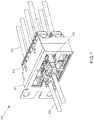
- FIG. 1 An exemplary embodiment of the present invention is illustrated in Fig. 1 , which shows a communication system 30, which includes a patch panel 32 with jacks 34 and corresponding RJ45 plugs 36. Respective cables 38 are terminated to plugs 36, and respective cables 40 are terminated to jacks 34. Once a plug 36 mates with a jack 34 data can flow in both directions through these connectors.
- the communication system 30 is illustrated in Fig. 1 as having a patch panel, alternative embodiments can include other active or passive equipment. Examples of passive equipment can be, but are not limited to, modular patch panels, punch-down patch panels, coupler patch panels, wall jacks, etc.
- Examples of active equipment can be, but are not limited to, Ethernet switches, routers, servers, physical layer management systems, and power-over-Ethernet equipment as can be found in data centers and or telecommunications rooms; security devices (cameras and other sensors, etc.) and door access equipment; and telephones, computers, fax machines, printers, and other peripherals as can be found in workstation areas.
- Communication system 30 can further include cabinets, racks, cable management and overhead routing systems, and other such equipment.
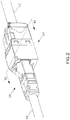
- Fig. 1 The jack and plug combination of Fig. 1 is also shown in Fig. 2 which illustrates the network jack 34 mated with the RJ45 plug 36. Note that in this figure, the orientation of the network jack 34 and the RJ45 plug 36 is rotated 180° about the central axis of cable 40 as compared to the orientation of Fig. 1 .
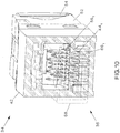
- Fig. 3 illustrates an exploded view of the network jack 34, which includes a front housing 42, plug interface contacts (PICs) 44, a printed circuit board (PCB) 46 (which in some embodiments may have crosstalk compensation components thereon), an insulation displacement contact (IDC) support 48, IDCs 50, a rear housing 52, and a wire cap 54.
- PICs plug interface contacts
- PCB printed circuit board
- IDC insulation displacement contact
- the PICs may be referred to as "back-rotated" which implies that the PICs are fixed at the (PCB) and generally flex about the location where each respective PIC connects to the PCB.
- Fig. 4 illustrates the assembled state of PICs 44 to PCB 46 of the network jack 34 with the front housing 42 removed for clarity.
- each PIC 44 corresponds to the RJ45 pin positions as defined by ANSI/TIA-568-C.2.
- a side view of Fig. 4 is depicted in Fig. 5 , and PICs 44 are illustrated individually in Fig. 6 .
- the outer PICs PICs 44 1 and 44 8 for a six-position plug, and PICs 44 1 , 44 2 , 44 7 , and 44 8 for a four-position plug
- PICs 44 3 , 44 4 , 44 5 , and 44 6 PICs 44 1 , 44 2 , 44 7 , and 44 8 for a four-position plug
- This can help provide proper future functionality by ensuring that sufficient normal force exists to mate with all corresponding plug contact 56 of an RJ45 plug (see Fig. 10 ).
- PIC 44 4 One way of achieving a desired distribution of mechanical stress is by varying the width of the PICs.
- An example of this is shown in PIC 44 4 , which has a pocket 60 4 which serves to assist in distributing stresses by varying the cross-sectional width of PIC 44 4 .
- the cross-section is varied by adding more material to PIC 44 4 as the distance is increased from the plug contact zone 58. This effectively causes the stiffness of PIC 44 4 to increase as distance is increased from the plug contact zone 58, resulting in a distribution of stresses over an increased portion of the deflection zone.
- PIC 44 4 is shown as an example, this varying cross-section is also applied to the remaining PICs 44 1 , 44 2 , 44 3 , 44 5 , 44 6 , 44 7 , and 44 8 .
- PICs 44 2 , 44 3 , and 44 7 vary their cross-sectional width by adjusting respective outer faces 62, while PICs 44 1 , 44 4 , 44 5 , 44 6 , and 44 8 vary their cross-sectional width with an internal pocket 60.
- PICs 44 vary their cross-sectional widths differently in order to control the relative amount of crosstalk as well as account for their full range of deflection. For example, PICs 44 1 , 44 2 , 44 7 , and 44 8 deflect more than PICs 44 3 , 44 4 , 44 5 , and 44 6 if a four position plug is inserted. Such a difference in deflection may cause the distance between PICs 44 2 and 44 3 , and 44 6 and 44 7 to become sufficiently small to cause a risk of an electrical short or a hipot failure. To reduce the potential of these risks, the cross sectional width of the PICs can be varied such that sufficient distance remains between adjacent PICs even in the event of varying levels of deflection. For example, referring to Fig.
- the PICs 44 employ different bend profiles. This can be seen in the side view of Fig. 5 .
- PICs 44 1 and 44 7 have a first bend profile
- PICs 44 3 and 44 5 have a second bend profile
- PICs 44 2 , 44 4 , 44 6 , and 44 8 have a third bend profile. Because PICs 44 1 and 44 7 may deflect more than PICs 44 3 and 44 5 in the event of mating with a four-position plug, PICs 44 1 and 44 7 have a longer deflection zone (than PICs 44 3 and 44 5 ) which may allow them to sustain additional deflection without plastic deformation.
- the capacitive and inductive coupling that occurs between signal line 3 and signal line 4 in the RJ45 plug 36 adds crosstalk between differential pair combinations 4:5 and 3:6.
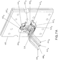
- the capacitive and inductive coupling that occurs between signal line 5 and signal line 6 also adds crosstalk between differential pair combinations 4:5 and 3:6. It is possible to reduce the negative effects of crosstalk via several ways. First, it is advantageous to reduce the initial amount of capacitive and inductive crosstalk coupling occurring between the 3:4 and 5:6 signal lines. This can be achieved by having PICs 44 3 and 44 5 bend down (relative to orientation shown in Fig. 7A ) and having PICs 44 4 and 44 6 bend up between the plug contact zone 58 and the PCB 46.
- FIG. 7B Another example of reducing the initial amount of crosstalk is illustrated in Fig. 7B where the network jack 34 (with front housing removed), is shown with PICs 44 having respective proximal ends 47 and distal ends 43.
- some proximal ends 47 e.g., corresponding to PICs 44 1 , 44 3 , 44 5 , and 44 7
- deflect more than other proximal ends 47 e.g., corresponding to PICs 44 2 , 44 4 , 44 6 , and 44 8 . Consequently electrical coupling between adjacent PICs 44 can be reduced in the vicinity of proximal ends 47.
- compensative capacitive coupling is required between signal lines 3 and 5, and signal lines 4 and 6, respectively.
- At least some of the desired compensative capacitive coupling can be achieved by placing PICs 44 4 and 44 5 within a near proximity of PICs 44 6 and 44 3 , respectively.
- a compliant pin 64 is used on PIC 44 1 to provide a mechanical retention as well as an electrical bond between the PIC 44 1 and the PCB 46.
- Compliant pin 64 has an "eye of the needle" shape, having an elongated oval slit, and is hemmed back upon itself to effectively double the material thickness as shown in the detail view of Fig. 8 .
- PIC 44 1 is fabricated from a sufficiently thin material to obtain the necessary deflection while not incurring plastic deformation. Hemming the compliant pin 64 may increase the strength of the hemmed region and provides a more robust interface to PCB 46.
- Fig. 8 illustrates only PIC 44 1 , the same compliant pin 64 may be used on any of the remaining PICs.
- FIG. 9 illustrates a rear isometric view of the front housing 42.
- Front combs 66 are integrated into the front housing 42 to control the relative spacing among PICs 44 and prevent PICs 44 from crossing, electrically shorting, and/or getting sufficiently close to one another where a hipot failure can occur.
- Front combs 66 are large enough to ensure that PICs 44 are combed during the entire state of deflection, including solid plug insertion if a four or six position plug is inserted.
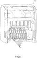
- Fig. 10 illustrates the deflection of the PICs 44 during normal operation via a front isometric partial section view of Fig. 2 .
- an exemplary RJ45 plug housing 68 is shown in dashed lines for clarity.
- plug contacts 56 interface with PICs 44 as shown.
- PICs 44 deflect downward within front combs 66 and create pressure at the interface between respective plug contacts 56 and PICs 44, resulting in an electrical bond sufficient for data to flow.
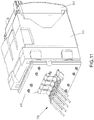
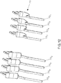
- FIG. 11 illustrates the alternate PICs 70 assembled to PCB 46
- Fig. 12 illustrates the alternate PICs 70 individually.
- PICs 70 do not contain pockets 60. Instead, at least in some cases, the cross-sectional width is varied by adjusting the overall width of the respective PICs as measured from one side to the other. The omission of pockets may simplify the manufacture of PICs 70 while still providing a similar effect of distributing bending stresses over the deflection zone and reducing plastic deformation.
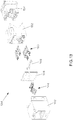
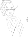
- FIG. 13 An example of a jack having PICs not forming part of the present invention is shown in Fig. 13 .
- This figure shows an exploded view of a jack 134, which includes a front housing 142, back-rotated PICs 144, a PCB 146 (which in some embodiments may have crosstalk compensation components thereon), an IDC support 148, IDCs 150, a rear housing 152, and a wire cap 154.
- the PICs 144 are comprised of four different types of PICs 160, 162, 162, and 164. These PICs 144 are attached to a PCB 146 via a top and bottom row. The top row includes PICs 162 and 166, and the bottom row includes PICs 160 and 164.
- PICs 160 and 162 include downward-facing concave loops 170 and 172, respectively, positioned near the point of attachment to the PCB (which is also the pivot point for the PICs when said PICs are deflected during mating). These loops 170 and 172 may increase the mechanical performance of the jack 134.
- PICs 160 interface plug contacts 2 and 8 PICs 162 interface plug contacts 1 and 7, PICs 164 interface with plug contacts 4 and 6, and PICs 166 interface plug contacts 3 and 5.
- PICs 160 and 162 make contact with the plug body and are subject to a higher degree of deformation than PICs 164 and 166 which mate with plug contacts 1, 2, 3 and 4.
- Loops 170 and 172 provide PICs 160 and 162 with an increased beam length, which helps accommodate the additional displacement and also helps provide the necessary normal force to potentially prevent at least some plastic deformation. Similar benefits can be realized during the insertion of a six-position plug which causes the outer-most PICs to undergo the greatest degree of deflection.
- PICs 164 and 166 are not expected to withstand the same degree deflection as PICs 160 and 162, their beams length can be shorter than the beam length of PICs 160 and 162.
- the shorter beam length may simplify the manufacturing process and may also improve the electrical performance of the jack 134 as it may help bring any crosstalk compensation components which may be present on the PCB 146 closer to the origin of any offending crosstalk.
Landscapes
- Details Of Connecting Devices For Male And Female Coupling (AREA)
- Coupling Device And Connection With Printed Circuit (AREA)
Applications Claiming Priority (3)
| Application Number | Priority Date | Filing Date | Title |
|---|---|---|---|
| US201361771600P | 2013-03-01 | 2013-03-01 | |
| US14/186,697 US9118134B2 (en) | 2013-03-01 | 2014-02-21 | RJ-45-compatible communication connector with contacts having wider distal ends |
| PCT/US2014/018052 WO2014133970A1 (en) | 2013-03-01 | 2014-02-24 | Communication connectors and systems |
Publications (2)
| Publication Number | Publication Date |
|---|---|
| EP2962367A1 EP2962367A1 (en) | 2016-01-06 |
| EP2962367B1 true EP2962367B1 (en) | 2020-04-08 |
Family
ID=51421147
Family Applications (1)
| Application Number | Title | Priority Date | Filing Date |
|---|---|---|---|
| EP14712069.5A Not-in-force EP2962367B1 (en) | 2013-03-01 | 2014-02-24 | Communication connector |
Country Status (4)
| Country | Link |
|---|---|
| US (2) | US9118134B2 (enExample) |
| EP (1) | EP2962367B1 (enExample) |
| JP (3) | JP6273300B2 (enExample) |
| WO (1) | WO2014133970A1 (enExample) |
Families Citing this family (15)
| Publication number | Priority date | Publication date | Assignee | Title |
|---|---|---|---|---|
| CN103579798B (zh) * | 2012-08-07 | 2016-08-03 | 泰科电子(上海)有限公司 | 电连接器及其导电端子组件 |
| US9118134B2 (en) * | 2013-03-01 | 2015-08-25 | Panduit Corp. | RJ-45-compatible communication connector with contacts having wider distal ends |
| USD759022S1 (en) * | 2013-03-13 | 2016-06-14 | Nagrastar Llc | Smart card interface |
| USD758372S1 (en) * | 2013-03-13 | 2016-06-07 | Nagrastar Llc | Smart card interface |
| TWM488118U (zh) * | 2014-03-19 | 2014-10-11 | Bing Xu Prec Co Ltd | 線纜連接器 |
| CN105406232B (zh) * | 2014-08-20 | 2018-02-02 | 富士康(昆山)电脑接插件有限公司 | Rj45插座连接器 |
| US9966703B2 (en) | 2014-10-17 | 2018-05-08 | Panduit Corp. | Communication connector |
| USD864968S1 (en) * | 2015-04-30 | 2019-10-29 | Echostar Technologies L.L.C. | Smart card interface |
| US10734765B2 (en) | 2016-10-31 | 2020-08-04 | Commscope Technologies Llc | Connector with capacitive crosstalk compensation |
| US10361514B2 (en) * | 2017-03-02 | 2019-07-23 | Panduit Corp. | Communication connectors utilizing multiple contact points |
| US10257919B1 (en) * | 2018-01-12 | 2019-04-09 | Jyh Eng Technology Co., Ltd. | Network socket device with compensation means |
| JP7139139B2 (ja) * | 2018-04-18 | 2022-09-20 | イリソ電子工業株式会社 | コネクタ |
| JP7136581B2 (ja) * | 2018-04-18 | 2022-09-13 | イリソ電子工業株式会社 | コネクタ |
| US11031738B1 (en) * | 2020-01-03 | 2021-06-08 | Jyh Eng Technology Co., Ltd. | Multiple socket panel device with anti-crosstalk shielding structure |
| KR102818147B1 (ko) * | 2021-03-04 | 2025-06-11 | 엘에스전선 주식회사 | 모듈러잭 |
Citations (1)
| Publication number | Priority date | Publication date | Assignee | Title |
|---|---|---|---|---|
| GB2417371A (en) * | 2002-10-21 | 2006-02-22 | Hubbell Inc | High performance electrical connector for telecommunications apparatus |
Family Cites Families (26)
| Publication number | Priority date | Publication date | Assignee | Title |
|---|---|---|---|---|
| US3824554A (en) * | 1972-08-28 | 1974-07-16 | G Shoholm | Spring-type press-fit |
| JPS541552Y2 (enExample) * | 1974-07-03 | 1979-01-24 | ||
| US4408824A (en) * | 1981-06-08 | 1983-10-11 | Amp Incorporated | Wire-in-slot terminal |
| JPS6025825Y2 (ja) * | 1981-07-21 | 1985-08-02 | 本多通信工業株式会社 | コネクタ |
| DE8317961U1 (de) * | 1982-07-01 | 1983-09-08 | AMP Inc., 17105 Harrisburg, Pa. | Kartenrandverbinder mit Einsetzkraft Null |
| US4691979A (en) * | 1983-08-04 | 1987-09-08 | Manda R & D | Compliant press-fit electrical contact |
| JPS6358776A (ja) * | 1986-08-27 | 1988-03-14 | アンプ インコ−ポレ−テツド | レセプタクルコンタクト |
| CH675929A5 (enExample) * | 1988-05-06 | 1990-11-15 | Cdm Connectors Dev & Mfg Ag | |
| JPH0458474A (ja) * | 1990-06-26 | 1992-02-25 | Witco Of Jupiter Dentsu Kk | 小型コネクタ用雌型接触子とその製造方法 |
| EP0677897A3 (de) * | 1994-04-14 | 1996-09-11 | Siemens Ag | Leiterplattenanordnung für Steckverbindungen. |
| FR2737941A1 (fr) * | 1995-08-18 | 1997-02-21 | Amp France | Assemblage de jack modulaire electrique |
| US5769647A (en) | 1995-11-22 | 1998-06-23 | The Siemon Company | Modular outlet employing a door assembly |
| US6106335A (en) * | 1998-06-05 | 2000-08-22 | Molex Incorporated | Crosstalk correction in electrical connectors |
| US6350158B1 (en) * | 2000-09-19 | 2002-02-26 | Avaya Technology Corp. | Low crosstalk communication connector |
| JP2004119253A (ja) * | 2002-09-27 | 2004-04-15 | Sumitomo Wiring Syst Ltd | 端子金具 |
| US6964587B2 (en) | 2002-11-10 | 2005-11-15 | Bel Fuse Ltd. | High performance, high capacitance gain, jack connector for data transmission or the like |
| JP4048102B2 (ja) * | 2002-11-19 | 2008-02-13 | ヒロセ電機株式会社 | モジュラージャック |
| US7252554B2 (en) * | 2004-03-12 | 2007-08-07 | Panduit Corp. | Methods and apparatus for reducing crosstalk in electrical connectors |
| US7628656B2 (en) * | 2006-03-10 | 2009-12-08 | Tyco Electronics Corporation | Receptacle with crosstalk optimizing contact array |
| WO2008076813A2 (en) * | 2006-12-13 | 2008-06-26 | Panduit Corp. | Communication jack having layered plug interface contacts |
| US20080254685A1 (en) | 2007-04-13 | 2008-10-16 | Tyco Electronics Corporation | Receptacle connector assembly for reducing EMI and/or crosstalk |
| FR2934425B1 (fr) | 2008-07-28 | 2021-07-30 | Legrand France | Insert et procede d'assemblage d'un tel insert. |
| US7708603B1 (en) | 2009-01-12 | 2010-05-04 | Hon Hai Precision Ind. Co., Ltd. | Electrical connector with improved crosstalk features |
| JP4795444B2 (ja) * | 2009-02-09 | 2011-10-19 | ホシデン株式会社 | コネクタ |
| US7850492B1 (en) * | 2009-11-03 | 2010-12-14 | Panduit Corp. | Communication connector with improved crosstalk compensation |
| US9118134B2 (en) * | 2013-03-01 | 2015-08-25 | Panduit Corp. | RJ-45-compatible communication connector with contacts having wider distal ends |
-
2014
- 2014-02-21 US US14/186,697 patent/US9118134B2/en not_active Expired - Fee Related
- 2014-02-24 WO PCT/US2014/018052 patent/WO2014133970A1/en not_active Ceased
- 2014-02-24 EP EP14712069.5A patent/EP2962367B1/en not_active Not-in-force
- 2014-02-24 JP JP2015560239A patent/JP6273300B2/ja not_active Expired - Fee Related
-
2015
- 2015-07-17 US US14/802,123 patent/US9455517B2/en not_active Expired - Fee Related
-
2017
- 2017-06-28 JP JP2017125963A patent/JP6403840B2/ja not_active Expired - Fee Related
-
2018
- 2018-07-17 JP JP2018133965A patent/JP6633144B2/ja not_active Expired - Fee Related
Patent Citations (1)
| Publication number | Priority date | Publication date | Assignee | Title |
|---|---|---|---|---|
| GB2417371A (en) * | 2002-10-21 | 2006-02-22 | Hubbell Inc | High performance electrical connector for telecommunications apparatus |
Also Published As
| Publication number | Publication date |
|---|---|
| US9118134B2 (en) | 2015-08-25 |
| JP6403840B2 (ja) | 2018-10-10 |
| US20140248807A1 (en) | 2014-09-04 |
| JP6273300B2 (ja) | 2018-01-31 |
| JP2017168461A (ja) | 2017-09-21 |
| JP2016511514A (ja) | 2016-04-14 |
| US9455517B2 (en) | 2016-09-27 |
| JP2018160474A (ja) | 2018-10-11 |
| WO2014133970A1 (en) | 2014-09-04 |
| EP2962367A1 (en) | 2016-01-06 |
| JP6633144B2 (ja) | 2020-01-22 |
| US20150325965A1 (en) | 2015-11-12 |
Similar Documents
| Publication | Publication Date | Title |
|---|---|---|
| EP2962367B1 (en) | Communication connector | |
| CA2686911C (en) | Electrical connector with separate contact mounting and compensation boards | |
| US7985101B2 (en) | RJ-45 style communications jacks that are configured to receive both RJ-45 and RJ-11 style communications plugs | |
| CN102790306B (zh) | 电连接器 | |
| US20090298341A1 (en) | Communications Connectors with Jackwire Contacts and Printed Circuit Boards | |
| US10153592B2 (en) | Communications connectors | |
| US9601886B1 (en) | Communication plugs and components thereof | |
| EP2522055B1 (en) | A modular connector for a cable-less patching device | |
| US7670194B1 (en) | RJ-45 style communications jacks having mechanisms that prevent an RJ-11 style communications plug from being fully inserted within the jack | |
| EP2973883B1 (en) | Communication jack | |
| US6450838B2 (en) | Universally configurable modular connector | |
| EP2624377B1 (en) | Communication adapter | |
| JP7282522B2 (ja) | プラグインタフェース接点間に誘電体膜を有する通信ジャック | |
| US9281622B2 (en) | Communications jacks having low-coupling contacts | |
| GB2322976A (en) | Data communications connectors |
Legal Events
| Date | Code | Title | Description |
|---|---|---|---|
| PUAI | Public reference made under article 153(3) epc to a published international application that has entered the european phase |
Free format text: ORIGINAL CODE: 0009012 |
|
| 17P | Request for examination filed |
Effective date: 20150928 |
|
| AK | Designated contracting states |
Kind code of ref document: A1 Designated state(s): AL AT BE BG CH CY CZ DE DK EE ES FI FR GB GR HR HU IE IS IT LI LT LU LV MC MK MT NL NO PL PT RO RS SE SI SK SM TR |
|
| AX | Request for extension of the european patent |
Extension state: BA ME |
|
| DAX | Request for extension of the european patent (deleted) | ||
| STAA | Information on the status of an ep patent application or granted ep patent |
Free format text: STATUS: REQUEST FOR EXAMINATION WAS MADE |
|
| STAA | Information on the status of an ep patent application or granted ep patent |
Free format text: STATUS: EXAMINATION IS IN PROGRESS |
|
| 17Q | First examination report despatched |
Effective date: 20190222 |
|
| GRAP | Despatch of communication of intention to grant a patent |
Free format text: ORIGINAL CODE: EPIDOSNIGR1 |
|
| STAA | Information on the status of an ep patent application or granted ep patent |
Free format text: STATUS: GRANT OF PATENT IS INTENDED |
|
| RIC1 | Information provided on ipc code assigned before grant |
Ipc: H01R 24/00 20110101AFI20190930BHEP |
|
| RIC1 | Information provided on ipc code assigned before grant |
Ipc: H01R 27/00 20060101ALI20191004BHEP Ipc: H01R 24/00 20110101ALI20191004BHEP Ipc: H01R 24/64 20110101ALI20191004BHEP Ipc: H01R 13/6474 20110101ALI20191004BHEP Ipc: H01R 13/6461 20110101AFI20191004BHEP |
|
| INTG | Intention to grant announced |
Effective date: 20191021 |
|
| GRAS | Grant fee paid |
Free format text: ORIGINAL CODE: EPIDOSNIGR3 |
|
| GRAA | (expected) grant |
Free format text: ORIGINAL CODE: 0009210 |
|
| STAA | Information on the status of an ep patent application or granted ep patent |
Free format text: STATUS: THE PATENT HAS BEEN GRANTED |
|
| AK | Designated contracting states |
Kind code of ref document: B1 Designated state(s): AL AT BE BG CH CY CZ DE DK EE ES FI FR GB GR HR HU IE IS IT LI LT LU LV MC MK MT NL NO PL PT RO RS SE SI SK SM TR |
|
| REG | Reference to a national code |
Ref country code: AT Ref legal event code: REF Ref document number: 1255617 Country of ref document: AT Kind code of ref document: T Effective date: 20200415 Ref country code: CH Ref legal event code: EP |
|
| REG | Reference to a national code |
Ref country code: IE Ref legal event code: FG4D |
|
| REG | Reference to a national code |
Ref country code: DE Ref legal event code: R096 Ref document number: 602014063468 Country of ref document: DE |
|
| REG | Reference to a national code |
Ref country code: NL Ref legal event code: MP Effective date: 20200408 |
|
| REG | Reference to a national code |
Ref country code: LT Ref legal event code: MG4D |
|
| PG25 | Lapsed in a contracting state [announced via postgrant information from national office to epo] |
Ref country code: FI Free format text: LAPSE BECAUSE OF FAILURE TO SUBMIT A TRANSLATION OF THE DESCRIPTION OR TO PAY THE FEE WITHIN THE PRESCRIBED TIME-LIMIT Effective date: 20200408 Ref country code: NO Free format text: LAPSE BECAUSE OF FAILURE TO SUBMIT A TRANSLATION OF THE DESCRIPTION OR TO PAY THE FEE WITHIN THE PRESCRIBED TIME-LIMIT Effective date: 20200708 Ref country code: SE Free format text: LAPSE BECAUSE OF FAILURE TO SUBMIT A TRANSLATION OF THE DESCRIPTION OR TO PAY THE FEE WITHIN THE PRESCRIBED TIME-LIMIT Effective date: 20200408 Ref country code: GR Free format text: LAPSE BECAUSE OF FAILURE TO SUBMIT A TRANSLATION OF THE DESCRIPTION OR TO PAY THE FEE WITHIN THE PRESCRIBED TIME-LIMIT Effective date: 20200709 Ref country code: LT Free format text: LAPSE BECAUSE OF FAILURE TO SUBMIT A TRANSLATION OF THE DESCRIPTION OR TO PAY THE FEE WITHIN THE PRESCRIBED TIME-LIMIT Effective date: 20200408 Ref country code: NL Free format text: LAPSE BECAUSE OF FAILURE TO SUBMIT A TRANSLATION OF THE DESCRIPTION OR TO PAY THE FEE WITHIN THE PRESCRIBED TIME-LIMIT Effective date: 20200408 Ref country code: PT Free format text: LAPSE BECAUSE OF FAILURE TO SUBMIT A TRANSLATION OF THE DESCRIPTION OR TO PAY THE FEE WITHIN THE PRESCRIBED TIME-LIMIT Effective date: 20200817 Ref country code: IS Free format text: LAPSE BECAUSE OF FAILURE TO SUBMIT A TRANSLATION OF THE DESCRIPTION OR TO PAY THE FEE WITHIN THE PRESCRIBED TIME-LIMIT Effective date: 20200808 |
|
| REG | Reference to a national code |
Ref country code: AT Ref legal event code: MK05 Ref document number: 1255617 Country of ref document: AT Kind code of ref document: T Effective date: 20200408 |
|
| PG25 | Lapsed in a contracting state [announced via postgrant information from national office to epo] |
Ref country code: BG Free format text: LAPSE BECAUSE OF FAILURE TO SUBMIT A TRANSLATION OF THE DESCRIPTION OR TO PAY THE FEE WITHIN THE PRESCRIBED TIME-LIMIT Effective date: 20200708 Ref country code: LV Free format text: LAPSE BECAUSE OF FAILURE TO SUBMIT A TRANSLATION OF THE DESCRIPTION OR TO PAY THE FEE WITHIN THE PRESCRIBED TIME-LIMIT Effective date: 20200408 Ref country code: HR Free format text: LAPSE BECAUSE OF FAILURE TO SUBMIT A TRANSLATION OF THE DESCRIPTION OR TO PAY THE FEE WITHIN THE PRESCRIBED TIME-LIMIT Effective date: 20200408 Ref country code: RS Free format text: LAPSE BECAUSE OF FAILURE TO SUBMIT A TRANSLATION OF THE DESCRIPTION OR TO PAY THE FEE WITHIN THE PRESCRIBED TIME-LIMIT Effective date: 20200408 |
|
| PG25 | Lapsed in a contracting state [announced via postgrant information from national office to epo] |
Ref country code: AL Free format text: LAPSE BECAUSE OF FAILURE TO SUBMIT A TRANSLATION OF THE DESCRIPTION OR TO PAY THE FEE WITHIN THE PRESCRIBED TIME-LIMIT Effective date: 20200408 |
|
| REG | Reference to a national code |
Ref country code: DE Ref legal event code: R097 Ref document number: 602014063468 Country of ref document: DE |
|
| PG25 | Lapsed in a contracting state [announced via postgrant information from national office to epo] |
Ref country code: IT Free format text: LAPSE BECAUSE OF FAILURE TO SUBMIT A TRANSLATION OF THE DESCRIPTION OR TO PAY THE FEE WITHIN THE PRESCRIBED TIME-LIMIT Effective date: 20200408 Ref country code: DK Free format text: LAPSE BECAUSE OF FAILURE TO SUBMIT A TRANSLATION OF THE DESCRIPTION OR TO PAY THE FEE WITHIN THE PRESCRIBED TIME-LIMIT Effective date: 20200408 Ref country code: AT Free format text: LAPSE BECAUSE OF FAILURE TO SUBMIT A TRANSLATION OF THE DESCRIPTION OR TO PAY THE FEE WITHIN THE PRESCRIBED TIME-LIMIT Effective date: 20200408 Ref country code: RO Free format text: LAPSE BECAUSE OF FAILURE TO SUBMIT A TRANSLATION OF THE DESCRIPTION OR TO PAY THE FEE WITHIN THE PRESCRIBED TIME-LIMIT Effective date: 20200408 Ref country code: CZ Free format text: LAPSE BECAUSE OF FAILURE TO SUBMIT A TRANSLATION OF THE DESCRIPTION OR TO PAY THE FEE WITHIN THE PRESCRIBED TIME-LIMIT Effective date: 20200408 Ref country code: ES Free format text: LAPSE BECAUSE OF FAILURE TO SUBMIT A TRANSLATION OF THE DESCRIPTION OR TO PAY THE FEE WITHIN THE PRESCRIBED TIME-LIMIT Effective date: 20200408 Ref country code: EE Free format text: LAPSE BECAUSE OF FAILURE TO SUBMIT A TRANSLATION OF THE DESCRIPTION OR TO PAY THE FEE WITHIN THE PRESCRIBED TIME-LIMIT Effective date: 20200408 Ref country code: SM Free format text: LAPSE BECAUSE OF FAILURE TO SUBMIT A TRANSLATION OF THE DESCRIPTION OR TO PAY THE FEE WITHIN THE PRESCRIBED TIME-LIMIT Effective date: 20200408 |
|
| PLBE | No opposition filed within time limit |
Free format text: ORIGINAL CODE: 0009261 |
|
| STAA | Information on the status of an ep patent application or granted ep patent |
Free format text: STATUS: NO OPPOSITION FILED WITHIN TIME LIMIT |
|
| PG25 | Lapsed in a contracting state [announced via postgrant information from national office to epo] |
Ref country code: SK Free format text: LAPSE BECAUSE OF FAILURE TO SUBMIT A TRANSLATION OF THE DESCRIPTION OR TO PAY THE FEE WITHIN THE PRESCRIBED TIME-LIMIT Effective date: 20200408 Ref country code: PL Free format text: LAPSE BECAUSE OF FAILURE TO SUBMIT A TRANSLATION OF THE DESCRIPTION OR TO PAY THE FEE WITHIN THE PRESCRIBED TIME-LIMIT Effective date: 20200408 |
|
| 26N | No opposition filed |
Effective date: 20210112 |
|
| PG25 | Lapsed in a contracting state [announced via postgrant information from national office to epo] |
Ref country code: SI Free format text: LAPSE BECAUSE OF FAILURE TO SUBMIT A TRANSLATION OF THE DESCRIPTION OR TO PAY THE FEE WITHIN THE PRESCRIBED TIME-LIMIT Effective date: 20200408 |
|
| REG | Reference to a national code |
Ref country code: DE Ref legal event code: R119 Ref document number: 602014063468 Country of ref document: DE |
|
| PG25 | Lapsed in a contracting state [announced via postgrant information from national office to epo] |
Ref country code: MC Free format text: LAPSE BECAUSE OF FAILURE TO SUBMIT A TRANSLATION OF THE DESCRIPTION OR TO PAY THE FEE WITHIN THE PRESCRIBED TIME-LIMIT Effective date: 20200408 |
|
| GBPC | Gb: european patent ceased through non-payment of renewal fee |
Effective date: 20210224 |
|
| REG | Reference to a national code |
Ref country code: BE Ref legal event code: MM Effective date: 20210228 |
|
| PG25 | Lapsed in a contracting state [announced via postgrant information from national office to epo] |
Ref country code: LU Free format text: LAPSE BECAUSE OF NON-PAYMENT OF DUE FEES Effective date: 20210224 Ref country code: LI Free format text: LAPSE BECAUSE OF NON-PAYMENT OF DUE FEES Effective date: 20210228 Ref country code: CH Free format text: LAPSE BECAUSE OF NON-PAYMENT OF DUE FEES Effective date: 20210228 |
|
| PG25 | Lapsed in a contracting state [announced via postgrant information from national office to epo] |
Ref country code: GB Free format text: LAPSE BECAUSE OF NON-PAYMENT OF DUE FEES Effective date: 20210224 Ref country code: FR Free format text: LAPSE BECAUSE OF NON-PAYMENT OF DUE FEES Effective date: 20210228 Ref country code: IE Free format text: LAPSE BECAUSE OF NON-PAYMENT OF DUE FEES Effective date: 20210224 Ref country code: DE Free format text: LAPSE BECAUSE OF NON-PAYMENT OF DUE FEES Effective date: 20210901 |
|
| PG25 | Lapsed in a contracting state [announced via postgrant information from national office to epo] |
Ref country code: BE Free format text: LAPSE BECAUSE OF NON-PAYMENT OF DUE FEES Effective date: 20210228 |
|
| PG25 | Lapsed in a contracting state [announced via postgrant information from national office to epo] |
Ref country code: HU Free format text: LAPSE BECAUSE OF FAILURE TO SUBMIT A TRANSLATION OF THE DESCRIPTION OR TO PAY THE FEE WITHIN THE PRESCRIBED TIME-LIMIT; INVALID AB INITIO Effective date: 20140224 |
|
| PG25 | Lapsed in a contracting state [announced via postgrant information from national office to epo] |
Ref country code: CY Free format text: LAPSE BECAUSE OF FAILURE TO SUBMIT A TRANSLATION OF THE DESCRIPTION OR TO PAY THE FEE WITHIN THE PRESCRIBED TIME-LIMIT Effective date: 20200408 |
|
| PG25 | Lapsed in a contracting state [announced via postgrant information from national office to epo] |
Ref country code: MK Free format text: LAPSE BECAUSE OF FAILURE TO SUBMIT A TRANSLATION OF THE DESCRIPTION OR TO PAY THE FEE WITHIN THE PRESCRIBED TIME-LIMIT Effective date: 20200408 |
|
| PG25 | Lapsed in a contracting state [announced via postgrant information from national office to epo] |
Ref country code: MT Free format text: LAPSE BECAUSE OF FAILURE TO SUBMIT A TRANSLATION OF THE DESCRIPTION OR TO PAY THE FEE WITHIN THE PRESCRIBED TIME-LIMIT Effective date: 20200408 |
|
| PG25 | Lapsed in a contracting state [announced via postgrant information from national office to epo] |
Ref country code: TR Free format text: LAPSE BECAUSE OF FAILURE TO SUBMIT A TRANSLATION OF THE DESCRIPTION OR TO PAY THE FEE WITHIN THE PRESCRIBED TIME-LIMIT Effective date: 20200408 |