EP2961640B1 - Gurtaufroller mit einer elektromotorischen wickelhilfe und verfahren zur ansteuerung einer elektromotorischen wickelhilfe für einen gurtaufroller - Google Patents
Gurtaufroller mit einer elektromotorischen wickelhilfe und verfahren zur ansteuerung einer elektromotorischen wickelhilfe für einen gurtaufroller Download PDFInfo
- Publication number
- EP2961640B1 EP2961640B1 EP14706577.5A EP14706577A EP2961640B1 EP 2961640 B1 EP2961640 B1 EP 2961640B1 EP 14706577 A EP14706577 A EP 14706577A EP 2961640 B1 EP2961640 B1 EP 2961640B1
- Authority
- EP
- European Patent Office
- Prior art keywords
- belt
- winding aid
- electromotive
- belt retractor
- aid
- Prior art date
- Legal status (The legal status is an assumption and is not a legal conclusion. Google has not performed a legal analysis and makes no representation as to the accuracy of the status listed.)
- Active
Links
Images

Classifications
-
- B—PERFORMING OPERATIONS; TRANSPORTING
- B60—VEHICLES IN GENERAL
- B60R—VEHICLES, VEHICLE FITTINGS, OR VEHICLE PARTS, NOT OTHERWISE PROVIDED FOR
- B60R22/00—Safety belts or body harnesses in vehicles
- B60R22/34—Belt retractors, e.g. reels
- B60R22/46—Reels with means to tension the belt in an emergency by forced winding up
-
- B—PERFORMING OPERATIONS; TRANSPORTING
- B60—VEHICLES IN GENERAL
- B60R—VEHICLES, VEHICLE FITTINGS, OR VEHICLE PARTS, NOT OTHERWISE PROVIDED FOR
- B60R22/00—Safety belts or body harnesses in vehicles
- B60R22/34—Belt retractors, e.g. reels
-
- B—PERFORMING OPERATIONS; TRANSPORTING
- B60—VEHICLES IN GENERAL
- B60R—VEHICLES, VEHICLE FITTINGS, OR VEHICLE PARTS, NOT OTHERWISE PROVIDED FOR
- B60R22/00—Safety belts or body harnesses in vehicles
- B60R22/34—Belt retractors, e.g. reels
- B60R22/44—Belt retractors, e.g. reels with means for reducing belt tension during use under normal conditions
- B60R2022/4446—Belt retractors, e.g. reels with means for reducing belt tension during use under normal conditions using one spring and one additional retraction device in series
-
- B—PERFORMING OPERATIONS; TRANSPORTING
- B60—VEHICLES IN GENERAL
- B60R—VEHICLES, VEHICLE FITTINGS, OR VEHICLE PARTS, NOT OTHERWISE PROVIDED FOR
- B60R22/00—Safety belts or body harnesses in vehicles
- B60R22/34—Belt retractors, e.g. reels
- B60R22/46—Reels with means to tension the belt in an emergency by forced winding up
- B60R2022/4666—Reels with means to tension the belt in an emergency by forced winding up characterised by electric actuators
Definitions
- the invention relates to a belt retractor with an electromotive winding aid having the features of the preamble of claim 1 and a method for controlling an electromotive winding aid for a belt retractor having the features of the preamble of claim 5.
- Belt retractors with electromotive drives are known, in particular, as reversible belt tensioners, which, when activated in a pre-accident phase, pull out belt slack from a seat belt of a seat belt device.
- a return spring is further provided, which exerts a retraction force on the seat belt, independently of the action of the electromotive winding aid.
- This retraction force should be as low as possible for reasons of comfort in the applied state of the seat belt, while still ensuring that the seat belt is reliably wound during storage in the parking position.
- the return springs are basically subject to aging processes, so that the retraction force of the return springs decreases with increasing life and the consequent high number of use cycles.
- the object of the invention is to provide a belt retractor with an electric motor winding aid, which has an increased ease of use and allows winding the seat belt in the parking position even after a high number of use cycles regardless of the retraction force of the return spring. It is another object of the invention to provide a method for controlling an electric motor winding aid of a belt retractor, which allows an improved winding of the webbing in the parking position.
- a memory unit in which various control profiles are stored, and the electromotive winding aid depending on the exceeding of predetermined use cycles of the belt retractor and / or the sensed ambient temperature according to different control profiles can be controlled. It has been found that the retraction force of the return spring decreases with increasing number of use cycles due to aging and is also dependent on the ambient temperature. To compensate for these changes in the retraction force different control profiles are stored in the memory unit, which then serve in a sensing of the corresponding parameters for controlling the winding aid. These drive profiles can z. B. different withdrawal forces or courses of the retraction force, so that the entire retraction force from the retraction force of the return spring and the winding aid is then constant regardless of the aging of the return spring and the ambient temperature or corresponds to a predetermined course.
- the electromotive winding aid can be controlled as a function of the current consumption of the winding aid.
- the current consumption of the winding aid increases above a predetermined limit. In this case, the winding aid is then deactivated for its own protection.
- the electromotive winding aid is additionally controllable in dependence on the plug state of a belt tongue lockable in a buckle. Due to the plug-in state of the belt tongue, the on and off of the seat belt can be reliably detected. Furthermore, it can be concluded in each case by a changing plug state of the belt tongue on a use cycle, which in the sum allow an indirect conclusion on the aging state of the return spring.
- the belt retractor has a belt spring biasing return spring, which has a retraction force of less than 1 N.
- the proposed low retraction force allows a very comfortable fit of the seat belt for the occupant, the low retraction force is then increased by the support of the winding aid for Wegparken of the webbing to a higher retraction force and the webbing is wound safely into the parking position.
- a stored seat belt Due to the non-locked belt tongue, a stored seat belt can be detected in a first step. If the Gurtbandeinzugs Republic then does not exceed the predetermined limit, it can be concluded that the retraction force of the return spring is not sufficient to wind the webbing in the park position. In this case, the winding aid is then activated and the webbing safely wound by the support of the winding aid.
- the electromotive winding aid is deactivated when the sensor device for sensing the Gurtbandeinzugs biology senses a lying below a predetermined limit Gurtbandeinzugs economically and / or the power consumption of the electric motor winding aid exceeds a predetermined limit.
- the predetermined limit of Gurtbandeinzugs economically can be sensed, for example, the achievement of the parking position, since the Gurtbandeinzugs economically in the parking position is equal to zero and shortly before reaching the parking position drops very much and thereby falls below the predetermined limit.
- the winding aid is also deactivated when the occupant holds the seat belt, for example, and the current consumption of the winding aid thereby exceeds a predetermined limit.
- a sensor device for sensing parameters which characterize the aging state of a return spring biasing a belt shaft of the belt retractor, and the electromotive winding aid is actuated according to the aging state of the return spring according to different control profiles
- the sensor device may be, for example, a buckle sensor, the plug-in operations of which are counted in an evaluation unit.
- the sensor device can also be a position sensor directed at the return spring itself, which senses the position of the return spring.
- this decreasing retraction force is then compensated by the control of the winding aid by means of an individually provided for this case An horrprofils.
- This drive profile can be increased by a constant factor Retraction force of the winding aid or be formed by a modified characteristic with an individually adapted course of the retraction force exerted by the winding aid.
- a sensor device be provided for sensing the ambient temperature, and the electromotive winding aid is controlled in dependence on the ambient temperature according to different control profiles. Due to the ambient temperature, the retraction force of the return spring can also vary regardless of their aging state. This change in the retraction force can then be compensated by a corresponding support of the return movement by the winding aid so far that the webbing is wound safely again with a predetermined minimum retraction force.
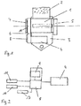
- Fig. 1 is a belt retractor with a rotatably mounted in a frame 3 two-piece belt shaft 1 to recognize with a force limiting device arranged between the two parts.
- a belt 2 of a seat belt device is wound, while the other part of the belt shaft 1 by driving a vehicle-sensitive and / or belt-sensitive controllable blocking device in the frame 3 is vehicle-locked, so that the belt shaft body with the wound webbing. 2 can then turn only by an activation of the force limiting device in Gurtbandauszugsraum.
- the two-part belt shaft 1 is further spring-biased via a spring held in a spring cassette 7 return spring 12 in the winding, which is designed as a very weak return spring 12 with a retracting force of 0.5 to 1.0 N.
- the seat belt device further comprises a belt tongue slidably guided on the belt webbing 2, a belt buckle fastened to the vehicle, a vehicle-fixed end fitting for fastening the free end of the belt strap to the vehicle structure and, if appropriate, a deflector fastened to the vehicle.
- the above items of the seat belt device are not darg Robinson, but can be thought out as known in the art.
- an electromotive winding aid 4 in the form of an electric motor is provided on the frame 3 of the belt retractor, which can be coupled via a gear 6 to the belt shaft 1.
- a control device 8 is provided for controlling the winding aid 4, which, as in the Fig. 2 can be seen, signaling technology with a sensor device 11 for detecting the locking state BS of the belt tongue in the Belt lock, a sensor device 10 for sensing the Gurtbandeinzugs Anthony BRS and a sensor device 13 for sensing the ambient temperature connected.
- the sensor device 10 for sensing the Gurtbandeinzugs Anlagen BRS can be formed for example by a non-rotatably connected to the Gurtwellenanalysis magnetic wheel with a plurality of individual magnets with a different orientation and a directed to the magnetic wheel Hall sensor.
- a memory unit 9 is further provided, in which various control profiles are stored.
- the control profiles may include individual control data for the electromotive winding aid 4 for generating different retraction forces acting in the winding direction of the belt shaft 1. In this case, both the height and the course of the withdrawal forces in the different control profiles can be different.
- the control profiles can also be designed for different return springs 12 with different retraction forces, so that the winding aid 4 can also be used for belt retractors with different return springs 12.
- the electromotive winding aid 4 is preferably coupled directly to the belt shaft 1 or to the inner end of the return spring 12, so that the return spring 12 and the winding aid 4 act in parallel on the belt shaft 1.
- the withdrawal forces exerted by the return spring 12 and the winding aid 4 on the belt shaft 1, and it is still a slight force acting on the webbing 2 retraction force is also available in case of failure of the winding aid 4 or the return spring 12.
- FIG. 3 and FIG. 4 the control logic of the method according to the invention in the control device 8 for activating and deactivating the winding aid 4 is shown.
- the activation of the winding aid 4 is shown as the result ESTART. If one of the criteria is not met, the webbing is pulled in by the return spring 12 alone. This result of the query is labeled BP.
- the winding aid 4 is deactivated when the current consumption IM of the winding aid exceeds a predetermined first limit value Y or the Gurtbandeinzugs Eck BRS falls below a predetermined second limit value X2.
- the winding aid 4 is not activated, and the activated state of the winding aid 4 is not changed, so that the webbing is further rolled up with the help of the winding aid 4 in the park position. This condition is identified as BP.
- the winding aid 4 is deactivated. This deactivation is in the Fig. 4 marked with the result ESTOP.
Landscapes
- Engineering & Computer Science (AREA)
- Mechanical Engineering (AREA)
- Automotive Seat Belt Assembly (AREA)
Description
- Die Erfindung betrifft einen Gurtaufroller mit einer elektromotorischen Wickelhilfe mit den Merkmalen des Oberbegriffs von Anspruch 1 und ein Verfahren zur Ansteuerung einer elektromotorischen Wickelhilfe für einen Gurtaufroller mit den Merkmalen des Oberbegriffs von Anspruch 5.
- Gurtaufroller mit elektromotorischen Antrieben sind insbesondere als reversible Gurtstraffer bekannt, welche bei einer Aktivierung in einer Vor-Unfallphase vorhandene Gurtlose aus einem Sicherheitsgurt einer Sicherheitsgurteinrichtung herausziehen.
- Aus der
DE 43 32 205 C2 ist es darüber hinaus auch bekannt, den elektromotorischen Antrieb auch zur Rückholung des Sicherheitsgurtes in die Parkposition zu verwenden. Der elektromotorische Antrieb wird dabei in Abhängigkeit von dem Steckzustand der Gurtzunge angesteuert. - In dem Gurtaufroller ist ferner eine Rückholfeder vorgesehen, welche unabhängig von dem Wirken der elektromotorischen Wickelhilfe eine Rückzugskraft auf den Sicherheitsgurt ausübt. Diese Rückzugskraft sollte aus Komfortgründen im angelegten Zustand des Sicherheitsgurtes möglichst gering sein, wobei trotzdem sichergestellt sein muss, dass der Sicherheitsgurt beim Ablegen zuverlässig in die Parkposition aufgewickelt wird.
- Ferner unterliegen die Rückholfedern grundsätzlich Alterungsprozessen, so dass die Rückzugskraft der Rückholfedern mit zunehmender Lebensdauer und der dadurch bedingten hohen Anzahl von Benutzungszyklen abnimmt.
- Aus der Druckschrift
US 2002/189880 A1 ist es bekannt, den Gurtaufroller mit einem Elektromotor zu versehen, welcher als elektromotorische Wickelhilfe aktiviert wird, wenn die Aufwickelgeschwindigkeit des Sicherheitsgurtes bedingt durch die Alterung der Wickelfeder einen vorbestimmten Wert unterschreitet. - Aufgabe der Erfindung ist es, einen Gurtaufroller mit einer elektromotorischen Wickelhilfe zu schaffen, welcher einen erhöhten Benutzungskomfort aufweist und ein Aufwickeln des Sicherheitsgurtes in die Parkposition auch noch nach einer hohen Anzahl von Benutzungszyklen unabhängig von der Rückzugskraft der Rückholfeder ermöglicht. Ferner ist es Aufgabe der Erfindung, ein Verfahren zur Ansteuerung einer elektromotorischen Wickelhilfe eines Gurtaufrollers zu schaffen, welches ein verbessertes Aufwickeln des Gurtbandes in die Parkposition ermöglicht.
- Zur Lösung der Aufgabe wird erfindungsgemäß ein Gurtaufroller mit den Merkmalen des Anspruchs 1 und ein Verfahren mit den Merkmalen des Anspruchs 5 vorgeschlagen. Weitere bevorzugte Ausführungsformen der Erfindung sind den Unteransprüchen, den Figuren und der zugehörigen Beschreibung zu entnehmen.
- Gemäß dem Grundgedanken der Erfindung wird vorgeschlagen, dass eine Speichereinheit vorgesehen ist, in welcher verschiedene Ansteuerprofile abgelegt sind, und die elektromotorische Wickelhilfe in Abhängigkeit von dem Überschreiten vorgegebener Benutzungszyklen des Gurtaufrollers und/oder der sensierten Umgebungstemperatur nach unterschiedlichen Ansteuerprofilen ansteuerbar ist. Es hat sich herausgestellt, dass die Rückzugskraft der Rückholfeder mit steigender Anzahl der Benutzungszyklen aufgrund von Alterung sinkt und außerdem von der Umgebungstemperatur abhängig ist. Zur Kompensation dieser Veränderungen der Rückzugskraft sind in der Speichereinheit verschiedene Ansteuerprofile abgelegt, welche dann bei einer Sensierung der entsprechenden Kenngrößen zur Ansteuerung der Wickelhilfe dienen. Diese Ansteuerprofile können z. B. verschiedene Rückzugskräfte oder auch Verläufe der Rückzugskraft umfassen, so dass die gesamte Rückzugskraft aus der Rückzugskraft der Rückholfeder und der Wickelhilfe dann unabhängig von der Alterung der Rückholfeder und der Umgebungstemperatur konstant ist oder einem vorgegebenen Verlauf entspricht.
- Ferner wird vorgeschlagen, dass die elektromotorische Wickelhilfe in Abhängigkeit von der Stromaufnahme der Wickelhilfe ansteuerbar ist. Für den Fall, dass der Insasse das Gurtband z.B. festhält und die Aufwickelbewegung dadurch aktiv verhindert wird, steigt die Stromaufnahme der Wickelhilfe über einen vorgegebenen Grenzwert an. In diesem Fall wird die Wickelhilfe dann zu ihrem eigenen Schutz deaktiviert.
- Gemäß einer weiteren bevorzugten Ausführungsform der Erfindung wird vorgeschlagen, dass die elektromotorische Wickelhilfe zusätzlich in Abhängigkeit von dem Steckzustand einer in einem Gurtschloss verriegelbaren Gurtzunge ansteuerbar ist. Durch den Steckzustand der Gurtzunge kann das An- und Ablegen des Sicherheitsgurtes sicher erkannt werden. Ferner kann durch einen sich verändernden Steckzustand der Gurtzunge jeweils auf einen Benutzungszyklus geschlossen werden, welche in der Summe einen mittelbaren Rückschluss auf den Alterungszustand der Rückholfeder ermöglichen.
- Ferner wird vorgeschlagen, dass der Gurtaufroller eine die Gurtwelle in Aufwickelrichtung vorspannende Rückholfeder aufweist, welche eine Rückzugskraft von weniger als 1 N aufweist. Die vorgeschlagene geringe Rückzugskraft ermöglicht einen sehr angenehmen Tragekomfort des Sicherheitsgurtes für den Insassen, wobei die geringe Rückzugskraft dann durch die Unterstützung durch die Wickelhilfe zum Wegparken des Gurtbandes auf eine höhere Rückzugskraft erhöht wird und das Gurtband sicher in die Parkposition aufgewickelt wird.
- Weiter wird zur Lösung der Aufgabe ein Verfahren zur Ansteuerung einer elektromotorischen Wickelhilfe eines Gurtaufrollers vorgeschlagen, bei dem die elektromotorische Wickelhilfe aktiviert wird, wenn ein Gurtschlosssensor keine verriegelte Gurtzunge sensiert und eine Sensoreinrichtung zur Sensierung der Gurtbandeinzugsgeschwindigkeit eine unterhalb eines vorgegebenen Grenzwertes liegende Gurtbandeinzugsgeschwindigkeit sensiert.
- Durch die nicht verriegelte Gurtzunge kann in einem ersten Schritt ein abgelegter Sicherheitsgurt erkannt werden. Übersteigt die Gurtbandeinzugsgeschwindigkeit dann nicht den vorgegebenen Grenzwert, so kann darauf geschlossen werden, dass die Rückzugskraft der Rückholfeder nicht ausreichend ist, um das Gurtband in die Parkposition aufzuwickeln. In diesem Fall wird die Wickelhilfe dann aktiviert und das Gurtband durch die Unterstützung der Wickelhilfe sicher aufgewickelt.
- Weiter wird vorgeschlagen, dass die elektromotorische Wickelhilfe deaktiviert wird, wenn die Sensoreinrichtung zur Sensierung der Gurtbandeinzugsgeschwindigkeit eine unterhalb eines vorgegebenen Grenzwertes liegende Gurtbandeinzugsgeschwindigkeit sensiert und/oder die Stromaufnahme der elektromotorischen Wickelhilfe einen vorgegebenen Grenzwert überschreitet. Durch das Unterschreiten des vorgegebenen Grenzwertes der Gurtbandeinzugsgeschwindigkeit kann z.B. das Erreichen der Parkposition sensiert werden, da die Gurtbandeinzugsgeschwindigkeit in der Parkposition gleich Null ist und kurz vor dem Erreichen der Parkposition sehr stark sinkt und dabei den vorgegebenen Grenzwert unterschreitet. Alternativ wird die Wickelhilfe auch dann deaktiviert werden, wenn der Insasse den Sicherheitsgurt z.B. festhält und die Stromaufnahme der Wickelhilfe dadurch einen vorgegebenen Grenzwert überschreitet.
- Gemäß einer weiteren bevorzugten Ausführungsform der Erfindung wird vorgeschlagen, dass eine Sensoreinrichtung zur Sensierung von Kenngrößen, welche den Alterungszustand einer eine Gurtwelle des Gurtaufrollers in Aufwickelrichtung vorspannenden Rückholfeder kennzeichnen, vorgesehen ist und die elektromotorische Wickelhilfe in Abhängigkeit von dem Alterungszustand der Rückholfeder nach unterschiedlichen Ansteuerprofilen angesteuert wird. Die Sensoreinrichtung kann z.B. ein Gurtschlosssenor sein, dessen Steckvorgänge in einer Auswerteeinheit gezählt werden. Ferner kann die Sensoreinrichtung auch ein auf die Rückholfeder selbst gerichteter Positionssensor sein, welcher die Lage der Rückholfeder sensiert. Für den Fall, dass durch die sensierten Kenngrößen oder die Benutzungszyklen unmittelbar oder mittelbar auf eine Alterung der Rückholfeder und eine nachlassende Rückzugskraft geschlossen werden kann, wird diese nachlassende Rückzugskraft dann durch die Ansteuerung der Wickelhilfe mittels eines individuell für diesen Fall vorgesehenen Ansteuerprofils ausgeglichen. Dieses Ansteuerprofil kann durch eine um einen konstanten Faktor erhöhte Rückzugskraft der Wickelhilfe oder auch durch eine veränderte Charakteristik mit einem individuell angepassten Verlauf der von der Wickelhilfe ausgeübten Rückzugskraft gebildet sein.
- Weiter wird vorgeschlagen, dass eine Sensoreinrichtung zur Sensierung der Umgebungstemperatur vorgesehen ist, und die elektromotorische Wickelhilfe in Abhängigkeit von der Umgebungstemperatur nach unterschiedlichen Ansteuerprofilen angesteuert wird. Durch die Umgebungstemperatur kann die Rückzugskraft der Rückholfeder auch unabhängig von ihrem Alterungszustand variieren. Diese Veränderung der Rückzugskraft kann dann durch eine entsprechende Unterstützung der Rückholbewegung durch die Wickelhilfe soweit kompensiert werden, dass das Gurtband wieder mit einer vorgegebenen Mindestrückzugskraft sicher aufgewickelt wird.
- Die Erfindung wird im Folgenden anhand einer bevorzugten Ausführungsform unter Bezugnahme auf die beigefügten Figuren erläutert. Dabei zeigt:
- Fig. 1:
- einen erfindungsgemäßen Gurtaufroller mit einer elektromotorischen Wickelhilfe;
- Fig. 2:
- eine schematisch dargestellte Wickelhilfe mit einer Steuereinrichtung;
- Fig. 3:
- eine erfindungsgemäße Ansteuerlogik zum Aktivieren der Wickelhilfe; und
- Fig. 4:
- eine erfindungsgemäße Ansteuerlogik zum Deaktivieren der Wickelhilfe.
- In der
Fig. 1 ist ein Gurtaufroller mit einer drehbar in einem Rahmen 3 gelagerten zweiteiligen Gurtwelle 1 mit einer zwischen den beiden Teilen angeordneten Kraftbegrenzungseinrichtung zu erkennen. Auf dem Gurtwellenkörper der zweiteiligen Gurtwelle 1 ist ein Gurtband 2 einer Sicherheitsgurteinrichtung aufwickelbar, während der andere Teil der Gurtwelle 1 durch eine Ansteuerung einer fahrzeugsensitiv und/oder gurtbandsensitiv ansteuerbaren Blockiereinrichtung in dem Rahmen 3 fahrzeugfest verriegelbar ist, so dass der Gurtwellenkörper mit dem aufgewickelten Gurtband 2 anschließend nur noch durch eine Aktivierung der Kraftbegrenzungseinrichtung in Gurtbandauszugsrichtung drehen kann. Die zweiteilige Gurtwelle 1 ist ferner über eine in einer Federkassette 7 gehaltenen Rückholfeder 12 in Aufwickelrichtung federvorgespannt, welche als sehr schwache Rückholfeder 12 mit einer Rückzugskraft von 0,5 bis 1,0 N ausgelegt ist. - Die Sicherheitsgurteinrichtung umfasst ferner eine auf dem Gurtband 2 verschieblich geführte Gurtzunge, ein fahrzeugfest befestigtes Gurtschloss, einen fahrzeugfest befestigten Endbeschlag zur Befestigung des freien Endes des Gurtbandes an der Fahrzeugstruktur und gegebenenfalls einen fahrzeugfest befestigten Umlenker. Die genannten Einzelteile der Sicherheitsgurteinrichtung sind nicht dargstellt, können aber als im Stand der Technik bekannt hinzugedacht werden.
- Ferner ist an dem Rahmen 3 des Gurtaufrollers eine elektromotorische Wickelhilfe 4 in Form eines Elektromotors vorgesehen, welche über ein Getriebe 6 an die Gurtwelle 1 ankoppelbar ist. An dem Getriebe 6 ist eine Steuereinrichtung 8 zur Ansteuerung der Wickelhilfe 4 vorgesehen, welche, wie in der
Fig. 2 zu erkennen ist, signaltechnisch mit einer Sensoreinrichtung 11 zur Erkennung des Verriegelungszustandes BS der Gurtzunge in dem Gurtschloss, einer Sensoreinrichtung 10 zur Sensierung der Gurtbandeinzugsgeschwindigkeit BRS und einer Sensoreinrichtung 13 zur Sensierung der Umgebungstemperatur verbunden. Die Sensoreinrichtung 10 zur Sensierung der Gurtbandeinzugsgeschwindigkeit BRS kann z.B. durch ein drehfest mit dem Gurtwellenkörper verbundenes Magnetrad mit einer Vielzahl von Einzelmagneten mit einer unterschiedlichen Ausrichtung und einem auf das Magnetrad gerichteten Hallsensor gebildet sein. In der Steuereinrichtung 8 ist ferner eine Speichereinheit 9 vorgesehen, in welcher verschiedene Ansteuerprofile abgelegt sind. Die Ansteuerprofile können individuelle Ansteuerdaten für die elektromotorische Wickelhilfe 4 zur Erzeugung von unterschiedlichen in Aufwickelrichtung der Gurtwelle 1 wirkenden Rückzugskräften umfassen. Dabei kann sowohl die Höhe als auch der Verlauf der Rückzugskräfte in den verschiedenen Ansteuerprofilen unterschiedlich sein. Ferner können die Ansteuerprofile auch auf unterschiedliche Rückholfedern 12 mit unterschiedlichen Rückzugskräften ausgelegt sein, so dass die Wickelhilfe 4 auch für Gurtaufroller mit unterschiedlichen Rückholfedern 12 verwendet werden kann. - Die elektromotorische Wickelhilfe 4 ist dabei bevorzugt direkt an die Gurtwelle 1 oder an das innere Ende der Rückholfeder 12 angekoppelt, so dass die Rückholfeder 12 und die Wickelhilfe 4 parallel auf die Gurtwelle 1 wirken. Dadurch addieren sich die von der Rückholfeder 12 und der Wickelhilfe 4 auf die Gurtwelle 1 ausgeübten Rückzugskräfte, und es ist auch bei einem Ausfall der Wickelhilfe 4 oder der Rückholfeder 12 immer noch eine geringe auf das Gurtband 2 wirkende Rückzugskraft vorhanden.
- In den
Fig. 3 und Fig. 4 ist die Ansteuerlogik des erfindungsgemäßen Verfahrens in der Steuereinrichtung 8 zum Aktivieren und Deaktivieren der Wickelhilfe 4 dargestellt. - Die Wickelhilfe 4 wird aktiviert, wenn die Sensoreinrichtung 11 im Anschluss an eine Verriegelung eine nicht verriegelte Gurtzunge erkennt, wodurch der Wert von BS = 1 auf BS = 0 gesetzt wird, und gleichzeitig eine Gurtbandeinzugsgeschwindigkeit BRS sensiert wird, welche unterhalb eines vorgegebenen ersten Grenzwertes X1 liegt. Die Aktivierung der Wickelhilfe 4 ist als Ergebnis ESTART dargestellt. Ist eines der Kriterien nicht erfüllt, wird das Gurtband allein von der Rückholfeder 12 eingezogen. Dieses Ergebnis der Abfrage ist mit BP gekennzeichnet.
- Nach der Aktivierung der Wickelhilfe 4 wird diese nach der in der
Fig. 4 dargestellten Abfragelogik wieder deaktiviert. - Die Wickelhilfe 4 wird deaktiviert, wenn die Stromaufnahme IM der Wickelhilfe einen vorgegebenen ersten Grenzwert Y überschreitet oder die Gurtbandeinzugsgeschwindigkeit BRS einen vorgegebenen zweiten Grenzwert X2 unterschreitet. Für den Fall, dass keines der Kriterien erfüllt ist, wird die Wickelhilfe 4 nicht angesteuert, und der aktivierte Zustand der Wickelhilfe 4 wird nicht verändert, so dass das Gurtband weiter mit Hilfe der Wickelhilfe 4 in die Parkposition aufgerollt wird. Dieser Zustand ist als BP gekennzeichnet. Für den Fall, dass eines der Kriterien erfüllt ist, wird die Wickelhilfe 4 deaktiviert. Dieses Deaktivieren ist in der
Fig. 4 mit dem Ergebnis ESTOP gekennzeichnet. - Die Ansteuerung der Wickelhilfe 4 erfolgt dabei nach einem Zyklus, d.h. die Ansteuerlogik nach dem in der
Fig. 3 dargestellten Diagramm wird erst dann abgefragt, wenn nach dem wiederholten Ausziehen des Gurtbandes und einem Verriegeln der Gurtzunge in dem Gurtschloss der Wert für den Steckzustand der Gurtzunge auf den Wert BS = 1 gesetzt wurde.
Claims (7)
- Gurtaufroller mit einer elektromotorischen Wickelhilfe (4) umfassend:- eine in Aufwickelrichtung federvorgespannte, in einem Rahmen (3) des Gurtaufrollers drehbar gelagerte Gurtwelle (1), auf welcher ein Gurtband (2) aufwickelbar ist, wobei- die elektromotorische Wickelhilfe (4) in Abhängigkeit von der Gurtbandeinzugsgeschwindigkeit (BRS) ansteuerbar ist, dadurch gekennzeichnet, dass- eine Speichereinheit (9) vorgesehen ist, in welcher verschiedene Ansteuerprofile abgelegt sind, und- die elektromotorische Wickelhilfe (4) in Abhängigkeit von dem Überschreiten vorgegebener Benutzungszyklen des Gurtaufrollers und/oder der sensierten Umgebungstemperatur nach unterschiedlichen Ansteuerprofilen ansteuerbar ist.
- Gurtaufroller nach Anspruch 1, dadurch gekennzeichnet, dass- die elektromotorische Wickelhilfe (4) in Abhängigkeit von der Stromaufnahme (IM) der Wickelhilfe (4) ansteuerbar ist.
- Gurtaufroller nach einem der vorangegangenen Ansprüche,
dadurch gekennzeichnet, dass- die elektromotorische Wickelhilfe (4) in Abhängigkeit von dem Steckzustand (BS) einer in einem Gurtschloss verriegelbaren Gurtzunge ansteuerbar ist. - Gurtaufroller nach einem der vorangegangenen Ansprüche,
dadurch gekennzeichnet, dass- der Gurtaufroller eine die Gurtwelle (1) in Aufwickelrichtung vorspannende Rückholfeder (12) aufweist, welche eine Rückzugskraft von weniger als 1 N aufweist. - Verfahren zur Ansteuerung einer elektromotorischen Wickelhilfe eines Gurtaufrollers wobei- die elektromotorische Wickelhilfe (4) aktiviert wird, wenn- ein Gurtschlosssensor keine verriegelte Gurtzunge sensiert und- eine Sensoreinrichtung (10) zur Sensierung der Gurtbandeinzugsgeschwindigkeit (BRS) ein unterhalb eines vorgegebenen ersten Grenzwertes (X1) liegende Gurtbandeinzugsgeschwindigkeit (BRS) sensiert,
dadurch gekennzeichnet, dass- eine Sensoreinrichtung (13) zur Sensierung der Umgebungstemperatur vorgesehen ist, und- die elektromotorische Wickelhilfe (4) in Abhängigkeit von der Umgebungstemperatur nach unterschiedlichen Ansteuerprofilen angesteuert wird. - Verfahren nach Anspruch 5, dadurch gekennzeichnet, dass- die elektromotorische Wickelhilfe (4) deaktiviert wird, wenn- die Sensoreinrichtung (10) zur Sensierung der Gurtbandeinzugsgeschwindigkeit (BRS) eine unterhalb eines vorgegebenen zweiten Grenzwertes (X2) liegende Gurtbandeinzugsgeschwindigkeit (BRS) sensiert und/oder- die Stromaufnahme (IM) der elektromotorischen Wickelhilfe (4) einen vorgegebenen Grenzwert überschreitet.
- Verfahren nach einem der Ansprüche 5 oder 6, dadurch gekennzeichnet, dass- eine Sensoreinrichtung zur Sensierung von Kenngrößen, welche den Alterungszustand einer eine Gurtwelle (1) des Gurtaufrollers in Aufwickelrichtung vorspannenden Rückholfeder (12) kennzeichnen, vorgesehen ist, und- die elektromotorische Wickelhilfe (4) in Abhängigkeit von dem Alterungszustand der Rückholfeder (12) nach unterschiedlichen Ansteuerprofilen angesteuert wird.
Applications Claiming Priority (2)
| Application Number | Priority Date | Filing Date | Title |
|---|---|---|---|
| DE102013203144.0A DE102013203144B4 (de) | 2013-02-26 | 2013-02-26 | Gurtaufroller mit einer elektromotorischen Wickelhilfe und Verfahren zur Ansteuerung einer elektromotorischen Wickelhilfe für einen Gurtaufroller |
| PCT/EP2014/053589 WO2014131744A1 (de) | 2013-02-26 | 2014-02-25 | Gurtaufroller mit einer elektromotorischen wickelhilfe und verfahren zur ansteuerung einer elektromotorischen wickelhilfe für einen gurtaufroller |
Publications (2)
| Publication Number | Publication Date |
|---|---|
| EP2961640A1 EP2961640A1 (de) | 2016-01-06 |
| EP2961640B1 true EP2961640B1 (de) | 2018-05-30 |
Family
ID=50179612
Family Applications (1)
| Application Number | Title | Priority Date | Filing Date |
|---|---|---|---|
| EP14706577.5A Active EP2961640B1 (de) | 2013-02-26 | 2014-02-25 | Gurtaufroller mit einer elektromotorischen wickelhilfe und verfahren zur ansteuerung einer elektromotorischen wickelhilfe für einen gurtaufroller |
Country Status (8)
| Country | Link |
|---|---|
| US (1) | US9505379B2 (de) |
| EP (1) | EP2961640B1 (de) |
| JP (1) | JP6172821B2 (de) |
| KR (1) | KR102164608B1 (de) |
| CN (1) | CN105142993B (de) |
| DE (1) | DE102013203144B4 (de) |
| ES (1) | ES2683295T3 (de) |
| WO (1) | WO2014131744A1 (de) |
Families Citing this family (2)
| Publication number | Priority date | Publication date | Assignee | Title |
|---|---|---|---|---|
| CN105620413B (zh) * | 2016-03-03 | 2017-10-10 | 东方久乐汽车电子(上海)有限公司 | 一种以弹性形变为预紧动力的预紧式安全带 |
| CN116552448A (zh) * | 2023-04-19 | 2023-08-08 | 延锋国际汽车技术有限公司 | 安全带停车卷收方法和系统 |
Citations (3)
| Publication number | Priority date | Publication date | Assignee | Title |
|---|---|---|---|---|
| US20020189880A1 (en) * | 1999-08-06 | 2002-12-19 | Takata Corporation | Seatbelt retractor |
| DE102006032066A1 (de) * | 2006-07-11 | 2008-01-24 | Trw Automotive Gmbh | Gurtaufroller für ein Sicherheitsgurtsystem sowie Verfahren zur Bestimmung des Gurtbandabzugs in einem Gurtaufroller |
| US20100117438A1 (en) * | 2008-11-07 | 2010-05-13 | Takata Corporation | Seatbelt device |
Family Cites Families (14)
| Publication number | Priority date | Publication date | Assignee | Title |
|---|---|---|---|---|
| DE4332205C2 (de) | 1993-09-22 | 2000-06-15 | Hs Tech & Design | Dreipunkt-Sicherheitsgurtsystem für ein Kraftfahrzeug |
| JP4662225B2 (ja) * | 2001-09-12 | 2011-03-30 | タカタ株式会社 | シートベルト巻取装置 |
| GB2370540B (en) | 1997-12-16 | 2002-08-14 | Nsk Ltd | Automotive passenger restraint and protection apparatus and seatbelt protraction and retraction amount-detecting device |
| DE10111323A1 (de) * | 2001-03-08 | 2002-09-12 | Trw Automotive Electron & Comp | Reversibler Gurtstraffer |
| US6655743B1 (en) * | 2002-04-11 | 2003-12-02 | Island Pyrochemical Industries Corp. | Electronically controlled seat belt module |
| DE202004009949U1 (de) * | 2004-06-24 | 2004-10-14 | Key Safety Systems, Inc., Lakeland | Aufwickelvorrichtung für einen Sicherheitsgurt eines Fahrzeugs |
| JP2006103453A (ja) | 2004-10-04 | 2006-04-20 | Takata Corp | シートベルトリトラクタおよびこれを用いたシートベルト装置 |
| JP4772691B2 (ja) * | 2004-10-29 | 2011-09-14 | オートリブ ディベロップメント エービー | シートベルト装置 |
| DE102004054078B4 (de) | 2004-11-09 | 2013-03-07 | Key Safety Systems, Inc. | Verfahren zum Blockieren einer Wickelwelle eines Sicherheitsgurtaufrollers |
| DE102005021171A1 (de) * | 2005-05-06 | 2006-11-16 | Daimlerchrysler Ag | Verfahren zur Einstellung eines Insassenschutz- und/oder Komfortsystems sowie Insassenschutz- und/oder Komfortsystem |
| JP2007062421A (ja) | 2005-08-29 | 2007-03-15 | Takata Corp | シートベルト装置、車両 |
| JP2008143275A (ja) * | 2006-12-07 | 2008-06-26 | Takata Corp | シートベルト巻き取り制御装置、シートベルト巻き取り装置、シートベルト巻き取り制御方法、及びプログラム |
| US7806007B2 (en) * | 2008-10-16 | 2010-10-05 | Delphi Technologies, Inc. | Determining seat belt tension in a motorized seat belt apparatus |
| WO2011050909A1 (de) * | 2009-10-30 | 2011-05-05 | Autoliv Development Ab | Sicherheitsgurtaufroller mit einer straffvorrichtung |
-
2013
- 2013-02-26 DE DE102013203144.0A patent/DE102013203144B4/de active Active
-
2014
- 2014-02-25 ES ES14706577.5T patent/ES2683295T3/es active Active
- 2014-02-25 JP JP2015558489A patent/JP6172821B2/ja active Active
- 2014-02-25 US US14/769,322 patent/US9505379B2/en active Active
- 2014-02-25 WO PCT/EP2014/053589 patent/WO2014131744A1/de not_active Ceased
- 2014-02-25 CN CN201480010702.6A patent/CN105142993B/zh active Active
- 2014-02-25 EP EP14706577.5A patent/EP2961640B1/de active Active
- 2014-02-25 KR KR1020157023099A patent/KR102164608B1/ko active Active
Patent Citations (3)
| Publication number | Priority date | Publication date | Assignee | Title |
|---|---|---|---|---|
| US20020189880A1 (en) * | 1999-08-06 | 2002-12-19 | Takata Corporation | Seatbelt retractor |
| DE102006032066A1 (de) * | 2006-07-11 | 2008-01-24 | Trw Automotive Gmbh | Gurtaufroller für ein Sicherheitsgurtsystem sowie Verfahren zur Bestimmung des Gurtbandabzugs in einem Gurtaufroller |
| US20100117438A1 (en) * | 2008-11-07 | 2010-05-13 | Takata Corporation | Seatbelt device |
Also Published As
| Publication number | Publication date |
|---|---|
| JP6172821B2 (ja) | 2017-08-02 |
| CN105142993B (zh) | 2018-05-15 |
| US20150375713A1 (en) | 2015-12-31 |
| JP2016511189A (ja) | 2016-04-14 |
| KR102164608B1 (ko) | 2020-10-12 |
| DE102013203144A1 (de) | 2014-09-18 |
| KR20150125940A (ko) | 2015-11-10 |
| US9505379B2 (en) | 2016-11-29 |
| EP2961640A1 (de) | 2016-01-06 |
| CN105142993A (zh) | 2015-12-09 |
| WO2014131744A1 (de) | 2014-09-04 |
| ES2683295T3 (es) | 2018-09-26 |
| DE102013203144B4 (de) | 2022-04-14 |
Similar Documents
| Publication | Publication Date | Title |
|---|---|---|
| DE102004054078B4 (de) | Verfahren zum Blockieren einer Wickelwelle eines Sicherheitsgurtaufrollers | |
| DE102007002704B4 (de) | Anordnung zur automatischen Abstützung eines Fahrzeuginsassen | |
| DE10336122B4 (de) | Verfahren und Vorrichtung zur Einstellung eines Versorgungsstromes für einen Elektromotor, dessen Drehmoment auf eine Gurtspule eines Sicherheitsgurtaufrollers eines Kraftfahrzeugs übertragen wird | |
| DE10066050B4 (de) | Gurtaufroller | |
| DE10061040A1 (de) | Verfahren zur Ansteuerung eines reversiblen Gurtstraffers | |
| EP1632402A1 (de) | Insassen-Rückhaltesystem | |
| DE10156837A1 (de) | Verfahren und Vorrichtung zur Bestimmung der Belastung am Körper eines verunfallten Fahrzeuginsassen | |
| DE102010053063A1 (de) | Verfahren und Vorrichtung Verfahren zum Schützen eines Fahrzeuginsassen eines Fahrzeugs | |
| DE10001312A1 (de) | Gurtstraffer | |
| DE102013203144B4 (de) | Gurtaufroller mit einer elektromotorischen Wickelhilfe und Verfahren zur Ansteuerung einer elektromotorischen Wickelhilfe für einen Gurtaufroller | |
| DE102005014521B4 (de) | Insassenschutzsystem in einem Verkehrsmittel, insbesondere in einem Kraftfahrzeug | |
| DE60107105T2 (de) | Sicherheitsgurtanordnung | |
| DE102015114394A1 (de) | Sitzgurtaufroller mit keilklemme und kraftbegrenzer | |
| DE102018221564B4 (de) | Gurtaufroller mit einer mehrstufigen Kraftbegrenzungseinrichtung | |
| DE102008041510A1 (de) | Gurtsystem für ein Insassenschutzsystem in einem Fahrzeug | |
| EP1912816A1 (de) | Verfahren zur steuerung eines gurtstraffers und sicherheitsanordnung mit einem gurtstraffer | |
| DE102008000981B4 (de) | Gurtaufrolleinheit sowie Verfahren zum Aufrollen von mindestens einem Gurtband sowie Gurtsystem für ein Insassenschutzsystem in einem Fahrzeug mit mindestens einer solchen Gurtaufrolleinheit | |
| DE102011102093A1 (de) | Insassenschutzvorrichtung für ein Fahrzeug mit mindestens einem Fahzeugsitz | |
| WO2005049393A1 (de) | Gurtroller für ein sicherheitsgurtsystem | |
| DE102008000984A1 (de) | Gurtaufrolleinheit sowie Verfahren zum Aufrollen von mindestens einem Gurtband sowie Gurtsystem für ein Insassenschutzsystem in einem Fahrzeug mit mindestens einer solchen Gurtaufrolleinheit | |
| DE102013214171A1 (de) | Vorrichtung zum Anpassen einer Gurtlose eines Sicherheitsgurtes eines Fahrzeugs und Verfahren zum Betreiben einer Vorrichtung zum Anpassen einer Gurtlose eines Sicherheitsgurtes eines Fahrzeugs | |
| DE102008000966A1 (de) | Gurtsystem für ein Insassenschutzsystem in einem Fahrzeug | |
| DE102013022316B3 (de) | Verfahren zur Ansteuerung eines Elektromotors für ein Gurtschloss einer Sicherheitsgurteinrichtung eines Kraftfahrzeuges | |
| DE102016007375A1 (de) | Gurtautomat | |
| DE602005005621T2 (de) | Sicherheitsrückhaltevorrichtung für Fahrzeuge |
Legal Events
| Date | Code | Title | Description |
|---|---|---|---|
| PUAI | Public reference made under article 153(3) epc to a published international application that has entered the european phase |
Free format text: ORIGINAL CODE: 0009012 |
|
| 17P | Request for examination filed |
Effective date: 20150826 |
|
| AK | Designated contracting states |
Kind code of ref document: A1 Designated state(s): AL AT BE BG CH CY CZ DE DK EE ES FI FR GB GR HR HU IE IS IT LI LT LU LV MC MK MT NL NO PL PT RO RS SE SI SK SM TR |
|
| AX | Request for extension of the european patent |
Extension state: BA ME |
|
| RIN1 | Information on inventor provided before grant (corrected) |
Inventor name: SUELLAU, PATRICK Inventor name: KOCK, HANS-OTTO Inventor name: RINGS, PHILIP Inventor name: LUCHT, ANDREAS Inventor name: LANGHOFF, HANS-JOERG |
|
| DAX | Request for extension of the european patent (deleted) | ||
| STAA | Information on the status of an ep patent application or granted ep patent |
Free format text: STATUS: EXAMINATION IS IN PROGRESS |
|
| 17Q | First examination report despatched |
Effective date: 20170413 |
|
| GRAP | Despatch of communication of intention to grant a patent |
Free format text: ORIGINAL CODE: EPIDOSNIGR1 |
|
| STAA | Information on the status of an ep patent application or granted ep patent |
Free format text: STATUS: GRANT OF PATENT IS INTENDED |
|
| INTG | Intention to grant announced |
Effective date: 20171222 |
|
| GRAS | Grant fee paid |
Free format text: ORIGINAL CODE: EPIDOSNIGR3 |
|
| GRAA | (expected) grant |
Free format text: ORIGINAL CODE: 0009210 |
|
| STAA | Information on the status of an ep patent application or granted ep patent |
Free format text: STATUS: THE PATENT HAS BEEN GRANTED |
|
| AK | Designated contracting states |
Kind code of ref document: B1 Designated state(s): AL AT BE BG CH CY CZ DE DK EE ES FI FR GB GR HR HU IE IS IT LI LT LU LV MC MK MT NL NO PL PT RO RS SE SI SK SM TR |
|
| REG | Reference to a national code |
Ref country code: GB Ref legal event code: FG4D Free format text: NOT ENGLISH |
|
| REG | Reference to a national code |
Ref country code: CH Ref legal event code: EP |
|
| REG | Reference to a national code |
Ref country code: AT Ref legal event code: REF Ref document number: 1003284 Country of ref document: AT Kind code of ref document: T Effective date: 20180615 |
|
| REG | Reference to a national code |
Ref country code: IE Ref legal event code: FG4D Free format text: LANGUAGE OF EP DOCUMENT: GERMAN |
|
| REG | Reference to a national code |
Ref country code: DE Ref legal event code: R096 Ref document number: 502014008396 Country of ref document: DE |
|
| REG | Reference to a national code |
Ref country code: SE Ref legal event code: TRGR |
|
| REG | Reference to a national code |
Ref country code: ES Ref legal event code: FG2A Ref document number: 2683295 Country of ref document: ES Kind code of ref document: T3 Effective date: 20180926 |
|
| REG | Reference to a national code |
Ref country code: NL Ref legal event code: MP Effective date: 20180530 |
|
| REG | Reference to a national code |
Ref country code: LT Ref legal event code: MG4D |
|
| PG25 | Lapsed in a contracting state [announced via postgrant information from national office to epo] |
Ref country code: CY Free format text: LAPSE BECAUSE OF FAILURE TO SUBMIT A TRANSLATION OF THE DESCRIPTION OR TO PAY THE FEE WITHIN THE PRESCRIBED TIME-LIMIT Effective date: 20180530 Ref country code: NO Free format text: LAPSE BECAUSE OF FAILURE TO SUBMIT A TRANSLATION OF THE DESCRIPTION OR TO PAY THE FEE WITHIN THE PRESCRIBED TIME-LIMIT Effective date: 20180830 Ref country code: LT Free format text: LAPSE BECAUSE OF FAILURE TO SUBMIT A TRANSLATION OF THE DESCRIPTION OR TO PAY THE FEE WITHIN THE PRESCRIBED TIME-LIMIT Effective date: 20180530 Ref country code: FI Free format text: LAPSE BECAUSE OF FAILURE TO SUBMIT A TRANSLATION OF THE DESCRIPTION OR TO PAY THE FEE WITHIN THE PRESCRIBED TIME-LIMIT Effective date: 20180530 Ref country code: BG Free format text: LAPSE BECAUSE OF FAILURE TO SUBMIT A TRANSLATION OF THE DESCRIPTION OR TO PAY THE FEE WITHIN THE PRESCRIBED TIME-LIMIT Effective date: 20180830 |
|
| PG25 | Lapsed in a contracting state [announced via postgrant information from national office to epo] |
Ref country code: LV Free format text: LAPSE BECAUSE OF FAILURE TO SUBMIT A TRANSLATION OF THE DESCRIPTION OR TO PAY THE FEE WITHIN THE PRESCRIBED TIME-LIMIT Effective date: 20180530 Ref country code: RS Free format text: LAPSE BECAUSE OF FAILURE TO SUBMIT A TRANSLATION OF THE DESCRIPTION OR TO PAY THE FEE WITHIN THE PRESCRIBED TIME-LIMIT Effective date: 20180530 Ref country code: GR Free format text: LAPSE BECAUSE OF FAILURE TO SUBMIT A TRANSLATION OF THE DESCRIPTION OR TO PAY THE FEE WITHIN THE PRESCRIBED TIME-LIMIT Effective date: 20180831 Ref country code: HR Free format text: LAPSE BECAUSE OF FAILURE TO SUBMIT A TRANSLATION OF THE DESCRIPTION OR TO PAY THE FEE WITHIN THE PRESCRIBED TIME-LIMIT Effective date: 20180530 |
|
| PG25 | Lapsed in a contracting state [announced via postgrant information from national office to epo] |
Ref country code: NL Free format text: LAPSE BECAUSE OF FAILURE TO SUBMIT A TRANSLATION OF THE DESCRIPTION OR TO PAY THE FEE WITHIN THE PRESCRIBED TIME-LIMIT Effective date: 20180530 |
|
| PG25 | Lapsed in a contracting state [announced via postgrant information from national office to epo] |
Ref country code: DK Free format text: LAPSE BECAUSE OF FAILURE TO SUBMIT A TRANSLATION OF THE DESCRIPTION OR TO PAY THE FEE WITHIN THE PRESCRIBED TIME-LIMIT Effective date: 20180530 Ref country code: PL Free format text: LAPSE BECAUSE OF FAILURE TO SUBMIT A TRANSLATION OF THE DESCRIPTION OR TO PAY THE FEE WITHIN THE PRESCRIBED TIME-LIMIT Effective date: 20180530 Ref country code: EE Free format text: LAPSE BECAUSE OF FAILURE TO SUBMIT A TRANSLATION OF THE DESCRIPTION OR TO PAY THE FEE WITHIN THE PRESCRIBED TIME-LIMIT Effective date: 20180530 Ref country code: SK Free format text: LAPSE BECAUSE OF FAILURE TO SUBMIT A TRANSLATION OF THE DESCRIPTION OR TO PAY THE FEE WITHIN THE PRESCRIBED TIME-LIMIT Effective date: 20180530 Ref country code: CZ Free format text: LAPSE BECAUSE OF FAILURE TO SUBMIT A TRANSLATION OF THE DESCRIPTION OR TO PAY THE FEE WITHIN THE PRESCRIBED TIME-LIMIT Effective date: 20180530 Ref country code: RO Free format text: LAPSE BECAUSE OF FAILURE TO SUBMIT A TRANSLATION OF THE DESCRIPTION OR TO PAY THE FEE WITHIN THE PRESCRIBED TIME-LIMIT Effective date: 20180530 |
|
| PG25 | Lapsed in a contracting state [announced via postgrant information from national office to epo] |
Ref country code: SM Free format text: LAPSE BECAUSE OF FAILURE TO SUBMIT A TRANSLATION OF THE DESCRIPTION OR TO PAY THE FEE WITHIN THE PRESCRIBED TIME-LIMIT Effective date: 20180530 |
|
| REG | Reference to a national code |
Ref country code: DE Ref legal event code: R097 Ref document number: 502014008396 Country of ref document: DE |
|
| PLBE | No opposition filed within time limit |
Free format text: ORIGINAL CODE: 0009261 |
|
| STAA | Information on the status of an ep patent application or granted ep patent |
Free format text: STATUS: NO OPPOSITION FILED WITHIN TIME LIMIT |
|
| 26N | No opposition filed |
Effective date: 20190301 |
|
| PG25 | Lapsed in a contracting state [announced via postgrant information from national office to epo] |
Ref country code: SI Free format text: LAPSE BECAUSE OF FAILURE TO SUBMIT A TRANSLATION OF THE DESCRIPTION OR TO PAY THE FEE WITHIN THE PRESCRIBED TIME-LIMIT Effective date: 20180530 |
|
| REG | Reference to a national code |
Ref country code: CH Ref legal event code: PL |
|
| REG | Reference to a national code |
Ref country code: SE Ref legal event code: EUG |
|
| PG25 | Lapsed in a contracting state [announced via postgrant information from national office to epo] |
Ref country code: SE Free format text: LAPSE BECAUSE OF NON-PAYMENT OF DUE FEES Effective date: 20190226 Ref country code: LU Free format text: LAPSE BECAUSE OF NON-PAYMENT OF DUE FEES Effective date: 20190225 Ref country code: MC Free format text: LAPSE BECAUSE OF FAILURE TO SUBMIT A TRANSLATION OF THE DESCRIPTION OR TO PAY THE FEE WITHIN THE PRESCRIBED TIME-LIMIT Effective date: 20180530 |
|
| REG | Reference to a national code |
Ref country code: BE Ref legal event code: MM Effective date: 20190228 |
|
| REG | Reference to a national code |
Ref country code: IE Ref legal event code: MM4A |
|
| PG25 | Lapsed in a contracting state [announced via postgrant information from national office to epo] |
Ref country code: AL Free format text: LAPSE BECAUSE OF FAILURE TO SUBMIT A TRANSLATION OF THE DESCRIPTION OR TO PAY THE FEE WITHIN THE PRESCRIBED TIME-LIMIT Effective date: 20180530 |
|
| PG25 | Lapsed in a contracting state [announced via postgrant information from national office to epo] |
Ref country code: CH Free format text: LAPSE BECAUSE OF NON-PAYMENT OF DUE FEES Effective date: 20190228 Ref country code: LI Free format text: LAPSE BECAUSE OF NON-PAYMENT OF DUE FEES Effective date: 20190228 |
|
| PG25 | Lapsed in a contracting state [announced via postgrant information from national office to epo] |
Ref country code: IE Free format text: LAPSE BECAUSE OF NON-PAYMENT OF DUE FEES Effective date: 20190225 |
|
| PG25 | Lapsed in a contracting state [announced via postgrant information from national office to epo] |
Ref country code: BE Free format text: LAPSE BECAUSE OF NON-PAYMENT OF DUE FEES Effective date: 20190228 Ref country code: IT Free format text: LAPSE BECAUSE OF NON-PAYMENT OF DUE FEES Effective date: 20190225 |
|
| REG | Reference to a national code |
Ref country code: ES Ref legal event code: FD2A Effective date: 20200330 |
|
| PG25 | Lapsed in a contracting state [announced via postgrant information from national office to epo] |
Ref country code: TR Free format text: LAPSE BECAUSE OF FAILURE TO SUBMIT A TRANSLATION OF THE DESCRIPTION OR TO PAY THE FEE WITHIN THE PRESCRIBED TIME-LIMIT Effective date: 20180530 |
|
| REG | Reference to a national code |
Ref country code: AT Ref legal event code: MM01 Ref document number: 1003284 Country of ref document: AT Kind code of ref document: T Effective date: 20190225 |
|
| PG25 | Lapsed in a contracting state [announced via postgrant information from national office to epo] |
Ref country code: ES Free format text: LAPSE BECAUSE OF NON-PAYMENT OF DUE FEES Effective date: 20190226 Ref country code: AT Free format text: LAPSE BECAUSE OF NON-PAYMENT OF DUE FEES Effective date: 20190225 |
|
| PG25 | Lapsed in a contracting state [announced via postgrant information from national office to epo] |
Ref country code: PT Free format text: LAPSE BECAUSE OF FAILURE TO SUBMIT A TRANSLATION OF THE DESCRIPTION OR TO PAY THE FEE WITHIN THE PRESCRIBED TIME-LIMIT Effective date: 20181001 Ref country code: MT Free format text: LAPSE BECAUSE OF FAILURE TO SUBMIT A TRANSLATION OF THE DESCRIPTION OR TO PAY THE FEE WITHIN THE PRESCRIBED TIME-LIMIT Effective date: 20180530 |
|
| PG25 | Lapsed in a contracting state [announced via postgrant information from national office to epo] |
Ref country code: IS Free format text: LAPSE BECAUSE OF FAILURE TO SUBMIT A TRANSLATION OF THE DESCRIPTION OR TO PAY THE FEE WITHIN THE PRESCRIBED TIME-LIMIT Effective date: 20180930 |
|
| PG25 | Lapsed in a contracting state [announced via postgrant information from national office to epo] |
Ref country code: HU Free format text: LAPSE BECAUSE OF FAILURE TO SUBMIT A TRANSLATION OF THE DESCRIPTION OR TO PAY THE FEE WITHIN THE PRESCRIBED TIME-LIMIT; INVALID AB INITIO Effective date: 20140225 |
|
| PG25 | Lapsed in a contracting state [announced via postgrant information from national office to epo] |
Ref country code: MK Free format text: LAPSE BECAUSE OF FAILURE TO SUBMIT A TRANSLATION OF THE DESCRIPTION OR TO PAY THE FEE WITHIN THE PRESCRIBED TIME-LIMIT Effective date: 20180530 |
|
| P01 | Opt-out of the competence of the unified patent court (upc) registered |
Effective date: 20230507 |
|
| PGFP | Annual fee paid to national office [announced via postgrant information from national office to epo] |
Ref country code: GB Payment date: 20260223 Year of fee payment: 13 |
|
| PGFP | Annual fee paid to national office [announced via postgrant information from national office to epo] |
Ref country code: DE Payment date: 20260220 Year of fee payment: 13 |
|
| PGFP | Annual fee paid to national office [announced via postgrant information from national office to epo] |
Ref country code: FR Payment date: 20260227 Year of fee payment: 13 |