EP2961634B1 - Renfort d'orifice de vitrage - Google Patents
Renfort d'orifice de vitrage Download PDFInfo
- Publication number
- EP2961634B1 EP2961634B1 EP14718636.5A EP14718636A EP2961634B1 EP 2961634 B1 EP2961634 B1 EP 2961634B1 EP 14718636 A EP14718636 A EP 14718636A EP 2961634 B1 EP2961634 B1 EP 2961634B1
- Authority
- EP
- European Patent Office
- Prior art keywords
- glass substrate
- glazing unit
- opening
- hole
- orifice
- Prior art date
- Legal status (The legal status is an assumption and is not a legal conclusion. Google has not performed a legal analysis and makes no representation as to the accuracy of the status listed.)
- Active
Links
Images


Classifications
-
- B—PERFORMING OPERATIONS; TRANSPORTING
- B32—LAYERED PRODUCTS
- B32B—LAYERED PRODUCTS, i.e. PRODUCTS BUILT-UP OF STRATA OF FLAT OR NON-FLAT, e.g. CELLULAR OR HONEYCOMB, FORM
- B32B17/00—Layered products essentially comprising sheet glass, or glass, slag, or like fibres
- B32B17/06—Layered products essentially comprising sheet glass, or glass, slag, or like fibres comprising glass as the main or only constituent of a layer, next to another layer of a specific material
- B32B17/10—Layered products essentially comprising sheet glass, or glass, slag, or like fibres comprising glass as the main or only constituent of a layer, next to another layer of a specific material of synthetic resin
- B32B17/10005—Layered products essentially comprising sheet glass, or glass, slag, or like fibres comprising glass as the main or only constituent of a layer, next to another layer of a specific material of synthetic resin laminated safety glass or glazing
- B32B17/10165—Functional features of the laminated safety glass or glazing
- B32B17/10293—Edge features, e.g. inserts or holes
-
- B—PERFORMING OPERATIONS; TRANSPORTING
- B32—LAYERED PRODUCTS
- B32B—LAYERED PRODUCTS, i.e. PRODUCTS BUILT-UP OF STRATA OF FLAT OR NON-FLAT, e.g. CELLULAR OR HONEYCOMB, FORM
- B32B17/00—Layered products essentially comprising sheet glass, or glass, slag, or like fibres
- B32B17/06—Layered products essentially comprising sheet glass, or glass, slag, or like fibres comprising glass as the main or only constituent of a layer, next to another layer of a specific material
- B32B17/10—Layered products essentially comprising sheet glass, or glass, slag, or like fibres comprising glass as the main or only constituent of a layer, next to another layer of a specific material of synthetic resin
- B32B17/10005—Layered products essentially comprising sheet glass, or glass, slag, or like fibres comprising glass as the main or only constituent of a layer, next to another layer of a specific material of synthetic resin laminated safety glass or glazing
- B32B17/10165—Functional features of the laminated safety glass or glazing
- B32B17/10541—Functional features of the laminated safety glass or glazing comprising a light source or a light guide
-
- B—PERFORMING OPERATIONS; TRANSPORTING
- B60—VEHICLES IN GENERAL
- B60Q—ARRANGEMENT OF SIGNALLING OR LIGHTING DEVICES, THE MOUNTING OR SUPPORTING THEREOF OR CIRCUITS THEREFOR, FOR VEHICLES IN GENERAL
- B60Q3/00—Arrangement of lighting devices for vehicle interiors; Lighting devices specially adapted for vehicle interiors
- B60Q3/20—Arrangement of lighting devices for vehicle interiors; Lighting devices specially adapted for vehicle interiors for lighting specific fittings of passenger or driving compartments; mounted on specific fittings of passenger or driving compartments
- B60Q3/208—Sun roofs; Windows
Definitions
- the invention relates to the field of glazing provided with an orifice and proposes a means of reinforcing said orifice.
- the glazing is subjected to thermal or mechanical stresses, in particular during handling, which they must withstand in order to prevent them from breaking.
- the windshields of a vehicle are subjected to mechanical forces at their periphery when they are mounted on a bodywork, whether manually or via a robot.
- the glazing can be subjected to stresses of thermal origin, for example during the windshield defrosting cycles. These stresses on the edges of the glazing, of thermal or mechanical origin, cause the risk of breakage.
- edge compressive stresses are generated during the manufacture of the glazing.
- edges considered are the outer edges of the glazing but also any edge of a part hollowed out like an orifice.
- the edges of the orifices are particularly sensitive areas of the glazing and it is more generally difficult to give them the necessary edge stresses.
- the production of holes with particularly strong edges is desired because these holes or their immediate proximity is generally used for cable entry or for attaching accessories such as an antenna, a rain detector, a ceiling light, etc.
- the orifices create two problems for the resistance to mechanical stresses: the recess creates an edge which must resist the loading when using glazing and the recess creates an area of stress concentration due to local removal of material.
- the glazing is subjected at the edge of its orifice to various mechanical stresses which are those permanent due to the attachment of the accessory, and those transient occurring in particular during an impact on the accessory. For example, if for the glazing of a rear hatch of a motor vehicle, the orifice is intended to receive a wiper, the edge of the orifice must resist the closing of the hatch.
- the international patent application WO2013 / 054059 teaches a method of manufacturing a laminated glazing comprising at least two glass substrates and at least one interlayer of polymeric material arranged between the substrates, said method comprising the bending of the substrates, the controlled cooling of the substrates, the assembly of the glass substrates and the interlayer, said method comprising bending the substrates, controlled cooling of the substrates, forming a laminated assembly comprising the substrates and the interlayer, cutting the laminated assembly in its entire thickness along a line on one of its main faces, the controlled cooling comprising a general controlled cooling and a local controlled cooling of an area comprising the cutting line, the local controlled cooling being faster than the general controlled cooling.
- This process confers edge stresses on the orifices allowing them to better withstand mechanical and thermal stresses.
- the international patent application WO2013 / 054060 teaches a motor vehicle roof comprising two longitudinal edges and two transverse edges, symmetrical with respect to a median longitudinal plane, consisting of a glazing comprising at least one sheet of mineral glass, said sheet comprising a belt of edge stresses in compression, said sheet comprising at least two local zones of compressive stresses inside said belt and placed symmetrically with respect to said plane of symmetry, each local zone of compressive stresses being less than 30 cm from a longitudinal edge.
- the patent application French FR2996803 (published on 04.18.2014) teaches a method of manufacturing a curved laminated glazing comprising two sheets of glass, an interlayer of polymer material arranged between the sheets of glass, and an electrical conductor, said method comprising the simultaneous thermal bending of the glass sheets in the paired state followed by their cooling and then assembly of the laminated glazing by bonding the glass sheets to the interlayer on either side thereof, said cooling comprising a controlled cooling of the glass sheets.
- the controlled cooling comprising general controlled cooling and local controlled cooling of a cutting area, local controlled cooling being faster than general controlled cooling, cutting of one of the glass sheets along a cutting line in the cutting area to form a recessed area, the electrical conductor being placed between the glass sheets and emerging from the laminated glazing through the recessed area.
- This reinforcing piece may be a disc which obscures the orifice when it is glued to the glass substrate projecting therefrom.
- the invention relates firstly to a glazing comprising a glass substrate comprising a sheet of mineral glass, said glass substrate comprising a through orifice, a reinforcing piece being bonded to a main face of said glass substrate by a bonding track surrounding said adhesive. orifice.
- an electrical module can be housed inside the facing glazing or in the orifice of the glass substrate.
- the reinforcing piece according to the invention can help to keep this electrical module in place.
- the reinforcing piece may include a housing receiving the electrical module.
- the reinforcing piece may include a hole (circular or non-circular in shape) facing the orifice of the glass substrate to be reinforced.
- the axis of the hole in the reinforcing piece coincides with the axis of the hole in the glass substrate. This hole is in the surface carrying the glue track and is surrounded by this track of collage.
- the perimeter of the hole in the reinforcement piece may be smaller than the perimeter of the hole, in which case the reinforcement piece obscures part of the hole.
- the perimeter of the hole in the reinforcing piece may be greater than the orifice in the glass substrate, in which case the hole may be at least partially obscured by the main surface of the substrate.
- the distance between the edge of the orifice and the edge of the hole preferably does not exceed 5 mm.
- the hole in the reinforcing part generally surrounds the orifice of the glass substrate.
- the invention relates to glass substrates comprising an orifice whose edge has internal edge compressive stresses already reinforcing it, or whose edge does not have edge compressive stresses.
- the reinforcement piece provides an increase in the resistance of the edges of the orifice.
- the reinforcement is all the more important the more rigid the part of the reinforcing part carrying the bonding track is.
- the part carrying the bonding track, as well as the whole of the reinforcing part can be made of a polymer material such as a polyamide, in particular PA 66 GF30 or PA 12.
- the part of the reinforcing part carrying the sealing track. bonding preferably has a thickness between 0.1 and 5 mm and preferably between 0.5 and 4 mm.
- the surface of the reinforcing part carrying the bonding track can extend parallel to the glass substrate vis-à-vis the orifice to be reinforced and can therefore cover the edge defined by the meeting of the edge of the orifice of the substrate. glass and the main surface of the glass substrate on which the bonding track is glued.
- the adhesive applied to the bonding track and to the glass substrate has a thickness of between 0.1 and 5 mm and preferably between 0.1 and 1 mm in the condition of use (after possible hardening).
- the adhesive can for example be a double-sided tape of the structural cohesive type, for example the Tape 3M SBT 9270.
- the parts assembled with this adhesive are preferably pressed against each other, for example with a minimum pressure. of 4 kg / m 2 . With this adhesive, the glass does not require any special surface treatment (except cleanliness, of course).
- the bonding track is preferably treated with plasma beforehand.
- the bonding track can be carried by a part of the ring-shaped reinforcing part, the hole of which faces the orifice of the glass substrate.
- the reinforcement part generally comprises a tubular part, the axis of which is perpendicular to the bonding track.
- This tubular part is preferably made of the same material as the part carrying the adhesive track.
- This part carrying the bonding track and the tubular part can be produced at the same time by injecting a polymer material into a mold and are therefore both “integral” with respect to one another.
- This tubular part gives rigidity to the reinforcement part and contributes to the constitution of an interior housing in the reinforcement part making it possible to place there, for example, an electric module.
- This tubular part may be of circular or oval or square or rectangular section. Generally, the section of the tubular part has a shape identical in appearance to the shape of the part carrying the adhesive track, in particular a circular shape.
- the bonding track can be carried by a part in the form of a ring and the tubular part can be connected to the ring by being there perpendicular, the axis of the tubular part corresponding to the axis of the hole in the ring.
- the tubular part can come inside the orifice of the glass substrate when the bonding track is stuck to the glass substrate around its orifice.
- the tubular part can also remain projecting from the glass substrate and from the part (like a ring) carrying the bonding track when the latter is bonded to the glass substrate.
- the tubular part can also both come inside the orifice of the glass substrate and protrude from the glass substrate when the bonding track is glued to the glass substrate.
- the reinforcement piece can also include several tubular parts, one projecting from the glass substrate, the other coming inside the orifice of the glass substrate when the bonding track is glued to the glass substrate.
- glass substrate is meant a sheet, curved or not, comprising a single sheet of glass, covered or not with one or more thin layers (anti-solar or anti-reflection layer or other) or one or more layers of enamel.
- a glass substrate has two main surfaces and a wafer.
- the glass substrate comprising the orifice whose edge is to be reinforced comprises a sheet of mineral glass, that is to say comprising silica, generally more than 40% by weight. silica.
- the edge of the orifice to be reinforced is that of this sheet of mineral glass. It is generally a transparent glass, especially when light radiation must be able to pass through it. It may be a colorless soda-lime mineral glass such as the Planilux® glass marketed by the Applicant.
- This pierced glass substrate generally has a thickness of between 1.4 and 6 mm.
- the glass substrates that it contains are generally made of mineral glass.
- the laminated glazing In the case of automotive glazing, the laminated glazing generally contains two sheets of mineral glass and a sheet of polymer material placed between the two glass substrates.
- the reinforcing part may also include a part facing said hole.
- This part called the filling part, is integral with the reinforcement part directly or indirectly. It may protrude from the bonding track in order to be housed in the housing of the glazing formed in part by the orifice of the glass substrate.
- This part is connected to at least two points of the reinforcement piece, said points being on either side of the hole and inside the bonding track, the line connecting said two points crossing the hole when looking at the hole along its axis.
- this filling part can be more or less full and constitute a real bottom of the reinforcement part.
- this base can be used to help maintain the reinforcement part to the laminated glazing by an adhesive (such as glue) placed between the filling part and the bottom of the housing in the glazing formed at least partially by the orifice of the glass substrate.
- the reinforcing part can comprise a filling part connecting at least two points of the reinforcing part, said two points being on either side of the hole and inside the glue track, the part of filling being at least partially facing said hole, said filling part projecting from the bonding track and being housed inside the glazing facing or in the orifice of the glass substrate.
- the reinforcing part can also have another function.
- it may optionally be traversed by an electrical conductor which may comprise one or more metal cables conducting electric current.
- the reinforcing part comprises a hole and a filling part as previously described, this filling part may itself include a hole for the passage of the electrical conductor.
- the reinforcement piece can also serve as a container for an electrical device, in particular electronic, such as a lighting device, an electrical switch, a rain detector device.
- an electrical device in particular electronic, such as a lighting device, an electrical switch, a rain detector device.
- the reinforcement piece can serve as a container for an electrical module, in particular a lighting device, in particular a light-emitting diode (LED).
- the LEDs can be carried by an electronic circuit arranged inside the reinforcement part so that the LEDs are placed vis-à-vis the edge of the glass substrate provided with the orifice.
- the light from the LEDs passes through the edge of the glass substrate and passes through the glass substrate between its two main surfaces which then act as a light guide.
- This light passing through the glass substrate can be redirected at least in part in a direction transverse to the glass substrate by an extractor enamel or a reflective enamel placed on a main surface of the glass substrate provided with the orifice, at a certain distance from the orifice.
- the light arriving on the enamel is reflected by the enamel and passes through the glass substrate transversely to it.
- it is an extractor (or diffusing) enamel the light arriving on the enamel passes through the enamel and leaves the glass substrate.
- a reflective enamel if the lighting device is intended to illuminate or produce a luminous effect in the passenger compartment of a motor vehicle, the reflective enamel is placed on the main face of the glass substrate facing the exterior of the passenger compartment.
- an enamel extractor if the lighting device is intended to illuminate or produce a light effect in the passenger compartment of a motor vehicle, the extractor enamel is placed on the main face of the glass substrate directed towards the interior of the passenger compartment.
- the glazing according to the invention can be a laminated glazing, the glass substrate comprising the through orifice being a first external glass substrate, a second glass substrate being associated with it within the laminated glazing, an interlayer of polymer material separating the two. glass substrates.
- the second glass substrate may not include an orifice vis-à-vis the orifice of the first glass substrate.
- the reinforcing piece can then comprise a hole surrounded by the bonding track, said hole coming vis-à-vis the orifice of the glass substrate, said reinforcing piece comprising a housing delimited at least partially by the hole, said housing receiving an electrical module carrying an LED (which covers the possibility that there are several) arranged to illuminate the edge of the orifice of the glass substrate and, where appropriate, an LED arranged to illuminate directly from one side outside the glazing.
- an LED which covers the possibility that there are several
- the interlayer of polymer material may comprise a recess facing the orifice of the first glass substrate, a filling part connecting at least two points of the reinforcing piece on either side of the hole and to the 'inside the glue track, the filling part being at least partially facing said hole, said filling part projecting from the gluing track and being housed inside the glazing and the recess vis-à-vis or in the orifice of the glass substrate.
- the invention also relates to a device for lighting and reinforcing an orifice in a glass substrate comprising a reinforcing part comprising a hole surrounded by a glue track to be glued around said orifice, said reinforcing part comprising a housing formed by less partially through the hole, said housing receiving an electronic circuit carrying an LED, the LED illuminating the edge of the orifice.
- the backing piece can contain a rain sensor.
- the PVB vis-à-vis the orifice of the glass substrate is preferably cut according to a through recess so that the rain detector only works. through a single glass substrate. Indeed, a rain detector is very effective through a glass substrate of a laminated glazing but much less through both a glass substrate and a thickness of PVB.
- the reinforcement piece can be used to carry a finishing piece hiding the area of the orifice and, if applicable, the hole of the reinforcement piece, when looking at the glass substrate from the side of its main face on which the bonding track is glued.
- This finishing piece can carry an electrical switch, which can actuate an electrical device contained in the reinforcement piece, such as LEDs, or an electrical device located outside the reinforcement piece.
- one of the glass substrates which does not have an orifice facing the orifice of the glass substrate equipped with the reinforcement piece can be provided with a black enamel. , in order to hide from view the orifice or the area of the orifice on the side of the glazing opposite to that carrying the reinforcement piece. This is particularly useful when the glazing is a motor vehicle roof since the area of the orifice is then not visible from the outside of the vehicle through the roof.
- the glazing according to the invention is a laminated glazing, and the interlayer made of polymer material comprises an orifice vis-à-vis the orifice of the glass substrate provided with the reinforcing piece
- a film can be placed. anti-intrusion on the glass substrate not having an orifice opposite the orifice of the glass substrate equipped with the reinforcement piece, said anti-intrusion film covering the area made more fragile by the orifices in the glass substrate and in the 'midsole in polymer material.
- This film protects the side of the glazing bearing the reinforcing piece from projections of glass and materials from the device carried by the reinforcing piece, in the event of an attempted break-in by impact on the area of the openings on the side of the glazing opposite to that. wearing the reinforcement piece. This is particularly useful when the glazing is a motor vehicle roof.
- the reinforcing effect of the reinforcing part according to the invention can be verified for example by a test involving the fall of a steel ball on the glass substrate or the glazing comprising the glass substrate.
- This ball drop test is carried out by dropping the ball on the glass substrate or the glazing comprising the glass substrate on the side opposite to that of the main face of the glass substrate on which the reinforcing piece has been glued.
- a suitable ball drop test is described in the U.N. Regulation R43 standard.
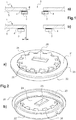
- the figure 1 shows a glass substrate pierced with a reinforced orifice according to the invention.
- a glass substrate 1 of the mineral glass sheet type comprises a through orifice 2.
- a ring-shaped reinforcing piece 3 is bonded by its bonding track 6 with glue 4 all around the hole 2 on a main face 5 of the glass substrate 1.
- the perimeter of the hole in the ring is smaller than that of the hole in the glass substrate and the reinforcement piece therefore hides part of the orifice.
- the hole in the glass substrate surrounds the hole in the reinforcement piece.
- the perimeter of the hole in the reinforcement piece is larger than the hole in the glass substrate (the hole surrounds the hole) and it is the hole in the reinforcement piece which is partially obscured by the main surface of the substrate.
- the hole in the reinforcement piece surrounds the hole in the glass substrate.
- the distance “d” between the edge of the orifice 2 of the substrate and the edge of the hole in the ring preferably does not exceed 5 mm.
- the figure 2 shows a reinforcing part which can be used to reinforce the orifice of a mineral glass substrate, said reinforcing part being seen in perspective and from two different sides.
- This reinforcing piece comprises a ring 20, the surface 21 of which comprises a gluing track surrounding the hole in the ring, said track being intended to be glued around the orifice of the glass substrate (not shown).
- This reinforcing piece is provided with a tubular part 22, the axis of which is also that of the ring.
- This tubular part 22 has two grooves 23 (only one can be seen, the other being identical but on the hidden side of the figure) which make it possible to clip a cover (not shown) which hides the entire reinforcement piece on the side seen on the figure. figure 2b ).
- a filling part 24 connects different points of the ring on the side of its glue track, said points being inside the perimeter of the glue track.
- This filling part 24 comprises a hole 25 for the passage of an electrical conductor (not shown).
- the filling part comprises a plurality of peripheral holes 26.
- the filling part projects from the bonding track and can be received in the housing formed in part by the orifice of the glass substrate.
- the LEDs contained in the reinforcement part in the housing that can be seen on the figure 2b ) under the filling part can send light rays through the peripheral holes 26 to directly impact the edge of the orifice in the glass substrate and continue their progression in the glass substrate parallel to it.
- the figure 3 shows a laminated glazing 30 of which a glass substrate 31 comprises an orifice 32, said orifice being provided with a reinforcing piece according to the invention also acting as a lighting device.
- This reinforcement piece is the one represented at figure 2 .
- the laminated glazing is here a motor vehicle roof.
- This laminated glazing comprises a first glass substrate 31 provided with an orifice 32 and a second glass substrate 33 without an orifice facing the orifice of the first glass substrate. These two glass substrates are glued together by means of a PVB 34 placed between them.
- the PVB was cut to form a recess 35 facing the orifice 32 of the first glass substrate.
- the PVB recess 35 is somewhat larger than the orifice 32 in the glass substrate.
- the reinforcing part comprises a ring 36 carrying a bonding track glued by adhesive 37 to the main surface 38 of the pierced glass substrate facing the interior of the passenger compartment of the motor vehicle.
- the reinforcement piece also comprises a tubular part 39 integral with the ring 36 and perpendicular to the ring, so that the axis of the ring (and therefore of its hole) and the axis of the tubular part coincide on the axis 52.
- a filling part 40 connected to the ring 36 is located in the housing formed both by the orifice 32 in the glass substrate and by the recess 35 in the PVB.
- This filling part is vis-à-vis the orifice of the glass substrate and vis-à-vis the hole formed by the ring of the reinforcing part. It is largely in the orifice of the glass substrate and is housed in the glazing.
- An electronic circuit 41 carrying LEDs 42 is contained in the reinforcement part in the housing formed by the hole 43 of the ring and the filling part 40.
- the filling part 40 protrudes from the bonding track of the ring. the ring 36.
- the LEDs 42 are exactly at the height of the wafer 44 of the first glass substrate so that their light passes through this wafer 44 and propagates in the wafer parallel to the glass substrate.
- the filling part 40 is in fact provided with peripheral holes 51 allowing the light from the LEDs to leave the housing receiving the electronic circuit inside the reinforcement piece, and to penetrate through the edge 44 of the glass substrate 31.
- a electrical conductor 45 embedded in the PVB 34 opens into the recess 35 of the PVB and the orifice 32 of the first glass substrate 31 and is connected by one of its ends 46 to the electronic circuit.
- a finishing piece 47 is clipped onto the reinforcement piece and hides the entire area of the orifice from view from inside the passenger compartment, including the reinforcement piece itself.
- the finishing piece notably carries a button 48 controlling an electrical switch carried by the electronic circuit to control the lighting.
- An LED 49 carried by the electronic device 41 is also provided to illuminate directly inside the passenger compartment of the vehicle through the finishing piece 47.
- the glass substrate 33 without orifice carries on its main face facing the first glass substrate 31 a black enamel 50 so as to hide the area of the glass. orifice 32 in view from the outside of the motor vehicle, that is to say through the roof of the vehicle and therefore through the substrate 33.
- the figure 4 represents the same piece of reinforcement as that of the figures 2 and 3 .
- the ring 60 of the reinforcing part and the bonding track 61 offering a bonding surface to surround the orifice of the glass substrate (not shown) directed towards the interior of the motor vehicle.
- a filling part 62 is connected to the reinforcement part and protrudes from the bonding track to be housed in the housing formed at least partially by the orifice of the glass substrate as well as in the recess of the PVB.
- This filling part comprises a hole 63 for the passage of an electrical conductor 64.
- the filling part 62 is provided with peripheral holes 65 so that the LEDs 66 can emit their light towards the edge of the orifice of the glass substrate.
- the figure 5 is a view of the lighting device containing the reinforcing part according to the invention seen from the interior passenger compartment of a motor vehicle.
- This device is fixed to the ceiling of the interior passenger compartment.
- This device includes the same parts as those shown in figures 2 , 3 and 4 .
- This lighting device is fixed by means of the reinforcing part according to the invention to the roof 70 of the vehicle which consists of a laminated glazing comprising a glass substrate, said device comprising a finishing part 71 clipped onto the part. reinforcement that it hides elsewhere.
- This finishing piece comprises three control buttons 72 acting directly on electrical switches fixed to the electronic circuit contained in the interior housing (not visible) formed by the reinforcement piece.
- a part of the finishing piece comprises a glass 73 letting through the light of an LED serving to illuminate the interior of the motor vehicle, said LED being able to be actuated by one of the buttons 72.
Landscapes
- Engineering & Computer Science (AREA)
- Mechanical Engineering (AREA)
- Joining Of Glass To Other Materials (AREA)
- Window Of Vehicle (AREA)
- Arrangements Of Lighting Devices For Vehicle Interiors, Mounting And Supporting Thereof, Circuits Therefore (AREA)
- Laminated Bodies (AREA)
Priority Applications (1)
| Application Number | Priority Date | Filing Date | Title |
|---|---|---|---|
| PL14718636T PL2961634T3 (pl) | 2013-02-26 | 2014-02-24 | Wzmocniony otwór w przeszkleniach |
Applications Claiming Priority (2)
| Application Number | Priority Date | Filing Date | Title |
|---|---|---|---|
| FR1351662A FR3002528B1 (fr) | 2013-02-26 | 2013-02-26 | Renfort d'orifice de vitrage |
| PCT/FR2014/050381 WO2014131972A1 (fr) | 2013-02-26 | 2014-02-24 | Renfort d'orifice de vitrage |
Publications (2)
| Publication Number | Publication Date |
|---|---|
| EP2961634A1 EP2961634A1 (fr) | 2016-01-06 |
| EP2961634B1 true EP2961634B1 (fr) | 2021-07-14 |
Family
ID=48692604
Family Applications (1)
| Application Number | Title | Priority Date | Filing Date |
|---|---|---|---|
| EP14718636.5A Active EP2961634B1 (fr) | 2013-02-26 | 2014-02-24 | Renfort d'orifice de vitrage |
Country Status (14)
| Country | Link |
|---|---|
| EP (1) | EP2961634B1 (pl) |
| JP (1) | JP6557149B2 (pl) |
| KR (1) | KR102183261B1 (pl) |
| CN (1) | CN104203651B (pl) |
| BR (1) | BR112015018792B1 (pl) |
| CA (1) | CA2902124A1 (pl) |
| EA (1) | EA031380B1 (pl) |
| ES (1) | ES2886762T3 (pl) |
| FR (1) | FR3002528B1 (pl) |
| HU (1) | HUE056349T2 (pl) |
| MX (1) | MX378616B (pl) |
| PL (1) | PL2961634T3 (pl) |
| PT (1) | PT2961634T (pl) |
| WO (1) | WO2014131972A1 (pl) |
Cited By (1)
| Publication number | Priority date | Publication date | Assignee | Title |
|---|---|---|---|---|
| EP4520561A4 (en) * | 2022-06-30 | 2025-09-24 | Fuyao Glass Ind Group Co Ltd | WINDOW AND VEHICLE GLASS ASSEMBLY |
Families Citing this family (8)
| Publication number | Priority date | Publication date | Assignee | Title |
|---|---|---|---|---|
| DE102016201882A1 (de) * | 2016-02-09 | 2017-08-10 | Bayerische Motoren Werke Aktiengesellschaft | Leuchtmodul eines Fahrzeugs |
| US10562274B1 (en) * | 2016-02-22 | 2020-02-18 | Apple Inc. | Glass fastening and sealing systems |
| FR3064531B1 (fr) | 2017-03-31 | 2019-04-05 | Saint-Gobain Glass France | Vitrage eclairant. |
| FR3084353B1 (fr) | 2018-07-27 | 2023-03-24 | Saint Gobain | Substrat emaille, dispositif vitre lumineux avec un tel substrat et sa fabrication. |
| FR3084355B1 (fr) | 2018-07-27 | 2023-05-19 | Saint Gobain | Substrat emaille, dispositif vitre lumineux automobile avec un tel substrat et sa fabrication. |
| FR3103808B1 (fr) | 2019-12-03 | 2022-05-27 | Saint Gobain | Outil de refroidissement local |
| FR3113008B1 (fr) * | 2020-07-31 | 2022-09-09 | Saint Gobain | VItrage LUMINEUx DE vehicule AuTOMOBILE et VEHICULE AuTOMOBILE AVEC UN TEL VITRAGE Lumineux |
| EP4043255B1 (en) * | 2021-02-11 | 2024-11-27 | Inalfa Roof Systems Group B.V. | Transparent roof panel having an isolated centre unit |
Citations (1)
| Publication number | Priority date | Publication date | Assignee | Title |
|---|---|---|---|---|
| WO2013110885A1 (fr) * | 2012-01-26 | 2013-08-01 | Saint-Gobain Glass France | Vitrage eclairant pour vehicule |
Family Cites Families (14)
| Publication number | Priority date | Publication date | Assignee | Title |
|---|---|---|---|---|
| FR1259744A (fr) | 1960-06-09 | 1961-04-28 | Palme pour propulsion ramée en milieu fluide | |
| JPH066580Y2 (ja) * | 1987-07-14 | 1994-02-16 | 日本板硝子株式会社 | 接続端子装置 |
| FR2630766B1 (fr) * | 1988-04-28 | 1992-07-24 | Saint Gobain Vitrage | Element de vitrage pour facade rideau |
| CA2353591C (en) * | 1999-10-04 | 2007-12-04 | Lothar Ginzel | Fixing device for panels |
| DE20218215U1 (de) * | 2002-11-22 | 2004-04-01 | Platz, Karl Otto | Befestigungsmittel für Verbundglasscheiben |
| EP1603744B1 (de) * | 2003-03-07 | 2011-11-30 | AGC Glass Europe | Transparentes element als verbundglaselement |
| DE10313664B3 (de) * | 2003-03-26 | 2004-10-21 | Daimlerchrysler Ag | Antennenbefestigungsvorrichtung |
| JP4638873B2 (ja) * | 2003-05-28 | 2011-02-23 | サン−ゴバン グラス フランス | 加熱層を備える積層要素 |
| DE202007016573U1 (de) * | 2007-04-11 | 2008-04-24 | Döppner Bauelemente GmbH & Co. KG | Verbundelement mit einem Befestigungselement |
| JP2008260881A (ja) * | 2007-04-13 | 2008-10-30 | Hori Glass Kk | 被着体、及び湿気硬化型接着剤を用いた接着方法 |
| FR2937711B1 (fr) * | 2008-10-27 | 2010-11-19 | Saint Gobain | Module a diodes electroluminescentes pour vehicule, support a diodes |
| KR20110098894A (ko) * | 2008-12-12 | 2011-09-02 | 아사히 가라스 가부시키가이샤 | 봉착 유리, 봉착 재료층 부착 유리 부재, 및 전자 디바이스와 그 제조 방법 |
| JP5472786B2 (ja) * | 2009-03-27 | 2014-04-16 | 日産自動車株式会社 | 自動車ガラスにおける位置決め用スペーサーの接着方法 |
| JP2010250966A (ja) * | 2009-04-10 | 2010-11-04 | Toshiba Lighting & Technology Corp | 照明器具 |
-
2013
- 2013-02-26 FR FR1351662A patent/FR3002528B1/fr not_active Expired - Fee Related
-
2014
- 2014-02-24 PL PL14718636T patent/PL2961634T3/pl unknown
- 2014-02-24 JP JP2015558533A patent/JP6557149B2/ja active Active
- 2014-02-24 WO PCT/FR2014/050381 patent/WO2014131972A1/fr not_active Ceased
- 2014-02-24 CN CN201480000599.7A patent/CN104203651B/zh active Active
- 2014-02-24 EA EA201591589A patent/EA031380B1/ru not_active IP Right Cessation
- 2014-02-24 BR BR112015018792-7A patent/BR112015018792B1/pt not_active IP Right Cessation
- 2014-02-24 HU HUE14718636A patent/HUE056349T2/hu unknown
- 2014-02-24 ES ES14718636T patent/ES2886762T3/es active Active
- 2014-02-24 MX MX2015011023A patent/MX378616B/es unknown
- 2014-02-24 EP EP14718636.5A patent/EP2961634B1/fr active Active
- 2014-02-24 KR KR1020157022641A patent/KR102183261B1/ko active Active
- 2014-02-24 CA CA2902124A patent/CA2902124A1/fr not_active Abandoned
- 2014-02-24 PT PT147186365T patent/PT2961634T/pt unknown
Patent Citations (1)
| Publication number | Priority date | Publication date | Assignee | Title |
|---|---|---|---|---|
| WO2013110885A1 (fr) * | 2012-01-26 | 2013-08-01 | Saint-Gobain Glass France | Vitrage eclairant pour vehicule |
Cited By (1)
| Publication number | Priority date | Publication date | Assignee | Title |
|---|---|---|---|---|
| EP4520561A4 (en) * | 2022-06-30 | 2025-09-24 | Fuyao Glass Ind Group Co Ltd | WINDOW AND VEHICLE GLASS ASSEMBLY |
Also Published As
| Publication number | Publication date |
|---|---|
| BR112015018792B1 (pt) | 2021-06-15 |
| KR102183261B1 (ko) | 2020-11-26 |
| PT2961634T (pt) | 2021-09-30 |
| WO2014131972A1 (fr) | 2014-09-04 |
| CN104203651B (zh) | 2019-04-30 |
| EP2961634A1 (fr) | 2016-01-06 |
| HUE056349T2 (hu) | 2022-02-28 |
| CN104203651A (zh) | 2014-12-10 |
| ES2886762T3 (es) | 2021-12-20 |
| EA201591589A1 (ru) | 2015-12-30 |
| BR112015018792A2 (pt) | 2017-07-18 |
| CA2902124A1 (fr) | 2014-09-04 |
| KR20150125933A (ko) | 2015-11-10 |
| JP2016515059A (ja) | 2016-05-26 |
| PL2961634T3 (pl) | 2021-12-20 |
| EA031380B1 (ru) | 2018-12-28 |
| FR3002528B1 (fr) | 2015-10-09 |
| MX2015011023A (es) | 2015-10-22 |
| JP6557149B2 (ja) | 2019-08-07 |
| MX378616B (es) | 2025-03-10 |
| FR3002528A1 (fr) | 2014-08-29 |
Similar Documents
| Publication | Publication Date | Title |
|---|---|---|
| EP2961634B1 (fr) | Renfort d'orifice de vitrage | |
| CA2624300C (fr) | Vitre feuilletee presentant un element de maintien integre | |
| EP2807046B1 (fr) | Vitrage eclairant pour vehicule | |
| EP2906421B1 (fr) | Vitrage feuillete | |
| EP2508042B1 (fr) | Vitrage a fils conducteurs integres par ultrasons | |
| EP3397484B1 (fr) | Procédé de fabrication d'un vitrage feuilleté de véhicule dans lequel est incorporé un écran oled | |
| EP2906422B1 (fr) | Fabrication d'un vitrage feuillete muni d'un conducteur electrique | |
| EP2737247B1 (fr) | Vitrage multiple lumineux de meuble | |
| CA2867840C (fr) | Vitrage eclairant pour vehicule | |
| CA2843411A1 (fr) | Vitrage lumineux de vehicule, fabrication | |
| KR20200079287A (ko) | 전기적 부착 부품이 통합된 적층 판유리 | |
| FR3070547A1 (fr) | Radome a decoration retro-illuminee | |
| FR2936588A1 (fr) | Element d'habillage lumineux assurant un eclairage d'ambiance multidirectionnel, notamment pour vehicule automobile, et piece d'equipement interieur equipee d'un tel element | |
| EP4061629B1 (fr) | Vitrage feuilleté pour véhicule aérien léger, chauffant sur une partie de sa surface | |
| FR2991937A1 (fr) | Element de garnissage comprenant une couche de decor translucide retroeclairee | |
| WO2025109036A1 (fr) | Vitrage de vehicule a support aimante | |
| FR2957556A1 (fr) | Fenestron multifonctionnel et vehicule equipe dudit fenestron. | |
| FR3125744A1 (fr) | Toile d’occultation stratifiée, occulteur présentant une telle toile et procédé de fabrication d’une telle toile d’occultation stratifiée. | |
| FR3105084A1 (fr) | Vitrage feuilleté à couche chauffante au même niveau de la structure feuilletée que le masque des amenées de courant électrique de la couche chauffante |
Legal Events
| Date | Code | Title | Description |
|---|---|---|---|
| PUAI | Public reference made under article 153(3) epc to a published international application that has entered the european phase |
Free format text: ORIGINAL CODE: 0009012 |
|
| 17P | Request for examination filed |
Effective date: 20150928 |
|
| AK | Designated contracting states |
Kind code of ref document: A1 Designated state(s): AL AT BE BG CH CY CZ DE DK EE ES FI FR GB GR HR HU IE IS IT LI LT LU LV MC MK MT NL NO PL PT RO RS SE SI SK SM TR |
|
| AX | Request for extension of the european patent |
Extension state: BA ME |
|
| DAX | Request for extension of the european patent (deleted) | ||
| STAA | Information on the status of an ep patent application or granted ep patent |
Free format text: STATUS: EXAMINATION IS IN PROGRESS |
|
| 17Q | First examination report despatched |
Effective date: 20190909 |
|
| RAP1 | Party data changed (applicant data changed or rights of an application transferred) |
Owner name: SAINT-GOBAIN GLASS FRANCE |
|
| REG | Reference to a national code |
Ref country code: DE Ref legal event code: R079 Ref document number: 602014078739 Country of ref document: DE Free format text: PREVIOUS MAIN CLASS: B60Q0003020000 Ipc: B62D0025060000 |
|
| GRAP | Despatch of communication of intention to grant a patent |
Free format text: ORIGINAL CODE: EPIDOSNIGR1 |
|
| STAA | Information on the status of an ep patent application or granted ep patent |
Free format text: STATUS: GRANT OF PATENT IS INTENDED |
|
| RIC1 | Information provided on ipc code assigned before grant |
Ipc: F21V 8/00 20060101ALI20200730BHEP Ipc: B62D 25/06 20060101AFI20200730BHEP Ipc: B60Q 3/208 20170101ALI20200730BHEP Ipc: B32B 17/10 20060101ALI20200730BHEP Ipc: F21V 23/00 20150101ALI20200730BHEP |
|
| INTG | Intention to grant announced |
Effective date: 20200827 |
|
| GRAJ | Information related to disapproval of communication of intention to grant by the applicant or resumption of examination proceedings by the epo deleted |
Free format text: ORIGINAL CODE: EPIDOSDIGR1 |
|
| STAA | Information on the status of an ep patent application or granted ep patent |
Free format text: STATUS: EXAMINATION IS IN PROGRESS |
|
| INTC | Intention to grant announced (deleted) | ||
| GRAP | Despatch of communication of intention to grant a patent |
Free format text: ORIGINAL CODE: EPIDOSNIGR1 |
|
| STAA | Information on the status of an ep patent application or granted ep patent |
Free format text: STATUS: GRANT OF PATENT IS INTENDED |
|
| INTG | Intention to grant announced |
Effective date: 20210215 |
|
| GRAS | Grant fee paid |
Free format text: ORIGINAL CODE: EPIDOSNIGR3 |
|
| GRAA | (expected) grant |
Free format text: ORIGINAL CODE: 0009210 |
|
| STAA | Information on the status of an ep patent application or granted ep patent |
Free format text: STATUS: THE PATENT HAS BEEN GRANTED |
|
| AK | Designated contracting states |
Kind code of ref document: B1 Designated state(s): AL AT BE BG CH CY CZ DE DK EE ES FI FR GB GR HR HU IE IS IT LI LT LU LV MC MK MT NL NO PL PT RO RS SE SI SK SM TR |
|
| REG | Reference to a national code |
Ref country code: GB Ref legal event code: FG4D Free format text: NOT ENGLISH |
|
| REG | Reference to a national code |
Ref country code: IE Ref legal event code: FG4D Free format text: LANGUAGE OF EP DOCUMENT: FRENCH |
|
| REG | Reference to a national code |
Ref country code: DE Ref legal event code: R096 Ref document number: 602014078739 Country of ref document: DE |
|
| REG | Reference to a national code |
Ref country code: AT Ref legal event code: REF Ref document number: 1410424 Country of ref document: AT Kind code of ref document: T Effective date: 20210815 |
|
| REG | Reference to a national code |
Ref country code: NL Ref legal event code: FP |
|
| REG | Reference to a national code |
Ref country code: RO Ref legal event code: EPE |
|
| REG | Reference to a national code |
Ref country code: PT Ref legal event code: SC4A Ref document number: 2961634 Country of ref document: PT Date of ref document: 20210930 Kind code of ref document: T Free format text: AVAILABILITY OF NATIONAL TRANSLATION Effective date: 20210924 |
|
| REG | Reference to a national code |
Ref country code: SE Ref legal event code: TRGR |
|
| REG | Reference to a national code |
Ref country code: SK Ref legal event code: T3 Ref document number: E 38160 Country of ref document: SK Ref country code: LT Ref legal event code: MG9D |
|
| REG | Reference to a national code |
Ref country code: AT Ref legal event code: MK05 Ref document number: 1410424 Country of ref document: AT Kind code of ref document: T Effective date: 20210714 |
|
| REG | Reference to a national code |
Ref country code: ES Ref legal event code: FG2A Ref document number: 2886762 Country of ref document: ES Kind code of ref document: T3 Effective date: 20211220 |
|
| PG25 | Lapsed in a contracting state [announced via postgrant information from national office to epo] |
Ref country code: LT Free format text: LAPSE BECAUSE OF FAILURE TO SUBMIT A TRANSLATION OF THE DESCRIPTION OR TO PAY THE FEE WITHIN THE PRESCRIBED TIME-LIMIT Effective date: 20210714 Ref country code: BG Free format text: LAPSE BECAUSE OF FAILURE TO SUBMIT A TRANSLATION OF THE DESCRIPTION OR TO PAY THE FEE WITHIN THE PRESCRIBED TIME-LIMIT Effective date: 20211014 Ref country code: AT Free format text: LAPSE BECAUSE OF FAILURE TO SUBMIT A TRANSLATION OF THE DESCRIPTION OR TO PAY THE FEE WITHIN THE PRESCRIBED TIME-LIMIT Effective date: 20210714 Ref country code: FI Free format text: LAPSE BECAUSE OF FAILURE TO SUBMIT A TRANSLATION OF THE DESCRIPTION OR TO PAY THE FEE WITHIN THE PRESCRIBED TIME-LIMIT Effective date: 20210714 Ref country code: NO Free format text: LAPSE BECAUSE OF FAILURE TO SUBMIT A TRANSLATION OF THE DESCRIPTION OR TO PAY THE FEE WITHIN THE PRESCRIBED TIME-LIMIT Effective date: 20211014 Ref country code: RS Free format text: LAPSE BECAUSE OF FAILURE TO SUBMIT A TRANSLATION OF THE DESCRIPTION OR TO PAY THE FEE WITHIN THE PRESCRIBED TIME-LIMIT Effective date: 20210714 Ref country code: HR Free format text: LAPSE BECAUSE OF FAILURE TO SUBMIT A TRANSLATION OF THE DESCRIPTION OR TO PAY THE FEE WITHIN THE PRESCRIBED TIME-LIMIT Effective date: 20210714 |
|
| PGFP | Annual fee paid to national office [announced via postgrant information from national office to epo] |
Ref country code: SE Payment date: 20211229 Year of fee payment: 9 |
|
| PG25 | Lapsed in a contracting state [announced via postgrant information from national office to epo] |
Ref country code: LV Free format text: LAPSE BECAUSE OF FAILURE TO SUBMIT A TRANSLATION OF THE DESCRIPTION OR TO PAY THE FEE WITHIN THE PRESCRIBED TIME-LIMIT Effective date: 20210714 Ref country code: GR Free format text: LAPSE BECAUSE OF FAILURE TO SUBMIT A TRANSLATION OF THE DESCRIPTION OR TO PAY THE FEE WITHIN THE PRESCRIBED TIME-LIMIT Effective date: 20211015 |
|
| REG | Reference to a national code |
Ref country code: HU Ref legal event code: AG4A Ref document number: E056349 Country of ref document: HU |
|
| REG | Reference to a national code |
Ref country code: DE Ref legal event code: R097 Ref document number: 602014078739 Country of ref document: DE |
|
| PG25 | Lapsed in a contracting state [announced via postgrant information from national office to epo] |
Ref country code: DK Free format text: LAPSE BECAUSE OF FAILURE TO SUBMIT A TRANSLATION OF THE DESCRIPTION OR TO PAY THE FEE WITHIN THE PRESCRIBED TIME-LIMIT Effective date: 20210714 |
|
| PGFP | Annual fee paid to national office [announced via postgrant information from national office to epo] |
Ref country code: HU Payment date: 20220112 Year of fee payment: 9 |
|
| PLBE | No opposition filed within time limit |
Free format text: ORIGINAL CODE: 0009261 |
|
| STAA | Information on the status of an ep patent application or granted ep patent |
Free format text: STATUS: NO OPPOSITION FILED WITHIN TIME LIMIT |
|
| PG25 | Lapsed in a contracting state [announced via postgrant information from national office to epo] |
Ref country code: SM Free format text: LAPSE BECAUSE OF FAILURE TO SUBMIT A TRANSLATION OF THE DESCRIPTION OR TO PAY THE FEE WITHIN THE PRESCRIBED TIME-LIMIT Effective date: 20210714 Ref country code: EE Free format text: LAPSE BECAUSE OF FAILURE TO SUBMIT A TRANSLATION OF THE DESCRIPTION OR TO PAY THE FEE WITHIN THE PRESCRIBED TIME-LIMIT Effective date: 20210714 Ref country code: AL Free format text: LAPSE BECAUSE OF FAILURE TO SUBMIT A TRANSLATION OF THE DESCRIPTION OR TO PAY THE FEE WITHIN THE PRESCRIBED TIME-LIMIT Effective date: 20210714 |
|
| PGFP | Annual fee paid to national office [announced via postgrant information from national office to epo] |
Ref country code: TR Payment date: 20220222 Year of fee payment: 9 Ref country code: SK Payment date: 20220113 Year of fee payment: 9 Ref country code: RO Payment date: 20220127 Year of fee payment: 9 Ref country code: PT Payment date: 20220223 Year of fee payment: 9 Ref country code: PL Payment date: 20211231 Year of fee payment: 9 Ref country code: NL Payment date: 20220118 Year of fee payment: 9 Ref country code: LU Payment date: 20220214 Year of fee payment: 9 Ref country code: IT Payment date: 20220111 Year of fee payment: 9 Ref country code: ES Payment date: 20220307 Year of fee payment: 9 Ref country code: CZ Payment date: 20220126 Year of fee payment: 9 Ref country code: BE Payment date: 20220118 Year of fee payment: 9 |
|
| 26N | No opposition filed |
Effective date: 20220419 |
|
| PG25 | Lapsed in a contracting state [announced via postgrant information from national office to epo] |
Ref country code: MC Free format text: LAPSE BECAUSE OF FAILURE TO SUBMIT A TRANSLATION OF THE DESCRIPTION OR TO PAY THE FEE WITHIN THE PRESCRIBED TIME-LIMIT Effective date: 20210714 |
|
| REG | Reference to a national code |
Ref country code: CH Ref legal event code: PL |
|
| PG25 | Lapsed in a contracting state [announced via postgrant information from national office to epo] |
Ref country code: LI Free format text: LAPSE BECAUSE OF NON-PAYMENT OF DUE FEES Effective date: 20220228 Ref country code: IE Free format text: LAPSE BECAUSE OF NON-PAYMENT OF DUE FEES Effective date: 20220224 Ref country code: CH Free format text: LAPSE BECAUSE OF NON-PAYMENT OF DUE FEES Effective date: 20220228 |
|
| REG | Reference to a national code |
Ref country code: SE Ref legal event code: EUG |
|
| REG | Reference to a national code |
Ref country code: NL Ref legal event code: MM Effective date: 20230301 |
|
| REG | Reference to a national code |
Ref country code: SK Ref legal event code: MM4A Ref document number: E 38160 Country of ref document: SK Effective date: 20230224 |
|
| REG | Reference to a national code |
Ref country code: BE Ref legal event code: MM Effective date: 20230228 |
|
| PG25 | Lapsed in a contracting state [announced via postgrant information from national office to epo] |
Ref country code: SE Free format text: LAPSE BECAUSE OF NON-PAYMENT OF DUE FEES Effective date: 20230225 Ref country code: RO Free format text: LAPSE BECAUSE OF NON-PAYMENT OF DUE FEES Effective date: 20230224 Ref country code: PT Free format text: LAPSE BECAUSE OF NON-PAYMENT OF DUE FEES Effective date: 20230824 Ref country code: LU Free format text: LAPSE BECAUSE OF NON-PAYMENT OF DUE FEES Effective date: 20230224 Ref country code: CZ Free format text: LAPSE BECAUSE OF NON-PAYMENT OF DUE FEES Effective date: 20230224 |
|
| PG25 | Lapsed in a contracting state [announced via postgrant information from national office to epo] |
Ref country code: SK Free format text: LAPSE BECAUSE OF NON-PAYMENT OF DUE FEES Effective date: 20230224 Ref country code: NL Free format text: LAPSE BECAUSE OF NON-PAYMENT OF DUE FEES Effective date: 20230301 Ref country code: HU Free format text: LAPSE BECAUSE OF NON-PAYMENT OF DUE FEES Effective date: 20230225 |
|
| PG25 | Lapsed in a contracting state [announced via postgrant information from national office to epo] |
Ref country code: IT Free format text: LAPSE BECAUSE OF NON-PAYMENT OF DUE FEES Effective date: 20230224 |
|
| PG25 | Lapsed in a contracting state [announced via postgrant information from national office to epo] |
Ref country code: BE Free format text: LAPSE BECAUSE OF NON-PAYMENT OF DUE FEES Effective date: 20230228 |
|
| PG25 | Lapsed in a contracting state [announced via postgrant information from national office to epo] |
Ref country code: ES Free format text: LAPSE BECAUSE OF NON-PAYMENT OF DUE FEES Effective date: 20230225 |
|
| REG | Reference to a national code |
Ref country code: ES Ref legal event code: FD2A Effective date: 20240426 |
|
| PG25 | Lapsed in a contracting state [announced via postgrant information from national office to epo] |
Ref country code: MK Free format text: LAPSE BECAUSE OF FAILURE TO SUBMIT A TRANSLATION OF THE DESCRIPTION OR TO PAY THE FEE WITHIN THE PRESCRIBED TIME-LIMIT Effective date: 20210714 Ref country code: ES Free format text: LAPSE BECAUSE OF NON-PAYMENT OF DUE FEES Effective date: 20230225 Ref country code: CY Free format text: LAPSE BECAUSE OF FAILURE TO SUBMIT A TRANSLATION OF THE DESCRIPTION OR TO PAY THE FEE WITHIN THE PRESCRIBED TIME-LIMIT Effective date: 20210714 |
|
| PG25 | Lapsed in a contracting state [announced via postgrant information from national office to epo] |
Ref country code: MT Free format text: LAPSE BECAUSE OF FAILURE TO SUBMIT A TRANSLATION OF THE DESCRIPTION OR TO PAY THE FEE WITHIN THE PRESCRIBED TIME-LIMIT Effective date: 20210714 |
|
| PG25 | Lapsed in a contracting state [announced via postgrant information from national office to epo] |
Ref country code: PL Free format text: LAPSE BECAUSE OF NON-PAYMENT OF DUE FEES Effective date: 20230224 |
|
| PG25 | Lapsed in a contracting state [announced via postgrant information from national office to epo] |
Ref country code: PL Free format text: LAPSE BECAUSE OF NON-PAYMENT OF DUE FEES Effective date: 20230224 |
|
| REG | Reference to a national code |
Ref country code: DE Ref legal event code: R081 Ref document number: 602014078739 Country of ref document: DE Owner name: SAINT-GOBAIN SEKURIT FRANCE, FR Free format text: FORMER OWNER: SAINT-GOBAIN GLASS FRANCE, COURBEVOIE, FR |
|
| REG | Reference to a national code |
Ref country code: GB Ref legal event code: 732E Free format text: REGISTERED BETWEEN 20250703 AND 20250709 |
|
| PGFP | Annual fee paid to national office [announced via postgrant information from national office to epo] |
Ref country code: FR Payment date: 20251231 Year of fee payment: 13 |
|
| PGFP | Annual fee paid to national office [announced via postgrant information from national office to epo] |
Ref country code: GB Payment date: 20260106 Year of fee payment: 13 |
|
| PGFP | Annual fee paid to national office [announced via postgrant information from national office to epo] |
Ref country code: DE Payment date: 20260102 Year of fee payment: 13 |