EP2961192A1 - Program and method for controlling information terminal - Google Patents
Program and method for controlling information terminal Download PDFInfo
- Publication number
- EP2961192A1 EP2961192A1 EP14754062.9A EP14754062A EP2961192A1 EP 2961192 A1 EP2961192 A1 EP 2961192A1 EP 14754062 A EP14754062 A EP 14754062A EP 2961192 A1 EP2961192 A1 EP 2961192A1
- Authority
- EP
- European Patent Office
- Prior art keywords
- curtain
- electric
- display
- screen
- curtain device
- Prior art date
- Legal status (The legal status is an assumption and is not a legal conclusion. Google has not performed a legal analysis and makes no representation as to the accuracy of the status listed.)
- Granted
Links
Images


Classifications
-
- G—PHYSICS
- G06—COMPUTING; CALCULATING OR COUNTING
- G06F—ELECTRIC DIGITAL DATA PROCESSING
- G06F3/00—Input arrangements for transferring data to be processed into a form capable of being handled by the computer; Output arrangements for transferring data from processing unit to output unit, e.g. interface arrangements
- G06F3/01—Input arrangements or combined input and output arrangements for interaction between user and computer
- G06F3/048—Interaction techniques based on graphical user interfaces [GUI]
- G06F3/0484—Interaction techniques based on graphical user interfaces [GUI] for the control of specific functions or operations, e.g. selecting or manipulating an object, an image or a displayed text element, setting a parameter value or selecting a range
- G06F3/04847—Interaction techniques to control parameter settings, e.g. interaction with sliders or dials
-
- A—HUMAN NECESSITIES
- A47—FURNITURE; DOMESTIC ARTICLES OR APPLIANCES; COFFEE MILLS; SPICE MILLS; SUCTION CLEANERS IN GENERAL
- A47H—FURNISHINGS FOR WINDOWS OR DOORS
- A47H5/00—Devices for drawing draperies, curtains, or the like
- A47H5/02—Devices for opening and closing curtains
-
- E—FIXED CONSTRUCTIONS
- E06—DOORS, WINDOWS, SHUTTERS, OR ROLLER BLINDS IN GENERAL; LADDERS
- E06B—FIXED OR MOVABLE CLOSURES FOR OPENINGS IN BUILDINGS, VEHICLES, FENCES OR LIKE ENCLOSURES IN GENERAL, e.g. DOORS, WINDOWS, BLINDS, GATES
- E06B3/00—Window sashes, door leaves, or like elements for closing wall or like openings; Layout of fixed or moving closures, e.g. windows in wall or like openings; Features of rigidly-mounted outer frames relating to the mounting of wing frames
- E06B3/32—Arrangements of wings characterised by the manner of movement; Arrangements of movable wings in openings; Features of wings or frames relating solely to the manner of movement of the wing
- E06B3/48—Wings connected at their edges, e.g. foldable wings
- E06B3/485—Sectional doors
-
- E—FIXED CONSTRUCTIONS
- E06—DOORS, WINDOWS, SHUTTERS, OR ROLLER BLINDS IN GENERAL; LADDERS
- E06B—FIXED OR MOVABLE CLOSURES FOR OPENINGS IN BUILDINGS, VEHICLES, FENCES OR LIKE ENCLOSURES IN GENERAL, e.g. DOORS, WINDOWS, BLINDS, GATES
- E06B9/00—Screening or protective devices for wall or similar openings, with or without operating or securing mechanisms; Closures of similar construction
- E06B9/24—Screens or other constructions affording protection against light, especially against sunshine; Similar screens for privacy or appearance; Slat blinds
- E06B9/26—Lamellar or like blinds, e.g. venetian blinds
- E06B9/28—Lamellar or like blinds, e.g. venetian blinds with horizontal lamellae, e.g. non-liftable
- E06B9/30—Lamellar or like blinds, e.g. venetian blinds with horizontal lamellae, e.g. non-liftable liftable
- E06B9/32—Operating, guiding, or securing devices therefor
-
- G—PHYSICS
- G06—COMPUTING; CALCULATING OR COUNTING
- G06F—ELECTRIC DIGITAL DATA PROCESSING
- G06F3/00—Input arrangements for transferring data to be processed into a form capable of being handled by the computer; Output arrangements for transferring data from processing unit to output unit, e.g. interface arrangements
- G06F3/01—Input arrangements or combined input and output arrangements for interaction between user and computer
- G06F3/048—Interaction techniques based on graphical user interfaces [GUI]
- G06F3/0481—Interaction techniques based on graphical user interfaces [GUI] based on specific properties of the displayed interaction object or a metaphor-based environment, e.g. interaction with desktop elements like windows or icons, or assisted by a cursor's changing behaviour or appearance
- G06F3/04817—Interaction techniques based on graphical user interfaces [GUI] based on specific properties of the displayed interaction object or a metaphor-based environment, e.g. interaction with desktop elements like windows or icons, or assisted by a cursor's changing behaviour or appearance using icons
-
- G—PHYSICS
- G06—COMPUTING; CALCULATING OR COUNTING
- G06F—ELECTRIC DIGITAL DATA PROCESSING
- G06F3/00—Input arrangements for transferring data to be processed into a form capable of being handled by the computer; Output arrangements for transferring data from processing unit to output unit, e.g. interface arrangements
- G06F3/01—Input arrangements or combined input and output arrangements for interaction between user and computer
- G06F3/048—Interaction techniques based on graphical user interfaces [GUI]
- G06F3/0481—Interaction techniques based on graphical user interfaces [GUI] based on specific properties of the displayed interaction object or a metaphor-based environment, e.g. interaction with desktop elements like windows or icons, or assisted by a cursor's changing behaviour or appearance
- G06F3/0482—Interaction with lists of selectable items, e.g. menus
-
- G—PHYSICS
- G06—COMPUTING; CALCULATING OR COUNTING
- G06F—ELECTRIC DIGITAL DATA PROCESSING
- G06F3/00—Input arrangements for transferring data to be processed into a form capable of being handled by the computer; Output arrangements for transferring data from processing unit to output unit, e.g. interface arrangements
- G06F3/01—Input arrangements or combined input and output arrangements for interaction between user and computer
- G06F3/048—Interaction techniques based on graphical user interfaces [GUI]
- G06F3/0484—Interaction techniques based on graphical user interfaces [GUI] for the control of specific functions or operations, e.g. selecting or manipulating an object, an image or a displayed text element, setting a parameter value or selecting a range
- G06F3/04842—Selection of displayed objects or displayed text elements
-
- G—PHYSICS
- G06—COMPUTING; CALCULATING OR COUNTING
- G06F—ELECTRIC DIGITAL DATA PROCESSING
- G06F3/00—Input arrangements for transferring data to be processed into a form capable of being handled by the computer; Output arrangements for transferring data from processing unit to output unit, e.g. interface arrangements
- G06F3/01—Input arrangements or combined input and output arrangements for interaction between user and computer
- G06F3/048—Interaction techniques based on graphical user interfaces [GUI]
- G06F3/0487—Interaction techniques based on graphical user interfaces [GUI] using specific features provided by the input device, e.g. functions controlled by the rotation of a mouse with dual sensing arrangements, or of the nature of the input device, e.g. tap gestures based on pressure sensed by a digitiser
- G06F3/0488—Interaction techniques based on graphical user interfaces [GUI] using specific features provided by the input device, e.g. functions controlled by the rotation of a mouse with dual sensing arrangements, or of the nature of the input device, e.g. tap gestures based on pressure sensed by a digitiser using a touch-screen or digitiser, e.g. input of commands through traced gestures
- G06F3/04883—Interaction techniques based on graphical user interfaces [GUI] using specific features provided by the input device, e.g. functions controlled by the rotation of a mouse with dual sensing arrangements, or of the nature of the input device, e.g. tap gestures based on pressure sensed by a digitiser using a touch-screen or digitiser, e.g. input of commands through traced gestures for inputting data by handwriting, e.g. gesture or text
-
- G—PHYSICS
- G08—SIGNALLING
- G08C—TRANSMISSION SYSTEMS FOR MEASURED VALUES, CONTROL OR SIMILAR SIGNALS
- G08C17/00—Arrangements for transmitting signals characterised by the use of a wireless electrical link
-
- H—ELECTRICITY
- H04—ELECTRIC COMMUNICATION TECHNIQUE
- H04L—TRANSMISSION OF DIGITAL INFORMATION, e.g. TELEGRAPHIC COMMUNICATION
- H04L12/00—Data switching networks
- H04L12/28—Data switching networks characterised by path configuration, e.g. LAN [Local Area Networks] or WAN [Wide Area Networks]
- H04L12/2803—Home automation networks
- H04L12/2816—Controlling appliance services of a home automation network by calling their functionalities
- H04L12/282—Controlling appliance services of a home automation network by calling their functionalities based on user interaction within the home
-
- H—ELECTRICITY
- H04—ELECTRIC COMMUNICATION TECHNIQUE
- H04L—TRANSMISSION OF DIGITAL INFORMATION, e.g. TELEGRAPHIC COMMUNICATION
- H04L67/00—Network arrangements or protocols for supporting network services or applications
- H04L67/01—Protocols
- H04L67/02—Protocols based on web technology, e.g. hypertext transfer protocol [HTTP]
- H04L67/025—Protocols based on web technology, e.g. hypertext transfer protocol [HTTP] for remote control or remote monitoring of applications
-
- A—HUMAN NECESSITIES
- A47—FURNITURE; DOMESTIC ARTICLES OR APPLIANCES; COFFEE MILLS; SPICE MILLS; SUCTION CLEANERS IN GENERAL
- A47H—FURNISHINGS FOR WINDOWS OR DOORS
- A47H5/00—Devices for drawing draperies, curtains, or the like
- A47H5/02—Devices for opening and closing curtains
- A47H2005/025—Devices for opening and closing curtains controlled by electronic sensors
-
- G—PHYSICS
- G06—COMPUTING; CALCULATING OR COUNTING
- G06F—ELECTRIC DIGITAL DATA PROCESSING
- G06F2203/00—Indexing scheme relating to G06F3/00 - G06F3/048
- G06F2203/048—Indexing scheme relating to G06F3/048
- G06F2203/04808—Several contacts: gestures triggering a specific function, e.g. scrolling, zooming, right-click, when the user establishes several contacts with the surface simultaneously; e.g. using several fingers or a combination of fingers and pen
-
- G—PHYSICS
- G08—SIGNALLING
- G08C—TRANSMISSION SYSTEMS FOR MEASURED VALUES, CONTROL OR SIMILAR SIGNALS
- G08C2201/00—Transmission systems of control signals via wireless link
- G08C2201/30—User interface
-
- G—PHYSICS
- G08—SIGNALLING
- G08C—TRANSMISSION SYSTEMS FOR MEASURED VALUES, CONTROL OR SIMILAR SIGNALS
- G08C2201/00—Transmission systems of control signals via wireless link
- G08C2201/40—Remote control systems using repeaters, converters, gateways
-
- G—PHYSICS
- G08—SIGNALLING
- G08C—TRANSMISSION SYSTEMS FOR MEASURED VALUES, CONTROL OR SIMILAR SIGNALS
- G08C2201/00—Transmission systems of control signals via wireless link
- G08C2201/50—Receiving or transmitting feedback, e.g. replies, status updates, acknowledgements, from the controlled devices
Abstract
Description
- The present disclosure relates to a method for controlling an information apparatus and a program.
- A variety of proposals have been made for open/close control for a curtain of an electric curtain device.
-
Patent Document 1 relates to a motor-operated wireless remote control system for an electric curtain. The system includes a motor-side device 2 having amotor 4, amotor control device 5, and aconverter 6, and awireless remote controller 3 having atransmitter 21 and areceiver 22. Theconverter 6 converts AC from a commercial power source into DC to supply DC electric power to themotor 4 and themotor control device 5, and is connected to a powersource output terminal 8 provided to the motor-side device 2. A power source input terminal 51 of thereceiver 22 can be connected to the powersource output terminal 8. -
Patent Document 2 discloses a technology in which a sound generated by a telephone set is input, a command from the outside is recognized in accordance with the sound generated by the telephone set, and a drive motor that opens and closes a curtain is actuated in accordance with a control signal corresponding to the command. -
Patent Document 3 relates to an electric curtain open/close device. The electric curtain device is provided with a carriage provided directly above a plurality of curtain rails to be moved in parallel with the curtain rails by a motor. A solenoid is mounted on the carriage corresponding to each of the curtain rails. Curtains are hung from the curtain rails by curtain rings including a ferromagnetic portion. When the carriage is moved with a current applied to the solenoid, a curtain ring corresponding to the solenoid is attracted by a magnetic force and the curtain is pulled. When the curtain is pulled to a desired position, the current applied to the solenoid is stopped, which disconnects the curtain ring from the solenoid to stop the curtain at the desired position. - However,
Patent Documents 1 to 3 described above need a further improvement. -
- Patent Document 1:
Japanese Patent Application Laid-open No. 2012-50653 Fig. 1 ) - Patent Document 2:
Japanese Patent Application Laid-open No. 2003-348250 - Patent Document 3:
Japanese Patent Application Laid-open No. 2004-166980 - In order to address the foregoing issue, an aspect of the present invention is a method for controlling an information apparatus, the information apparatus having a touch panel display and being connected to a network, an electric curtain device being controlled over the network, the electric curtain device being capable of opening and closing a curtain through remote operation,
the method causing a computer of the information apparatus to: - display an operation icon on a display screen of the information apparatus, the operation icon causing an operation screen for the electric curtain device to be displayed;
- display the operation screen for the electric curtain device when selection of the operation icon is sensed, the operation screen including a curtain image representing the curtain of the electric curtain device; and
- when a pinch-out operation is sensed on the operation screen, output to the network a first open control command for opening the curtain of the electric curtain device.
- According to the aspect described above, it is possible to embody a further improvement.
-
-
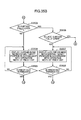
Fig. 1 is a diagram showing an overall configuration of a curtain control system according to an embodiment of the present disclosure. -
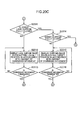
Fig. 2 is a block diagram showing an electrical configuration of an operation terminal and an electric curtain system according to the embodiment of the present disclosure. -
Fig. 3 is a diagram schematically showing a configuration of an electric curtain system according to an embodiment of the present disclosure. -
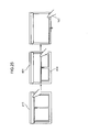
Fig. 4 is a diagram showing a configuration example of the form of implementation of the operation terminal according to an embodiment of the present disclosure. -
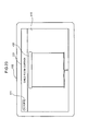
Fig. 5 is a diagram showing a display example of a menu screen displayed on a display for a case where a tablet is used as the operation terminal. -
Fig. 6 is a diagram showing a display example of the menu screen displayed on the display for a case where a smartphone is used as the operation terminal. -
Fig. 7 is a diagram showing an example of a curtain select screen displayed on the display of the operation terminal. -
Fig. 8 is a diagram showing an example of a curtain control screen displayed on the display of the operation terminal. -
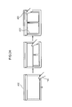
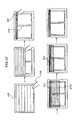
Fig. 9 is a diagram showing a display example of the curtain control screen and an operation example by the contacting object during an open-close operation for the curtain. -
Fig. 10 is a diagram showing a display example of the curtain control screen and an operation example by the contacting object during an open-close operation for the curtain. -
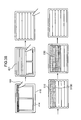
Fig. 11 is a diagram showing a display example of the curtain control screen and an operation example by the contacting object during an open-close operation for the lace curtain. -
Fig. 12 is a diagram showing a display example of the curtain control screen and an operation example by the contacting object during an open-close operation for the lace curtain. -
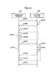
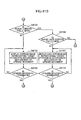
Fig. 13 is a sequence diagram showing a process flow in the operation terminal and the electric curtain system. -
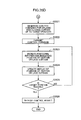
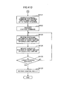
Fig. 14 is a flowchart showing a process flow for the operation terminal to control the electric curtain system. -
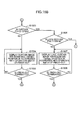
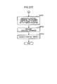
Fig. 15A is a flowchart showing a process flow for the operation terminal to generate and transmit a control command for controlling the curtain and the lace curtain of the electric curtain system. -
Fig. 15B is a flowchart showing a process flow for the operation terminal to generate and transmit a control command for controlling the curtain and the lace curtain of the electric curtain system. -
Fig. 15C is a flowchart showing a process flow for the operation terminal to generate and transmit a control command for controlling the curtain and the lace curtain of the electric curtain system. -
Fig. 15D is a flowchart showing a process flow for the operation terminal to generate and transmit a control command for controlling the curtain and the lace curtain of the electric curtain system. -
Fig. 16 is a flowchart showing a process flow in the electric curtain system. -
Fig. 17 is a diagram showing an example, different fromFig. 8 , of the curtain control screen displayed on the display of the operation terminal. -
Fig. 18 is a diagram showing an operation example by the contacting object and a display example of the curtain control screen during open-close control for a shade curtain. -
Fig. 19 is a diagram showing an operation example by the contacting object and a display example of the curtain control screen during open-close control for a shade curtain. -
Fig. 20A is a flowchart showing a process flow for the operation terminal to generate and transmit a control command for controlling the shade curtain and a shade lace curtain of the electric curtain system. -
Fig. 20B is a flowchart showing a process flow for the operation terminal to generate and transmit a control command for controlling the shade curtain and the shade lace curtain of the electric curtain system. -
Fig. 20C is a flowchart showing a process flow for the operation terminal to generate and transmit a control command for controlling the shade curtain and the shade lace curtain of the electric curtain system. -
Fig. 20D is a flowchart showing a process flow for the operation terminal to generate and transmit a control command for controlling the shade curtain and the shade lace curtain of the electric curtain system. -
Fig. 21 is a diagram showing a display example of the curtain control screen and an operation example by the contacting object during open-close control for a one-way draw curtain. -
Fig. 22 is a diagram showing a display example of the curtain control screen and an operation example by the contacting object during open-close control for a one-way draw curtain. -
Fig. 23 is a diagram showing a further different example of the curtain control screen displayed on the display of the operation terminal. -
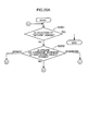
Fig. 24 is a diagram showing a display example of the curtain control screen and an operation example by the contacting object during open-close control for a roll screen. -
Fig. 25 is a diagram showing a display example of the curtain control screen and an operation example by the contacting object during open-close control for a roll screen. -
Fig. 26 is a diagram showing a further different example of the curtain control screen displayed on the display of the operation terminal. -
Fig. 27 is a diagram showing a display example of the curtain control screen and an operation example by the contacting object during open-close control for a blind. -
Fig. 28 is a diagram showing a display example of the curtain control screen and an operation example by the contacting object during open-close control for a blind. -
Fig. 29 is a diagram showing a display example of the curtain control screen in which an actual position of the curtain is displayed when opening the curtain. -
Fig. 30 is a diagram showing a display example of the curtain control screen in which the actual position of the curtain is displayed when closing the curtain. -
Fig. 31 is a diagram showing a display example of the curtain control screen which is different fromFig. 29 and in which the actual position of the curtain is displayed when opening the curtain. -
Fig. 32 is a diagram showing a display example of the curtain control screen which is different fromFig. 30 and in which the actual position of the curtain is displayed when closing the curtain. -
Fig. 33 is a diagram showing a display example of the curtain control screen which is different fromFigs. 29 and31 and in which the actual position of the curtain is displayed when opening the curtain. -
Fig. 34 is a sequence diagram showing a process flow in the operation terminal and the electric curtain system in the embodiment ofFigs. 29 to 33 . -
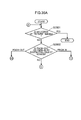
Fig. 35A is a flowchart showing a process flow for the operation terminal to generate and transmit a control command for controlling the curtain and the lace curtain of the electric curtain system in the embodiment ofFigs. 29 to 33 . -
Fig. 35B is a flowchart showing a process flow for the operation terminal to generate and transmit a control command for controlling the curtain and the lace curtain of the electric curtain system in the embodiment ofFigs. 29 to 33 . -
Fig. 35C is a flowchart showing a process flow for the operation terminal to generate and transmit a control command for controlling the curtain and the lace curtain of the electric curtain system in the embodiment ofFigs. 29 to 33 . -
Fig. 35D is a flowchart showing a process flow for the operation terminal to generate and transmit a control command for controlling the curtain and the lace curtain of the electric curtain system in the embodiment ofFigs. 29 to 33 . -
Fig. 36 is a flowchart showing a process flow in the electric curtain system in the embodiment ofFigs. 29 to 33 . -
Fig. 37 is a diagram showing a display example of the curtain control screen in which the actual position of the shade curtain is displayed when opening the shade curtain. -
Fig. 38 is a diagram showing a display example of the curtain control screen in which the actual position of the shade curtain is displayed when closing the shade curtain. -
Fig. 39 is a diagram showing a display example of the curtain control screen which is different fromFig. 37 and in which the actual position of the shade curtain is displayed when opening the shade curtain. -
Fig. 40 is a diagram showing a display example of the curtain control screen which is different fromFig. 38 and in which the actual position of the shade curtain is displayed when closing the shade curtain. -
Fig. 41A is a flowchart showing a process flow for the operation terminal to generate and transmit a control command for controlling the shade curtain of the electric curtain system in the embodiment ofFigs. 37 to 40 . -
Fig. 41B is a flowchart showing a process flow for the operation terminal to generate and transmit a control command for controlling the shade curtain of the electric curtain system in the embodiment ofFigs. 37 to 40 . -
Fig. 41C is a flowchart showing a process flow for the operation terminal to generate and transmit a control command for controlling the shade curtain of the electric curtain system in the embodiment ofFigs. 37 to 40 . -
Fig. 41D is a flowchart showing a process flow for the operation terminal to generate and transmit a control command for controlling the shade curtain of the electric curtain system in the embodiment ofFigs. 37 to 40 . -
Fig. 42 is a flowchart showing a process flow in the electric curtain system in the embodiment ofFigs. 37 to 40 . - First, the point of view of an aspect according to the present disclosure will be described.
- In
Patent Document 1 described above, in thetransmitter 21 of the wirelessremote controller 3, a user operates an operation button of an operation switch 24 to generate an operation signal for operation such as opening, closing, and stopping the curtain, and the operation signal is sent to a microcomputer 25, and thereafter converted into a radio signal to be transmitted into the atmosphere (paragraphs [0035] and [0038] andFig. 2 of Patent Document 1). When an operation signal is input to the microcomputer 25 by an operation button, a display signal generated by the microcomputer 25 in accordance with the operation signal is sent to an LED display unit 30, and the LED display unit 30 displays the operation state (paragraph [0039] andFig. 2 of Patent Document 1). - In the
receiver 22 of the wirelessremote controller 3, on the other hand, the radio signal transmitted from thetransmitter 21 is received, and converted into a digital signal. A microcomputer 45 generates a motor operation control signal and a display signal indicating operation of an electric curtain in accordance with the digital signal. The microcomputer 45 sends the motor operation control signal to the motor-side device 2, and sends the display signal to an LED display unit 50 of thereceiver 22. The LED display unit 50 displays the operation state of the electric curtain (paragraphs [0043] to [0045] andFig. 3 of Patent Document 1). - In
Patent Document 1 described above, however, thetransmitter 21 having the operation switch 24 for operation such as opening, closing, and stopping the curtain and thereceiver 22 having the LED display unit 50 which displays the operation state of the electric curtain are separate devices. Therefore, the operation state of the electric curtain cannot be confirmed at the same time while operating to open, close, or stop the curtain. As a result, if the operation state of the electric curtain is confirmed with the LED display unit 50 of thereceiver 22 which is a device that is different from thetransmitter 21 in the case where the curtain is opened and stopped at a desired position, the curtain may be stopped past the desired position because of a time lag. For example, the curtain may be opened too widely, where it is intended to open the curtain only slightly, and it may be difficult to stop opening operation of the curtain at a position intended by the user. - Thus, in
Patent Document 1 described above, the operation switch 24 provided to thetransmitter 21 and the LED display unit 50 provided to thereceiver 22 are separate members in separate devices. Therefore, the system is unsuitable for a process in which opening and closing of the electric curtain is finely adjusted. Thetransmitter 21 is provided with the LED display unit 30. However, the LED display unit 30 displays the operation state of the operation switch 24, not the operation state of the curtain. - In addition,
Patent Document 1 does not disclose at all how to operate an electric curtain and an electric lace curtain provided for an identical window, for example. For example,Patent Document 1 does not disclose at all how to operate the electric curtain and the electric lace curtain in the case where it is desired to open the electric curtain and to open the electric lace curtain successively thereafter. -
Patent Document 2 described above merely discloses a technology in which a winding shaft for the electric curtain is rotated forward to lower the curtain, or the winding shaft for the electric curtain is rotated in reverse to raise the curtain, in accordance with the sound generated by the telephone set, and does not disclose at all means for confirming the open/close state of the curtain. Therefore, it is not possible to confirm what intermediate position the curtain is actually opened or closed to, even if opening and closing of the electric curtain can be remotely operated. Thus,Patent Document 2 described above does not disclose means for confirming the open/close state of the curtain. Therefore, it is difficult to finely adjust opening and closing of the electric curtain. - In addition,
Patent Document 2 does not disclose at all how to operate an electric curtain and an electric lace curtain provided for an identical window, for example. For example,Patent Document 2 does not disclose at all how to operate the electric curtain and the electric lace curtain in the case where it is desired to open the electric curtain and to open the electric lace curtain successively thereafter. -
Patent Document 3 described above discloses an electric curtain open/close device and an electric curtain open/close method in which a plurality of curtains are individually opened to a desired position by a drive force of a single motor. In the electric curtain open/close device and the electric curtain open/close method, an open/close instruction is received from a predetermined cellular phone 24 via the Internet 23 (paragraph [0040] of Patent Document 3). The open/close instruction includes information related to which curtain is opened to what position (paragraph [0048] of Patent Document 3). - However,
Patent Document 3 does not disclose at all means for confirming the open/close state of the curtain. Therefore, it is not possible to confirm what intermediate position the curtain is actually opened or closed to, even if opening and closing of the electric curtain can be operated remotely. Thus,Patent Document 3 described above does not disclose means for confirming the open/close state of the curtain. Therefore, it is difficult to finely adjust opening and closing of the electric curtain. - In addition,
Patent Document 3 does not disclose at all how to operate an electric curtain and an electric lace curtain provided for an identical window, for example. For example,Patent Document 3 does not disclose at all how to operate the electric curtain and the electric lace curtain in the case where it is desired to open the electric curtain and to open the electric lace curtain successively thereafter. - Based on the considerations described above, the inventors have conceived various aspects of the present invention to be described below.
- A first aspect of the present disclosure is
a method for controlling an information apparatus, the information apparatus having a touch panel display and being connected to a network, an electric curtain device being controlled over the network, the electric curtain device being capable of opening and closing a curtain through remote operation,
the method causing a computer of the information apparatus to: - display an operation icon on a display screen of the information apparatus, the operation icon causing an operation screen for the electric curtain device to be displayed;
- display the operation screen for the electric curtain device when selection of the operation icon is sensed, the operation screen including a curtain image representing the curtain of the electric curtain device; and
- when a pinch-out operation is sensed on the operation screen, output to the network a first open control command for opening the curtain of the electric curtain device.
- According to the aspect, when the operation screen for the electric curtain device is displayed, a curtain image representing the curtain of the electric curtain device is included in the operation screen. Then, the curtain image included in the operation screen is utilized to sense a pinch-out operation on the curtain image, for example, on the operation screen to perform control for opening the curtain of the corresponding electric curtain device.
- This enables remotely controlling the open-close operation of the curtain of the electric curtain device which is not a device in which power is simply turned on and off.
- Open-close of the curtain of the electric curtain device is controlled through the pinch-out operation, for example, which enables the curtain of the electric curtain device to be not only opened completely but also opened halfway.
- For example, there is a case where the curtain of the electric curtain device is opened halfway and further opened or closed while confirming the opened state. Also in this case, the open/close state of the curtain of the electric curtain device can be confirmed while performing an operation (pinch-out operation) of opening the curtain of the electric curtain device on the operation screen. That is, the operation screen also serves as a confirmation screen for confirmation as to what position the curtain is opened to in accordance with an instruction given by the user by performing an operation on the operation screen. Thus, the screen for operation instruction is also used as the screen for confirmation of the open/close state. Therefore, it is possible to effectively process an operation of opening the curtain of the electric curtain device, and to make the most of the display area of the operation screen.
- Further, as described above, the operation screen also serves as display for confirmation of the open/close state of the curtain. Thus, the operation screen can be used not only to stop the curtain of the electric curtain device in the middle of being opened and closed, but also to confirm that an instruction to stop the curtain at a desired position has been given at the same time. As a result, for example, opening and closing of the curtain of the electric curtain device can be stopped without the curtain moving past the desired position. In addition, for example, the open/close position of the curtain of the electric curtain device can be finely adjusted.
- Further, in the aspect described above, when the pinch-out operation is sensed on the operation screen, display of the curtain image on the operation screen may be varied from a state in which the curtain of the electric curtain device is closed to a state in which the curtain of the electric curtain device is opened, and a lace curtain image may be displayed on the operation screen, the lace curtain image representing a lace curtain of an electric lace curtain device capable of opening and closing the lace curtain through remote operation.
- This allows an operation of opening the curtain of the electric curtain device and confirmation of the open-close state of the curtain of the electric curtain device to be performed with an identical curtain image on the operation screen. Thus, the operation screen and the confirmation screen are integral with each other. Therefore the open-close state of the curtain of the electric curtain device can be confirmed by making the most of the size of the operation screen. As a result, even an operation that needs fine adjustment such as opening the curtain of the electric curtain device halfway is enabled.
- Further, in the aspect described above, for example, when a second pinch-out operation is sensed on the operation screen, a second open control command may be output to the network, the second open control command for opening the lace curtain of the electric lace curtain device corresponding to the lace curtain image.
- Consequently, in the case where an electric curtain device and an electric lace curtain device are provided for an identical window, an operation screen for the electric curtain device and an operation screen for the electric lace curtain device are not separately displayed. In this case, an operation for the electric curtain device and an operation for the electric lace curtain device can be performed on a common operation screen. Thus, also in the case where it is desired to open the curtain of the electric curtain device and to open the lace curtain of the electric lace curtain device successively thereafter, control can be performed effectively on the common operation screen.
- Further, in the aspect described above, for example, when the second pinch-out operation is sensed on the operation screen, display of the lace curtain image on the operation screen may be varied to a state in which the lace curtain of the electric lace curtain device is opened.
- This allows an operation of opening the lace curtain of the electric lace curtain device and confirmation of the open-close state of the lace curtain of the electric lace curtain device to be performed on the operation screen for the electric curtain device as overlapped on the curtain image representing the curtain of the electric curtain device. Thus, the operation screen and the confirmation screen for the electric curtain device and the operation screen and the confirmation screen for the electric lace curtain device are integral with each other. Therefore the open-close state of the electric curtain device and the electric lace curtain device can be confirmed by making the most of the size of the operation screen.
- Further, in the aspect described above, for example, when the pinch-out operation is sensed on the operation screen, display of the curtain image on the operation screen may be varied from a state in which the curtain of the electric curtain device is closed to a state in which the curtain of the electric curtain device is opened, and when a pinch-in operation is sensed on the operation screen, a first close control command may be output to the network, the first close control command being for closing the curtain of the electric curtain device corresponding to the curtain image.
- Further, in the aspect described above, for example, when the pinch-in operation is sensed on the operation screen, display of the curtain image on the operation screen may be varied from a state in which the curtain of the electric curtain device is opened to a state in which the curtain of the electric curtain device is closed.
- Further, in the aspect described above, for example, when the pinch-out operation is sensed on the operation screen, a width control command may be output to the network as the first open control command, the width control command being for moving the curtain of the electric curtain device in accordance with an operation width of the pinch-out operation.
- Consequently, open-close of the curtain of the electric curtain device is controlled in accordance with the operation width of the pinch-out operation, for example. Therefore, the curtain of the electric curtain device may be not only opened completely but also opened halfway.
- In a second aspect of the present disclosure, for example,
a method for controlling an information apparatus, the information apparatus having a touch panel display and being connected to a network, an electric curtain device being controlled over the network, the electric curtain device being capable of opening and closing a curtain through remote operation,
the method may cause a computer of the information apparatus to: - display an operation icon on a display screen of the information apparatus, the operation icon causing an operation screen for the electric curtain device to be displayed;
- display the operation screen for the electric curtain device when selection of the operation icon is sensed, the operation screen including a curtain image representing the curtain of the electric curtain device; and
- when a pinch-in operation is sensed on the operation screen, output to the network a first close control command being for closing the curtain of the electric curtain device.
- Further, in the second aspect described above, for example, when the pinch-in operation is sensed on the operation screen, a width control command may be output to the network as the first close control command, the width control command being for moving the curtain of the electric curtain device in accordance with an operation width of the pinch-in operation.
- In any of the aspects described above, for example, the electric curtain device may include an electric blind device capable of opening or closing a blind through a remote operation.
- A third aspect of the present disclosure is
a method for controlling an information apparatus, the information apparatus having a touch panel display and being connected to a network, an electric curtain device being controlled over the network, the electric curtain device being capable of opening and closing a curtain through remote operation,
the method causing a computer of the information apparatus to: - display an operation icon on a display screen of the information apparatus, the operation icon causing an operation screen for the electric curtain device to be displayed;
- display the operation screen for the electric curtain device when selection of the operation icon is sensed, the operation screen including a curtain image representing the curtain of the electric curtain device; and
- when a swipe operation is sensed on the operation screen, output to the network a movement control command for moving the curtain of the electric curtain device in a swipe direction of the swipe operation.
- According to the aspect, when the operation screen for the electric curtain device is displayed, a curtain image representing the curtain of the electric curtain device is included in the operation screen. Then, the curtain image included in the operation screen is utilized to sense a swipe operation on the curtain image, for example, on the operation screen to perform control for moving the curtain of the electric curtain device in the swipe direction of the swipe operation.
- This enables remotely controlling the electric curtain device which is not simply turned on and off.
- Movement of the curtain of the electric curtain device is controlled through the swipe operation, for example. Therefore, the curtain of the electric curtain device may be not only opened completely but also opened halfway.
- For example, there is a case where the curtain of the electric curtain device is opened halfway and further opened or closed while confirming the opened state. Also in this case, the open/close state of the electric curtain can be confirmed while performing a moving operation of the curtain of the electric curtain device on the operation screen. That is, the operation screen also serves as a confirmation screen for confirmation as to what position the curtain is moved to in accordance with an instruction by performing an operation on the operation screen.
- Thus, the operation instruction screen and the moving state confirmation screen are common to each other. Therefore, it is possible to effectively process an operation of moving the curtain of the electric curtain device, and to make the most of the display area of the operation screen. Further, as described above, the operation screen also serves as display for confirmation of the open/close state of the curtain. Thus, the operation screen can be used not only to stop the curtain of the electric curtain device in the middle of being opened and closed, but also to confirm that an instruction to stop the curtain at a desired position has been given at the same time. As a result, for example, opening and closing of the curtain of the electric curtain device can be stopped without the curtain moving past the desired position. In addition, for example, the open/close position of the curtain of the electric curtain device can be finely adjusted.
- In the third aspect described above, for example, a distance control command may be output to the network as the movement control command when the swipe operation is sensed on the operation screen, the distance control command causing the curtain of the electric curtain device to move in the swipe direction a distance in accordance with an amount of movement in the swipe direction of the swipe operation.
- Consequently, movement of the curtain of the electric curtain device is controlled through the swipe operation. Therefore, the curtain of the electric curtain device may be not only opened completely but also opened halfway.
- In the third aspect described above, for example, movement of the curtain of the electric curtain device may be movement to open the curtain of the electric curtain device or movement to close the curtain of the electric curtain device.
- In the third aspect described above, for example, the electric curtain device may have a curtain which opens or closes in one direction.
- In the third aspect described above, for example, the electric curtain device may include an electric roll screen device, the electric roll screen device having a roll screen which opens or closes in one direction, as the curtain which opens or closes in one direction.
- In the third aspect described above, for example, the electric curtain device may include an electric blind device, the electric blind device having a blind which opens or closes in one direction, as the curtain which opens or closes in one direction.
- In the first aspect described above, for example, when the pinch-out operation is sensed on the operation screen, display of the curtain image on the operation screen may be varied from a state in which the curtain of the electric curtain device is closed to a state in which the curtain of the electric curtain device is opened, positional information indicating a position of the curtain of the electric curtain device may be received via the network, and state information representing a position of an end portion of the curtain of the electric curtain device may be displayed on the operation screen in accordance with the positional information.
- According to the aspect, state information representing the position of the end portion of the curtain of the electric curtain device is displayed on the operation screen besides a curtain image representing to what position the curtain of the electric curtain device is moved by an operation on the operation screen. For example, there may be a case where a gap is present between the position of the end of the curtain image representing the curtain of the electric curtain device in the operation screen and the actual position to which the curtain of the electric curtain device has been moved. Also in such a case, the user is allowed to recognize the presence of the gap by confirming the state information representing the position of the end portion of the curtain of the electric curtain device.
- Therefore, it is possible to prevent an erroneous recognition that the curtain of the electric curtain device is closed, even if the curtain of the electric curtain device is actually not closed yet, just by confirming display on the operation screen, the erroneous recognition being due to a gap between the moving speed of the curtain of the electric curtain device on the operation screen and the actual moving speed of the curtain of the electric curtain device, for example.
- As a result, the operation screen functions not only to represent to what position the curtain of the electric curtain device is moved by an operation of the operation screen, but also as a confirmation screen for confirmation of the actual position to which the curtain of the electric curtain device has been moved, without confirming the actual curtain of the electric curtain device. Thus, the actual position to which the curtain of the electric curtain device has been moved can be confirmed using the operation screen.
- In the aspect described above, for example,
the state information representing the position of the end portion of the curtain of the electric curtain device may be displayed on the operation screen as overlapped on the curtain image. - According to the aspect, the state information representing the position of the end portion of the curtain of the electric curtain device is displayed as overlapped on the curtain image. This allows the user to confirm the position of the end portion of the curtain of the electric curtain device with the user's eyes keeping on confirming the curtain image which is varied from a state in which the curtain of the electric curtain device is closed to a state in which the curtain of the electric curtain device is opened.
- Therefore, the actual position of the end portion of the curtain of the electric curtain device can be confirmed, while performing an operation on the operation screen, at the same time as the operation. For example, there may be a case where a gap is present between the position of the curtain image representing the curtain of the electric curtain device in the operation screen and the actual position to which the curtain of the electric curtain device has been moved. Also in such a case, it is possible to prevent an erroneous recognition that the curtain of the electric curtain device is closed even if the curtain of the electric curtain device is actually not closed yet because of failing to confirm the actual position of the end portion of the curtain of the electric curtain device.
- In the aspect described above, for example,
the state information representing the position of the end portion of the curtain of the electric curtain device may include a schematic curtain movement image representing the position of the end portion of the curtain of the electric curtain device. - According to the aspect, the schematic curtain movement image representing the position of the end portion of the curtain of the electric curtain device is displayed as overlapped on the curtain image which is varied from a state in which the curtain of the electric curtain device is closed to a state in which the curtain of the electric curtain device is opened. This allows the user to recognize a gap, if any, that is present between the curtain image representing the curtain of the electric curtain device in the operation screen and the actual position to which the curtain of the electric curtain device has been moved, for example, at a glance. Therefore, the operation screen can be used not only to perform the operation but also to confirm the operation instruction and confirm the actual position to which the curtain of the electric curtain device has been moved on the same screen.
- In the second aspect described above, for example, when the pinch-in operation is sensed on the operation screen, display of the curtain image on the operation screen may be varied from a state in which the curtain of the electric curtain device is opened to a state in which the curtain of the electric curtain device is closed, positional information indicating a position of the curtain of the electric curtain device may be received via the network; and state information representing a position of an end portion of the curtain of the electric curtain device may be displayed on the operation screen in accordance with the positional information.
- According to the aspect, state information representing the position of the end portion of the curtain of the electric curtain device is displayed on the operation screen besides a curtain image representing to what position the curtain of the electric curtain device is moved by an operation of the operation screen. For example, there may be a case where a gap is present between the position of the curtain image representing the curtain of the electric curtain device in the operation screen and the actual position to which the curtain of the electric curtain device has been moved. Also in this case, the user is allowed to recognize the presence of the gap by confirming the state information representing the position of the end portion of the curtain of the electric curtain device.
- Therefore, it is possible to prevent an erroneous recognition that the curtain of the electric curtain device is opened, even if the curtain of the electric curtain device is actually not opened yet, just by confirming display on the operation screen, the erroneous recognition being due to a gap between the moving speed of the curtain of the electric curtain device on the operation screen and the actual moving speed of the curtain of the electric curtain device, for example.
- As a result, the operation screen functions not only to represent to what position the curtain of the electric curtain device is moved by an operation of the operation screen, but also as a confirmation screen for confirmation of the actual position to which the curtain of the electric curtain device has been moved, without confirming the actual curtain of the electric curtain device. Thus, the actual position to which the curtain of the electric curtain device has been moved can be confirmed using the operation screen.
- In the aspect described above, for example,
the state information representing the position of the end portion of the curtain of the electric curtain device may be displayed on the operation screen as overlapped on the curtain image. - According to the aspect, the state information representing the position of the end portion of the curtain of the electric curtain device is displayed as overlapped on the curtain image. This allows the user to confirm the position of the end portion of the curtain of the electric curtain device with the user's eyes keeping on confirming the curtain image which is varied from a state in which the curtain of the electric curtain device is opened to a state in which the curtain of the electric curtain device is closed.
- Therefore, the actual position of the end portion of the curtain of the electric curtain device can be confirmed while performing an operation on the operation screen at the same time as the operation. For example, there may be a case where a gap is present between the curtain image representing the curtain of the electric curtain device in the operation screen and the actual position to which the curtain of the electric curtain device has been moved. Also in this case, it is possible to prevent an erroneous recognition that the curtain of the electric curtain device is opened even if the curtain of the electric curtain device is actually not opened yet because of failing to confirm the actual position of the end portion of the curtain of the electric curtain device.
- In the aspect described above, for example,
the state information representing the position of the end portion of the curtain of the electric curtain device may include a schematic curtain movement image representing the position of the end portion of the curtain of the electric curtain device. - According to the aspect, a schematic curtain movement image representing the position of the end portion of the curtain of the electric curtain device is displayed as overlapped on the curtain image which is varied from a state in which the curtain of the electric curtain device is opened to a state in which the curtain of the electric curtain device is closed. This allows the user to recognize a gap, if any, that is present between the curtain image representing the curtain of the electric curtain device in the operation screen and the actual position to which the shutter of the electric shutter device has been moved, for example, at a glance. Therefore, the operation screen can be used not only to perform the operation but also to confirm the operation instruction and confirm the actual position to which the curtain of the electric curtain device has been moved on the same screen.
- In the third aspect described above, for example,
when the swipe operation is sensed on the operation screen, display of the curtain image on the operation screen may be varied to an image representing movement of the curtain of the electric lace curtain device,
positional information indicating a position of the curtain of the electric curtain device may be received via the network, and
state information representing a position of an end portion of the curtain of the electric curtain device may be displayed on the operation screen in accordance with the positional information. - According to the aspect, state information representing the position of the end portion of the curtain of the electric curtain device is displayed on the operation screen besides a curtain image representing to what position the curtain of the electric curtain device is moved by an operation of the operation screen. For example, there may be a case where a gap is present between the curtain image representing the curtain of the electric curtain device in the operation screen and the actual position to which the curtain of the electric curtain device has been moved. Also in this case, the user is allowed to recognize the presence of the gap by confirming the state information representing the position of the end portion of the curtain of the electric curtain device.
- Therefore, it is possible to prevent an erroneous recognition that the curtain of the electric curtain device is closed, even if the curtain of the electric curtain device is actually not closed yet, for example, just by confirming display on the operation screen, the erroneous recognition being due to a gap between the moving speed of the curtain of the electric curtain device on the operation screen and the actual moving speed of the curtain of the electric curtain device, for example.
- As a result, the operation screen functions not only to represent to what position the curtain of the electric curtain device is moved by an operation of the operation screen, but also as a confirmation screen for confirmation of the actual position to which the curtain of the electric curtain device has been moved, without confirming the actual curtain of the electric curtain device. Thus, the actual position to which the curtain of the electric curtain device has been moved can be confirmed using the operation screen.
- In the aspect described above, for example,
the state information representing the position of the end portion of the curtain of the electric curtain device may be displayed on the operation screen as overlapped on the image representing movement of the curtain of the electric curtain device. - According to the aspect, the state information representing the position of the end portion of the curtain of the electric curtain device is displayed as overlapped on the image representing movement of the curtain of the electric curtain device. This allows the user to confirm the position of the end portion of the curtain of the electric curtain device with the user's eyes keeping on confirming the image representing movement of the curtain of the electric curtain device.
- Therefore, the actual position of the end portion of the curtain of the electric curtain device can be confirmed while performing an operation on the operation screen at the same time as the operation. For example, there may be an occasion where a gap is present between the curtain image representing the curtain of the electric curtain device in the operation screen and the actual position to which the curtain of the electric curtain device has been moved. Also in this case, it is possible to prevent an erroneous recognition that the curtain of the electric curtain device is opened even if the curtain of the electric curtain device is actually not opened yet because of failing to confirm the actual position of the end portion of the curtain of the electric curtain device.
- In the aspect described above, for example,
the state information representing the position of the end portion of the curtain of the electric curtain device may include a schematic curtain movement image representing the position of the end portion of the curtain of the electric curtain device. - According to the aspect, the schematic curtain movement image representing the position of the end portion of the curtain of the electric curtain device is displayed as overlapped on the image representing movement of the curtain of the electric curtain device. This allows the user to recognize a gap, if any, that is present between the curtain image representing the curtain of the electric curtain device in the operation screen and the actual position to which the curtain of the electric curtain device has been moved, for example, at a glance. Therefore, the operation screen can be used not only to perform the operation but also to confirm the operation instruction and confirm the actual position to which the curtain of the electric curtain device has been moved on the same screen.
- An embodiment of the present disclosure will be described below with reference to the drawings. In the drawings, the same symbols are used for the same constituent elements.
- In the embodiment, an operation terminal which can remotely control curtain will be described.
-
Fig. 1 is a diagram showing an overall configuration of a curtain control system according to the embodiment. As shown inFig. 1 , the curtain control system includes anoperation terminal 100, andelectric curtain systems - The
operation terminal 100 and theelectric curtain systems operation terminal 100 and theelectric curtain systems wireless network 300. For example, theelectric curtain systems operation terminal 100 are communicably connected to each other via the wireless or wired in-home network 300. Thenetwork 300 may be an external network such as the Internet. - The
operation terminal 100 is not necessarily disposed in the house, and may be disposed outside the house. In this case, a user controls theelectric curtain systems - An information terminal such as a smartphone or a tablet terminal may be adopted as the
operation terminal 100. It should be noted, however, that the smartphone and the tablet terminal are merely exemplary, and an information terminal of a button type such as a cellular phone may be adopted as theoperation terminal 100. - In the embodiment, as shown in
Fig. 1 , threeelectric curtain systems -
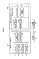
Fig. 2 is a block diagram showing the electrical configuration of theoperation terminal 100 and theelectric curtain systems Fig. 3 is a diagram schematically showing the configuration of theelectric curtain system 200. As shown inFig. 2 , theoperation terminal 100 includes adisplay 101, a touchpanel control section 102, adisplay control section 103, astorage section 104, acurtain control section 105, and acommunication control section 106. - The
display 101 is formed from a touch panel display, for example, and displays a user interface that allows the user to operate theoperation terminal 100. The user can input various operations to theoperation terminal 100 by contacting thedisplay 101. - The touch
panel control section 102 recognizes an operation performed on thedisplay 101 by the user, interprets the content of the operation, and notifies the other constituent elements of the content of the operation. For example, if an object is displayed at a position on thedisplay 101 tapped on by the user, the touchpanel control section 102 judges that the object is selected by the user. A variety of GUI (Graphical User Interface) parts that receive a user operation such as buttons are adopted as the object. - The
display control section 103 generates a GUI of theoperation terminal 100, and causes thedisplay 101 to display the GUI. Thestorage section 104 stores information that is necessary for operation of theoperation terminal 100 such as the type and the arrangement of the curtain which is the operation target. - The
curtain control section 105 generates a control command for each of theelectric curtain systems communication control section 106 controls communication between theoperation terminal 100 and theelectric curtain systems communication control section 106 receives a request to transmit a variety of data from other blocks such as thecurtain control section 105, and transmits the received data to theelectric curtain systems communication control section 106 receives data transmitted from theelectric curtain systems curtain control section 105. - The
display 101 may be a normal display rather than a touch panel display. In this case, the user may use an external input device such as a mouse (not shown) to input an instruction to select an object by moving a pointer displayed on thedisplay 101 and clicking on a desired object. That is, in the embodiment, a series of operations performed by the user by contacting thedisplay 101 may be replaced with operations of moving a pointer and clicking using an external input device such as a mouse. - As shown in
Fig. 3 , theelectric curtain system 200 includes acontrol unit 210, a thick curtain (hereinafter referred to simply as a "curtain") 221, athin lace curtain 222, and so forth. Theelectric curtain system 200 includes an electric curtain device capable of electrically opening and closing thecurtain 221 through remote operation, and an electric lace curtain device capable of electrically opening and closing thelace curtain 222 through remote operation. - As shown in
Fig. 2 , thecontrol unit 210 includes adrive section 211, aposition sensor 212, acurtain control section 213, and acommunication control section 214. Thedrive section 211 includes a motor capable of rotating is forward and reverse directions, for example, to open and close thecurtain 221 and thelace curtain 222. - The
position sensor 212 detects the open/close state (position) of thecurtain 221 and thelace curtain 222. Theposition sensor 212 specifically detects the position of an end portion on the moving side of thecurtain 221 and thelace curtain 222, for example, as the open/close state of thecurtain 221 and thelace curtain 222. - The
position sensor 212 includes an encoder attached to a rotary shaft of the motor of thedrive section 211 coupled to thecurtain 221 or thelace curtain 222, for example. In this case, theposition sensor 212 detects the open/close state of thecurtain 221 in the case where the rotary shaft of the motor of thedrive section 211 is coupled to thecurtain 221, and detects the open/close state of thelace curtain 222 in the case where the rotary shaft of the motor of thedrive section 211 is coupled to thelace curtain 222. - Alternatively, the
position sensor 212 may count the number of steps of a stepping motor driven when opening and closing thecurtain 221 and thelace curtain 222 in the case where thedrive section 211 includes a stepping motor. Theposition sensor 212 may be any unit that can detect the open/close state of thecurtain 221 and thelace curtain 222. - The
curtain control section 213 controls opening and closing of thecurtain 221 and thelace curtain 222 of theelectric curtain system 200 in accordance with a control command transmitted from theoperation terminal 100. In addition, thecurtain control section 213 requests thecommunication control section 214 to transmit the result of execution of the control command, the open/close state of thecurtain 221 and thelace curtain 222 of theelectric curtain system 200, and so forth to theoperation terminal 100. - The
communication control section 214 controls communication between theelectric curtain system 200 and theoperation terminal 100. In addition, thecommunication control section 214 receives a request to transmit a variety of data from thecurtain control section 213, and transmits such data to theoperation terminal 100. Thecommunication control section 214 receives data transmitted from theoperation terminal 100, and delivers the data to thecurtain control section 213. - The
electric curtain systems electric curtain system 200 shown inFig. 2 . Theelectric curtain system 200 is disposed in a living room, for example. Theelectric curtain system 201 is disposed in a bedroom, for example. Theelectric curtain system 202 is disposed in a child room, for example. -
Fig. 4 is a diagram showing a configuration example of the form of implementation of theoperation terminal 100. As shown inFig. 4 , theoperation terminal 100 includes anapplication 401, an OS (Operating System) 402, amemory 403, and other hardware (not shown). - The
application 401 is application software for causing the information terminal to function as theoperation terminal 100, and is executed by a processor of theoperation terminal 100. Theoperation terminal 100 may read theapplication 401 from a computer readable recording medium to implement theapplication 401, or may download theapplication 401 from a network to implement theapplication 401. TheOS 402 is basic software of the information terminal, and is executed by the processor of theoperation terminal 100. Thememory 403 is formed from a storage device such as a RAM and a ROM of theoperation terminal 100, and stores a group of data included in theapplication 401. The processor of theoperation terminal 100 executes theapplication 401 to embody the functions of the touchpanel control section 102, thedisplay control section 103, thestorage section 104, thecurtain control section 105, and thecommunication control section 106 shown inFig. 2 . In addition, the processor of theoperation terminal 100 executes theapplication 401 to cause thememory 403 to function as thestorage section 104. - It should be noted, however, that in the embodiment, the
operation terminal 100 may be implemented by theapplication 401 alone, may be implemented by theapplication 401 and theOS 402, may be implemented by theapplication 401, theOS 402, and thememory 403, or may be implemented by theapplication 401, theOS 402, thememory 403, and other hardware (not shown). In any embodiment, theoperation terminal 100 according to the embodiment can be embodied. In the embodiment, the processor and the storage device forming the information terminal, for example, form a computer. One of a CPU, an FPGA, and an ASIC or a combination of two or more of these may be adopted as the processor. One of a ROM, a RAM, and a hard disk or a combination of two or more of these may be adopted as the storage device. -
Fig. 5 is a diagram showing a display example of a menu screen displayed on thedisplay 101 for a case where a tablet is used as theoperation terminal 100.Fig. 6 is a diagram showing a display example of a menu screen displayed on thedisplay 101 for a case where a smartphone is used as theoperation terminal 100. As shown inFigs. 5 and6 , the menu screen displayed on thedisplay 101 of theoperation terminal 100 includes acurtain icon 111. Thecurtain icon 111 is an operation icon for starting theapplication 401 for electric curtain control. Thecurtain icon 111 includes an image schematically representing a curtain. -
Fig. 7 is a diagram showing an example of a curtainselect screen 400 displayed on thedisplay 101 of theoperation terminal 100. When the user selects thecurtain icon 111 with a contacting object (for example, one finger of the user) in the menu screen shown inFig. 5 or6 , the touchpanel control section 102 senses the selection. Then, theapplication 401 for electric curtain control is started, and thedisplay control section 103 displays the curtainselect screen 400 corresponding to thecurtain icon 111 on thedisplay 101 as shown inFig. 7 . - The curtain
select screen 400 includesselect buttons set button 406, and anend button 407. A text "SELECT CURTAIN" is affixed to the curtainselect screen 400. The configuration allows the user to easily understand that the screen displayed on thedisplay 101 is a screen for selecting an electric curtain system. - The
select button 405A is an operation button for selecting theelectric curtain system 200 in the living room. Theselect button 405B is an operation button for selecting theelectric curtain system 201 in the bedroom. Theselect button 405C is an operation button for selecting theelectric curtain system 202 in the child room. Theselect buttons electric curtain systems - The
set button 406 is an operation button for making a variety of settings. Theset button 406 is used to associate a select button and a curtain as the operation target with each other, for example. Theset button 406 is used to set the type of an electric curtain system such as a double type provided with a curtain and a lace curtain, a shade curtain type, a roll screen type, a blind type, a center draw type, and a one-way draw type, for example. Theset button 406 is used to set a name given to a select button, for example. - The
end button 407 is an operation button for ending theapplication 401 for electric curtain control. When the user selects theend button 407 with a contacting object (for example, one finger of the user), the touchpanel control section 102 senses the selection. Then, theapplication 401 for electric curtain control is ended, and thedisplay control section 103 restores a state in which the menu screen is displayed on thedisplay 101 as shown inFig. 5 or6 . -
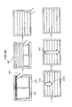
Fig. 8 is a diagram showing an example of acurtain control screen 410 displayed on thedisplay 101 of theoperation terminal 100. Thecurtain control screen 410 shown inFig. 8 is an operation screen that allows performing an open/close operation for thecurtain 221 of the electric curtain device and thelace curtain 222 of the electric lace curtain device included in theelectric curtain system 200 disposed in the living room. - The
curtain control screen 410 includes areturn button 411, acurtain image 412 representing thecurtain 221 of the electric curtain device, and a lace curtain image 413 (Figs. 9 to 12 ) representing thelace curtain 222 of the electric lace curtain device. In addition, a text saying "LIVING ROOM CURTAIN" is affixed to thecurtain control screen 410 ofFig. 8 . This allows the user to easily understand that the screen is a control screen for a curtain disposed in the living room. - When the user selects the
select button 405A with a contacting object (for example, one finger of the user) in the curtainselect screen 400 shown inFig. 7 , the touchpanel control section 102 senses the selection. Then, as shown inFig. 8 , thedisplay control section 103 displays thecurtain control screen 410 corresponding to theselect button 405A on thedisplay 101. - Meanwhile, when the user selects the
return button 411 with the contacting object in thecurtain control screen 410 shown inFig. 8 , the touchpanel control section 102 senses the selection. Then, thedisplay control section 103 returns the display on thedisplay 101 to the curtainselect screen 400 shown inFig. 7 . -
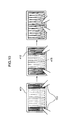
Figs. 9 and10 are each a diagram showing an example of display on thecurtain control screen 410 and an example of an operation by the contactingobject 150 during an open/close operation for the curtain.Fig. 9 shows a display example and an operation example at the time when opening thecurtain 221.Fig. 10 shows a display example and an operation example at the time when closing thecurtain 221. - First, an operation of opening the
curtain 221 of the electric curtain device of theelectric curtain system 200 will be described with reference toFig. 9 . Thecurtain image 412 representing a state in which thecurtain 221 is closed is displayed on the curtain control screen 410 (the left diagram ofFig. 9 ). In this state, the touchpanel control section 102 senses a pinch-out operation by the contacting object 150 (for example, two fingers of the user) on the curtain control screen 410 (in the order of the left diagram, the middle diagram, and the right diagram ofFig. 9 ). Then, thedisplay control section 103 varies thecurtain image 412 from the state with a closed curtain into a state with an opened curtain in accordance with movement of the contacting object 150 (in the order of the left diagram, the middle diagram, and the right diagram ofFig. 9 ). - At this time, the
display control section 103 displays thelace curtain image 413 representing a state in which thelace curtain 222 is closed as thecurtain image 412 is opened. Thecurtain control section 105 generates a control command (corresponding to an example of the first open control command) for opening thecurtain 221 of the electric curtain device of theelectric curtain system 200 corresponding to thecurtain image 412. - In addition, the
display control section 103 displays thecurtain image 412 which is opened by a width corresponding to the operation width of the pinch-out operation by the contactingobject 150. In addition, thecurtain control section 105 generates a control command (corresponding to an example of the width control command) for opening thecurtain 221 of the electric curtain device of theelectric curtain system 200 by a width corresponding to the operation width of the pinch-out operation by the contactingobject 150. - The
communication control section 106 transmits the generated control command to thecontrol unit 210 of theelectric curtain system 200. - Next, an operation of closing the
curtain 221 of the electric curtain device of theelectric curtain system 200 will be described with reference toFig. 10 . Thecurtain image 412 representing a state in which thecurtain 221 is opened and thelace curtain image 413 representing a state in which the lace curtain is closed are displayed on the curtain control screen 410 (the left diagram ofFig. 10 ). In this state, the touchpanel control section 102 senses a pinch-in operation by the contactingobject 150 on the curtain control screen 410 (in the order of the left diagram, the middle diagram, and the right diagram ofFig. 10 ). - Then, the
display control section 103 varies thecurtain image 412 from the state with an opened curtain into a state with a closed curtain in accordance with movement of the contacting object 150 (in the order of the left diagram, the middle diagram, and the right diagram ofFig. 10 ). Thecurtain control section 105 generates a control command (corresponding to an example of the first close control command) for closing thecurtain 221 of the electric curtain device of theelectric curtain system 200 corresponding to thecurtain image 412. - In addition, the
display control section 103 displays thecurtain image 412 which is opened by a width corresponding to the operation width of the pinch-in operation by the contactingobject 150. In addition, thecurtain control section 105 generates a control command (corresponding to an example of the width control command) for closing thecurtain 221 of the electric curtain device of theelectric curtain system 200 by a width corresponding to the operation width of the pinch-in operation by the contactingobject 150. - The
communication control section 106 transmits the generated control command to thecontrol unit 210 of theelectric curtain system 200. -
Figs. 11 and12 are each a diagram showing an example of display on thecurtain control screen 410 and an example of an operation by the contactingobject 150 during an open/close operation for the lace curtain.Fig. 11 shows a display example and an operation example at the time when opening thelace curtain 222.Fig. 12 shows a display example and an operation example at the time when closing thelace curtain 222. - First, an operation of opening the
lace curtain 222 of the electric lace curtain device of theelectric curtain system 200 will be described with reference toFig. 11 . Thecurtain image 412 representing a state in which thecurtain 221 is opened and thelace curtain image 413 representing a state in which thelace curtain 222 is closed are displayed (the left diagram ofFig. 11 ). In this state, the touchpanel control section 102 senses a pinch-out operation by the contactingobject 150 on the curtain control screen 410 (in the order of the left diagram, the middle diagram, and the right diagram ofFig. 11 ). Then, thedisplay control section 103 varies thelace curtain image 413 from the state with a closed lace curtain into a state with an opened lace curtain in accordance with movement of the contacting object 150 (in the order of the left diagram, the middle diagram, and the right diagram ofFig. 11 ). - At this time, the
display control section 103 displays awindow frame image 414 that represents a window frame as thelace curtain image 413 is opened. In order to achieve this, for example, thecurtain image 412 may be provided in a first layer, thelace curtain image 413 may be provided in a second layer, thewindow frame image 414 may be provided in a third layer, the order of priority for image display of the first layer may be the highest, the order of priority for image display of the second layer may be the second highest, and the order of priority for image display of the third layer may be the lowest. Thecurtain control section 105 generates a control command (corresponding to an example of the second open control command) for opening the lace curtain of the electric lace curtain device of theelectric curtain system 200 corresponding to thelace curtain image 413. - In addition, the
display control section 103 displays thelace curtain image 413 which is opened by a width corresponding to the operation width of the pinch-out operation by the contactingobject 150. In addition, thecurtain control section 105 generates a control command for opening thelace curtain 222 of the electric lace curtain device of theelectric curtain system 200 by a width corresponding to the operation width of the pinch-out operation by the contactingobject 150. - The
communication control section 106 transmits the generated control command to thecontrol unit 210 of theelectric curtain system 200. - Next, an operation of closing the
lace curtain 222 of the electric lace curtain device of theelectric curtain system 200 will be described with reference toFig. 12 . Thecurtain image 412 representing a state in which thecurtain 221 is opened and thelace curtain image 413 representing a state in which thelace curtain 222 is opened are displayed (the left diagram ofFig. 12 ). In this state, the touchpanel control section 102 senses a pinch-in operation by the contactingobject 150 on the curtain control screen 410 (in the order of the left diagram, the middle diagram, and the right diagram ofFig. 12 ). - Then, the
display control section 103 varies thelace curtain image 413 from the state with an opened lace curtain into a state with a closed lace curtain in accordance with movement of the contacting object 150 (in the order of the left diagram, the middle diagram, and the right diagram ofFig. 12 ). Thecurtain control section 105 generates a control command for closing thelace curtain 222 of the electric lace curtain device of theelectric curtain system 200 corresponding to thelace curtain image 413. - In addition, the
display control section 103 displays thelace curtain image 413 which is closed by a width corresponding to the operation width of the pinch-in operation by the contactingobject 150. In addition, thecurtain control section 105 generates a control command for closing thelace curtain 222 of the electric lace curtain device of theelectric curtain system 200 by a width corresponding to the operation width of the pinch-in operation by the contactingobject 150. - The
communication control section 106 transmits the generated control command to thecontrol unit 210 of theelectric curtain system 200. -
Fig. 13 is a sequence diagram showing a process flow in theoperation terminal 100 and theelectric curtain system 200. First, upon receiving a request from thedisplay control section 103, thecommunication control section 106 of theoperation terminal 100 transmits a request to acquire the present open/close state of thecurtain 221 and the lace curtain 222 (for example, the position of an end portion on the moving side of thecurtain 221 and the lace curtain 222) to the electric curtain system 200 (S1301). Next, when the acquisition request is received via thecommunication control section 214, thecurtain control section 213 of theelectric curtain system 200 acquires the open/close state of thecurtain 221 and thelace curtain 222 from the position sensor 212 (S1302). - Upon receiving a request from the
curtain control section 213, thecommunication control section 214 transmits the open/close state of thecurtain 221 and thelace curtain 222 to the operation terminal 100 (S1303). Thedisplay control section 103 of theoperation terminal 100 receives the open/close state of thecurtain 221 and thelace curtain 222 via thecommunication control section 106. Thedisplay control section 103 displays thecurtain control screen 410 on thedisplay 101 on the basis of the received open/close state of thecurtain 221 and the lace curtain 222 (S1304). For example, in the case where thecurtain 221 is fully open and thelace curtain 222 is fully closed, thedisplay control section 103 displays thecurtain control screen 410 shown in the left diagram ofFig. 10 on thedisplay 101. - Next, the touch
panel control section 102 of theoperation terminal 100 senses an operation (for example, a pinch-out operation, a pinch-in operation, or a swipe operation) of the contactingobject 150 performed by the user on the curtain control screen 410 (S1305). Next, thedisplay control section 103 of theoperation terminal 100 varies thecurtain image 412 or thelace curtain image 413 so as to represent the target position for opening and closing of thecurtain 221 or thelace curtain 222 in accordance with the operation width of the contacting object 150 (S1306). - In the
operation terminal 100, S1305 and S1306 included in L1301 are repeated until the touchpanel control section 102 senses that the contactingobject 150 is moved away from thedisplay 101. As a result, after a pinch-in operation is performed for half an operation width for fully closing thecurtain 221 with thecurtain control screen 410 shown in the left diagram ofFig. 10 displayed on thedisplay 101, for example, the contactingobject 150 is moved away from thedisplay 101. Then, thedisplay control section 103 displays thecurtain control screen 410 shown in the middle diagram ofFig. 10 on thedisplay 101. That is, the position of thecurtain image 412 shown in the middle diagram ofFig. 10 is determined as the target position for opening and closing of thecurtain 221. - In addition, after a pinch-in operation is performed for an operation width for fully closing the
curtain 221 with thecurtain control screen 410 shown in the left diagram ofFig. 10 displayed on thedisplay 101, for example, the contactingobject 150 is moved away from thedisplay 101. Then, thedisplay control section 103 displays thecurtain control screen 410 shown in the right diagram ofFig. 10 on thedisplay 101. That is, the position of thecurtain image 412 shown in the right diagram ofFig. 10 is determined as the target position for opening and closing of thecurtain 221. - When the touch
panel control section 102 senses that the contactingobject 150 is moved away from thedisplay 101, thecurtain control section 105 of theoperation terminal 100 generates a control command in accordance with the operation width of the contactingobject 150. Upon receiving a request from thecurtain control section 105, thecommunication control section 106 transmits the control command generated by thecurtain control section 105 to the electric curtain system 200 (S1307). - After receiving the control command via the
communication control section 214 of theelectric curtain system 200, thecurtain control section 213 controls thedrive section 211 on the basis of the control command to perform opening operation or closing operation of thecurtain 221 or the lace curtain 222 (S1308). Next, thecurtain control section 213 detects the current open/close state of thecurtain 221 or the lace curtain 222 (for example, the current position of an end portion on the moving side of thecurtain 221 or the lace curtain 222) using the position sensor 212 (S1309). - In the
electric curtain system 200, S1308 and S1309 included in L1302 are repeated until the open/close state of thecurtain 221 or thelace curtain 222 reaches the target position. When the open/close state of thecurtain 221 or thelace curtain 222 reaches the target position, thecommunication control section 214 receives a request from thecurtain control section 213, and transmits the result of control for thecurtain 221 or thelace curtain 222 to the operation terminal 100 (S1310). The process is thus terminated. -
Fig. 14 is a flowchart showing a process flow for theoperation terminal 100 to control theelectric curtain system 200. - First, the
display control section 103 displays the curtainselect screen 400 on the display 101 (S1401). Subsequently, a user operation through contact of the contactingobject 150 on the curtainselect screen 400 is received (S1402). Next, the touchpanel control section 102 judges whether or not the contact target for the contactingobject 150 is the end button 407 (S1403). - When the touch
panel control section 102 judges that the contact target is the end button 407 (YES in S1403), the flow is terminated. When the touchpanel control section 102 judges that the contact target is not the end button 407 (NO in S1403), on the other hand, the touchpanel control section 102 judges a select button of the contact target. Thedisplay control section 103 acquires the current open/close state of a curtain corresponding to the judged select button from the electric curtain system (S1404). For example, if the touchpanel control section 102 judges that the contact target is theselect button 405A, thedisplay control section 103 acquires the open/close state of thecurtain 221 and thelace curtain 222 from theelectric curtain system 200. - Next, the
display control section 103 displays a curtain control screen corresponding to the select button of the contact target on the display 101 (S1405). For example, in the case where the contact target is theselect button 405A, thedisplay control section 103 displays thecurtain control screen 410 shown inFig. 8 on thedisplay 101. Subsequently, the process is advanced to a control flow for a curtain (Figs. 15A to 15D ) (S1406). After that, the process returns to S1401. -
Figs. 15A to 15D are flowcharts showing a flow of the process (S1406 ofFig. 14 ) for theoperation terminal 100 to generate and transmit a control command for controlling thecurtain 221 and thelace curtain 222 of theelectric curtain system 200. - First, the touch
panel control section 102 judges whether or not selection of thereturn button 411 by the contactingobject 150 is sensed in the curtain control screen 410 (S1501). When selection of thereturn button 411 is sensed (YES in S1501), the flow is terminated. If selection of thereturn button 411 is not sensed (NO in S1501), the touchpanel control section 102 judges whether or not a pinch-out operation or a pinch-in operation by the contactingobject 150 is sensed (S1502). - If the touch
panel control section 102 senses a pinch-out operation in S1502, the process is advanced to S1503. If the touchpanel control section 102 senses a pinch-in operation, the process is advanced to S1511. Otherwise (NO in S1502), the process returns to S1501. - In S1503, the
display control section 103 judges, on the basis of the open/close state acquired in S1404 ofFig. 14 , whether or not thecurtain 221 of the electric curtain device of theelectric curtain system 200 is fully open. If thecurtain 221 is not fully open (NO in S1503), thecurtain image 412 displayed on thedisplay 101 is varied so as to represent the target position for opening and closing of thecurtain 221 in accordance with the operation width of the pinch-out operation acquired from the touch panel control section 102 (S1504). - Next, the
display control section 103 judges whether or not the pinch-out operation is terminated (S1505). If the pinch-out operation is not terminated (NO in S1505), the process returns to S1504. If the pinch-out operation is terminated in S1505 (YES in S1505), on the other hand, the process is advanced to S1521. Thus, S1504 is executed until the pinch-out operation is terminated. As a result, thecurtain image 412 displayed on thedisplay 101 is updated each time S1504 is executed (for example, at intervals of 0.1 seconds). Thecurtain image 412 between the left diagram and the middle diagram ofFig. 9 and thecurtain image 412 between the middle diagram and the right diagram ofFig. 9 are not shown. - If the
curtain 221 is fully open in S1503 (YES in S1503), thedisplay control section 103 judges, on the basis of the open/close state acquired in S1404 ofFig. 14 , whether or not thelace curtain 222 of the electric lace curtain device of theelectric curtain system 200 is fully open (S11506). If thelace curtain 222 is fully open (YES in S1506), the process returns to S1501. - If the
lace curtain 222 is not fully open in S1506 (NO in S1506), on the other hand, thelace curtain image 413 displayed on thedisplay 101 is varied so as to represent the target position for opening and closing of thelace curtain 222 in accordance with the operation width of the pinch-out operation acquired from the touch panel control section 102 (S1507). - Next, the
display control section 103 judges whether or not the pinch-out operation is terminated (S1508). If the pinch-out operation is not terminated (NO in S1508), the process returns to S1507. If the pinch-out operation is terminated in S1508 (YES in S1508), on the other hand, the process is advanced to S1521. Thus, S1507 is executed until the pinch-out operation is terminated. As a result, thelace curtain image 413 displayed on thedisplay 101 is updated each time S1507 is executed (for example, at intervals of 0.1 seconds). Thelace curtain image 413 between the left diagram and the middle diagram ofFig. 11 and thelace curtain image 413 between the middle diagram and the right diagram ofFig. 11 are not shown. - In S1511, the
display control section 103 judges, on the basis of the open/close state acquired in S1404 ofFig. 14 , whether or not thelace curtain 222 of the electric lace curtain device of theelectric curtain system 200 is fully closed. If thelace curtain 222 is not fully closed (NO in S1511), thelace curtain image 413 displayed on thedisplay 101 is varied so as to represent the target position for opening and closing of thelace curtain 222 in accordance with the operation width of the pinch-in operation acquired from the touch panel control section 102 (S1512). - Next, the
display control section 103 judges whether or not the pinch-in operation is terminated (S1513). If the pinch-in operation is not terminated (NO in S1513), the process returns to S1512. If the pinch-in operation is terminated in S 1513 (YES in S1513), on the other hand, the process is advanced to S1521. Thus, S1512 is executed until the pinch-in operation is terminated. As a result, thelace curtain image 413 displayed on thedisplay 101 is updated each time S1512 is executed (for example, at intervals of 0.1 seconds). Thelace curtain image 413 between the left diagram and the middle diagram ofFig. 12 and thelace curtain image 413 between the middle diagram and the right diagram ofFig. 12 are not shown. - If the
lace curtain 222 is fully closed in S1511 (YES in S1511), thedisplay control section 103 judges, on the basis of the open/close state acquired in S1404 ofFig. 14 , whether or not thecurtain 221 of the electric curtain device of theelectric curtain system 200 is fully closed (S1514). If thecurtain 221 is fully closed (YES in S1514), the process returns to S1501. - If the
curtain 221 is not fully closed in S1514 (NO in S1514), on the other hand, thecurtain image 412 displayed on thedisplay 101 is varied so as to represent the target position for opening and closing of thecurtain 221 in accordance with the operation width of the pinch-in operation acquired from the touch panel control section 102 (S1515). - Next, the
display control section 103 judges whether or not the pinch-in operation is terminated (S1516). If the pinch-in operation is not terminated (NO in S1516), the process returns to S1515. If the pinch-in operation is terminated in S1516 (YES in S1516), on the other hand, the process is advanced to S1521. Thus, S1515 is executed until the pinch-in operation is terminated. As a result, thecurtain image 412 displayed on thedisplay 101 is updated each time S1515 is executed (for example, at intervals of 0.1 seconds). Thecurtain image 412 between the left diagram and the middle diagram ofFig. 10 and thecurtain image 412 between the middle diagram and the right diagram ofFig. 10 are not shown. - In S1521, the
curtain control section 105 generates a control command for opening and closing thecurtain 221 or thelace curtain 222 up to the target position corresponding to the operation width of the pinch-out operation or the pinch-in operation acquired from the touchpanel control section 102. Subsequently, thecommunication control section 106 transmits the control command generated by thecurtain control section 105 to the electric curtain system 200 (S1522). Next, thecommunication control section 106 receives the result of control for thecurtain 221 or thelace curtain 222 transmitted from theelectric curtain system 200, and delivers the received control result to the curtain control section 105 (S1523). The flow is thus terminated. -
Fig. 16 is a flowchart showing a process flow in theelectric curtain system 200. First, thecommunication control section 214 of theelectric curtain system 200 receives a control command for opening and closing a curtain transmitted from theoperation terminal 100, and delivers the control command to the curtain control section 213 (S1601). Then, thecurtain control section 213 controls thedrive section 211 in accordance with the received control command to drive thecurtain 221 or the lace curtain 222 (S1602). Next, thecurtain control section 213 acquires the result of detection of the open/close state of thecurtain 221 or thelace curtain 222 from the position sensor 212 (S1603). - Subsequently, the
curtain control section 213 judges, on the basis of the acquired detection result, whether or not thecurtain 221 or thelace curtain 222 has reached the target position indicated by the control command (S1604). If thecurtain 221 or thelace curtain 222 has not reached the target position (NO in S1604), the process returns to S1602. If thecurtain 221 or thelace curtain 222 has reached the target position in S1604 (YES in S1604), on the other hand, thecommunication control section 214 receives a request from thecurtain control section 213, and transmits the control result to the operation terminal 100 (S1605). The flow is thus terminated. -
Fig. 17 is a diagram showing an example of thecurtain control screen 410 displayed on thedisplay 101 of theoperation terminal 100, the example being different from the curtain control screen ofFig. 8 . - The
curtain control screen 410 ofFig. 17 is an operation screen that allows performing an open/close operation for a thick shade curtain (hereinafter referred to simply as a "shade curtain") of the electric curtain device and a thin shade lace curtain of the electric lace curtain device included in theelectric curtain system 201 disposed in the bedroom. - The
curtain control screen 410 includes areturn button 411, acurtain image 421 representing the shade curtain of the electric curtain device, and a lace curtain image (not shown) representing the shade lace curtain of the electric lace curtain device. In addition, a text saying "BEDROOM CURTAIN" is affixed to thecurtain control screen 410 ofFig. 17 . This allows the user to easily understand that the screen is a control screen for a curtain disposed in the bedroom. The shade curtain is an example of the curtain that opens and closes in one direction, and opens and closes in the vertical direction. - When the user selects the
select button 405B with the contacting object in the curtainselect screen 400 shown inFig. 7 , the touchpanel control section 102 senses the selection. Then, as shown inFig. 17 , thedisplay control section 103 displays thecurtain control screen 410 corresponding to theselect button 405B on thedisplay 101. -
Figs. 18 and19 are each a diagram showing an example of an operation by the contacting object and an example of display of thecurtain control screen 410 during open/close control for the shade curtain.Fig. 18 shows an operation example and a display example at the time when opening the shade curtain.Fig. 19 shows an operation example and a display example at the time when closing the shade curtain. InFigs. 18 and19 , the lace curtain image representing the shade lace curtain is not shown. - First, an operation of opening the shade curtain of the electric curtain device of the
electric curtain system 201 will be described with reference toFig. 18 . Thecurtain image 421 in which the shade curtain is closed is displayed (the left diagram ofFig. 18 ). In this state, the touchpanel control section 102 senses an upward swipe operation by the contacting object 150 (for example, one finger of the user) on the curtain control screen 410 (in the order of the left diagram, the middle diagram, and the right diagram ofFig. 18 ). - Then, the
display control section 103 varies thecurtain image 421 from the state with a closed shade curtain into a state with an opened shade curtain in accordance with movement of the contacting object 150 (in the order of the left diagram, the middle diagram, and the right diagram ofFig. 18 ). At this time, thedisplay control section 103 displays awindow frame image 414 that represents a window frame as thecurtain image 421 is opened. Thecurtain control section 105 generates a control command (corresponding to an example of the movement control command) for opening the shade curtain of the electric curtain device of theelectric curtain system 201 corresponding to thecurtain image 421. - In addition, the
display control section 103 displays thecurtain image 421 which is opened for a distance matching the amount of movement of the swipe operation by the contactingobject 150. In addition, thecurtain control section 105 generates a control command (corresponding to an example of the distance control command) for opening the shade curtain of the electric curtain device of theelectric curtain system 201 for a distance matching the amount of movement of the swipe operation by the contactingobject 150. - The
communication control section 106 transmits the generated control command to the control unit of theelectric curtain system 201. - Next, an operation of closing the shade curtain of the electric curtain device of the
electric curtain system 201 will be described with reference toFig. 19 . Thecurtain image 421 in which the shade curtain is opened and thewindow frame image 414 are displayed (the left diagram ofFig. 19 ). In this state, the touchpanel control section 102 senses a downward swipe operation by the contactingobject 150 on the curtain control screen 410 (in the order of the left diagram, the middle diagram, and the right diagram ofFig. 19 ). - Then, the
display control section 103 varies thecurtain image 421 from the state with an opened shade curtain into a state with a closed shade curtain in accordance with movement of the contacting object 150 (in the order of the left diagram, the middle diagram, and the right diagram ofFig. 19 ). Thecurtain control section 105 generates a control command (corresponding to an example of the movement control command) for closing the shade curtain of the electric curtain device of theelectric curtain system 201 corresponding to thecurtain image 421. - In addition, the
display control section 103 displays thecurtain image 421 which is opened for a distance matching the amount of movement of the swipe operation by the contactingobject 150. In addition, thecurtain control section 105 generates a control command (corresponding to an example of the distance control command) for opening the shade curtain of the electric curtain device of theelectric curtain system 201 for a distance matching the amount of movement of the swipe operation by the contactingobject 150. - The
communication control section 106 transmits the generated control command to the control unit of theelectric curtain system 201. - Although the shade lace curtain is not shown in
Figs. 18 and19 , the shade lace curtain is also subjected to open/close control as inFigs. 18 and19 . -
Figs. 20A to 20D are flowcharts showing a flow of the process (S1406 ofFig. 14 ) for theoperation terminal 100 to generate and transmit a control command for controlling the shade curtain and the shade lace curtain of theelectric curtain system 201. The process flow in the curtainselect screen 400 ofFig. 7 is performed as inFig. 14 , and the process ofFigs. 20A to 20D is executed as a sub routine (S1406) ofFig. 14 . - First, the touch
panel control section 102 judges whether or not selection of thereturn button 411 by the contactingobject 150 is sensed in the curtain control screen 410 (S2001). When selection of thereturn button 411 is sensed (YES in S2001), the flow is terminated. When selection of thereturn button 411 is not sensed (NO in S2001), on the other hand, the touchpanel control section 102 judges whether or not upward or downward movement of the position of contact by the contactingobject 150 is sensed (S2002). - If the touch
panel control section 102 senses upward movement of the position of contact by the contactingobject 150 in S2002, the process is advanced to S2003. If the touchpanel control section 102 senses downward movement, the process is advanced to S2011. If upward or downward movement of the position of contact by the contactingobject 150 is not sensed (NO in S2002), the process returns to S2001. - In S2003, the
display control section 103 judges, on the basis of the open/close state acquired in S1404 ofFig. 14 , whether or not the shade curtain of the electric curtain device of theelectric curtain system 201 is fully open. If the shade curtain is not fully open (NO in S2003), thecurtain image 421 displayed on thedisplay 101 is varied so as to represent the target position for opening and closing of the shade curtain in accordance with the amount of the upward movement (upward swipe operation) of the contactingobject 150 acquired from the touch panel control section 102 (S2004). - Next, the
display control section 103 judges whether or not upward movement of the contactingobject 150 is terminated (S2005). If the upward movement of the contactingobject 150 is not terminated (NO in S2005), the process returns to S2004. If the upward movement of the contactingobject 150 is terminated in S2005 (YES in S2005), on the other hand, the process is advanced to S2021. Thus, S2004 is executed until the upward movement is terminated. As a result, thecurtain image 421 displayed on thedisplay 101 is updated each time S2004 is executed. - If the shade curtain is fully open in S2003 (YES in S2003), the
display control section 103 judges, on the basis of the open/close state acquired in S1404 ofFig. 14 , whether or not the shade lace curtain of the electric lace curtain device of theelectric curtain system 201 is fully open (S2006). If the shade lace curtain is fully open (YES in S2006), the process returns to S2001. - If the shade lace curtain is not fully open in S2006 (NO in S2006), on the other hand, the lace curtain image displayed on the
display 101 is varied so as to represent the target position for opening and closing of the shade lace curtain in accordance with the amount of the upward movement of the contactingobject 150 acquired from the touch panel control section 102 (S2007). - Next, the
display control section 103 judges whether or not upward movement of the contactingobject 150 is terminated (S2008). If the upward movement of the contactingobject 150 is not terminated (NO in S2008), the process returns to S2007. If the upward movement of the contactingobject 150 is terminated in S2008 (YES in S2008), on the other hand, the process is advanced to S2021. Thus, S2007 is executed until the upward movement is terminated. As a result, the lace curtain image displayed on thedisplay 101 is updated each time S2007 is executed. - In S2011, the
display control section 103 judges, on the basis of the open/close state acquired in S1404 ofFig. 14 , whether or not the shade lace curtain of the electric lace curtain device of theelectric curtain system 201 is fully closed. If the shade lace curtain is not fully closed (NO in S2011), the lace curtain image displayed on thedisplay 101 is varied so as to represent the target position for opening and closing of the shade lace curtain in accordance with the amount of the downward movement (downward swipe operation) of the contactingobject 150 acquired from the touch panel control section 102 (S2012). - Next, the
display control section 103 judges whether or not downward movement of the contactingobject 150 is terminated (S2013). If the downward movement of the contactingobject 150 is not terminated (NO in S2013), the process returns to S2012. If the downward movement of the contactingobject 150 is terminated in S2013 (YES in S2013), on the other hand, the process is advanced to S2021. Thus, S2012 is executed until the downward movement is terminated. As a result, the lace curtain image displayed on thedisplay 101 is updated each time S2012 is executed. - If the shade lace curtain is fully closed in S2011 (YES in S2011), the
display control section 103 judges, on the basis of the open/close state acquired in S1404 ofFig. 14 , whether or not the shade curtain of the electric curtain device of theelectric curtain system 201 is fully closed (S2014). If the shade curtain is fully closed (YES in S2014), the process returns to S2001. - If the shade curtain is not fully closed in S2014 (NO in S2014), on the other hand, the
curtain image 421 displayed on thedisplay 101 is varied so as to represent the target position for opening and closing of the shade curtain in accordance with the amount of the downward movement of the contactingobject 150 acquired from the touch panel control section 102 (S2015). - Next, the
display control section 103 judges whether or not downward movement of the contactingobject 150 is terminated (S2016). If the downward movement of the contactingobject 150 is not terminated (NO in S2016), the process returns to S2015. If the downward movement of the contactingobject 150 is terminated in S2016 (YES in S2016), on the other hand, the process is advanced to S2021. Thus, S2015 is executed until the downward movement is terminated. As a result, thecurtain image 421 displayed on thedisplay 101 is updated each time S2015 is executed. - In S2021, the
curtain control section 105 generates a control command for opening and closing the shade curtain or the shade lace curtain up to the target position corresponding to the amount of the upward movement or the downward movement of the contactingobject 150 acquired from the touchpanel control section 102. Subsequently, thecommunication control section 106 transmits the control command generated by thecurtain control section 105 to the electric curtain system 201 (S2022). Next, thecommunication control section 106 receives the result of control for the shade curtain or the shade lace curtain transmitted from theelectric curtain system 201, and delivers the received control result to the curtain control section 105 (S2023). The flow is thus terminated. - The flow of the process in the
electric curtain system 201 is the same as the flow of the process shown inFig. 16 except that the "curtain" is replaced with the "shade curtain" and the "lace curtain" is replaced with the "shade lace curtain". -
Figs. 21 and22 are each a diagram showing an example of display on thecurtain control screen 410 and an example of an operation by the contactingobject 150 during open/close control for a one-way draw curtain.Fig. 21 shows a display example and an operation example at the time when opening the one-way draw curtain.Fig. 22 shows a display example and an operation example at the time when closing the one-way draw curtain.Figs. 21 and22 show an example of a case where theelectric curtain system 201 includes an electric curtain device that opens and closes the one-way draw curtain. Thecurtain control screen 410 ofFigs. 21 and22 includes acurtain image 422 that represents a one-way draw curtain of an electric curtain device. The one-way draw curtain is an example of the curtain that opens and closes in one direction, and opens and closes in the horizontal direction. - First, an operation of opening the one-way draw curtain of the electric curtain device of the
electric curtain system 201 will be described with reference toFig. 21 . Thecurtain image 422 in which the one-way draw curtain is closed is displayed (the left diagram ofFig. 21 ). In this state, the touchpanel control section 102 senses a rightward swipe operation by the contacting object 150 (for example, one finger of the user) on the curtain control screen 410 (in the order of the left diagram, the middle diagram, and the right diagram ofFig. 21 ). - Then, the
display control section 103 varies thecurtain image 422 from the state with a closed one-way draw curtain into a state with an opened one-way draw curtain in accordance with movement of the contacting object 150 (in the order of the left diagram, the middle diagram, and the right diagram ofFig. 21 ). At this time, thedisplay control section 103 displays awindow frame image 414 that represents a window frame as thecurtain image 422 is opened. Thecurtain control section 105 generates a control command (corresponding to an example of the movement control command) for opening the one-way draw curtain of the electric curtain device of theelectric curtain system 201 corresponding to thecurtain image 422. - In addition, the
display control section 103 displays thecurtain image 422 which is opened for a distance matching the amount of movement of the swipe operation by the contactingobject 150. In addition, thecurtain control section 105 generates a control command (corresponding to an example of the distance control command) for opening the one-way draw curtain of the electric curtain device of theelectric curtain system 201 for a distance matching the amount of movement of the swipe operation by the contactingobject 150. - The
communication control section 106 transmits the generated control command to the control unit of theelectric curtain system 201. - Next, an operation of closing the one-way draw curtain of the electric curtain device of the
electric curtain system 201 will be described with reference toFig. 22 . Thecurtain image 422 in which the one-way draw curtain is opened is displayed (the left diagram ofFig. 22 ). In this state, the touchpanel control section 102 senses a leftward swipe operation by the contactingobject 150 on the curtain control screen 410 (in the order of the left diagram, the middle diagram, and the right diagram ofFig. 22 ). - Then, the
display control section 103 varies thecurtain image 422 from the state with an opened one-way draw curtain into a state with a closed one-way draw curtain in accordance with movement of the contacting object 150 (in the order of the left diagram, the middle diagram, and the right diagram ofFig. 22 ). Thecurtain control section 105 generates a control command (corresponding to an example of the movement control command) for closing the one-way draw curtain of the electric curtain device of theelectric curtain system 201 corresponding to thecurtain image 422. - In addition, the
display control section 103 displays thecurtain image 422 which is closed for a distance matching the amount of movement of the swipe operation by the contactingobject 150. In addition, thecurtain control section 105 generates a control command (corresponding to an example of the distance control command) for closing the one-way draw curtain of the electric curtain device of theelectric curtain system 201 for a distance matching the amount of movement of the swipe operation by the contactingobject 150. - The
communication control section 106 transmits the generated control command to the control unit of theelectric curtain system 201. - In
Figs. 21 and22 , theelectric curtain system 201 includes only an electric curtain device that opens and closes a one-way draw curtain. Also in the case where theelectric curtain system 201 further includes an electric lace curtain device that opens and closes a one-way draw lace curtain, however, open/close control is performed as in the case ofFigs. 21 and22 . - An electric curtain device having center draw curtains such as the
curtain image 412 shown inFigs. 9 and10 may be operated as in the case ofFigs. 21 and22 in the case where only a curtain on one of the right side and the left side is to be opened and closed. Specifically, in the case where only the curtain on the right side is to be opened inFig. 9 , for example, a rightward swipe operation may be performed by the contactingobject 150 in the right half portion of the display region of thecurtain image 412. Meanwhile, in the case where only the curtain on the left side is to be closed inFig. 10 , for example, a rightward swipe operation may be performed by the contactingobject 150 in the left half portion of the display region of thecurtain image 412. -
Fig. 23 is a diagram showing a further different example of thecurtain control screen 410 displayed on thedisplay 101 of theoperation terminal 100. - The
curtain control screen 410 ofFig. 23 is an operation screen that allows performing an open/close operation for a roll screen of an electric roll screen device included in theelectric curtain system 202 disposed in the child room. Thecurtain control screen 410 includes areturn button 411, and acurtain image 431 representing the roll screen of the electric roll screen device of theelectric curtain system 202. In addition, a text saying "CHILD ROOM CURTAIN" is affixed to thecurtain control screen 410 ofFig. 23 . This allows the user to easily understand that the screen is a control screen for a curtain disposed in the child room. The roll screen is an example of the curtain that opens and closes in one direction, and opens and closes in the vertical direction. - When the user selects the
select button 405C with the contacting object in the curtainselect screen 400 shown inFig. 7 , the touchpanel control section 102 senses the selection. Then, as shown inFig. 23 , thedisplay control section 103 displays thecurtain control screen 410 corresponding to theselect button 405C on thedisplay 101. -
Figs. 24 and25 are each a diagram showing an example of display on thecurtain control screen 410 and an example of an operation by the contactingobject 150 during open/close control for the roll screen.Fig. 24 shows a display example and an operation example at the time when opening the roll screen.Fig. 25 shows a display example and an operation example at the time when closing the roll screen. - First, an operation of opening the roll screen of the electric roll screen device of the
electric curtain system 202 will be described with reference toFig. 24 . Thecurtain image 431 in which the roll screen is closed is displayed (the left diagram ofFig. 24 ). In this state, the touchpanel control section 102 senses an upward swipe operation by the contacting object 150 (for example, one finger of the user) on the curtain control screen 410 (in the order of the left diagram, the middle diagram, and the right diagram ofFig. 24 ). - Then, the
display control section 103 varies thecurtain image 431 from the state with a closed roll screen into a state with an opened roll screen in accordance with movement of the contacting object 150 (in the order of the left diagram, the middle diagram, and the right diagram ofFig. 24 ). At this time, thedisplay control section 103 displays awindow frame image 414 that represents a window frame as thecurtain image 431 is opened. Thecurtain control section 105 generates a control command (corresponding to an example of the movement control command) for opening the roll screen of the electric roll screen device of theelectric curtain system 202 corresponding to thecurtain image 431. - In addition, the
display control section 103 displays thecurtain image 431 which is opened for a distance matching the amount of movement of the swipe operation by the contactingobject 150. In addition, thecurtain control section 105 generates a control command (corresponding to an example of the distance control command) for opening the roll screen of the electric roll screen device of theelectric curtain system 202 for a distance matching the amount of movement of the swipe operation by the contactingobject 150. - The
communication control section 106 transmits the generated control command to the control unit of theelectric curtain system 202. - Next, an operation of closing the roll screen of the electric roll screen device of the
electric curtain system 202 will be described with reference toFig. 25 . Thecurtain image 431 in which the roll screen is opened and thewindow frame image 414 are displayed (the left diagram ofFig. 25 ). In this state, the touchpanel control section 102 senses a downward swipe operation by the contactingobject 150 on the curtain control screen 410 (in the order of the left diagram, the middle diagram, and the right diagram ofFig. 25 ). - Then, the
display control section 103 varies thecurtain image 431 from the state with an opened roll screen into a state with a closed roll screen in accordance with movement of the contacting object 150 (in the order of the left diagram, the middle diagram, and the right diagram ofFig. 25 ). Thecurtain control section 105 generates a control command (corresponding to an example of the movement control command) for closing the roll screen of the electric roll screen device of theelectric curtain system 202 corresponding to thecurtain image 431. - In addition, the
display control section 103 displays thecurtain image 431 which is closed for a distance matching the amount of movement of the swipe operation by the contactingobject 150. In addition, thecurtain control section 105 generates a control command (corresponding to an example of the distance control command) for closing the roll screen of the electric roll screen device of theelectric curtain system 202 for a distance matching the amount of movement of the swipe operation by the contactingobject 150. - The
communication control section 106 transmits the generated control command to the control unit of theelectric curtain system 202. -
Fig. 26 is a diagram showing a further different example of thecurtain control screen 410 displayed on thedisplay 101 of theoperation terminal 100.Fig. 26 shows another example of theelectric curtain system 202 disposed in the child room. - The
curtain control screen 410 ofFig. 26 is an operation screen that allows performing an open/close operation for a blind of an electric blind device of theelectric curtain system 202 disposed in the child room. Thecurtain control screen 410 includes areturn button 411, and acurtain image 432 representing the blind of the electric blind device of theelectric curtain system 202. In addition, a text saying "CHILD ROOM CURTAIN" is affixed to thecurtain control screen 410 ofFig. 26 . This allows the user to easily understand that the screen is a control screen for a curtain disposed in the child room. The blind is an example of the curtain that opens and closes in one direction, and opens and closes in the vertical direction. - When the user selects the
select button 405C with the contacting object in the curtainselect screen 400 shown inFig. 7 , the touchpanel control section 102 senses the selection. Then, as shown inFig. 26 , thedisplay control section 103 displays thecurtain control screen 410 corresponding to theselect button 405C on thedisplay 101. -
Figs. 27 and28 are each a diagram showing an example of display on thecurtain control screen 410 and an example of an operation by the contactingobject 150 during open/close control for the blind.Fig. 27 shows a display example and an operation example at the time when opening the blind.Fig. 28 shows a display example and an operation example at the time when closing the blind. - First, an operation of opening the blind of the electric blind device of the
electric curtain system 202 will be described with reference toFig. 27 . Thecurtain image 432 in which the blind is closed is displayed (the left diagram ofFig. 27 ). In this state, the touchpanel control section 102 senses an upward swipe operation by the contacting object 150 (for example, one finger of the user) on the curtain control screen 410 (in the order of the left diagram, the middle diagram, and the right diagram ofFig. 27 ). - Then, the
display control section 103 varies thecurtain image 432 from the state with a closed blind into a state with an opened blind in accordance with movement of the contacting object 150 (in the order of the left diagram, the middle diagram, and the right diagram ofFig. 27 ). At this time, thedisplay control section 103 displays awindow frame image 414 that represents a window frame as thecurtain image 432 is opened. In order to achieve this, as described above, for example, thecurtain image 432 and thewindow frame image 414 may be provided in different layers, and the order of priority for image display of the layer of thecurtain image 432 may be made higher than that of the layer of thewindow frame image 414. Thecurtain control section 105 generates a control command (corresponding to an example of the movement control command) for opening the blind of the electric blind device of theelectric curtain system 202 corresponding to thecurtain image 432. - In addition, the
display control section 103 displays thecurtain image 432 which is opened for a distance matching the amount of movement of the swipe operation by the contactingobject 150. In addition, thecurtain control section 105 generates a control command (corresponding to an example of the distance control command) for opening the blind of the electric blind device of theelectric curtain system 202 for a distance matching the amount of movement of the swipe operation by the contactingobject 150. - The
communication control section 106 transmits the generated control command to the control unit of theelectric curtain system 202. - Next, an operation of closing the blind of the electric blind device of the
electric curtain system 202 will be described with reference toFig. 28 . Thecurtain image 432 in which the blind is opened and thewindow frame image 414 are displayed (the left diagram ofFig. 28 ). In this state, the touchpanel control section 102 senses a downward swipe operation by the contactingobject 150 on the curtain control screen 410 (in the order of the left diagram, the middle diagram, and the right diagram ofFig. 28 ). - Then, the
display control section 103 varies thecurtain image 432 from the state with an opened blind into a state with a closed blind in accordance with movement of the contacting object 150 (in the order of the left diagram, the middle diagram, and the right diagram ofFig. 28 ). Thecurtain control section 105 generates a control command (corresponding to an example of the movement control command) for closing the blind of the electric blind device of theelectric curtain system 202 corresponding to thecurtain image 432. - In addition, the
display control section 103 displays thecurtain image 432 which is closed for a distance matching the amount of movement of the swipe operation by the contactingobject 150. In addition, thecurtain control section 105 generates a control command (corresponding to an example of the distance control command) for closing the blind of the electric blind device of theelectric curtain system 202 for a distance matching the amount of movement of the swipe operation by the contactingobject 150. - The
communication control section 106 transmits the generated control command to the control unit of theelectric curtain system 202. - As described with reference to
Figs. 17 to 28 , in the case of a curtain that opens and closes in one direction such as the shade curtain, the one-way draw curtain, the roll screen, and the blind, an open/close operation can be suitably performed by a swipe operation by the contactingobject 150. -
Fig. 29 is a diagram showing a display example of thecurtain control screen 410 in which the actual position of the curtain is displayed when opening thecurtain 221.Fig. 30 is a diagram showing a display example of thecurtain control screen 410 in which the actual position of the curtain is displayed when closing thecurtain 221. - As described above, the
curtain control section 105 of theoperation terminal 100 decides the target position for opening and closing of thecurtain 221 on the basis of the operation amount of the pinch-out operation or the pinch-in operation by the contacting object 150 (for example, two fingers of the user). - When the user finishes the pinch-out operation in the state shown in the upper middle diagram of
Fig. 29 , for example, thecurtain control section 105 decides the target position for opening and closing of thecurtain 221 as a position at which thecurtain 221 is half open. In this case, thedisplay control section 103 displays thecurtain image 412 representing a half-open curtain as shown in the upper middle diagram ofFig. 29 . Display of thecurtain image 412 allows the user to easily understand the target position for opening and closing of thecurtain 221. - When the user finishes the pinch-out operation in the state shown in the upper right diagram of
Fig. 29 , for example, thecurtain control section 105 decides the target position for opening and closing of thecurtain 221 as a position at which thecurtain 221 is fully open. In this case, thedisplay control section 103 displays thecurtain image 412 representing a fully open curtain as shown in the upper right diagram ofFig. 29 . - When the user finishes the pinch-in operation in the state shown in the upper middle diagram of
Fig. 30 , for example, thecurtain control section 105 decides the target position for opening and closing of thecurtain 221 as a position at which thecurtain 221 is half open. In this case, thedisplay control section 103 displays thecurtain image 412 representing a half-open curtain as shown in the upper middle diagram ofFig. 30 . - When the user finishes the pinch-in operation in the state shown in the upper right diagram of
Fig. 30 , for example, thecurtain control section 105 decides the target position for opening and closing of thecurtain 221 as a position at which thecurtain 221 is fully closed. In this case, thedisplay control section 103 displays thecurtain image 412 representing a fully closed curtain as shown in the upper right diagram ofFig. 30 . - When the target position is decided, the
curtain control section 105 generates a control command for opening and closing thecurtain 221 to the decided target position. Thecommunication control section 106 transmits the control command generated by thecurtain control section 105 to theelectric curtain system 200. Thecurtain control section 213 of theelectric curtain system 200 receives the control command transmitted from theoperation terminal 100 via thecommunication control section 214. Thecurtain control section 213 controls thedrive section 211 to start operation of opening and closing thecurtain 221 in accordance with the received control command. Specifically, operation of opening thecurtain 221 is started inFig. 29 , and operation of closing thecurtain 221 is started inFig. 30 . - At this time, actual motion of the
curtain 221 is slower than motion of thecurtain image 412 displayed on thecurtain control screen 410. Thus, in the embodiment ofFigs. 29 and30 , as described below, thedisplay control section 103 displays a schematiccurtain movement image 500 representing the actual position of an end portion of thecurtain 221 as overlapped on thecurtain image 412 on thecurtain control screen 410. - When the
drive section 211 starts open/close operation of the curtain, thecurtain control section 213 of theelectric curtain system 200 repeatedly acquires the result of detection of the position of thecurtain 221 performed by theposition sensor 212. Thecurtain control section 213 may acquire the result of detection of the position of thecurtain 221 performed by theposition sensor 212 at certain intervals (for example, 0.1 seconds). Thecurtain control section 213 generates positional information indicating the position of thecurtain 221 on the basis of the result of detection of the position of thecurtain 221 performed by theposition sensor 212 at each acquisition of the detection result. The positional information may be a numerical value representing the proportion at which thecurtain 221 is closed with the fully closed state defined as 100% and the fully open state defined as 0%, for example. In this case, the positional information on thecurtain 221 which is halfway closed as in the upper middle diagram ofFig. 29 , for example, is 50%. - Each time the
curtain control section 213 generates positional information indicating the position of thecurtain 221, thecommunication control section 214 transmits the generated positional information to theoperation terminal 100. When it is determined on the basis of the result of detection of the position of thecurtain 221 performed by theposition sensor 212 that the target position for thecurtain 221 included in the control command is reached, thecurtain control section 213 controls thedrive section 211 so as to stop open/close operation of the curtain. - The
display control section 103 of theoperation terminal 100 receives the positional information indicating the position of thecurtain 221 and transmitted from theelectric curtain system 200 via thecommunication control section 106. Thedisplay control section 103 displays the schematiccurtain movement image 500 representing the actual position of an end portion of thecurtain 221 as overlapped on thecurtain image 412 and thelace curtain image 413 on thecurtain control screen 410 as shown in the lower left diagram ofFig. 29 and the lower left diagram ofFig. 30 on the basis of the received positional information. - In
Fig. 29 , the position of aleft end portion 500L of the schematiccurtain movement image 500 corresponds to the actual position of an end portion of theleft curtain 221 moving in the opening direction. In addition, the position of aright end portion 500R of the schematiccurtain movement image 500 corresponds to the actual position of an end portion of theright curtain 221 moving in the opening direction. InFig. 30 , the position of aleft end portion 500L of the schematiccurtain movement image 500 corresponds to the actual position of an end portion of theleft curtain 221 moving in the closing direction. In addition, the position of aright end portion 500R of the schematiccurtain movement image 500 corresponds to the actual position of an end portion of theright curtain 221 moving in the closing direction. - The
display control section 103 may display the schematiccurtain movement image 500 in a color that is different from those of thecurtain image 412 and the lace curtain image 413 (red if thecurtain image 412 is brown and thelace curtain image 413 is white, for example) and translucently on thedisplay 101, for example. For example, the schematiccurtain movement image 500 and thecurtain image 412 and thelace curtain image 413 may be synthesized by alpha blending. This allows the schematiccurtain movement image 500 and thecurtain image 412 and thelace curtain image 413 to be distinguished from each other by color-coding. InFigs. 29 and30 , the schematiccurtain movement image 500 is indicated by dots. - Each time the positional information indicating the position of the curtain and transmitted from the
electric curtain system 200 is received, thedisplay control section 103 displays the schematiccurtain movement image 500 as updated on the basis of the received positional information (the lower left diagram to the lower middle diagram ofFig. 29 , the lower left diagram to the lower middle diagram ofFig. 30 ). For example, in the case where the positional information is received from theelectric curtain system 200 every 0.1 seconds, thedisplay control section 103 displays the schematiccurtain movement image 500 as updated every 0.1 seconds. - As a result, the actual position of the
curtain 221 which gradually opens and closes is represented in the schematiccurtain movement image 500 on thecurtain control screen 410. Then, when the position of thecurtain 221 represented by the schematiccurtain movement image 500 reaches the target position (the fully open position inFig. 29 , and the fully closed position inFig. 30 ), thedisplay control section 103 erases the schematiccurtain movement image 500 from thecurtain control screen 410 as shown in the lower right diagram ofFig. 29 and the lower right diagram ofFig. 30 . - The schematic
curtain movement image 500 between the state in which the curtain is fully closed and the lower left diagram ofFig. 29 , the schematiccurtain movement image 500 between the lower left diagram and the lower middle diagram ofFig. 29 , and the schematiccurtain movement image 500 between the lower middle diagram and the lower right diagram ofFig. 29 are not shown. In addition, the schematiccurtain movement image 500 between the state in which the curtain is fully open and the lower left diagram ofFig. 30 , the schematiccurtain movement image 500 between the lower left diagram and the lower middle diagram ofFig. 30 , and the schematiccurtain movement image 500 between the lower middle diagram and the lower right diagram ofFig. 30 are not shown. - In the embodiment of
Figs. 29 and30 , as has been described above, thedisplay control section 103 displays the schematiccurtain movement image 500 representing the actual position of the end portion of thecurtain 221 on thecurtain control screen 410. Thus, the user can confirm the actual position of thecurtain 221 without going to see the curtain. In addition, thedisplay control section 103 displays thecurtain image 412 representing the target position for opening and closing of the curtain on thecurtain control screen 410 in addition to the schematiccurtain movement image 500. Thus, the user can easily understand the difference between the target position and the current position of thecurtain 221. - The
display control section 103 may display a schematic lace curtain movement image representing the actual position of thelace curtain 222 on thecurtain control screen 410 exactly as with the schematiccurtain movement image 500. In the embodiment shown inFigs. 29 and30 , the schematiccurtain movement image 500 corresponds to an example of the state information representing the position of the end portion of the curtain of the electric curtain device. - The mode of representation of the actual position of the end portion of the
curtain 221 on thecurtain control screen 410 is not limited to the schematiccurtain movement image 500. Another display example in which the actual position of the end portion of thecurtain 221 is represented on thecurtain control screen 410 will be described below. -
Fig. 31 is a diagram showing a display example of thecurtain control screen 410 which is different fromFig. 29 and in which the actual position of the curtain is displayed when opening thecurtain 221.Fig. 32 is a diagram showing a display example of thecurtain control screen 410 which is different fromFig. 30 and in which the actual position of the curtain is displayed when closing thecurtain 221. The upper left diagram, the upper middle diagram, and the upper right diagram ofFig. 31 are the same as the upper left diagram, the upper middle diagram, and the upper right diagram, respectively, ofFig. 29 . In addition, the upper left diagram, the upper middle diagram, and the upper right diagram ofFig. 32 are the same as the upper left diagram, the upper middle diagram, and the upper right diagram, respectively, ofFig. 30 . - In the embodiment of
Figs. 31 and32 , as in the embodiment ofFigs. 29 and30 , thedisplay control section 103 of theoperation terminal 100 receives the positional information indicating the position of thecurtain 221 and transmitted from theelectric curtain system 200 via thecommunication control section 106. Thedisplay control section 103 displays a position display mark 501 (the lower left diagram ofFig. 31 ) and a position display mark 502 (the lower left diagram ofFig. 32 ) representing the actual position of the end portion of thecurtain 221 as overlapped on thecurtain image 412 and thelace curtain image 413 on thecurtain control screen 410 on the basis of the received positional information. - As shown in the lower left diagram of
Fig. 31 , theposition display mark 501 for a case where thecurtain 221 is opened is constituted of an arrow extending leftward and rightward from the center of thecurtain control screen 410. InFig. 31 , the position of aleft end portion 501L of theposition display mark 501 corresponds to the actual position of the end portion of theleft curtain 221 moving in the opening direction. In addition, the position of aright end portion 501R of theposition display mark 501 corresponds to the actual position of the end portion of theright curtain 221 moving in the opening direction. - As shown in the lower left diagram of
Fig. 32 , theposition display mark 502 for a case where thecurtain 221 is closed is constituted of an arrow extending rightward from the left end of thecurtain control screen 410 and an arrow extending leftward from the right end of thecurtain control screen 410. InFig. 32 , the position of anend portion 502L of the left arrow of theposition display mark 502 corresponds to the actual position of the end portion of theleft curtain 221 moving in the closing direction. In addition, the position of anend portion 502R of the right arrow of theposition display mark 502 corresponds to the actual position of the end portion of theright curtain 221 moving in the closing direction. - Each time the positional information indicating the position of the curtain and transmitted from the
electric curtain system 200 is received, thedisplay control section 103 displays the position display mark 501 (the lower left diagram to the lower middle diagram ofFig. 31 ) and the position display mark 502 (the lower left diagram to the lower middle diagram ofFig. 32 ) as updated on the basis of the received positional information. For example, in the case where the positional information is received from theelectric curtain system 200 every 0.1 seconds, thedisplay control section 103 displays the position display marks 501 and 502 as updated every 0.1 seconds. - As a result, the actual position of the
curtain 221 which gradually opens and closes is represented by the position display marks 501 and 502 on thecurtain control screen 410. Then, when the position of thecurtain 221 represented by the position display marks 501 and 502 reaches the target position (the fully open position inFig. 31 , and the fully closed position inFig. 32 ), thedisplay control section 103 erases the position display marks 501 and 502 from thecurtain control screen 410 as shown in the lower right diagram ofFig. 31 and the lower right diagram ofFig. 32 . - The
position display mark 501 between the state in which the curtain is fully closed and the lower left diagram ofFig. 31 , theposition display mark 501 between the lower left diagram and the lower middle diagram ofFig. 31 , and theposition display mark 501 between the lower middle diagram and the lower right diagram ofFig. 31 are not shown. In addition, theposition display mark 502 between the state in which the curtain is fully open and the lower left diagram ofFig. 32 , theposition display mark 502 between the lower left diagram and the lower middle diagram ofFig. 32 , and theposition display mark 502 between the lower middle diagram and the lower right diagram ofFig. 32 are not shown. - The
display control section 103 may display a position display mark representing the actual position of thelace curtain 222 on thecurtain control screen 410 exactly as with the position display marks 501 and 502. In the embodiment shown inFigs. 31 and32 , the position display marks 501 and 502 correspond to an example of the state information representing the position of the end portion of the curtain of the electric curtain device. -
Fig. 33 is a diagram showing a display example of thecurtain control screen 410 which is different fromFigs. 29 and31 and in which the actual position of the curtain is displayed when opening thecurtain 221. In the embodiment ofFig. 33 , thedisplay control section 103 displays aposition display mark 503 representing the actual position of the end portion of thecurtain 221 as overlapped on thecurtain image 412 and thelace curtain image 413 on thecurtain control screen 410 as shown in the lower left diagram ofFig. 33 on the basis of the received positional information. - As shown in the lower left diagram of
Fig. 33 , theposition display mark 503 is constituted of an arrow extending rightward from the left end of thecurtain control screen 410 and an arrow extending leftward from the right end of thecurtain control screen 410. InFig. 33 , the position of anend portion 503L of the left arrow of theposition display mark 503 corresponds to the actual position of the end portion of theleft curtain 221 moving in the opening direction. In addition, the position of anend portion 503R of the right arrow of theposition display mark 503 corresponds to the actual position of the end portion of theright curtain 221 moving in the opening direction. - As seen when compared with the schematic
curtain movement image 500 ofFig. 29 , the lengths of the left and right arrows of theposition display mark 503 ofFig. 33 correspond to the actual widths of the left andright curtains 221, respectively. As theactual curtain 221 is opened, thedisplay control section 103 gradually reduces the lengths of the arrows of the position display mark 503 (the lower left diagram to the lower middle diagram ofFig. 33 ). When thecurtain 221 becomes fully open, thedisplay control section 103 erases the position display mark 503 (the lower right diagram ofFig. 33 ). - The
position display mark 503 between the state in which the curtain is fully closed and the lower left diagram ofFig. 33 , theposition display mark 503 between the lower left diagram and the lower middle diagram ofFig. 33 , and theposition display mark 503 between the lower middle diagram and the lower right diagram ofFig. 33 are not shown. - The
position display mark 503 displayed on thecurtain control screen 410 when closing thecurtain 221 is not shown. However, also when closing thecurtain 221, as inFig. 33 , theposition display mark 503 may be constituted of an arrow extending rightward from the left end of thecurtain control screen 410 and an arrow extending leftward from the right end of thecurtain control screen 410. Also in this case, the lengths of the left and right arrows of theposition display mark 503 correspond to the actual widths of the left andright curtains 221, respectively. - As the
actual curtain 221 is closed, thedisplay control section 103 gradually increases the lengths of the arrows of the position display mark. The lengths of the arrows of the position display mark becomes maximum immediately before thecurtain 221 becomes fully closed. When thecurtain 221 becomes fully closed, thedisplay control section 103 erases the position display mark. Thedisplay control section 103 may display a position display mark representing the actual position of thelace curtain 222 on thecurtain control screen 410 exactly as with theposition display mark 503. In the embodiment shown inFig. 33 , theposition display mark 503 corresponds to an example of the state information representing the position of the end portion of the curtain of the electric curtain device. -
Fig. 34 is a sequence diagram showing a process flow in theoperation terminal 100 and theelectric curtain system 200 in the embodiment ofFigs. 29 to 33 . S3401 to S3409 ofFig. 34 are the same as S1301 to S1309, respectively, ofFig. 13 . L3401 ofFig. 34 is the same as L1301 ofFig. 13 . - Subsequent to S3409, the
communication control section 214 transmits the detected current open/close state of thecurtain 221 or the lace curtain 222 (for example, the current position of the end portion on the moving side of thecurtain 221 or the lace curtain 222) to the operation terminal 100 (S3410). - Next, the
display control section 103 of theoperation terminal 100 displays the current open/close state of thecurtain 221 or thelace curtain 222 received via thecommunication control section 106 on thecurtain control screen 410 of the display 101 (S3411). In S3411, thedisplay control section 103 displays the schematiccurtain movement image 500 in the embodiment ofFigs. 29 and30 , displays the position display marks 501 and 502 in the embodiment ofFigs. 31 and32 , and displays theposition display mark 503 in the embodiment ofFig. 33 . - In the
operation terminal 100 and theelectric curtain system 200, S3408 to S3411 included in L3402 are repeated until the open/close state of thecurtain 221 or the lace curtain 222 (for example, the position of the end portion on the moving side of thecurtain 221 or the lace curtain 222) reaches the target position. Thus, display of the current open/close state of thecurtain 221 or thelace curtain 222 is updated each time S3411 is executed. - When the open/close state of the
curtain 221 or thelace curtain 222 reaches the target position, thecommunication control section 214 of theelectric curtain system 200 receives a request from thecurtain control section 213, and transmits the result of control for thecurtain 221 or thelace curtain 222 to the operation terminal 100 (S3412). The process is thus terminated. -
Figs. 35A to 35D are flowcharts showing a flow of the process (S1406 ofFig. 14 ) for theoperation terminal 100 to generate and transmit a control command for controlling thecurtain 221 and thelace curtain 222 of theelectric curtain system 200 in the embodiment ofFigs. 29 to 33 . The process flow in the curtainselect screen 400 ofFig. 7 is performed as inFig. 14 , and the process ofFigs. 35A to 35D is executed as a sub routine (S1406) ofFig. 14 . - S3501 to S3508 of
Figs. 35A and35B are the same as S1501 to S1508, respectively, ofFigs. 15A and15B . S3511 to S3516 ofFig. 35C are the same as S1511 to S1516, respectively, ofFig. 15C . S3521 and S3522 ofFig. 35D are the same as S1521 and S1522, respectively, ofFig. 15D . - In
Fig. 35D , subsequent to S3522, thecommunication control section 106 receives positional information indicating the position of thecurtain 221 or thelace curtain 222, and delivers the received positional information to thedisplay control section 103 and the curtain control section 105 (S3523). Then, thedisplay control section 103 displays the position of thecurtain 221 or thelace curtain 222 on the basis of the received positional information (S3524). In S3524, thedisplay control section 103 displays the schematiccurtain movement image 500 in the embodiment ofFigs. 29 and30 , displays the position display marks 501 and 502 in the embodiment ofFigs. 31 and32 , and displays theposition display mark 503 in the embodiment ofFig. 33 . - Then, the
curtain control section 105 judges, on the basis of the positional information received in S3523, whether or not thecurtain 221 or thelace curtain 222 has reached the target position (S3525). If thecurtain 221 or thelace curtain 222 has not reached the target position in S3525 (NO in S3525), the process returns to S3523. If thecurtain 221 or thelace curtain 222 has reached the target position in S3525 (YES in S3525), on the other hand, thecommunication control section 106 receives the control result transmitted from theelectric curtain system 200, and delivers the received control result to the curtain control section 105 (S3526). The flow is thus terminated. - Thus, S3524 is executed until the
curtain 221 or thelace curtain 222 reaches the target position. As a result, the position of thecurtain 221 or thelace curtain 222 displayed on thecurtain control screen 410 of thedisplay 101 is updated each time S3524 is executed (for example, at intervals of 0.1 seconds). -
Fig. 36 is a flowchart showing a process flow in theelectric curtain system 200 in the embodiment ofFigs. 29 to 33 . S3601 to S3603 ofFig. 36 are the same as S1601 to S1603, respectively, ofFig. 16 . Subsequent to S3603, thecurtain control section 213 generates positional information indicating the position of thecurtain 221 or thelace curtain 222 on the basis of the result of detection of the open/close state (position) of thecurtain 221 or thelace curtain 222, and thecommunication control section 214 transmits the generated positional information to the operation terminal 100 (S3604). S3605 and S3606 which follow S3604 are the same as S1604 and S1605, respectively, ofFig. 16 . - Thus, S3604 is executed until the
curtain 221 or thelace curtain 222 reaches the target position. As a result, the positional information indicating the position of thecurtain 221 or thelace curtain 222 is transmitted to theoperation terminal 100 each time S3604 is executed (for example, at intervals of 0.1 seconds). -
Fig. 37 is a diagram showing a display example of thecurtain control screen 410 in which the actual position of the shade curtain is displayed when opening the shade curtain.Fig. 38 is a diagram showing a display example of thecurtain control screen 410 in which the actual position of the shade curtain is displayed when closing the shade curtain. - As described above, the
curtain control section 105 of theoperation terminal 100 decides the target position for opening and closing of the shade curtain on the basis of the amount of movement of the swipe operation by the contacting object 150 (for example, one finger of the user). - When the user finishes the upward swipe operation in the state shown in the upper middle diagram of
Fig. 37 , for example, thecurtain control section 105 decides the target position for opening and closing of the shade curtain as a position at which the shade curtain is half open. In this case, thedisplay control section 103 displays thecurtain image 421 representing a half-open shade curtain as shown in the upper middle diagram ofFig. 37 . Display of thecurtain image 421 allows the user to easily understand the target position for opening and closing of the shade curtain. - When the user finishes the upward swipe operation in the state shown in the upper right diagram of
Fig. 37 , for example, thecurtain control section 105 decides the target position for opening and closing of the shade curtain as a position at which the shade curtain is fully open. In this case, thedisplay control section 103 displays thecurtain image 421 representing a fully open shade curtain as shown in the upper right diagram ofFig. 37 . - When the user finishes the downward swipe operation in the state shown in the upper middle diagram of
Fig. 38 , for example, thecurtain control section 105 decides the target position for opening and closing of the shade curtain as a position at which the shade curtain is half open. In this case, thedisplay control section 103 displays thecurtain image 421 representing a half-open shade curtain as shown in the upper middle diagram ofFig. 38 . - When the user finishes the downward swipe operation in the state shown in the upper right diagram of
Fig. 38 , for example, thecurtain control section 105 decides the target position for opening and closing of the shade curtain as a position at which the shade curtain is fully closed. In this case, thedisplay control section 103 displays thecurtain image 421 representing a fully closed shade curtain as shown in the upper right diagram ofFig. 38 . - Control performed after the target position is decided is the same as that described above. Operation of opening the shade curtain is started in
Fig. 37 , and operation of closing the shade curtain is started inFig. 38 . At this time, actual motion of the shade curtain is slower than motion of thecurtain image 421 displayed on thecurtain control screen 410. Thus, in the embodiment ofFigs. 37 and38 , as in the embodiment ofFigs. 29 and30 , thedisplay control section 103 displays the schematiccurtain movement image 510 representing the actual position of an end portion of the shade curtain on thecurtain control screen 410. - In
Fig. 37 , the position of alower end 510D of the schematic shadecurtain movement image 510 corresponds to the actual position of the end portion of the shade curtain moving in the opening direction. InFig. 38 , the position of thelower end 510D of the schematic shadecurtain movement image 510 corresponds to the actual position of the end portion of the shade curtain moving in the closing direction. - The
display control section 103 may display the schematic shadecurtain movement image 510 in a color that is different from that of the curtain image 421 (red if thecurtain image 421 is brown, for example) and translucently on thedisplay 101, for example. For example, the schematic shadecurtain movement image 510 and thecurtain image 421 may be synthesized by alpha blending. This allows the schematic shadecurtain movement image 510 and thecurtain image 421 to be distinguished from each other by color-coding. InFigs. 37 and38 , the schematic shadecurtain movement image 510 is indicated by dots. - Each time the positional information indicating the position of the shade curtain and transmitted from the
electric curtain system 200 is received, thedisplay control section 103 displays the schematic shadecurtain movement image 510 as updated on the basis of the received positional information. Consequently, inFig. 37 , the position of thelower end 510D of the schematic shadecurtain movement image 510 is raised corresponding to the actual position of the end portion of the shade curtain moving in the opening direction (the lower left diagram to the lower middle diagram ofFig. 37 ). InFig. 38 , meanwhile, the position of thelower end 510D of the schematic shadecurtain movement image 510 is lowered corresponding to the actual position of the end portion of the shade curtain moving in the closing direction (the lower left diagram to the lower center diagram ofFig. 38 ). - As a result, the actual position of the shade curtain which gradually opens and closes is represented in the schematic shade
curtain movement image 510 on thecurtain control screen 410. Then, when the position of the shade curtain represented by the schematic shadecurtain movement image 510 reaches the target position (the fully open position inFig. 37 , and the fully closed position inFig. 38 ), thedisplay control section 103 erases the schematic shadecurtain movement image 510 from thecurtain control screen 410 as shown in the lower right diagram ofFig. 37 and the lower right diagram ofFig. 38 . - The schematic shade
curtain movement image 510 between the state in which the shade curtain is fully closed and the lower left diagram ofFig. 37 , the schematic shadecurtain movement image 510 between the lower left diagram and the lower middle diagram ofFig. 37 , and the schematic shadecurtain movement image 510 between the lower middle diagram and the lower right diagram ofFig. 37 are not shown. In addition, the schematic shadecurtain movement image 510 between the state in which the shade curtain is fully open and the lower left diagram ofFig. 38 , the schematic shadecurtain movement image 510 between the lower left diagram and the lower middle diagram ofFig. 38 , and the schematic shadecurtain movement image 510 between the lower middle diagram and the lower right diagram ofFig. 38 are not shown. - The
display control section 103 may display a schematic shade lace curtain movement image representing the actual position of the shade lace curtain on thecurtain control screen 410 exactly as with the schematic shadecurtain movement image 510. In the embodiment shown inFigs. 37 and38 , the schematic shadecurtain movement image 510 corresponds to an example of the state information representing the position of the end portion of the curtain of the electric curtain device. -
Fig. 39 is a diagram showing a display example of thecurtain control screen 410 which is different fromFig. 37 and in which the actual position of the shade curtain is displayed when opening the shade curtain.Fig. 40 is a diagram showing a display example of thecurtain control screen 410 which is different fromFig. 38 and in which the actual position of the shade curtain is displayed when closing the shade curtain. The upper left diagram, the upper middle diagram, and the upper right diagram ofFig. 39 are the same as the upper left diagram, the upper middle diagram, and the upper right diagram, respectively, ofFig. 37 . In addition, the upper left diagram, the upper middle diagram, and the upper right diagram ofFig. 40 are the same as the upper left diagram, the upper middle diagram, and the upper right diagram, respectively, ofFig. 38 . - In the embodiment of
Figs. 39 and40 , as in the embodiment ofFigs. 37 and38 , thedisplay control section 103 of theoperation terminal 100 receives the positional information indicating the position of the shade curtain and transmitted from theelectric curtain system 200 via thecommunication control section 106. Thedisplay control section 103 displays a position display mark 511 (the lower left diagram ofFig. 39 ) and a position display mark 512 (the lower left diagram ofFig. 40 ) representing the actual position of the end portion of the shade curtain as overlapped on thecurtain image 421 on thecurtain control screen 410 on the basis of the received positional information. - As shown in the lower left diagram of
Fig. 39 , theposition display mark 511 for a case where the shade curtain is opened is constituted of an arrow extending upward from the lower end of thecurtain control screen 410. InFig. 39 , the position of an upper end 511U of theposition display mark 511 corresponds to the actual position of the end portion of the curtain moving in the opening direction. - As shown in the lower left diagram of
Fig. 40 , theposition display mark 512 for a case where the shade curtain is closed is constituted of an arrow extending downward from the upper end of thecurtain control screen 410. InFig. 40 , the position of alower end 512D of theposition display mark 512 corresponds to the actual position of the end portion of the shade curtain moving in the closing direction. - Each time the positional information indicating the position of the curtain and transmitted from the
electric curtain system 200 is received, thedisplay control section 103 displays the position display mark 511 (the lower left diagram to the lower middle diagram ofFig. 39 ) and the position display mark 512 (the lower left diagram to the lower middle diagram ofFig. 40 ) as updated on the basis of the received positional information. For example, in the case where the positional information is received from theelectric curtain system 200 every 0.1 seconds, thedisplay control section 103 displays the position display marks 511 and 512 as updated every 0.1 seconds. - As a result, the actual position of the shade curtain which gradually opens and closes is represented by the position display marks 511 and 512 on the
curtain control screen 410. Then, when the position of the shade curtain represented by the position display marks 511 and 512 reaches the target position (the fully open position inFig. 39 , and the fully closed position inFig. 40 ), thedisplay control section 103 erases the position display marks 511 and 512 from thecurtain control screen 410 as shown in the lower right diagram ofFig. 39 and the lower right diagram ofFig. 40 . - The
position display mark 511 between the state in which the shade curtain is fully closed and the lower left diagram ofFig. 39 , theposition display mark 511 between the lower left diagram and the lower middle diagram ofFig. 39 , and theposition display mark 511 between the lower middle diagram and the lower right diagram ofFig. 39 are not shown. In addition, theposition display mark 512 between the state in which the shade curtain is fully open and the lower left diagram ofFig. 40 , theposition display mark 512 between the lower left diagram and the lower middle diagram ofFig. 40 , and theposition display mark 512 between the lower middle diagram and the lower right diagram ofFig. 40 are not shown. - The
display control section 103 may display a position display mark representing the actual position of the shade lace curtain on thecurtain control screen 410 exactly as with the position display marks 511 and 512. In the embodiment shown inFigs. 39 and40 , the position display marks 511 and 512 correspond to an example of the state information representing the position of the end portion of the curtain of the electric curtain device. -
Figs. 41A to 41D are flowcharts showing a flow of the process (S1406 ofFig. 14 ) for theoperation terminal 100 to generate and transmit a control command for controlling the shade curtain of theelectric curtain system 201 in the embodiment ofFigs. 37 to 40 . The process flow in the curtainselect screen 400 ofFig. 7 is performed as inFig. 14 , and the process ofFigs. 41A to 41D is executed as a sub routine (S1406) ofFig. 14 . - S4101 to S4108 of
Figs. 41A and41B are the same as S2001 to S2008, respectively, ofFigs. 20A and20B . S4111 to S4116 ofFig. 41C are the same as S2011 to S2016, respectively, ofFig. 20C . S4121 and S4122 ofFig. 41D are the same as S2021 and S2022, respectively, ofFig. 20D . It should be noted, however, that a control command is transmitted in S4122 to theelectric curtain system 201, not to theelectric curtain system 200 as in S2022. - In
Fig. 41D , subsequent to S4122, thecommunication control section 106 receives positional information indicating the position of the shade curtain or the shade lace curtain, and delivers the received positional information to thedisplay control section 103 and the curtain control section 105 (S4123). Then, thedisplay control section 103 displays the position of the shade curtain or the shade lace curtain on thecurtain control screen 410 on the basis of the received positional information (S4124). In S4124, thedisplay control section 103 displays the schematic shadecurtain movement image 510 in the embodiment ofFigs. 37 and38 , and displays the position display marks 511 and 512 in the embodiment ofFigs. 39 and40 . - Then, the
curtain control section 105 judges, on the basis of the positional information received in S4123, whether or not the shade curtain or the shade lace curtain has reached the target position (S4125). If the shade curtain or the shade lace curtain has not reached the target position in S4125 (NO in S4125), the process returns to S4123. If the shade curtain or the shade lace curtain has reached the target position in S4125 (YES in S4125), on the other hand, thecommunication control section 106 receives the control result transmitted from theelectric curtain system 201, and delivers the received control result to the curtain control section 105 (S4126). The flow is thus terminated. - Thus, S4124 is executed until the shade curtain or the shade lace curtain reaches the target position. As a result, the position of the shade curtain or the shade lace curtain displayed on the
curtain control screen 410 of thedisplay 101 is updated each time S4124 is executed (for example, at intervals of 0.1 seconds). -
Fig. 42 is a flowchart showing a process flow in theelectric curtain system 201 in the embodiment ofFigs. 37 to 40 . First, thecommunication control section 214 of theelectric curtain system 201 receives a control command for opening and closing a curtain transmitted from theoperation terminal 100, and delivers the control command to the curtain control section 213 (S4201). - Then, the
curtain control section 213 controls thedrive section 211 in accordance with the received control command to drive the shade curtain or the shade lace curtain (S4202). Next, thecurtain control section 213 acquires the result of detection of the open/close state (position) of the shade curtain or the shade lace curtain from the position sensor 212 (S4203). - Next, the
curtain control section 213 generates positional information indicating the position of the shade curtain or the shade lace curtain on the basis of the result of detection of the open/close state of the shade curtain or the shade lace curtain, and thecommunication control section 214 transmits the generated positional information to the operation terminal 100 (S4204). - Subsequently, the
curtain control section 213 judges, on the basis of the acquired detection result, whether or not the shade curtain or the shade lace curtain has reached the target position indicated by the control command (S4205). If the shade curtain or the shade lace curtain has not reached the target position (NO in S4205), the process returns to S4202. - If the shade curtain or the shade lace curtain has reached the target position in S4205 (YES in S4205), on the other hand, the
communication control section 214 receives a request from thecurtain control section 213, and transmits the control result to the operation terminal 100 (S4206). The flow is thus terminated. - Thus, S4204 is executed until the shade curtain or the shade lace curtain reaches the target position. As a result, the positional information indicating the position of the shade curtain or the shade lace curtain is transmitted to the
operation terminal 100 each time S4204 is executed (for example, at intervals of 0.1 seconds). - The present disclosure provides a useful control method for controlling an electric curtain device connected to a network.
Claims (28)
- A method for controlling an information apparatus, the information apparatus having a touch panel display and being connected to a network, an electric curtain device being controlled over the network, the electric curtain device being capable of opening and closing a curtain through remote operation,
the method causing a computer of the information apparatus to:display an operation icon on a display screen of the information apparatus, the operation icon causing an operation screen for the electric curtain device to be displayed;display the operation screen for the electric curtain device when selection of the operation icon is sensed, the operation screen including a curtain image representing the curtain of the electric curtain device; andwhen a pinch-out operation is sensed on the operation screen, output to the network a first open control command for opening the curtain of the electric curtain device. - The method according to claim 1, wherein
when the pinch-out operation is sensed on the operation screen, display of the curtain image on the operation screen is varied from a state in which the curtain of the electric curtain device is closed to a state in which the curtain of the electric curtain device is opened, and a lace curtain image is displayed on the operation screen, the lace curtain image representing a lace curtain of an electric lace curtain device capable of opening and closing the lace curtain through remote operation. - The method according to claim 2, wherein
when a second pinch-out operation is sensed on the operation screen, a second open control command is output to the network, the second open control command for opening the lace curtain of the electric lace curtain device corresponding to the lace curtain image. - The method according to claim 3, wherein
when the second pinch-out operation is sensed on the operation screen, display of the lace curtain image on the operation screen is varied to a state in which the lace curtain of the electric lace curtain device is opened. - The method according to claim 1, wherein
when the pinch-out operation is sensed on the operation screen, display of the curtain image on the operation screen is varied from a state in which the curtain of the electric curtain device is closed to a state in which the curtain of the electric curtain device is opened, and
when a pinch-in operation is sensed on the operation screen, a first close control command is output to the network, the first close control command being for closing the curtain of the electric curtain device corresponding to the curtain image. - The method according to claim 5, wherein
when the pinch-in operation is sensed on the operation screen, display of the curtain image on the operation screen is varied from a state in which the curtain of the electric curtain device is opened to a state in which the curtain of the electric curtain device is closed. - The method according to any one of claims 1 to 6, wherein
when the pinch-out operation is sensed on the operation screen, a width control command is output to the network as the first open control command, the width control command being for moving the curtain of the electric curtain device in accordance with an operation width of the pinch-out operation. - A method for controlling an information apparatus, the information apparatus having a touch panel display and being connected to a network, an electric curtain device being controlled over the network, the electric curtain device being capable of opening and closing a curtain through remote operation,
the method causing a computer of the information apparatus to:display an operation icon on a display screen of the information apparatus, the operation icon causing an operation screen for the electric curtain device to be displayed;display the operation screen for the electric curtain device when selection of the operation icon is sensed, the operation screen including a curtain image representing the curtain of the electric curtain device; andwhen a pinch-in operation is sensed on the operation screen, output to the network a first close control command being for closing the curtain of the electric curtain device. - The method according to claim 8, wherein
when the pinch-in operation is sensed on the operation screen, a width control command is output to the network as the first close control command, the width control command being for moving the curtain of the electric curtain device in accordance with an operation width of the pinch-in operation. - The method according to any one of claims 1 to 9, wherein
the electric curtain device includes an electric blind device capable of opening or closing a blind through a remote operation. - A method for controlling an information apparatus, the information apparatus having a touch panel display and being connected to a network, an electric curtain device being controlled over the network, the electric curtain device being capable of opening and closing a curtain through remote operation,
the method causing a computer of the information apparatus to:display an operation icon on a display screen of the information apparatus, the operation icon causing an operation screen for the electric curtain device to be displayed;display the operation screen for the electric curtain device when selection of the operation icon is sensed, the operation screen including a curtain image representing the curtain of the electric curtain device; andwhen a swipe operation is sensed on the operation screen, output to the network a movement control command for moving the curtain of the electric curtain device in a swipe direction of the swipe operation. - The method according to claim 11, wherein
a distance control command is output to the network as the movement control command when the swipe operation is sensed on the operation screen, the distance control command causing the curtain of the electric curtain device to move in the swipe direction a distance in accordance with an amount of movement in the swipe direction of the swipe operation. - The method according to any one of claims 11 to 12, wherein
movement of the curtain of the electric curtain device is movement to open the curtain of the electric curtain device or movement to close the curtain of the electric curtain device. - The method according to any one of claims 11 to 13, wherein
the electric curtain device has a curtain which opens or closes in one direction. - The method according to claim 14, wherein
the electric curtain device includes an electric roll screen device, the electric roll screen device having a roll screen which opens or closes in one direction, as the curtain which opens or closes in one direction. - The method according to claim 14, wherein
the electric curtain device includes an electric blind device, the electric blind device having a blind which opens or closes in one direction, as the curtain which opens or closes in one direction. - The method according to claim 1, wherein
when the pinch-out operation is sensed on the operation screen, display of the curtain image on the operation screen is varied from a state in which the curtain of the electric curtain device is closed to a state in which the curtain of the electric curtain device is opened,
positional information indicating a position of the curtain of the electric curtain device is received via the network, and
state information representing a position of an end portion of the curtain of the electric curtain device is displayed on the operation screen in accordance with the positional information. - The method according to claim 17, wherein
the state information representing the position of the end portion of the curtain of the electric curtain device is displayed on the operation screen as overlapped on the curtain image. - The method according to any one of claims 17 to 18, wherein
the state information representing the position of the end portion of the curtain of the electric curtain device includes a schematic curtain movement image representing the position of the end portion of the curtain of the electric curtain device. - The method according to claim 8, wherein
when the pinch-in operation is sensed on the operation screen, display of the curtain image on the operation screen is varied from a state in which the curtain of the electric curtain device is opened to a state in which the curtain of the electric curtain device is closed,
positional information indicating a position of the curtain of the electric curtain device is received via the network; and
state information representing a position of an end portion of the curtain of the electric curtain device is displayed on the operation screen in accordance with the positional information. - The method according to claim 20, wherein
the state information representing the position of the end portion of the curtain of the electric curtain device is displayed on the operation screen as overlapped on the curtain image. - The method according to any one of claims 20 to 21, wherein
the state information representing the position of the end portion of the curtain of the electric curtain device includes a schematic curtain movement image representing the position of the end portion of the curtain of the electric curtain device. - The method according to claim 11, wherein
when the swipe operation is sensed on the operation screen, display of the curtain image on the operation screen is varied to an image representing movement of the curtain of the electric lace curtain device,
positional information indicating a position of the curtain of the electric curtain device is received via the network, and
state information representing a position of an end portion of the curtain of the electric curtain device is displayed on the operation screen in accordance with the positional information. - The method according to claim 23, wherein
the state information representing the position of the end portion of the curtain of the electric curtain device is displayed on the operation screen as overlapped on the image representing movement of the curtain of the electric curtain device. - The method according to any one of claims 23 to 24, wherein
the state information representing the position of the end portion of the curtain of the electric curtain device includes a schematic curtain movement image representing the position of the end portion of the curtain of the electric curtain device. - A program to be executed by an information apparatus, the information apparatus having a touch panel display and being connected to a network, an electric curtain device being controlled over the network, the electric curtain device being capable of opening and closing a curtain through remote operation,
the program causing a computer of the information apparatus to:display an operation icon on a display screen of the information apparatus, the operation icon causing an operation screen for the electric curtain device to be displayed;display the operation screen for the electric curtain device when selection of the operation icon is sensed, the operation screen including a curtain image representing the curtain of the electric curtain device; andwhen a pinch-out operation is sensed on the operation screen, output to the network a first open control command for opening the curtain of the electric curtain device. - A program to be executed by an information apparatus, the information apparatus having a touch panel display and being connected to a network, an electric curtain device being controlled over the network, the electric curtain device being capable of opening and closing a curtain through remote operation,
the program causing a computer of the information apparatus to:display an operation icon on a display screen of the information apparatus, the operation icon causing an operation screen for the electric curtain device to be displayed;display the operation screen for the electric curtain device when selection of the operation icon is sensed, the operation screen including a curtain image representing the curtain of the electric curtain device; andwhen a pinch-in operation is sensed on the operation screen, output to the network a first close control command being for closing the curtain of the electric curtain device. - A program to be executed by an information apparatus, the information apparatus having a touch panel display and being connected to a network, an electric curtain device being controlled over the network, the electric curtain device being capable of opening and closing a curtain through remote operation,
the program causing a computer of the information apparatus to:display an operation icon on a display screen of the information apparatus, the operation icon causing an operation screen for the electric curtain device to be displayed;display the operation screen for the electric curtain device when selection of the operation icon is sensed, the operation screen including a curtain image representing the curtain of the electric curtain device; andwhen a swipe operation is sensed on the operation screen, output to the network a movement control command for moving the curtain of the electric curtain device in a swipe direction of the swipe operation.
Applications Claiming Priority (2)
| Application Number | Priority Date | Filing Date | Title |
|---|---|---|---|
| US201361766843P | 2013-02-20 | 2013-02-20 | |
| PCT/JP2014/000658 WO2014129138A1 (en) | 2013-02-20 | 2014-02-07 | Program and method for controlling information terminal |
Publications (3)
| Publication Number | Publication Date |
|---|---|
| EP2961192A1 true EP2961192A1 (en) | 2015-12-30 |
| EP2961192A4 EP2961192A4 (en) | 2016-04-06 |
| EP2961192B1 EP2961192B1 (en) | 2021-01-20 |
Family
ID=51390620
Family Applications (5)
| Application Number | Title | Priority Date | Filing Date |
|---|---|---|---|
| EP13821050.5A Active EP2961185B1 (en) | 2013-02-20 | 2013-04-30 | Control method for information apparatus and program |
| EP13874218.4A Active EP2961188B1 (en) | 2013-02-20 | 2013-09-27 | Program and method for controlling portable information terminal |
| EP14754062.9A Active EP2961192B1 (en) | 2013-02-20 | 2014-02-07 | Method for controlling information apparatus and program |
| EP16197451.4A Active EP3145212B1 (en) | 2013-02-20 | 2014-02-14 | Method for controlling information apparatus and program |
| EP14754833.3A Active EP2961193B1 (en) | 2013-02-20 | 2014-02-14 | Method for controlling information apparatus and program |
Family Applications Before (2)
| Application Number | Title | Priority Date | Filing Date |
|---|---|---|---|
| EP13821050.5A Active EP2961185B1 (en) | 2013-02-20 | 2013-04-30 | Control method for information apparatus and program |
| EP13874218.4A Active EP2961188B1 (en) | 2013-02-20 | 2013-09-27 | Program and method for controlling portable information terminal |
Family Applications After (2)
| Application Number | Title | Priority Date | Filing Date |
|---|---|---|---|
| EP16197451.4A Active EP3145212B1 (en) | 2013-02-20 | 2014-02-14 | Method for controlling information apparatus and program |
| EP14754833.3A Active EP2961193B1 (en) | 2013-02-20 | 2014-02-14 | Method for controlling information apparatus and program |
Country Status (7)
| Country | Link |
|---|---|
| US (6) | US9569081B2 (en) |
| EP (5) | EP2961185B1 (en) |
| JP (7) | JP5529357B1 (en) |
| CN (5) | CN104380760B (en) |
| MY (4) | MY171219A (en) |
| SG (3) | SG2014010144A (en) |
| WO (4) | WO2014128775A1 (en) |
Cited By (1)
| Publication number | Priority date | Publication date | Assignee | Title |
|---|---|---|---|---|
| CN111030898A (en) * | 2019-12-16 | 2020-04-17 | 青岛海信智慧家居系统股份有限公司 | Curtain motor control method and device based on ZigBee protocol |
Families Citing this family (74)
| Publication number | Priority date | Publication date | Assignee | Title |
|---|---|---|---|---|
| US9459781B2 (en) | 2012-05-09 | 2016-10-04 | Apple Inc. | Context-specific user interfaces for displaying animated sequences |
| WO2014128784A1 (en) | 2013-02-20 | 2014-08-28 | パナソニック インテレクチュアル プロパティ コーポレーション オブ アメリカ | Program and method for controlling portable information terminal |
| CN104255040B8 (en) | 2013-02-20 | 2019-03-08 | 松下电器(美国)知识产权公司 | The control method and program of information terminal |
| WO2014128785A1 (en) | 2013-02-20 | 2014-08-28 | パナソニック インテレクチュアル プロパティ コーポレーション オブ アメリカ | Program and method for controlling portable information terminal |
| JP5529357B1 (en) | 2013-02-20 | 2014-06-25 | パナソニック株式会社 | Control method and program for portable information terminal |
| US20140245160A1 (en) * | 2013-02-22 | 2014-08-28 | Ubiquiti Networks, Inc. | Mobile application for monitoring and controlling devices |
| WO2014143776A2 (en) | 2013-03-15 | 2014-09-18 | Bodhi Technology Ventures Llc | Providing remote interactions with host device using a wireless device |
| WO2014155427A1 (en) | 2013-03-29 | 2014-10-02 | パナソニック インテレクチュアル プロパティ コーポレーション オブ アメリカ | Mobile information terminal control method and program |
| CN104122845B (en) * | 2013-04-24 | 2018-12-18 | 富泰华工业(深圳)有限公司 | Household appliance control system and method |
| US9834984B2 (en) * | 2013-10-31 | 2017-12-05 | Fibar Group S.A. | Roller shutter controller |
| US9686581B2 (en) | 2013-11-07 | 2017-06-20 | Cisco Technology, Inc. | Second-screen TV bridge |
| US10691397B1 (en) * | 2014-04-22 | 2020-06-23 | sigmund lindsay clements | Mobile computing device used to operate different external devices |
| US10222935B2 (en) | 2014-04-23 | 2019-03-05 | Cisco Technology Inc. | Treemap-type user interface |
| CN104083064A (en) * | 2014-06-26 | 2014-10-08 | 陈东卫 | Intelligent control window curtain |
| CN116243841A (en) | 2014-06-27 | 2023-06-09 | 苹果公司 | Reduced size user interface |
| EP3195098A2 (en) * | 2014-07-21 | 2017-07-26 | Apple Inc. | Remote user interface |
| US9547419B2 (en) | 2014-09-02 | 2017-01-17 | Apple Inc. | Reduced size configuration interface |
| CN115623117A (en) | 2014-09-02 | 2023-01-17 | 苹果公司 | Telephone user interface |
| JP6330611B2 (en) * | 2014-10-09 | 2018-05-30 | トヨタ車体株式会社 | Window display device |
| CA2870983A1 (en) | 2014-11-06 | 2016-05-06 | Etapa Window Fashions Inc | Motor retrofitted on roll-up blind cords |
| CN105843083A (en) * | 2015-01-15 | 2016-08-10 | 鸿富锦精密工业(武汉)有限公司 | Intelligent curtain control system and circuit |
| USD772910S1 (en) | 2015-03-08 | 2016-11-29 | Lutron Electronics Co., Inc. | Display screen or portion thereof with graphical user interface |
| USD771102S1 (en) * | 2015-04-27 | 2016-11-08 | Lutron Electronics Co., Inc. | Display screen or portion thereof with graphical user interface |
| USD791827S1 (en) * | 2015-06-24 | 2017-07-11 | Lutron Electronics Co., Inc. | Display screen or portion thereof with icon |
| JP6574354B2 (en) * | 2015-07-30 | 2019-09-11 | 立川ブラインド工業株式会社 | Portable terminal device, control method and program thereof, and electric shielding device |
| WO2017022632A1 (en) * | 2015-07-31 | 2017-02-09 | 立川ブラインド工業株式会社 | Motorized shielding device, and device for controlling same |
| JP6800570B2 (en) * | 2015-07-31 | 2020-12-16 | 立川ブラインド工業株式会社 | Electric cloaking device and its control device |
| US9880735B2 (en) * | 2015-08-10 | 2018-01-30 | Apple Inc. | Devices, methods, and graphical user interfaces for manipulating user interface objects with visual and/or haptic feedback |
| KR102003101B1 (en) * | 2015-08-20 | 2019-07-23 | (주)엘지하우시스 | Controlling system for smart window using application |
| JP6587867B2 (en) * | 2015-08-27 | 2019-10-09 | 文化シヤッター株式会社 | Switchgear operating method, program, recording medium, wearable computer, and switchgear operating system |
| BE1023089B1 (en) * | 2015-09-30 | 2016-11-18 | Niko Nv | SYSTEM AND METHOD FOR OPERATING A FUNCTION OF A DEVICE |
| CN108463605B (en) * | 2015-10-02 | 2019-11-08 | 艾西斯实验有限公司 | External electric motor drive system for the window covering system with continuous becket bridle |
| US10863846B2 (en) | 2015-10-02 | 2020-12-15 | Axis Labs Inc. | External motor drive system for window covering system with continuous cord loop |
| JP6616654B2 (en) * | 2015-10-22 | 2019-12-04 | 文化シヤッター株式会社 | Switchgear operating method, program, recording medium, mobile communication terminal, and switchgear operating system |
| CN105275375B (en) * | 2015-11-17 | 2017-10-03 | 太仓望虞机械科技有限公司 | A kind of intelligent rolling screen door in garage |
| CN105298288A (en) * | 2015-11-20 | 2016-02-03 | 江苏广通电力设备有限公司 | Remote control system for hanging object hole cover plate |
| CN105298087B (en) * | 2015-11-20 | 2017-10-24 | 江苏广通电力设备有限公司 | Intelligent hanging object blind patch lift controlling system |
| AT518001A1 (en) * | 2015-12-04 | 2017-06-15 | Embyt E U | Method for configuring a sun-dependent control of shading devices |
| USD792463S1 (en) * | 2015-12-23 | 2017-07-18 | Samsung Electronics Co., Ltd. | Display screen or portion thereof with icon |
| USD809560S1 (en) | 2016-03-13 | 2018-02-06 | Lutron Electronics Co., Inc. | Display screen or portion thereof with set of graphical user interfaces |
| JP6837758B2 (en) * | 2016-04-21 | 2021-03-03 | 三菱電機株式会社 | Information terminal device, information terminal system, screen construction method and program |
| DK201770423A1 (en) | 2016-06-11 | 2018-01-15 | Apple Inc | Activity and workout updates |
| US10372520B2 (en) | 2016-11-22 | 2019-08-06 | Cisco Technology, Inc. | Graphical user interface for visualizing a plurality of issues with an infrastructure |
| US10739943B2 (en) | 2016-12-13 | 2020-08-11 | Cisco Technology, Inc. | Ordered list user interface |
| US20180283099A1 (en) * | 2017-03-29 | 2018-10-04 | Cooper Windows LLC | Command and confirm electronic shutter systems |
| CN107315355B (en) * | 2017-06-30 | 2021-05-18 | 京东方科技集团股份有限公司 | Electric appliance control equipment and method |
| TWI636179B (en) * | 2017-08-02 | 2018-09-21 | 南開科技大學 | Blinds control system based on internet of things (iot) and method thereof |
| CN107817689A (en) * | 2017-11-07 | 2018-03-20 | 上海理工大学 | Intelligent bed curtain device and intelligent bed curtain control system |
| JP7223497B2 (en) * | 2017-12-22 | 2023-02-16 | 立川ブラインド工業株式会社 | mobile terminal |
| US10862867B2 (en) | 2018-04-01 | 2020-12-08 | Cisco Technology, Inc. | Intelligent graphical user interface |
| CN109451807A (en) * | 2018-05-31 | 2019-03-08 | 深圳市蚂蚁雄兵物联技术有限公司 | Curtain control method and system |
| CN109218516A (en) * | 2018-07-04 | 2019-01-15 | 珠海格力电器股份有限公司 | The interaction control method and device of smart machine |
| WO2020018592A1 (en) | 2018-07-17 | 2020-01-23 | Methodical Mind, Llc. | Graphical user interface system |
| USD902952S1 (en) | 2018-09-04 | 2020-11-24 | Lutron Technology Company Llc | Display screen or portion thereof with set of animated graphical user interfaces |
| CN109252804A (en) * | 2018-09-11 | 2019-01-22 | 广东白云学院 | Garage door remote control system and method based on GSM |
| EP3914801A4 (en) * | 2019-01-23 | 2023-03-22 | Ryse Inc. | External motor drive system for window covering system with continuous cord loop |
| WO2020227330A1 (en) | 2019-05-06 | 2020-11-12 | Apple Inc. | Restricted operation of an electronic device |
| JP7373920B2 (en) | 2019-05-28 | 2023-11-06 | 立川ブラインド工業株式会社 | IoT system |
| DK201970533A1 (en) | 2019-05-31 | 2021-02-15 | Apple Inc | Methods and user interfaces for sharing audio |
| JP7123859B2 (en) * | 2019-06-17 | 2022-08-23 | Ykk Ap株式会社 | Remote control system and building opening structure |
| USD923022S1 (en) * | 2019-06-26 | 2021-06-22 | Ke.Com (Beijing) Technology Co., Ltd. | Display screen or portion thereof with graphical user interface |
| JP7453753B2 (en) * | 2019-07-01 | 2024-03-21 | 株式会社ニチベイ | Shielding devices and sensor units for shielding devices |
| CN110553357A (en) * | 2019-08-09 | 2019-12-10 | 珠海格力电器股份有限公司 | Touch screen remote controller and control method for controlling air conditioner wind sweeping angle through touch screen dragging |
| CN110454073B (en) * | 2019-08-15 | 2020-12-22 | 浙江农林大学暨阳学院 | Intelligent sun-shading curtain |
| US11608680B2 (en) * | 2019-09-13 | 2023-03-21 | Hunter Douglas Inc. | Systems and methods for control configuration for installed architectural structural coverings |
| US20210176319A1 (en) * | 2019-12-06 | 2021-06-10 | Zurn Industries, Llc | Water management system and user interface |
| CN111130959A (en) * | 2019-12-25 | 2020-05-08 | 青岛海信智慧家居系统股份有限公司 | Curtain animation display method and device |
| USD914725S1 (en) | 2020-01-03 | 2021-03-30 | Lutron Technology Company Llc | Display screen or portion thereof with graphical user interface |
| US11801127B2 (en) | 2020-04-07 | 2023-10-31 | Maurice Matthew Trentel | Method and system for a modular dental device |
| JP7474127B2 (en) | 2020-06-17 | 2024-04-24 | 株式会社ニチベイ | Shielding material control device and shielding material control method |
| US11108865B1 (en) | 2020-07-27 | 2021-08-31 | Zurn Industries, Llc | Battery powered end point device for IoT applications |
| CN112782998B (en) * | 2020-12-31 | 2023-07-07 | 追觅科技(上海)有限公司 | Curtain control method, device and storage medium |
| US11840886B2 (en) | 2021-05-12 | 2023-12-12 | Ryse Inc. | External motor drive system adjusting for creep in window covering system with continuous cord loop |
| US11555734B1 (en) | 2022-02-18 | 2023-01-17 | Zurn Industries, Llc | Smart and cloud connected detection mechanism and real-time internet of things (IoT) system management |
Family Cites Families (78)
| Publication number | Priority date | Publication date | Assignee | Title |
|---|---|---|---|---|
| US239087A (en) * | 1881-03-22 | Isaac m | ||
| JPS5128489B2 (en) | 1971-12-29 | 1976-08-19 | ||
| JPS5128489A (en) | 1974-09-03 | 1976-03-10 | Fujitsu Ltd | Kinzokuhimakuno etsuchinguhoho |
| US5297252A (en) * | 1991-05-07 | 1994-03-22 | Don Becker | Color graphics terminal for monitoring an alarm system |
| US6057814A (en) | 1993-05-24 | 2000-05-02 | Display Science, Inc. | Electrostatic video display drive circuitry and displays incorporating same |
| US5897252A (en) * | 1993-04-28 | 1999-04-27 | Canon Kabushiki Kaisha | Peripheral device control method and printing apparatus |
| JPH08149575A (en) * | 1994-11-22 | 1996-06-07 | Matsushita Electric Works Ltd | Remote control system for load device in multiplex transmission system |
| US5650800A (en) * | 1995-05-15 | 1997-07-22 | Inelec Corporation | Remote sensor network using distributed intelligent modules with interactive display |
| JP3287780B2 (en) | 1997-02-04 | 2002-06-04 | 株式会社ニチベイ | Controller for electric switchgear |
| US6160359A (en) * | 1998-01-30 | 2000-12-12 | Hewlett-Packard Company | Apparatus for communicating with a remote computer to control an assigned lighting load |
| EP1359284B1 (en) * | 1998-03-06 | 2006-10-11 | Hans Arnhold | Roller shutter control device |
| JP2000138979A (en) | 1998-10-29 | 2000-05-16 | Sanyo Electric Co Ltd | Home automation system |
| JP3559201B2 (en) * | 1999-02-01 | 2004-08-25 | 立川ブラインド工業株式会社 | Electric blind control device and electric blind control data input method |
| US6662077B2 (en) * | 1999-07-30 | 2003-12-09 | Gerhard Haag | Architecture for presenting and managing information in an automated parking and storage facility |
| US20020039008A1 (en) | 2000-09-29 | 2002-04-04 | Siemens Automotive Corporation | Power closure sensor system and method |
| US6909921B1 (en) * | 2000-10-19 | 2005-06-21 | Destiny Networks, Inc. | Occupancy sensor and method for home automation system |
| JP2002300680A (en) * | 2001-03-29 | 2002-10-11 | Matsushita Electric Ind Co Ltd | Centralized control system |
| WO2003014871A2 (en) * | 2001-08-03 | 2003-02-20 | Hill-Rom Services, Inc. | Patient point-of-care computer system |
| JP2003348250A (en) | 2002-05-29 | 2003-12-05 | Kyadakku:Kk | Remote command device and electric curtain utilizing the device |
| JP2004021522A (en) * | 2002-06-14 | 2004-01-22 | Sony Corp | Apparatus, method, and program for information processing |
| US6988247B2 (en) * | 2002-06-18 | 2006-01-17 | Koninklijke Philips Electronics N.V. | Graphic user interface having touch detectability |
| JP3803632B2 (en) | 2002-11-20 | 2006-08-02 | Necアクセステクニカ株式会社 | Electric curtain opening and closing device |
| US7047092B2 (en) * | 2003-04-08 | 2006-05-16 | Coraccess Systems | Home automation contextual user interface |
| US20050044511A1 (en) | 2003-08-12 | 2005-02-24 | Chiou-muh Jong | Method and apparatus to simulate an outdoor window for a windowless room |
| US20120066608A1 (en) * | 2005-03-16 | 2012-03-15 | Ken Sundermeyer | Control system user interface |
| JP4290066B2 (en) * | 2004-05-20 | 2009-07-01 | キヤノン株式会社 | Solid-state imaging device and imaging system |
| US7730223B1 (en) | 2004-07-30 | 2010-06-01 | Apple Inc. | Wireless home and office appliance management and integration |
| US7432916B2 (en) * | 2004-12-09 | 2008-10-07 | Universal Electronics, Inc. | Controlling device with dual-mode, touch-sensitive display |
| US20070187042A1 (en) * | 2006-02-13 | 2007-08-16 | Christer Kallstrom | Automatic hurricane, light and burglary protection system |
| JP2007104567A (en) | 2005-10-07 | 2007-04-19 | Sharp Corp | Electronic equipment |
| US20070080940A1 (en) * | 2005-10-07 | 2007-04-12 | Sharp Kabushiki Kaisha | Remote control system, and display device and electronic device using the remote control system |
| ES2376648T3 (en) | 2005-12-22 | 2012-03-15 | Koninklijke Philips Electronics N.V. | USER INTERFACE AND METHOD TO CONTROL LIGHT SYSTEMS. |
| US8054294B2 (en) * | 2006-03-31 | 2011-11-08 | Sony Corporation | Touch screen remote control system for use in controlling one or more devices |
| JP4533339B2 (en) * | 2006-04-12 | 2010-09-01 | キヤノン株式会社 | Surface emitting laser |
| US8665225B2 (en) | 2007-01-07 | 2014-03-04 | Apple Inc. | Portable multifunction device, method, and graphical user interface for interpreting a finger gesture |
| US8330572B2 (en) * | 2007-03-16 | 2012-12-11 | Homerun Holdings Corporation | Multiple barrier control system |
| DE102008012307A1 (en) | 2007-03-27 | 2008-10-02 | Denso Corp., Kariya | display device |
| JP5019331B2 (en) | 2008-02-07 | 2012-09-05 | 三協立山株式会社 | IP / JEM-A conversion adapter, JEM-A / IP conversion adapter, and device remote monitoring control system using the same |
| US8239087B2 (en) * | 2008-02-14 | 2012-08-07 | Steering Solutions Ip Holding Corporation | Method of operating a vehicle accessory |
| DE102008017846A1 (en) * | 2008-04-08 | 2009-10-29 | Siemens Aktiengesellschaft | Method and user interface for the graphical representation of medical data |
| JP2009301302A (en) * | 2008-06-12 | 2009-12-24 | Tokai Rika Co Ltd | Gesture determination device |
| US20100031202A1 (en) | 2008-08-04 | 2010-02-04 | Microsoft Corporation | User-defined gesture set for surface computing |
| FR2939555B1 (en) | 2008-12-10 | 2015-09-18 | Somfy Sas | METHOD FOR OPERATING A DEVICE FOR CONTROLLING DOMOTIC EQUIPMENT |
| FR2939557B1 (en) * | 2008-12-10 | 2011-01-14 | Somfy Sas | DEVICE FOR CONTROLLING DOMOTIC EQUIPMENT OF A BUILDING |
| FR2939554B1 (en) * | 2008-12-10 | 2015-08-21 | Somfy Sas | METHOD FOR OPERATING A DOMOTIC SYSTEM |
| CN201406971Y (en) * | 2009-03-05 | 2010-02-17 | 徐克林 | Security alarm window with curtain |
| CN201406970Y (en) * | 2009-03-17 | 2010-02-17 | 徐克林 | Alarmable safe window with curtain |
| JP4811484B2 (en) | 2009-03-23 | 2011-11-09 | コニカミノルタビジネステクノロジーズ株式会社 | User interface device |
| ES2530679T3 (en) * | 2009-06-03 | 2015-03-04 | Savant Systems Llc | Luminaire and device control based on virtual room |
| US9571625B2 (en) | 2009-08-11 | 2017-02-14 | Lg Electronics Inc. | Electronic device and control method thereof |
| JP5305528B2 (en) | 2009-10-30 | 2013-10-02 | 三和シヤッター工業株式会社 | Remote control device for building electrical switchgear |
| US8296332B2 (en) | 2010-04-01 | 2012-10-23 | Apple Inc. | Visual manipulation of database schema |
| CN102511029A (en) * | 2010-06-18 | 2012-06-20 | 松下电器产业株式会社 | Operation support device and operation support method |
| US8390219B2 (en) * | 2010-07-29 | 2013-03-05 | Yale Security Inc. | Door operator with electrical back check feature |
| JP5706114B2 (en) | 2010-09-01 | 2015-04-22 | トーソー株式会社 | Motorized remote control system for electric curtain |
| US8331908B2 (en) | 2010-10-04 | 2012-12-11 | Microsoft Corporation | Mobile telephone hosted meeting controls |
| JP5678631B2 (en) * | 2010-12-10 | 2015-03-04 | ソニー株式会社 | Electronic device, control method and program for electronic device |
| JP5714935B2 (en) | 2011-02-24 | 2015-05-07 | 京セラ株式会社 | Portable electronic device, contact operation control method, and contact operation control program |
| JP2012231249A (en) | 2011-04-25 | 2012-11-22 | Sony Corp | Display control device, display control method, and program |
| JP2012248066A (en) * | 2011-05-30 | 2012-12-13 | Canon Inc | Image processing device, control method of the same, control program and imaging apparatus |
| CN102289319A (en) * | 2011-07-21 | 2011-12-21 | 宁波杜亚机电技术有限公司 | Control device with touch screen and method for controlling control device |
| JP2013106168A (en) * | 2011-11-14 | 2013-05-30 | Sony Corp | Control terminal device, control method, and program |
| US9072398B2 (en) * | 2011-11-21 | 2015-07-07 | Jackson Global Pte. Ltd. | Motor-driven curtain or blind assembly |
| US9430119B2 (en) * | 2011-11-26 | 2016-08-30 | Douzen, Inc. | Systems and methods for organizing and displaying hierarchical data structures in computing devices |
| JP6159078B2 (en) | 2011-11-28 | 2017-07-05 | 京セラ株式会社 | Apparatus, method, and program |
| US8904304B2 (en) | 2012-06-25 | 2014-12-02 | Barnesandnoble.Com Llc | Creation and exposure of embedded secondary content data relevant to a primary content page of an electronic book |
| JP5492257B2 (en) | 2012-06-29 | 2014-05-14 | 株式会社東芝 | Electronic device, control method and program |
| JP6525888B2 (en) * | 2013-01-04 | 2019-06-05 | ジョンソン コントロールズ テクノロジー カンパニーJohnson Controls Technology Company | Reconfiguration of Vehicle User Interface Based on Context |
| US9800428B2 (en) | 2013-02-20 | 2017-10-24 | Panasonic Intellectual Property Corporation Of America | Control method for information apparatus and computer-readable recording medium |
| EP2797391B1 (en) | 2013-02-20 | 2019-01-16 | Panasonic Intellectual Property Corporation of America | Control method for information apparatus and program |
| JP5711428B2 (en) | 2013-02-20 | 2015-04-30 | パナソニック インテレクチュアル プロパティ コーポレーション オブアメリカPanasonic Intellectual Property Corporation of America | Control method and program for portable information terminal |
| CN104247445B (en) * | 2013-02-20 | 2018-10-12 | 松下电器(美国)知识产权公司 | The control method of portable information terminal |
| US9634852B2 (en) | 2013-02-20 | 2017-04-25 | Panasonic Intellectual Property Corporation Of America | Control method for information apparatus and computer-readable recording medium |
| JP5529357B1 (en) | 2013-02-20 | 2014-06-25 | パナソニック株式会社 | Control method and program for portable information terminal |
| JP5529358B1 (en) * | 2013-02-20 | 2014-06-25 | パナソニック株式会社 | Control method and program for portable information terminal |
| EP2797279B1 (en) | 2013-04-23 | 2016-09-14 | Gurulogic Microsystems OY | Communications using at least two different media types |
| US9834984B2 (en) * | 2013-10-31 | 2017-12-05 | Fibar Group S.A. | Roller shutter controller |
| DE102014220042B4 (en) | 2014-10-02 | 2018-01-04 | Volkswagen Ag | Access system for a vehicle |
-
2013
- 2013-04-30 JP JP2014501327A patent/JP5529357B1/en active Active
- 2013-04-30 MY MYPI2014700268A patent/MY171219A/en unknown
- 2013-04-30 CN CN201380002147.8A patent/CN104380760B/en active Active
- 2013-04-30 WO PCT/JP2013/002879 patent/WO2014128775A1/en active Application Filing
- 2013-04-30 EP EP13821050.5A patent/EP2961185B1/en active Active
- 2013-04-30 SG SG2014010144A patent/SG2014010144A/en unknown
- 2013-09-27 EP EP13874218.4A patent/EP2961188B1/en active Active
- 2013-09-27 MY MYPI2014702289A patent/MY173934A/en unknown
- 2013-09-27 CN CN201380010736.0A patent/CN104160716B/en active Active
- 2013-09-27 WO PCT/JP2013/005788 patent/WO2014128792A1/en active Application Filing
- 2013-09-27 JP JP2014540256A patent/JP5719481B2/en active Active
- 2013-09-27 SG SG11201405106UA patent/SG11201405106UA/en unknown
-
2014
- 2014-01-28 US US14/165,767 patent/US9569081B2/en active Active
- 2014-02-07 MY MYPI2014003230A patent/MY186511A/en unknown
- 2014-02-07 EP EP14754062.9A patent/EP2961192B1/en active Active
- 2014-02-07 CN CN201480001283.XA patent/CN104322077B/en active Active
- 2014-02-07 WO PCT/JP2014/000658 patent/WO2014129138A1/en active Application Filing
- 2014-02-07 JP JP2014551456A patent/JP5719484B2/en active Active
- 2014-02-14 JP JP2014551457A patent/JP5697811B2/en active Active
- 2014-02-14 EP EP16197451.4A patent/EP3145212B1/en active Active
- 2014-02-14 CN CN201480001281.0A patent/CN104322076B/en active Active
- 2014-02-14 CN CN201810883173.0A patent/CN109162625B/en active Active
- 2014-02-14 SG SG10201608384UA patent/SG10201608384UA/en unknown
- 2014-02-14 WO PCT/JP2014/000772 patent/WO2014129158A1/en active Application Filing
- 2014-02-14 MY MYPI2014703442A patent/MY171889A/en unknown
- 2014-02-14 EP EP14754833.3A patent/EP2961193B1/en active Active
- 2014-08-19 US US14/462,614 patent/US10466881B2/en active Active
- 2014-11-18 US US14/546,368 patent/US10802694B2/en active Active
- 2014-11-19 US US14/547,700 patent/US9354798B2/en active Active
-
2015
- 2015-02-09 JP JP2015022774A patent/JP5779731B2/en active Active
- 2015-02-09 JP JP2015022772A patent/JP5779729B2/en active Active
- 2015-02-09 JP JP2015022773A patent/JP5779730B2/en active Active
-
2016
- 2016-04-19 US US15/132,619 patent/US10387022B2/en active Active
- 2016-04-19 US US15/132,586 patent/US10140006B2/en active Active
Cited By (2)
| Publication number | Priority date | Publication date | Assignee | Title |
|---|---|---|---|---|
| CN111030898A (en) * | 2019-12-16 | 2020-04-17 | 青岛海信智慧家居系统股份有限公司 | Curtain motor control method and device based on ZigBee protocol |
| CN111030898B (en) * | 2019-12-16 | 2022-03-25 | 青岛海信智慧家居系统股份有限公司 | Curtain motor control method and device based on ZigBee protocol |
Also Published As
Similar Documents
| Publication | Publication Date | Title |
|---|---|---|
| EP2961192B1 (en) | Method for controlling information apparatus and program | |
| CN104572004B (en) | A kind of information processing method and electronic equipment | |
| CN103218151B (en) | The device and method for showing object in the terminal | |
| EP3170162B1 (en) | Method of obtaining gesture zone definition data for a control system based on user input | |
| CN109144388A (en) | User interface adjusting method | |
| CN103927083B (en) | A kind of desktop function sheet icon is added to the exchange method of preview screen | |
| KR20150141121A (en) | Touch control assembly, device control method, controller and electronic equipment | |
| CN105874417A (en) | Cross-interface data transfer method and terminal | |
| AU2011305074A1 (en) | Method and system for configuring a sequence of positions of a camera | |
| JP6941516B2 (en) | Signal processing equipment and systems | |
| JP5335641B2 (en) | Information processing apparatus and image display method | |
| CN116941952A (en) | Point marking method and device, electric curtain and storage medium | |
| JP2019045933A (en) | Display control device and display control program |
Legal Events
| Date | Code | Title | Description |
|---|---|---|---|
| PUAI | Public reference made under article 153(3) epc to a published international application that has entered the european phase |
Free format text: ORIGINAL CODE: 0009012 |
|
| 17P | Request for examination filed |
Effective date: 20150409 |
|
| AK | Designated contracting states |
Kind code of ref document: A1 Designated state(s): AL AT BE BG CH CY CZ DE DK EE ES FI FR GB GR HR HU IE IS IT LI LT LU LV MC MK MT NL NO PL PT RO RS SE SI SK SM TR |
|
| AX | Request for extension of the european patent |
Extension state: BA ME |
|
| A4 | Supplementary search report drawn up and despatched |
Effective date: 20160309 |
|
| RIC1 | Information provided on ipc code assigned before grant |
Ipc: A47H 5/00 20060101ALI20160303BHEP Ipc: H04Q 9/00 20060101AFI20160303BHEP Ipc: G06F 3/048 20060101ALI20160303BHEP |
|
| DAX | Request for extension of the european patent (deleted) | ||
| STAA | Information on the status of an ep patent application or granted ep patent |
Free format text: STATUS: EXAMINATION IS IN PROGRESS |
|
| 17Q | First examination report despatched |
Effective date: 20190130 |
|
| GRAP | Despatch of communication of intention to grant a patent |
Free format text: ORIGINAL CODE: EPIDOSNIGR1 |
|
| RIC1 | Information provided on ipc code assigned before grant |
Ipc: G06F 3/0488 20130101ALI20200624BHEP Ipc: G06F 3/0482 20130101ALI20200624BHEP Ipc: G06F 3/048 20130101ALI20200624BHEP Ipc: A47H 5/02 20060101ALI20200624BHEP Ipc: A47H 5/00 20060101ALI20200624BHEP Ipc: G06F 3/0481 20130101ALI20200624BHEP Ipc: E06B 9/32 20060101ALI20200624BHEP Ipc: G08C 17/00 20060101ALI20200624BHEP Ipc: H04L 12/28 20060101ALI20200624BHEP Ipc: H04Q 9/00 20060101AFI20200624BHEP |
|
| STAA | Information on the status of an ep patent application or granted ep patent |
Free format text: STATUS: GRANT OF PATENT IS INTENDED |
|
| INTG | Intention to grant announced |
Effective date: 20200730 |
|
| GRAS | Grant fee paid |
Free format text: ORIGINAL CODE: EPIDOSNIGR3 |
|
| GRAA | (expected) grant |
Free format text: ORIGINAL CODE: 0009210 |
|
| STAA | Information on the status of an ep patent application or granted ep patent |
Free format text: STATUS: THE PATENT HAS BEEN GRANTED |
|
| AK | Designated contracting states |
Kind code of ref document: B1 Designated state(s): AL AT BE BG CH CY CZ DE DK EE ES FI FR GB GR HR HU IE IS IT LI LT LU LV MC MK MT NL NO PL PT RO RS SE SI SK SM TR |
|
| REG | Reference to a national code |
Ref country code: GB Ref legal event code: FG4D |
|
| REG | Reference to a national code |
Ref country code: CH Ref legal event code: EP |
|
| REG | Reference to a national code |
Ref country code: DE Ref legal event code: R096 Ref document number: 602014074380 Country of ref document: DE |
|
| REG | Reference to a national code |
Ref country code: AT Ref legal event code: REF Ref document number: 1357377 Country of ref document: AT Kind code of ref document: T Effective date: 20210215 |
|
| REG | Reference to a national code |
Ref country code: IE Ref legal event code: FG4D |
|
| REG | Reference to a national code |
Ref country code: NL Ref legal event code: MP Effective date: 20210120 |
|
| REG | Reference to a national code |
Ref country code: LT Ref legal event code: MG9D |
|
| REG | Reference to a national code |
Ref country code: AT Ref legal event code: MK05 Ref document number: 1357377 Country of ref document: AT Kind code of ref document: T Effective date: 20210120 |
|
| PG25 | Lapsed in a contracting state [announced via postgrant information from national office to epo] |
Ref country code: PT Free format text: LAPSE BECAUSE OF FAILURE TO SUBMIT A TRANSLATION OF THE DESCRIPTION OR TO PAY THE FEE WITHIN THE PRESCRIBED TIME-LIMIT Effective date: 20210520 Ref country code: LT Free format text: LAPSE BECAUSE OF FAILURE TO SUBMIT A TRANSLATION OF THE DESCRIPTION OR TO PAY THE FEE WITHIN THE PRESCRIBED TIME-LIMIT Effective date: 20210120 Ref country code: FI Free format text: LAPSE BECAUSE OF FAILURE TO SUBMIT A TRANSLATION OF THE DESCRIPTION OR TO PAY THE FEE WITHIN THE PRESCRIBED TIME-LIMIT Effective date: 20210120 Ref country code: GR Free format text: LAPSE BECAUSE OF FAILURE TO SUBMIT A TRANSLATION OF THE DESCRIPTION OR TO PAY THE FEE WITHIN THE PRESCRIBED TIME-LIMIT Effective date: 20210421 Ref country code: HR Free format text: LAPSE BECAUSE OF FAILURE TO SUBMIT A TRANSLATION OF THE DESCRIPTION OR TO PAY THE FEE WITHIN THE PRESCRIBED TIME-LIMIT Effective date: 20210120 Ref country code: BG Free format text: LAPSE BECAUSE OF FAILURE TO SUBMIT A TRANSLATION OF THE DESCRIPTION OR TO PAY THE FEE WITHIN THE PRESCRIBED TIME-LIMIT Effective date: 20210420 Ref country code: NO Free format text: LAPSE BECAUSE OF FAILURE TO SUBMIT A TRANSLATION OF THE DESCRIPTION OR TO PAY THE FEE WITHIN THE PRESCRIBED TIME-LIMIT Effective date: 20210420 Ref country code: NL Free format text: LAPSE BECAUSE OF FAILURE TO SUBMIT A TRANSLATION OF THE DESCRIPTION OR TO PAY THE FEE WITHIN THE PRESCRIBED TIME-LIMIT Effective date: 20210120 |
|
| PG25 | Lapsed in a contracting state [announced via postgrant information from national office to epo] |
Ref country code: SE Free format text: LAPSE BECAUSE OF FAILURE TO SUBMIT A TRANSLATION OF THE DESCRIPTION OR TO PAY THE FEE WITHIN THE PRESCRIBED TIME-LIMIT Effective date: 20210120 Ref country code: LV Free format text: LAPSE BECAUSE OF FAILURE TO SUBMIT A TRANSLATION OF THE DESCRIPTION OR TO PAY THE FEE WITHIN THE PRESCRIBED TIME-LIMIT Effective date: 20210120 Ref country code: PL Free format text: LAPSE BECAUSE OF FAILURE TO SUBMIT A TRANSLATION OF THE DESCRIPTION OR TO PAY THE FEE WITHIN THE PRESCRIBED TIME-LIMIT Effective date: 20210120 Ref country code: RS Free format text: LAPSE BECAUSE OF FAILURE TO SUBMIT A TRANSLATION OF THE DESCRIPTION OR TO PAY THE FEE WITHIN THE PRESCRIBED TIME-LIMIT Effective date: 20210120 Ref country code: AT Free format text: LAPSE BECAUSE OF FAILURE TO SUBMIT A TRANSLATION OF THE DESCRIPTION OR TO PAY THE FEE WITHIN THE PRESCRIBED TIME-LIMIT Effective date: 20210120 |
|
| PG25 | Lapsed in a contracting state [announced via postgrant information from national office to epo] |
Ref country code: IS Free format text: LAPSE BECAUSE OF FAILURE TO SUBMIT A TRANSLATION OF THE DESCRIPTION OR TO PAY THE FEE WITHIN THE PRESCRIBED TIME-LIMIT Effective date: 20210520 |
|
| REG | Reference to a national code |
Ref country code: DE Ref legal event code: R097 Ref document number: 602014074380 Country of ref document: DE |
|
| REG | Reference to a national code |
Ref country code: BE Ref legal event code: MM Effective date: 20210228 |
|
| PG25 | Lapsed in a contracting state [announced via postgrant information from national office to epo] |
Ref country code: SM Free format text: LAPSE BECAUSE OF FAILURE TO SUBMIT A TRANSLATION OF THE DESCRIPTION OR TO PAY THE FEE WITHIN THE PRESCRIBED TIME-LIMIT Effective date: 20210120 Ref country code: CH Free format text: LAPSE BECAUSE OF NON-PAYMENT OF DUE FEES Effective date: 20210228 Ref country code: CZ Free format text: LAPSE BECAUSE OF FAILURE TO SUBMIT A TRANSLATION OF THE DESCRIPTION OR TO PAY THE FEE WITHIN THE PRESCRIBED TIME-LIMIT Effective date: 20210120 Ref country code: EE Free format text: LAPSE BECAUSE OF FAILURE TO SUBMIT A TRANSLATION OF THE DESCRIPTION OR TO PAY THE FEE WITHIN THE PRESCRIBED TIME-LIMIT Effective date: 20210120 Ref country code: LU Free format text: LAPSE BECAUSE OF NON-PAYMENT OF DUE FEES Effective date: 20210207 Ref country code: LI Free format text: LAPSE BECAUSE OF NON-PAYMENT OF DUE FEES Effective date: 20210228 Ref country code: MC Free format text: LAPSE BECAUSE OF FAILURE TO SUBMIT A TRANSLATION OF THE DESCRIPTION OR TO PAY THE FEE WITHIN THE PRESCRIBED TIME-LIMIT Effective date: 20210120 |
|
| PLBE | No opposition filed within time limit |
Free format text: ORIGINAL CODE: 0009261 |
|
| STAA | Information on the status of an ep patent application or granted ep patent |
Free format text: STATUS: NO OPPOSITION FILED WITHIN TIME LIMIT |
|
| PG25 | Lapsed in a contracting state [announced via postgrant information from national office to epo] |
Ref country code: ES Free format text: LAPSE BECAUSE OF FAILURE TO SUBMIT A TRANSLATION OF THE DESCRIPTION OR TO PAY THE FEE WITHIN THE PRESCRIBED TIME-LIMIT Effective date: 20210120 Ref country code: DK Free format text: LAPSE BECAUSE OF FAILURE TO SUBMIT A TRANSLATION OF THE DESCRIPTION OR TO PAY THE FEE WITHIN THE PRESCRIBED TIME-LIMIT Effective date: 20210120 Ref country code: RO Free format text: LAPSE BECAUSE OF FAILURE TO SUBMIT A TRANSLATION OF THE DESCRIPTION OR TO PAY THE FEE WITHIN THE PRESCRIBED TIME-LIMIT Effective date: 20210120 Ref country code: SK Free format text: LAPSE BECAUSE OF FAILURE TO SUBMIT A TRANSLATION OF THE DESCRIPTION OR TO PAY THE FEE WITHIN THE PRESCRIBED TIME-LIMIT Effective date: 20210120 |
|
| 26N | No opposition filed |
Effective date: 20211021 |
|
| GBPC | Gb: european patent ceased through non-payment of renewal fee |
Effective date: 20210420 |
|
| PG25 | Lapsed in a contracting state [announced via postgrant information from national office to epo] |
Ref country code: AL Free format text: LAPSE BECAUSE OF FAILURE TO SUBMIT A TRANSLATION OF THE DESCRIPTION OR TO PAY THE FEE WITHIN THE PRESCRIBED TIME-LIMIT Effective date: 20210120 Ref country code: GB Free format text: LAPSE BECAUSE OF NON-PAYMENT OF DUE FEES Effective date: 20210420 Ref country code: FR Free format text: LAPSE BECAUSE OF NON-PAYMENT OF DUE FEES Effective date: 20210320 Ref country code: IE Free format text: LAPSE BECAUSE OF NON-PAYMENT OF DUE FEES Effective date: 20210207 |
|
| PG25 | Lapsed in a contracting state [announced via postgrant information from national office to epo] |
Ref country code: SI Free format text: LAPSE BECAUSE OF FAILURE TO SUBMIT A TRANSLATION OF THE DESCRIPTION OR TO PAY THE FEE WITHIN THE PRESCRIBED TIME-LIMIT Effective date: 20210120 |
|
| PG25 | Lapsed in a contracting state [announced via postgrant information from national office to epo] |
Ref country code: IT Free format text: LAPSE BECAUSE OF FAILURE TO SUBMIT A TRANSLATION OF THE DESCRIPTION OR TO PAY THE FEE WITHIN THE PRESCRIBED TIME-LIMIT Effective date: 20210120 |
|
| PG25 | Lapsed in a contracting state [announced via postgrant information from national office to epo] |
Ref country code: IS Free format text: LAPSE BECAUSE OF FAILURE TO SUBMIT A TRANSLATION OF THE DESCRIPTION OR TO PAY THE FEE WITHIN THE PRESCRIBED TIME-LIMIT Effective date: 20210520 |
|
| PG25 | Lapsed in a contracting state [announced via postgrant information from national office to epo] |
Ref country code: BE Free format text: LAPSE BECAUSE OF NON-PAYMENT OF DUE FEES Effective date: 20210228 |
|
| PG25 | Lapsed in a contracting state [announced via postgrant information from national office to epo] |
Ref country code: HU Free format text: LAPSE BECAUSE OF FAILURE TO SUBMIT A TRANSLATION OF THE DESCRIPTION OR TO PAY THE FEE WITHIN THE PRESCRIBED TIME-LIMIT; INVALID AB INITIO Effective date: 20140207 |
|
| PGFP | Annual fee paid to national office [announced via postgrant information from national office to epo] |
Ref country code: DE Payment date: 20230216 Year of fee payment: 10 |
|
| PG25 | Lapsed in a contracting state [announced via postgrant information from national office to epo] |
Ref country code: CY Free format text: LAPSE BECAUSE OF FAILURE TO SUBMIT A TRANSLATION OF THE DESCRIPTION OR TO PAY THE FEE WITHIN THE PRESCRIBED TIME-LIMIT Effective date: 20210120 |