JP2012248066A - Image processing device, control method of the same, control program and imaging apparatus - Google Patents
Image processing device, control method of the same, control program and imaging apparatus Download PDFInfo
- Publication number
- JP2012248066A JP2012248066A JP2011120341A JP2011120341A JP2012248066A JP 2012248066 A JP2012248066 A JP 2012248066A JP 2011120341 A JP2011120341 A JP 2011120341A JP 2011120341 A JP2011120341 A JP 2011120341A JP 2012248066 A JP2012248066 A JP 2012248066A
- Authority
- JP
- Japan
- Prior art keywords
- item
- image
- display
- distance
- screen
- Prior art date
- Legal status (The legal status is an assumption and is not a legal conclusion. Google has not performed a legal analysis and makes no representation as to the accuracy of the status listed.)
- Withdrawn
Links
Images


Classifications
-
- G—PHYSICS
- G06—COMPUTING; CALCULATING OR COUNTING
- G06F—ELECTRIC DIGITAL DATA PROCESSING
- G06F3/00—Input arrangements for transferring data to be processed into a form capable of being handled by the computer; Output arrangements for transferring data from processing unit to output unit, e.g. interface arrangements
- G06F3/01—Input arrangements or combined input and output arrangements for interaction between user and computer
- G06F3/048—Interaction techniques based on graphical user interfaces [GUI]
- G06F3/0487—Interaction techniques based on graphical user interfaces [GUI] using specific features provided by the input device, e.g. functions controlled by the rotation of a mouse with dual sensing arrangements, or of the nature of the input device, e.g. tap gestures based on pressure sensed by a digitiser
- G06F3/0488—Interaction techniques based on graphical user interfaces [GUI] using specific features provided by the input device, e.g. functions controlled by the rotation of a mouse with dual sensing arrangements, or of the nature of the input device, e.g. tap gestures based on pressure sensed by a digitiser using a touch-screen or digitiser, e.g. input of commands through traced gestures
-
- G—PHYSICS
- G06—COMPUTING; CALCULATING OR COUNTING
- G06K—GRAPHICAL DATA READING; PRESENTATION OF DATA; RECORD CARRIERS; HANDLING RECORD CARRIERS
- G06K15/00—Arrangements for producing a permanent visual presentation of the output data, e.g. computer output printers
- G06K15/02—Arrangements for producing a permanent visual presentation of the output data, e.g. computer output printers using printers
- G06K15/18—Conditioning data for presenting it to the physical printing elements
- G06K15/1801—Input data handling means
- G06K15/1803—Receiving particular commands
-
- G—PHYSICS
- G06—COMPUTING; CALCULATING OR COUNTING
- G06F—ELECTRIC DIGITAL DATA PROCESSING
- G06F3/00—Input arrangements for transferring data to be processed into a form capable of being handled by the computer; Output arrangements for transferring data from processing unit to output unit, e.g. interface arrangements
- G06F3/01—Input arrangements or combined input and output arrangements for interaction between user and computer
- G06F3/03—Arrangements for converting the position or the displacement of a member into a coded form
- G06F3/041—Digitisers, e.g. for touch screens or touch pads, characterised by the transducing means
-
- G—PHYSICS
- G06—COMPUTING; CALCULATING OR COUNTING
- G06F—ELECTRIC DIGITAL DATA PROCESSING
- G06F3/00—Input arrangements for transferring data to be processed into a form capable of being handled by the computer; Output arrangements for transferring data from processing unit to output unit, e.g. interface arrangements
- G06F3/01—Input arrangements or combined input and output arrangements for interaction between user and computer
- G06F3/048—Interaction techniques based on graphical user interfaces [GUI]
- G06F3/0481—Interaction techniques based on graphical user interfaces [GUI] based on specific properties of the displayed interaction object or a metaphor-based environment, e.g. interaction with desktop elements like windows or icons, or assisted by a cursor's changing behaviour or appearance
- G06F3/04817—Interaction techniques based on graphical user interfaces [GUI] based on specific properties of the displayed interaction object or a metaphor-based environment, e.g. interaction with desktop elements like windows or icons, or assisted by a cursor's changing behaviour or appearance using icons
-
- G—PHYSICS
- G06—COMPUTING; CALCULATING OR COUNTING
- G06F—ELECTRIC DIGITAL DATA PROCESSING
- G06F3/00—Input arrangements for transferring data to be processed into a form capable of being handled by the computer; Output arrangements for transferring data from processing unit to output unit, e.g. interface arrangements
- G06F3/01—Input arrangements or combined input and output arrangements for interaction between user and computer
- G06F3/048—Interaction techniques based on graphical user interfaces [GUI]
- G06F3/0481—Interaction techniques based on graphical user interfaces [GUI] based on specific properties of the displayed interaction object or a metaphor-based environment, e.g. interaction with desktop elements like windows or icons, or assisted by a cursor's changing behaviour or appearance
- G06F3/0482—Interaction with lists of selectable items, e.g. menus
-
- G—PHYSICS
- G06—COMPUTING; CALCULATING OR COUNTING
- G06F—ELECTRIC DIGITAL DATA PROCESSING
- G06F2203/00—Indexing scheme relating to G06F3/00 - G06F3/048
- G06F2203/041—Indexing scheme relating to G06F3/041 - G06F3/045
- G06F2203/04101—2.5D-digitiser, i.e. digitiser detecting the X/Y position of the input means, finger or stylus, also when it does not touch, but is proximate to the digitiser's interaction surface and also measures the distance of the input means within a short range in the Z direction, possibly with a separate measurement setup
-
- G—PHYSICS
- G06—COMPUTING; CALCULATING OR COUNTING
- G06F—ELECTRIC DIGITAL DATA PROCESSING
- G06F2203/00—Indexing scheme relating to G06F3/00 - G06F3/048
- G06F2203/048—Indexing scheme relating to G06F3/048
- G06F2203/04804—Transparency, e.g. transparent or translucent windows
-
- G—PHYSICS
- G09—EDUCATION; CRYPTOGRAPHY; DISPLAY; ADVERTISING; SEALS
- G09G—ARRANGEMENTS OR CIRCUITS FOR CONTROL OF INDICATING DEVICES USING STATIC MEANS TO PRESENT VARIABLE INFORMATION
- G09G2354/00—Aspects of interface with display user
Abstract
Description
本発明は、画像処理装置、その制御方法、および制御プログラム、並びに撮像装置に関し、特に、撮像装置と指などの操作子との位置関係に応じて画面表示を切り替える方法に関する。 The present invention relates to an image processing apparatus, a control method thereof, a control program, and an imaging apparatus, and more particularly to a method of switching screen display according to the positional relationship between the imaging apparatus and an operator such as a finger.
一般に、デジタルカメラなどの撮像装置などに備えられた画像処理装置においては、操作部(操作アイテム)をタッチパネル上に表示して、操作部に対してユーザ操作が行われると、当該ユーザ操作に応じて画面の表示状態を変化させるようにしたものがある(特許文献1参照)。 In general, in an image processing apparatus provided in an imaging apparatus such as a digital camera, when an operation unit (operation item) is displayed on a touch panel and a user operation is performed on the operation unit, the user operation is performed. In some cases, the display state of the screen is changed (see Patent Document 1).
また、画像処理装置において、ユーザ操作が行われる前に、表示部に表示された複数のアイコンのうちユーザが選択しようとするアイコンを予測して、そのアイコンを拡大表示するようにしたものがある(特許文献2参照)。 In addition, in an image processing apparatus, before a user operation is performed, an icon to be selected by a user among a plurality of icons displayed on a display unit is predicted, and the icon is enlarged and displayed. (See Patent Document 2).
ところで、タッチパネル上に常にアイコンなどの操作アイテムを表示するようにした場合には、例えば、タッチパネル上に画像が表示されていると、操作アイテムと画像とが重なってしまうことになる。この結果、ユーザによる画像確認が妨げられてしまう。 When an operation item such as an icon is always displayed on the touch panel, for example, if an image is displayed on the touch panel, the operation item and the image overlap each other. As a result, image confirmation by the user is hindered.
さらに、ユーザがタッチパネル上の操作アイテムに接触していないつもりであっても、画像処理装置において操作アイテムの接触が検出されてしまい、ユーザ操作が行われたと判定されることがある。この場合には、ユーザが希望していないにも拘らず、ユーザ操作に応じた動作が実行してしまう。 Furthermore, even if the user does not intend to touch the operation item on the touch panel, the contact of the operation item is detected in the image processing apparatus, and it may be determined that the user operation has been performed. In this case, the operation according to the user operation is executed although the user does not desire.
従って、本発明の目的は、画像確認を行う際、アイコンなどの操作アイテムの表示が画像確認の妨げとなることのない画像処理装置、その制御方法、および制御プログラム、並びに撮像装置を提供することにある。 Accordingly, an object of the present invention is to provide an image processing apparatus, a control method thereof, a control program, and an imaging apparatus in which display of operation items such as icons does not interfere with image confirmation when performing image confirmation. It is in.
本発明の他の目的は、不用意に操作アイテムを操作してユーザが所望しない処理が行われることのない画像処理装置、その制御方法、および制御プログラム、並びに撮像装置を提供することにある。 Another object of the present invention is to provide an image processing apparatus, a control method thereof, a control program, and an imaging apparatus in which an operation item is not carelessly performed and a process that is not desired by a user is not performed.
上記の目的を達成するため、本発明による画像処理装置は、画像データに応じた画像を画面に表示するとともに、前記画像に係る処理を行うための操作を入力するため操作アイテムを前記画面に表示して、操作子によって前記操作アイテムが操作されると、当該操作アイテムに対応した処理を行う画像処理装置であって、前記画面と前記操作子との距離を検出して検出距離を得る距離検出手段と、前記検出距離が所定の第1の閾値距離以下となると、少なくとも1つの操作候補アイテムを前記画面に表示する第1の表示制御手段と、前記検出距離が前記第1の閾値距離以下となった際、前記検出距離に応じて前記操作候補アイテムの表示形態を変化させて前記操作候補アイテムを操作可能アイテムとして表示する第2の表示制御手段とを有することを特徴とする。 In order to achieve the above object, an image processing apparatus according to the present invention displays an image according to image data on a screen, and displays an operation item on the screen for inputting an operation for performing the processing related to the image. Then, when the operation item is operated by the operation element, the image processing apparatus performs processing corresponding to the operation item, and detects the distance between the screen and the operation element to obtain a detection distance And a first display control means for displaying at least one operation candidate item on the screen when the detection distance is equal to or smaller than a predetermined first threshold distance, and the detection distance is equal to or smaller than the first threshold distance. And a second display control means for displaying the operation candidate item as an operable item by changing a display form of the operation candidate item according to the detection distance. It is characterized in.
本発明による制御方法は、画像データに応じた画像を画面に表示するとともに、前記画像に係る処理を行うための操作を入力するため操作アイテムを前記画面に表示して、操作子によって前記操作アイテムが操作されると、当該操作アイテムに対応した処理を行う画像処理装置の制御方法であって、検出センサによって前記画面と前記操作子との距離を検出して検出距離を得る距離検出ステップと、前記検出距離が所定の第1の閾値距離以下となると、少なくとも1つの操作候補アイテムを前記画面に表示する第1の表示制御ステップと、前記検出距離が前記第1の閾値距離以下となった際、前記検出距離に応じて前記操作候補アイテムの表示形態を変化させて前記操作候補アイテムを操作可能アイテムとして表示する第2の表示制御ステップとを有することを特徴とする。 The control method according to the present invention displays an image corresponding to image data on a screen, displays an operation item on the screen for inputting an operation for performing processing related to the image, and operates the operation item with an operator. Is a method for controlling an image processing apparatus that performs processing corresponding to the operation item, and a distance detection step of detecting a distance between the screen and the operation element by a detection sensor to obtain a detection distance; When the detection distance is equal to or less than a predetermined first threshold distance, a first display control step for displaying at least one operation candidate item on the screen; and when the detection distance is equal to or less than the first threshold distance A second display control step for displaying the operation candidate item as an operable item by changing the display form of the operation candidate item according to the detection distance. Characterized in that it has and.
本発明による制御プログラムは、画像データに応じた画像を画面に表示するとともに、前記画像に係る処理を行うための操作を入力するため操作アイテムを前記画面に表示して、操作子によって前記操作アイテムが操作されると、当該操作アイテムに対応した処理を行う画像処理装置で用いられる制御プログラムであって、前記画像処理装置が備えるコンピュータに、検出センサによって前記画面と前記操作子との距離を検出して検出距離を得る距離検出ステップと、前記検出距離が所定の第1の閾値距離以下となると、少なくとも1つの操作候補アイテムを前記画面に表示する第1の表示制御ステップと、前記検出距離が前記第1の閾値距離以下となった際、前記検出距離に応じて前記操作候補アイテムの表示形態を変化させて前記操作候補アイテムを操作可能アイテムとして表示する第2の表示制御ステップとを実行させることを特徴とする。 The control program according to the present invention displays an image according to image data on a screen, displays an operation item on the screen for inputting an operation for performing processing related to the image, and operates the operation item with an operator. Is a control program used in an image processing apparatus that performs processing corresponding to the operation item, and the computer included in the image processing apparatus detects a distance between the screen and the operation element by a detection sensor. A distance detection step of obtaining a detection distance, a first display control step of displaying at least one operation candidate item on the screen when the detection distance is equal to or less than a predetermined first threshold distance, and the detection distance When the distance is equal to or less than the first threshold distance, the operation candidate is changed according to the detection distance to change the display mode of the operation candidate item. Characterized in that to execute a second display control step of displaying an item as operational items.
本発明による撮像装置は、上記の画像処理装置と、被写体を撮影して前記画像データを得る撮像手段とを有することを特徴とする。 An imaging apparatus according to the present invention includes the above-described image processing apparatus and an imaging unit that captures a subject and obtains the image data.
本発明によれば、ユーザが画像確認を行う際、操作アイテムの表示が画像確認の妨げとなることがなく、さらに、不用意に操作アイテムを操作してユーザが所望しない処理が行われることがないという効果がある。 According to the present invention, when the user confirms the image, the display of the operation item does not hinder the image confirmation, and further, the operation item is carelessly operated and the process not desired by the user is performed. There is no effect.
以下、本発明の実施の形態による画像処理装置の一例について図面を参照して説明する。 Hereinafter, an example of an image processing apparatus according to an embodiment of the present invention will be described with reference to the drawings.
[第1の実施形態]
図1は本発明の第1の実施形態による画像処理装置が用いられた撮像装置の1つであるデジタルカメラの一例についてその外観を背面側から示す斜視図である。
[First Embodiment]
FIG. 1 is a perspective view showing an external appearance of an example of a digital camera which is one of imaging devices using the image processing apparatus according to the first embodiment of the present invention.
図示のデジタルカメラ1では、カメラ筐体の背面側に表示部2が配置されている。そして、この表示部2には画像および各種情報が表示される。カメラ筐体の上面にはシャッターボタン3が配置され、このシャッターボタン3の操作によって撮影指示が行われる。
In the illustrated
また、カメラ筐体の背面側には電源スイッチ4、第1の操作入力用撮像部(L)5、および第2の操作入力用撮像部(R)6が配置され、カメラ筐体内に一点鎖線ブロックで示すように記録媒体7が収納されている。
In addition, a
電源スイッチ4によってデジタルカメラ1の電源オン/電源オフが行われ、操作入力用撮像部(L)5および操作入力用撮像部(R)6は、デジタルカメラを操作際に用いられる指などの操作子の位置および動作などを撮影するためのものである。なお、記録媒体7として、例えば、メモリカード又はハードディスクが用いられる。
The
表示部2は、裸眼立体視が可能な液晶ディスプレイによって構成されている。そして、この表示部2では、例えば、パララックスバリア(視差バリア)方式又はレンチキュラー方式などの視線の視差分割方式が用いられる。さらには、DFD(Depth Focus 3D)方式を用いるようにしてもよい。
The
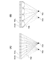
図2は、図1に示す表示部2における裸眼立体視を説明するための図である。そして、図2(A)は視差バリア方式を示す図であり、図2(B)はレンチキュラー方式を示す図である。
FIG. 2 is a diagram for explaining autostereoscopic viewing in the
図2(A)に示す視差バリア方式では、TFT液晶で構成された画素列の横方向に交互に左眼用画素領域701Lおよび右眼用画素領域701Rが設定される。そして、当該画素列の前面側に視差バリア702が設置され、この視差バリア702は縦方向のスリットで構成されている。この視差バリア702によって、左眼用画素領域701Lからの光が左眼703だけに到達し、右眼用画素領域701Rからの光が右眼704だけに到達する。
In the parallax barrier method shown in FIG. 2A, a left-
なお、視差バリア702を電子制御可能なスイッチ液晶によって構成するようにしてもよく、視差バリア702を、画素列の背後でかつ光源の手前側に配置するようにしてもよい。
Note that the
図2(B)に示すレンチキュラー方式では、画面の横方向に交互に左眼用画素領域705Lおよび右眼用画素領域705Rが設定される。そして、かまぼこ状のレンチキュラーレンズ706によって左眼用画素領域705Lからの光が左眼703だけに到達し、右眼用画素領域705Rからの光が右眼704だけに到達する。
In the lenticular method shown in FIG. 2B, a left-
このように視差分割方式においては、人間の左右の眼にそれぞれ異なる画像を映すことによって画像に奥行き感を出すことができる。 Thus, in the parallax division method, it is possible to give a sense of depth to an image by projecting different images to the left and right eyes of a human.
一方、DFD方式では、2枚のTFT液晶が所定の間隔をおいて前後に配置される。そして、2枚のTFT液晶に遠近に対応した明るさの割合で画像が表示される。ここでは、近くに位置する物体ほど、前側に配置されたTFT液晶に表示する画像の輝度を高くする。これによって前後のTFT液晶の間に連続的な奥行き感を出すことができる。 On the other hand, in the DFD method, two TFT liquid crystals are arranged at the front and back with a predetermined interval. An image is displayed on the two TFT liquid crystals at a brightness ratio corresponding to the distance. Here, the brightness of the image displayed on the TFT liquid crystal arranged on the front side is increased as the object is located closer. As a result, a continuous depth feeling can be produced between the front and rear TFT liquid crystals.
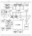
図3は、図1に示すデジタルカメラ1の構成を示すブロック図である。
FIG. 3 is a block diagram showing the configuration of the
図3を参照して、図示のデジタルカメラ1は撮影レンズ9を有しており、この撮影レンズ9にはフォーカスレンズが含まれている。撮影レンズの後段には絞り機能を備えるシャッター10が配置され、シャッター10を通過した光学像(被写体像)は撮像部11に結像される。撮像部11はCCD又はCMOSなどで構成され、光学像を電気信号(アナログ信号)に変換する。撮像部11の出力であるアナログ信号はA/D変換器12でデジタル信号(画像信号)に変換される。
With reference to FIG. 3, the illustrated
なお、撮影レンズ9、シャッター10、および撮像部11を含む撮像系はバリア8によって覆われ、これによって、撮像系の汚れおよび破損が防止される。
In addition, the imaging system including the photographing lens 9, the
画像処理部13はA/D変換器12の出力である画像信号又はメモリ制御部15から与えられる画像データに対して所定の画素補間および縮小などのリサイズ処理および色変換処理を行う。さらに、画像処理部13は画像データを用いて所定の演算処理を行って、この演算結果に基づいてシステム制御部21は露光制御および測距制御を行う。これによって、TTL(スルー・ザ・レンズ)方式のAF(オートフォーカス)処理、AE(自動露出)処理、およびEF(フラッシュプリ発光)処理が実行される。また、画像処理部13は画像データを用いて所定の演算処理を行って、この演算結果に基づいてTTL方式のAWB(オートホワイトバランス)処理を行う。
The
A/D変換器12の出力である画像信号は、画像処理部13およびメモリ制御部15を介して、又はメモリ制御部15を介してメモリ19に直接画像データとして書き込まれる。メモリ19は所定枚数の静止画像および所定時間の動画像、そして、音声データを格納するための十分な記憶容量を備えている。図示の例では、メモリ19は画像表示用メモリ(ビデオメモリ)を兼ねている。
The image signal that is the output of the A /
D/A変換器18は、メモリ19に格納された画像データをアナログ信号に変換して表示部2に与える。これによって、メモリ19に書き込まれた画像データは画像として表示部2に表示される。
The D /
不揮発性メモリ26は電気的に消去・記録可能なメモリであり、例えば、EEPROMが用いられる。この不揮発性メモリ26には、システム制御部21の動作用の定数およびプログラムなどが記憶されている。なお、このプログラムとは、例えば、後述するフローチャートを実行するためのプログラムをいう。
The
システム制御部21はデジタルカメラ1の全体を制御する。システム制御部21は不揮発性メモリ26に記録されたプログラムを実行して、後述する各処理を行う。システムメモリ27には、例えば、RAMが用いられる。システムメモリ27には、システム制御部21の動作用の定数、変数、および不揮発性メモリ26から読み出されたプログラムなどが展開される。また、システム制御部21はメモリ19、D/A変換器18、および表示部2などを制御して画面表示制御を実行する。
The
シャッターボタン3は、第1および第2のシャッタースイッチを備えており、シャッターボタン3の操作によってシステム制御部21に動作指示が入力される。第1シャッタースイッチは、シャッターボタン3の操作途中、所謂半押し(撮影準備指示)でオンとなって第1のシャッタースイッチ信号SW1を出力する。第1のシャッタースイッチ信号SW1によって、AF処理、AE処理、AWB処理、およびEF処理等が開始される。
The
第2シャッタースイッチは、シャッターボタン3の操作完了、所謂全押し(撮影指示)でオンとなって第2シャッタースイッチ信号SW2を出力する。システム制御部21は第2シャッタースイッチ信号SW2に応じて撮像部11の信号読み出しから記録媒体7に画像データを書き込むまでの一連の撮影処理を開始する。
The second shutter switch is turned on when the operation of the
電源制御部24は、例えば、電池検出回路、DC−DCコンバータ、およびスイッチ回路などを有している。そして、電源制御部24は電池の装着の有無、電池の種類、および電池残量の検出を行う。また、電源制御部24は検出結果およびシステム制御部21の指示に基づいてDC−DCコンバータを制御して、必要な電圧を必要な期間記録媒体7を含む各部に供給する。
The power
電源部25は、例えば、アルカリ電池又はリチウム電池等の一次電池、NiCd電池、NiMH電池、又はLi電池等の二次電池、そして、ACアダプターなどを有している。インターフェース20はメモリカード又はハードディスクなどの記録媒体7とデジタルカメラ1とのインターフェースである。記録媒体7は、例えば、メモリカードであって、半導体メモリ又は磁気ディスクなどから構成される。
The
図示のデジタルカメラ1はタッチパネル23を有しており、タッチパネル制御部22はタッチパネル23によって表示部2に対する接触を検知する。図示の例では、タッチパネル制御部22はタッチパネル23に対する操作を検出することができる。例えば、タッチパネル制御部22はタッチダウン、タッチオン、ムーブ、タッチアップ、およびタッチオフを検出する。
The illustrated
ここでは、タッチダウンとは、タッチパネル23を指又はペンで触れることをいう。タッチオンとは、タッチパネル23を指又はペンで触れている状態であることをいう。ムーブとは、タッチパネル23に指又はペンを触れた状態で移動していることをいう。タッチアップとは、タッチパネル23に触れていた指又はペンを離すことをいう。タッチオフとは、タッチパネル23に触れていない状態をいう。
Here, touchdown means touching the
タッチパネル制御部22は、上記の操作およびタッチパネル23上の指又はペンの位置を示す位置座標をシステム制御部21に通知する。そして、システム制御部21は通知情報に基づいてタッチパネル23上でどのような操作が行なわれたかについて判定する。システム制御部21は、ムーブの際にはタッチパネル23上で移動する指又はペンの移動方向を、位置座標の変化に応じてタッチパネル23上の垂直成分および水平成分毎に判定する。
The touch panel control unit 22 notifies the
ここでは、タッチパネル23にタッチダウンから所定のムーブを経てタッチアップをした際、これはストロークを描いたという。なお、素早くストロークを描く操作をフリックと呼ぶ。フリックは、タッチパネル23に指又はペンを触れた状態である程度の距離だけ指又はペンを素早く動かして離すという操作である。言い換えると、フリックとは、タッチパネル23を指ではじくように素早くなぞる操作である。つまり、システム制御部21は所定の距離以上を所定の速度以上でムーブしたことを検出した際にタッチアップを検出するとフリックが行なわれたと判定することになる。また、システム制御部21は所定の距離以上を所定の速度未満でムーブしたことを検出した際には、ドラッグが行なわれたと判定するものとする。
Here, when touch-up is performed on the
図1で関連して説明したように、操作入力用撮像部(L)5および操作入力用撮像部(R)6は操作者の指などの操作子を撮像するためのものである。操作入力用撮像部(L)5および操作入力用撮像部(R)6による撮像さの結果得られた操作子画像データは画像処理部13およびメモリ制御部15を介して、又はメモリ制御部15を介してメモリ19に直接書き込まれる。
As described with reference to FIG. 1, the operation input imaging unit (L) 5 and the operation input imaging unit (R) 6 are for imaging an operator such as an operator's finger. Manipulator image data obtained as a result of imaging by the operation input imaging unit (L) 5 and the operation input imaging unit (R) 6 is transmitted via the
距離・位置検出部16は、操作子画像データから操作子である操作者の指を検出する。そして、距離・位置検出部16は表示部2から指までの距離および表示部2の表示領域に対する指の位置を検出して、その検出結果をシステム制御部21に通知する。後述するように、システム制御部21は、表示部2から操作子までの距離および表示部2の表示領域に対する指の位置に応じて、表示部2に表示する表示形態を変えるよう表示制御を行う。
The distance /
非接触操作検出部17は、連続的に取得した複数の操作子画像データから操作子の位置について所定の間隔毎にその変化量を演算する。これによって、非接触操作検出部17は操作子の動きを検出して、操作子動き検出結果としてシステム制御部21に通知する。後述するように、システム制御部21は、操作者の指(操作子)が表示部2に触れていない状態において指の動きの軌跡に応じてデジタルカメラ1に対する操作指示を認識する。そして、システム制御部21は当該認識した操作指示に基づいてデジタルカメラ1を制御する。表示画像生成部14は、表示部2に表示するための表示データ(立体視画像データ)を生成する。
The non-contact
図4は、図3に示す表示画像生成部14の構成を詳細に示すブロック図である。
FIG. 4 is a block diagram showing in detail the configuration of the display
図示の例では、表示画像生成部14は視差分割方式を用いて、表示データに応じた表示画像を立体的表示で表示部2に表示する。表示画像生成部14は、背景画像生成部801、右眼用表示アイテム生成部802、左眼用表示アイテム生成部803、2次元表示アイテム生成部804、および立体視画像生成部805を備えている。
In the illustrated example, the display
背景画像生成部801は、メモリ制御部15を介してメモリ19から画像データを読込み背景画像表示データを生成する。そして、背景画像生成部801は背景画像表示データを立体視画像生成部805に出力する。
The background
右眼用表示アイテム生成部802は、メモリ制御部15を介してメモリ19から立体視対応表示アイテムにおける右眼用ビットマップデータを読み出して右眼用表示データを生成する。そして、右眼用表示アイテム生成部802は右眼用表示データを立体視画像生成部805に出力する。
The right-eye display
左眼用表示アイテム生成部803は、メモリ制御部15を介してメモリ19から立体視対応表示アイテムにおける左眼用ビットマップデータを読み出して左眼用表示データを生成する。そして、左眼用表示アイテム生成部803は左眼用表示データを立体視画像生成部805に出力する。
The left-eye display
ここで、立体視対応表示アイテム(操作アイテム)とは、当該立体視対応表示アイテムを裸眼立体視が可能な液晶ディスプレイで表示した際に、奥行き感を出すように構成された表示イメージである。例えば、立体視対応表示アイテムとは、操作用のスイッチおよびボタン、ダイヤルおよびアイコンを、表示部2の表示領域から所定の距離離れた空間上に仮想的に表現したものである。ここでは、デジタルカメラ1において、操作者の指を使って立体視対応表示アイテムを操作して操作指示を入力することができる。
Here, the stereoscopic vision display item (operation item) is a display image configured to give a sense of depth when the stereoscopic vision display item is displayed on a liquid crystal display capable of autostereoscopic viewing. For example, the stereoscopic display compatible display item is a virtual representation of operation switches, buttons, dials, and icons on a space that is a predetermined distance away from the display area of the
2次元表示アイテム生成部804は、メモリ制御部15を介してメモリ19から2次元表示アイテム用ビットマップデータを読み出して2次元表示アイテム用表示データを生成する。そして、2次元表示アイテム生成部804は2次元アイテム用表示データを立体視画像生成部805に出力する。
The two-dimensional display
ここで、2次元表示アイテムとは、2次元表示アイテムを裸眼立体視が可能な液晶ディスプレイで表示した際に奥行き感が出ないように構成された表示イメージである。なお、2次元表示アイテムとして、立体視対応表示アイテムと比べて奥行き感が識別できる程度に少なくなるように構成された表示イメージを用いるようにしてもよい。ここでは、操作者が指を表示部2に表示された2次元表示アイテムに対してタッチパネル23上でフリック操作するか又はタッチダウン操作すると、その操作指示を入力することができる。
Here, the two-dimensional display item is a display image configured to prevent a sense of depth when the two-dimensional display item is displayed on a liquid crystal display capable of autostereoscopic viewing. In addition, you may make it use the display image comprised so that a feeling of depth could be identified as a two-dimensional display item compared with a stereoscopic vision corresponding display item. Here, when the operator performs a flick operation on the two-dimensional display item displayed on the
立体視画像生成部805は、背景画像表示データ、右眼用表示データ、左眼用表示データ、および2次元表示アイテム用表示データに基づいて立体視画像データを生成する。そして、立体視画像生成部805はメモリ制御部15を介してメモリ19に立体視画像データを書き込む。
The stereoscopic
例えば、立体視画像生成部805は、まず背景画像表示データに右眼用表示データおよび2次元表示アイテム用表示データを重ね合わせて、右眼用立体視画像データを生成する。続いて、立体視画像生成部805は背景画像表示データに左眼用表示データおよび2次元表示アイテム用表示データを重ね合わせて、左眼用立体視画像データを生成する。
For example, the stereoscopic
立体視画像生成部805は右眼用立体視画像データおよび左眼用立体視画像データをそれぞれ画面の縦方向において複数の短冊領域に分割して右眼用短冊領域および左眼用短冊領域を得る。そして、立体視画像生成部805は右眼用短冊領域と左眼用短冊領域とを画面の横方向に交互に配列して、立体視画像データを生成する。この際、右眼用立体視画像データおよび左眼用立体視画像データは画像データに対して同一のものとして生成される。つまり、右眼用立体視画像データおよび左眼用立体視画像データの各々を表示した際には操作者には平面的な画像として見えることになる。
The stereoscopic
また、右眼用立体視画像データおよび左眼用立体視画像データは2次元表示アイテムに対して同一のものとして生成される。つまり、2次元表示アイテムを表示した際には操作者には平面的な表示アイテムとして見えることになる。一方、立体視対応表示アイテムに対して右目用立体視画像データおよび左目用立体視画像データは視差を有しているので、操作者には立体視対応表示アイテムが立体的な表示アイテムとして見えることになる。 Also, the right-eye stereoscopic image data and the left-eye stereoscopic image data are generated as the same for the two-dimensional display item. That is, when a two-dimensional display item is displayed, the operator sees it as a flat display item. On the other hand, since the stereoscopic image data for the right eye and the stereoscopic image data for the left eye have a parallax with respect to the stereoscopic display item, the stereoscopic display item can be viewed as a stereoscopic display item for the operator. become.
図示のデジタルカメラ1では、画像データ、2次元表示アイテム、および立体視対応表示アイテムを表示するか否かについて、それぞれ独立して制御することができる。
In the illustrated
図5は、図3に示すデジタルカメラ1における表示の切り替えおよびその操作を説明するためのフローチャートである。なお、図示のフローチャートに示す処理はシステム制御部21が不揮発性メモリ26に記録されているプログラムを実行することによって行われる。
FIG. 5 is a flowchart for explaining display switching and operation in the
図3および図5を参照して、いま、操作者が図1に示す電源スイッチ4を操作して電源をオンにすると、システム制御部21が記録媒体7に保存されている画像データを読み出して画像データに応じた画像を表示部2に表示する(ステップS302)。
3 and 5, when the operator operates the
図6は、図3に示す表示部2に表示される画像の一例を説明するための図である。そして、図6(A)は表示部2に表示された表示画像を示す図であり、図6(B)は操作候補アイテム904を表示画像902に重畳して表示した状態を示す図である。また、図6(C)は表示部2に操作可能表示が行われた状態を示す図である。
FIG. 6 is a diagram for explaining an example of an image displayed on the
上述のステップS302において、例えば、図6(A)に示す表示画像902が表示部2の表示領域に表示される。続いて、操作入力用撮像部(L)5および操作入力用撮像部(R)6による撮像の結果得られた操作子画像データに応じて、距離・位置検出部16は操作子であるユーザの指と表示部2との間の距離および指の位置を検出する。
In step S <b> 302 described above, for example, a
図7は、図3に示す距離・位置検出部16における距離および位置の検出を説明するための図である。
FIG. 7 is a diagram for explaining distance and position detection in the distance /
図7において、操作入力用撮像部(L)5および操作入力用撮像部(R)6の中心位置(仮想的な視点位置)をそれぞれPLおよびPRとする。中心位置PLおよびPRはx−z平面上にあり、さらに、操作入力用撮像部(L)5の撮像面(L)402および操作入力用撮像部(R)6の撮像面(R)403はx−y平面上にあるものとする。 In FIG. 7, the center positions (virtual viewpoint positions) of the operation input imaging unit (L) 5 and the operation input imaging unit (R) 6 are PL and PR, respectively. The center positions PL and PR are on the xz plane, and the imaging surface (L) 402 of the operation input imaging unit (L) 5 and the imaging surface (R) 403 of the operation input imaging unit (R) 6 are It shall be on the xy plane.
いま、操作子401の位置をPとして、位置Pおよび視点位置PLを結ぶ直線と撮像面(L)402との交点(3次元座標)をQLとし、位置Pおよび視点位置PRを結ぶ直線と撮像面(R)403との交点(3次元座標)をQRとする。そして、交点QLの撮像面(L)402における2次元座標をQL(xL,yL)とし、交点QRの撮像面(R)403における2次元座標をQR(xR,yR)とする。また、視点位置PLおよびPRの距離を2wとし、視点位置PLおよびPRから撮像面(L)402および撮像面(R)403までの距離をdとする。
Now, assuming that the position of the
x軸方向の単位ベクトルをi、y軸方向の単位ベクトルをj、そして、z軸方向の単位ベクトルをkとすると、式(1)〜式(4)が成立する。 When the unit vector in the x-axis direction is i, the unit vector in the y-axis direction is j, and the unit vector in the z-axis direction is k, Expressions (1) to (4) are established.
PL=−wi−dk (1)
PR=wi−dk (2)
QL=(xL−w)i+yLj (3)
QR=(xR+w)i+yRj (4)
視点位置PLおよび交点QLを結ぶ直線と視点位置PRおよび交点QRとを結ぶ直線は、位置Pで交差するので、式(5)が成立する。
PL = −wi−dk (1)
PR = wi-dk (2)
QL = (xL-w) i + yLj (3)
QR = (xR + w) i + yRj (4)
Since the straight line connecting the viewpoint position PL and the intersection point QL and the straight line connecting the viewpoint position PR and the intersection point QR intersect at the position P, Expression (5) is established.
P=PL+m(QL−PL)=PR+n(QR−PR) (5)
式(5)を未知数mおよびnに関して解くと式(6)が得られる。
P = PL + m (QL-PL) = PR + n (QR-PR) (5)
Solving equation (5) with respect to unknowns m and n yields equation (6).
m=n=2w/(xL−xR) (6)
これによって、操作子401の位置Pは式(7)によって求めることができる。
m = n = 2w / (xL-xR) (6)
As a result, the position P of the
P=(mxL−w)i+myLj+(m−1)dk (7)
システム制御部21は、距離・位置検出部16で検出した操作子401の位置Pを示す位置情報に応じて操作子401と表示部2との距離を示す操作子距離情報を得る。
P = (mxL−w) i + myLj + (m−1) dk (7)
The
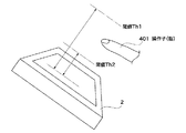
図8は図1に示す表示部2と操作子401との距離を示す斜視図である。
FIG. 8 is a perspective view showing the distance between the
図8に示すように、表示部2の表示領域と操作子401との距離(検出距離という)は閾値Th1およびTh2によって規定される。システム制御部21には予め距離情報として閾値Th1およびTh2が設定されており、閾値Th1は閾値Th2より大きい。そして、システム制御部21は検出距離が閾値TH1以下で閾値TH2を超える範囲にある状態を第1の近接状態とし、検出距離が閾値Th2以下の範囲にある状態を第2の近接状態とする。
As shown in FIG. 8, the distance (referred to as a detection distance) between the display area of the
まず、システム制御部21は、検出距離が閾値Th1以下であるか否かについて判定する。つまり、システム制御部21は操作子(指)401が表示領域(画面)に対して閾値Th1以下に接近したか否かについて判定する(ステップS303)。操作子401が画面に対して閾値Th1以下に接近しなければ(ステップS303において、NO)、システム制御部21は待機する。
First, the
操作子401が画面に対して閾値Th1以下に接近すると(ステップS303において、YES)、つまり、第1の接近状態であると、システム制御部21は表示部2の表示切り替えを行う。例えば、第1の近接状態においては、システム制御部21は図6(B)に示す表示画面を表示部2に表示する(ステップS304)。この表示画面には操作候補アイテム904が表示画像902に重畳して表示されている。そして、操作候補アイテム904は現在の操作モードにおいていずれの操作を行うことができるかを表しているが、この操作候補アイテム904によってユーザは操作入力を行うことはできない。
When the
続いて、システム制御部21は操作子(指)401が画面に対して閾値Th2以下に接近したか否かについて判定する(ステップS305)。操作子401が画面に対して閾値Th2以下に接近していないと(ステップS305において、NO)、システム制御部21は操作子401が画面に対して閾値Th1を超えて離れているか否かを判定する(ステップS306)。そして、操作子401が画面に対して閾値Th1を超えて離れていないと(ステップS306において、NO)、システム制御部21はステップS305の処理に戻って、再び操作子401が画面に対して閾値Th2以下に接近したか否かについて判定する。
Subsequently, the
一方、操作子401が画面に対して閾値Th1を超えて離れると(ステップS306において、YES)、システム制御部21は操作子401と画面とは近接状態にはないとして、操作候補アイテム904を表示画面から消去する(ステップS307)。つまり、システム制御部21は表示画面を図6(B)に示すアイテム表示状態から図6(A)に示す画像再生状態に切り替える。そして、システム制御部21はステップS303の処理に戻って、再び操作子401が画面に対して閾値Th1以下に接近したか否かについて判定する。
On the other hand, when the
操作子401が画面に対して閾値Th2以下に接近すると(ステップS305において、YES)、システム制御部21は第2の近接状態となったとして、操作候補アイテム904を操作可能表示に切り替える(ステップS308)。ここでは、例えば、システム制御部21は、図6(B)に示すアイテム表示状態から図6(C)に示す操作可能表示状態に表示画面を切り替える。
When the
この操作可能表示状態とは、操作可能アイテム905が表示画面に表示された状態をいい、例えば、システム制御部21は操作可能アイテム905を立体的に表示して操作可能表示状態とする。つまり、システム制御部21は操作可能アイテム905を強調して表示することになる。これによって、システム制御部21は操作可能アイテム905に対するユーザ入力を許可することになる。
The operable display state refers to a state in which the
この際、図6(C)に示すように、システム制御部21は操作可能アイテム905において可能な操作を矢印906および907で表示する。前述したように、非接触操作検出部17は、前述のようにして、操作可能アイテム905が操作されたか否か、そして、操作可能アイテム905においてどのような操作をされたかを検出する。システム制御部21は、非接触操作検出部17によって検出された操作子401の動きの軌跡(操作子動き検出結果)に応じて操作指示を認識する。これによって、システム制御部21は操作子401によって操作可能アイテム905が操作されたか否かを判定する(ステップS309)。
At this time, as shown in FIG. 6C, the
ここで、連続的に取得した複数の操作子画像データに応じて操作子401の動きを検出する手法について説明する。
Here, a method for detecting the movement of the
図9は、図3に示す非接触操作検出部による操作子401の動きの検出を説明するための図である。そして、図9(A)は所定の期間における操作子401の軌跡を示す図であり、図9(B)〜図9(E)は操作指示用軌跡データの一例を示す図である。
FIG. 9 is a diagram for explaining the detection of the movement of the
図9において、非接触操作検出部17は、距離・位置検出部16で検出された位置情報に基づいて所定の間隔毎に操作子401の変化量を示す変化ベクトルデータV(t)を取得する。非接触操作検出部17は所定の間隔毎の変化ベクトルV(t)、V(t+1)、V(t+2)・・・を組み合わせて操作子401の軌跡を導いて、操作子軌跡データを得る。そして、非接触操作検出部17はこの操作子軌跡データをシステム制御部21に与える。
In FIG. 9, the non-contact
一方、システムメモリ27には、予め複数の操作指示用軌跡データが記憶されている。この操作指示用軌跡データは、例えば、図9(B)〜図9(E)に示すベクトルデータ601〜604であり、操作指示用軌跡データ601および604の各々は反時計回りのベクトルデータである。また、操作指示用軌跡データ602および603の各々は時計回りのベクトルデータである。
On the other hand, the
システム制御部21は表示部2に操作可能アイテム905(図6(C))を表示する際、操作指示用軌跡データに応じて矢印906および907を表示することになる。
When the
システム制御部21は操作子軌跡データと操作指示用軌跡データ601、602、603、又は604とを比較する。いま、表示部2に操作指示用軌跡データ601に応じた矢印(操作指示)が表示されている場合には、システム制御部21は操作子軌跡データと操作指示用軌跡データ601とを比較する。操作子軌跡データと操作指示用軌跡データとが一致していると、システム制御部21は操作可能アイテム905に対して操作が行われた判定する。
The
操作可能アイテム905に対して操作が行われると(ステップS309において、YES)、システム制御部21は操作可能アイテム905に対応した所定の処理を行う(ステップS310)。図6(C)に示す例では、ユーザが矢印906又は907の方向に操作可能アイテム905を操作すると、システム制御部21は設定された日付に対応する画像送りを行う。
When operation is performed on operable item 905 (YES in step S309),
所定の処理(ここでは、画像送り処理)を行った後、システム制御部21はステップS309の処理に戻って、再度操作可能アイテム905が操作されたか否かを判定する。
After performing a predetermined process (here, image feed process), the
操作可能アイテム905に対して操作が行われないと(ステップS309において、NO)、システム制御部21は操作子401が画面から閾値Th2を超えて離れているか否かを判定する(ステップS311)。操作子401が画面から閾値Th2を超えて離れてないと判定すると(ステップS311において、NO)、システム制御部21はユーザが再度操作可能アイテム905を操作したい状態であると認識して、ステップS309の処理に戻る。
If no operation is performed on the operable item 905 (NO in step S309), the
操作子401が画面から閾値Th2を超えて離れていると判定すると(ステップS311において、YES)、システム制御部21は操作子401が画面から閾値Th1を越えて離れているか否かを判定する(ステップS312)。操作子401が画面から閾値Th1を超えて離れていないと判定すると(ステップS312において、NO)、システム制御部21はステップS304の処理に戻って、操作可能アイテム905の表示を解除して、操作候補アイテム904を画面表示する。
If it is determined that the
一方、操作子401が画面から閾値Th1を超えて離れていると判定すると(ステップS312において、YES)、システム制御部21はステップS302の処理に戻って、操作候補アイテム904の表示を解除して、表示画像(図6(A))のみを画面表示する。
On the other hand, if it is determined that the
このように、第1の実施形態では、操作子401と画面との距離に応じて画面上に表示されるアイテムを表示するか否かを決定するようにしたので、ユーザによる画像確認を妨げることない。そして、操作子401が画面に接近した場合に、つまり、ユーザが操作入力を望む場合に、操作可能アイテムを画面上に表示するようにしたので、ユーザは画像確認を行った後操作入力を行うことができる。
As described above, in the first embodiment, since it is determined whether or not to display an item displayed on the screen according to the distance between the
さらに、第1の実施形態では、操作子401と画面との距離に応じて段階的に画面表示を切り替えるようにしたので、ユーザはデジタルカメラに備えられた操作部を操作することなく、直感的に操作の切り替えおよび操作入力を行うことができる。
Furthermore, in the first embodiment, the screen display is switched stepwise in accordance with the distance between the
なお、第1の実施形態においては、操作子401と表示部2(画面)との距離に応じて近接状態であるか否かを判定するようにしたが、操作子401の大きさの変化を検出することによって近接状態であるか否かを判別するようにしてもよい。
In the first embodiment, it is determined whether or not the proximity of the
また、システム制御部21は第1の近接状態であると判定した際に、操作子401と閾値Th2までの距離を判定して操作候補アイテム904の表示を変化させるようにしてもよい。例えば、操作子401が閾値Th1から閾値Th2に近づくにつれて、システム制御部21は操作候補アイテム904を徐々に拡大表示させるようにする。さらに、システム制御部21は操作候補アイテム904を徐々に立体的な表示にするようにしてもよく、操作候補アイテム904の色を薄い色から濃い色に変化させるようにしてもよい。
Further, when the
このように、操作候補アイテム904の表示形態を変化させれば、ユーザは操作子401がいずれの操作候補アイテムに近接しているのかについて容易に視覚的に確認することができる。
Thus, if the display form of the
図6(C)においては、操作可能アイテム905は立体的に表示しているが、操作候補アイテム904の表示と区別できる表示であれば、操作可能アイテム905と操作候補アイテム904とにおいて色を変化させるようにしてもよい。又は大きさを変化させるようにしてもよい。これによって、操作可能アイテム905を立体的に表示できない場合であって、ユーザは容易に視覚的に操作可能状態を確認することができる。
In FIG. 6C, the
また、図6(C)に関連する説明では、システム制御部21は操作可能アイテム905の操作についてタッチパネルの接触に拠らず、非接触(所謂ジェスチャ入力)によって判定している。一方、操作可能アイテム905が立体的な表示ではない場合などにおいては、タッチパネル23に対するタッチダウン、タッチオン、およびムーブなどによって操作入力を判定するようにしてもよい。この際、システム制御部21は誤動作を防ぐために操作可能アイテム905以外の表示アイテムに対する操作指示入力を無効にするようにしてよい。
In the description related to FIG. 6C, the
[第2の実施形態]
続いて、本発明の第2の実施形態によるデジタルカメラの一例について説明する。なお、第2の実施形態におけるデジタルカメラの構成は図1〜図3で説明したデジタルカメラの構成と同様である。
[Second Embodiment]
Next, an example of a digital camera according to the second embodiment of the present invention will be described. The configuration of the digital camera in the second embodiment is the same as the configuration of the digital camera described with reference to FIGS.
第2の実施形態によるデジタルカメラ1では、操作子の形状に応じて操作入力の切り替えが行われる。つまり、ここでは、操作子が表示部に近づいた際の操作子の形状によって操作入力(操作内容)内容が切り替えられる。
In the
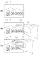
図10は、本発明の第2の実施形態によるデジタルカメラにおいて表示部2に画像を表示する再生モードの一例を説明するための図である。そして、図10(A)は表示部2に画像が表示された状態を示す図であり、図10(B)は操作子401が画面に接近しつつある状態を示す図である。図10(C)は操作子401が画面に接近した状態を示す図である。
FIG. 10 is a diagram for explaining an example of a playback mode in which an image is displayed on the
図10において、再生モードでは、システム制御部21の制御下で記録媒体7に保存された画像データが画像として操作者の指示に応じて表示部2に表示される。図10(A)に示す表示状態では、ユーザは再生モードにおいて表示画像1001を表示部2に画面表示して、当該表示画像1001を確認しているものとする。そして、確認の結果、ユーザは操作入力を行うため、操作子401を画面に近づけるものとする。
In FIG. 10, in the reproduction mode, the image data stored in the
操作入力のためユーザが指(操作子)401を画面に近づけ、第1の実施形態で説明したように、操作子401と画面との関係が第1の接近状態となると、システム制御部21は画面表示の切り替えを行う。図10(B)は第1の接近状態となった際の画面表示であり、ここでは、操作候補アイテム1003および1004が表示画像1001に重畳して画面表示される。
When the user brings the finger (operator) 401 close to the screen for operation input, and the relationship between the
図示の例では、操作候補アイテム1003および1004を重畳する際、操作候補アイテム1003および1004の輪郭のみ点線で表示される(視認を妨げない表示形態で表示される)。このため、ユーザは表示画像1001の視認を妨げられることがない。なお、図10(B)においては、操作候補アイテム1003は画像拡大ボタンを表し、操作候補アイテム1004は画像削除ボタンを表している。
In the illustrated example, when the
ところで、図5に示すフローチャートを用いて説明したように、ステップS303において、操作子401が表示部2(画面)に閾値Th1以下に近接すると、システム制御部21はステップS304において操作候補アイテム1003および1004を表示する。この際、システム制御部21は操作子画像データに基づいて操作子401の形状を判定する(つまり、操作子401の形状を識別して識別結果を得る)。さらに、システム制御部21は操作子104の形状(識別結果)に応じてユーザがどのような操作をしようとしているのかを推定する。そして、この推定結果に応じて、システム制御部21は操作候補アイテム1003および1004の表示を切り替える。
By the way, as described with reference to the flowchart shown in FIG. 5, when the
図10(B)に示す例では、操作子401、つまり、人差し指で操作しようとしており、人差し指が立てられた状態にある。このように人差し指が立てられた状態で画面に近接すると、システム制御部21は、ユーザが操作候補アイテムを選択しタッチによって操作入力を行うと推定する。そこで、システム制御部21は表示部2に、選択ボタン形状の操作候補アイテム1003および1004を表示画像1001に重畳して表示する。
In the example shown in FIG. 10B, the
図5に示すステップS305で説明したように、操作子401が操作候補アイテム1004に対して閾値Th2以下に近接すると、システム制御部21は操作候補アイテム1004を操作可能アイテム1005に切り替えて画面表示する(図10(C)参照)。この際、誤操作を防止するため、システム制御部21は操作可能アイテム1005以外の操作候補アイテム1003に対する操作指示入力を無効にするように制御する。
As described in step S305 illustrated in FIG. 5, when the
また、操作子401が複数の操作候補アイテムに近接している場合には、システム制御部21は操作子401が最も近接している操作候補アイテムを操作可能アイテムに切り替えて、当該操作可能アイテム以外の操作候補アイテムを消去する。なお、操作可能アイテム以外の操作候補アイテムを画面隅に縮小表示するなどして表示形態を変更するようにしてもよい。
Further, when the
このように、使用しない操作候補アイテムを目立たなくすれば、ユーザが操作入力を行う際に混乱を来たすことを防止することができる。さらに、ユーザの画像閲覧の邪魔となることも防止することができる。 In this way, if the operation candidate items that are not used are not conspicuous, it is possible to prevent the user from being confused when performing the operation input. Furthermore, it is possible to prevent the user from viewing the image.
図5に示すステップS309で説明したようにして、システム制御部21は操作子401が操作可能アイテム1005をタッチダウンしたと判定すると、表示画像1001を削除する。
As described in step S <b> 309 shown in FIG. 5, when the
図11は、本発明の第2の実施形態によるデジタルカメラにおいて表示部に画像を表示する再生モードの他の例を説明するための図である。そして、図11(A)は表示部に画像が表示された状態を示す図であり、図11(B)は操作子が画面に接近しつつある状態を示す図である。また、図11(C)は操作子が画面に接近した状態を示す図である。 FIG. 11 is a diagram for explaining another example of the reproduction mode in which an image is displayed on the display unit in the digital camera according to the second embodiment of the present invention. FIG. 11A is a diagram showing a state in which an image is displayed on the display unit, and FIG. 11B is a diagram showing a state in which the operator is approaching the screen. FIG. 11C is a diagram showing a state in which the operation element approaches the screen.
図11(A)に示す表示状態では、ユーザは再生モードにおいて表示画像1101を表示部2に画面表示して、当該表示画像1101を確認しているものとする。前述したように、操作子401が表示部2(画面)に閾値Th1以下(第1の閾値距離以下)に近接すると、システム制御部21は操作候補アイテム1103および1004を表示する。この際、システム制御部21は操作子画像データに基づいて操作子401の形状を判定する。
In the display state shown in FIG. 11A, it is assumed that the user displays the
図11(B)に示す例では、ユーザは操作子401である親指と人差し指とを有して物をつまむようにしている。つまり、操作子401は物をつまむような形状をしている。このように操作子401である指が物をつまむような形状で画面に近接すると、システム制御部21は、ユーザがダイヤル式の表示アイテムを回転する操作を行うと推定する。その結果、システム制御部21は画面に、ダイヤル形状の操作候補アイテム1103を表示画像1101に重畳して表示する。この際には、システム制御部21は操作候補アイテム1103の輪郭を点線で表示して、ユーザが画像を確認する際の妨げにならないようにする。
In the example shown in FIG. 11B, the user has a thumb and an index finger, which are the
操作子401が操作候補アイテム1103に閾値Th2以下(第2の閾値距離以下)に近接すると、システム制御部21は操作候補アイテム1103を操作可能アイテム1104に切り替える(図11(C)参照)。ここでは、システム制御部21は操作可能アイテム1104に操作子401で可能な操作を矢印1105および1106で表示する。
When the
そして、図5に示すステップS309およびS310で説明したように、システム制御部21は、非接触操作検出部17で検出された操作子401の軌跡に応じて操作子401が動いた方向を判定して操作入力に応じた日付に画像送りを実行する。
Then, as described in steps S309 and S310 illustrated in FIG. 5, the
なお、図11で説明したように、ユーザがタッチパネル操作を行わない場合には、システム制御部21は誤操作防止のためタッチパネルに対する操作入力を無効とするようにしてもよい。
As described with reference to FIG. 11, when the user does not perform the touch panel operation, the
このように、第2の実施形態では、ユーザは画像の確認を妨げられることなく、表示アイテムを用いて操作入力を行うことができる。さらに、ここでは、操作子の形状に応じた操作候補アイテムを表示するようにしたので、ユーザは操作子の形状を変化させれば、当該形状に応じた操作入力を簡単に実現することができる。従って、ユーザは極めて直感的にデジタルカメラの操作を行うことができる。 As described above, in the second embodiment, the user can perform an operation input using the display item without being prevented from confirming the image. Furthermore, since the operation candidate item corresponding to the shape of the operation element is displayed here, if the user changes the shape of the operation element, an operation input corresponding to the shape can be easily realized. . Therefore, the user can operate the digital camera very intuitively.
上述の説明から明らかなように、図3において、距離・位置検出部16(検出センサ)およびシステム制御部21が距離検出手段として機能する。また、システム制御部21は第1の表示制御手段および第2の表示制御手段として機能する。さらに、操作入力用撮像部5および6とシステム制御部21は識別手段として機能する。なお、撮像部11、A/D変換器12、画像処理部13、およびシステム制御部21などが画像処理装置を構成することになる。
As is apparent from the above description, in FIG. 3, the distance / position detection unit 16 (detection sensor) and the
以上、本発明について実施の形態に基づいて説明したが、本発明は、これらの実施の形態に限定されるものではなく、この発明の要旨を逸脱しない範囲の様々な形態も本発明に含まれる。 As mentioned above, although this invention was demonstrated based on embodiment, this invention is not limited to these embodiment, Various forms of the range which does not deviate from the summary of this invention are also contained in this invention. .
例えば、上記の実施の形態の機能を制御方法として、この制御方法を画像処理装置に実行させるようにすればよい。また、上述の実施の形態の機能を有するプログラムを制御プログラムとして、この制御プログラムを画像処理装置が備えるコンピュータに実行させるようにしてもよい。なお、制御プログラムは、例えば、コンピュータに読み取り可能な記録媒体に記録される。 For example, the function of the above embodiment may be used as a control method, and this control method may be executed by the image processing apparatus. In addition, a program having the functions of the above-described embodiments may be used as a control program, and the control program may be executed by a computer included in the image processing apparatus. The control program is recorded on a computer-readable recording medium, for example.
この際、制御方法および制御プログラムは、少なくとも距離検出ステップ、第1の表示制御ステップ、および第2の表示制御ステップを有することになる。 At this time, the control method and the control program have at least a distance detection step, a first display control step, and a second display control step.
また、本発明は、以下の処理を実行することによっても実現される。即ち、上述した実施形態の機能を実現するソフトウェア(プログラム)を、ネットワーク又は各種記録媒体を介してシステム或いは装置に供給し、そのシステム或いは装置のコンピュータ(またはCPUやMPU等)がプログラムを読み出して実行する処理である。 The present invention can also be realized by executing the following processing. That is, software (program) for realizing the functions of the above-described embodiments is supplied to a system or apparatus via a network or various recording media, and a computer (or CPU, MPU, etc.) of the system or apparatus reads the program. It is a process to be executed.
1 デジタルカメラ
2 表示部
7 記録媒体
11 撮像部
13 画像処理部
15 メモリ制御部
16 距離・位置検出部
17 非接触操作検出部
21 システム制御部
23 タッチパネル
DESCRIPTION OF
Claims (10)
前記画面と前記操作子との距離を検出して検出距離を得る距離検出手段と、
前記検出距離が所定の第1の閾値距離以下となると、少なくとも1つの操作候補アイテムを前記画面に表示する第1の表示制御手段と、
前記検出距離が前記第1の閾値距離以下となった際、前記検出距離に応じて前記操作候補アイテムの表示形態を変化させて前記操作候補アイテムを操作可能アイテムとして表示する第2の表示制御手段とを有することを特徴とする画像処理装置。 When an image corresponding to the image data is displayed on the screen, an operation item is displayed on the screen to input an operation for performing the process related to the image, and the operation item is operated by an operator, An image processing apparatus that performs processing corresponding to an operation item,
Distance detecting means for detecting a distance between the screen and the operation element to obtain a detection distance;
First display control means for displaying at least one operation candidate item on the screen when the detection distance is equal to or less than a predetermined first threshold distance;
Second display control means for displaying the operation candidate item as an operable item by changing a display form of the operation candidate item according to the detection distance when the detection distance is equal to or less than the first threshold distance. An image processing apparatus comprising:
前記第1の表示制御手段は前記識別結果に対応する操作候補アイテムを前記画面に表示することを特徴とする請求項1〜6のいずれか1項に記載の画像処理装置。 An identification means for identifying the shape of the operation element and obtaining an identification result;
The image processing apparatus according to claim 1, wherein the first display control unit displays an operation candidate item corresponding to the identification result on the screen.
検出センサによって前記画面と前記操作子との距離を検出して検出距離を得る距離検出ステップと、
前記検出距離が所定の第1の閾値距離以下となると、少なくとも1つの操作候補アイテムを前記画面に表示する第1の表示制御ステップと、
前記検出距離が前記第1の閾値距離以下となった際、前記検出距離に応じて前記操作候補アイテムの表示形態を変化させて前記操作候補アイテムを操作可能アイテムとして表示する第2の表示制御ステップとを有することを特徴とする制御方法。 When an image corresponding to the image data is displayed on the screen, an operation item is displayed on the screen to input an operation for performing the process related to the image, and the operation item is operated by an operator, A control method of an image processing apparatus that performs processing corresponding to an operation item,
A distance detection step of detecting a distance between the screen and the operation element by a detection sensor to obtain a detection distance;
A first display control step of displaying at least one operation candidate item on the screen when the detection distance is equal to or less than a predetermined first threshold distance;
A second display control step of displaying the operation candidate item as an operable item by changing a display form of the operation candidate item according to the detection distance when the detection distance is equal to or less than the first threshold distance; The control method characterized by having.
前記画像処理装置が備えるコンピュータに、
検出センサによって前記画面と前記操作子との距離を検出して検出距離を得る距離検出ステップと、
前記検出距離が所定の第1の閾値距離以下となると、少なくとも1つの操作候補アイテムを前記画面に表示する第1の表示制御ステップと、
前記検出距離が前記第1の閾値距離以下となった際、前記検出距離に応じて前記操作候補アイテムの表示形態を変化させて前記操作候補アイテムを操作可能アイテムとして表示する第2の表示制御ステップとを実行させることを特徴とする制御プログラム。 When an image corresponding to the image data is displayed on the screen, an operation item is displayed on the screen to input an operation for performing the process related to the image, and the operation item is operated by an operator, A control program used in an image processing apparatus that performs processing corresponding to an operation item,
In the computer provided in the image processing apparatus,
A distance detection step of detecting a distance between the screen and the operation element by a detection sensor to obtain a detection distance;
A first display control step of displaying at least one operation candidate item on the screen when the detection distance is equal to or less than a predetermined first threshold distance;
A second display control step of displaying the operation candidate item as an operable item by changing a display form of the operation candidate item according to the detection distance when the detection distance is equal to or less than the first threshold distance; A control program characterized by causing
被写体を撮影して前記画像データを得る撮像手段とを有することを特徴とする撮像装置。 The image processing apparatus according to any one of claims 1 to 7,
An image pickup apparatus comprising: an image pickup unit that picks up a subject and obtains the image data.
Priority Applications (3)
| Application Number | Priority Date | Filing Date | Title |
|---|---|---|---|
| JP2011120341A JP2012248066A (en) | 2011-05-30 | 2011-05-30 | Image processing device, control method of the same, control program and imaging apparatus |
| US13/453,437 US8947352B2 (en) | 2011-05-30 | 2012-04-23 | Image processing apparatus capable of displaying operation item, method of controlling the same, image pickup apparatus, and storage medium |
| US14/589,040 US20150116775A1 (en) | 2011-05-30 | 2015-01-05 | Image processing apparatus capable of displaying operation item, method of controlling the same, image pickup apparatus, and storage medium |
Applications Claiming Priority (1)
| Application Number | Priority Date | Filing Date | Title |
|---|---|---|---|
| JP2011120341A JP2012248066A (en) | 2011-05-30 | 2011-05-30 | Image processing device, control method of the same, control program and imaging apparatus |
Publications (1)
| Publication Number | Publication Date |
|---|---|
| JP2012248066A true JP2012248066A (en) | 2012-12-13 |
Family
ID=47261263
Family Applications (1)
| Application Number | Title | Priority Date | Filing Date |
|---|---|---|---|
| JP2011120341A Withdrawn JP2012248066A (en) | 2011-05-30 | 2011-05-30 | Image processing device, control method of the same, control program and imaging apparatus |
Country Status (2)
| Country | Link |
|---|---|
| US (2) | US8947352B2 (en) |
| JP (1) | JP2012248066A (en) |
Cited By (5)
| Publication number | Priority date | Publication date | Assignee | Title |
|---|---|---|---|---|
| JP2014206782A (en) * | 2013-04-10 | 2014-10-30 | Necカシオモバイルコミュニケーションズ株式会社 | Operation processing apparatus, operation processing method, and program |
| WO2016117325A1 (en) * | 2015-01-20 | 2016-07-28 | パナソニックIpマネジメント株式会社 | Display device |
| WO2016117326A1 (en) * | 2015-01-20 | 2016-07-28 | パナソニックIpマネジメント株式会社 | Display device |
| JP2016534483A (en) * | 2013-09-24 | 2016-11-04 | マイクロソフト テクノロジー ライセンシング,エルエルシー | Presentation of control interface on devices with touch function based on presence or absence of motion |
| US10444961B2 (en) | 2014-08-12 | 2019-10-15 | Microsoft Technology Licensing, Llc | Hover-based interaction with rendered content |
Families Citing this family (14)
| Publication number | Priority date | Publication date | Assignee | Title |
|---|---|---|---|---|
| KR20140089766A (en) * | 2013-01-07 | 2014-07-16 | 삼성전자주식회사 | Portable device control method using a electric pen and portable device thereof |
| SE536989C2 (en) * | 2013-01-22 | 2014-11-25 | Crunchfish Ab | Improved feedback in a seamless user interface |
| SG2014010144A (en) * | 2013-02-20 | 2014-08-28 | Panasonic Corp | Control method for information apparatus and program |
| US20160378967A1 (en) * | 2014-06-25 | 2016-12-29 | Chian Chiu Li | System and Method for Accessing Application Program |
| JP6361332B2 (en) * | 2014-07-04 | 2018-07-25 | 富士通株式会社 | Gesture recognition apparatus and gesture recognition program |
| US9454235B2 (en) * | 2014-12-26 | 2016-09-27 | Seungman KIM | Electronic apparatus having a sensing unit to input a user command and a method thereof |
| US10216405B2 (en) * | 2015-10-24 | 2019-02-26 | Microsoft Technology Licensing, Llc | Presenting control interface based on multi-input command |
| CN107959846B (en) * | 2017-12-06 | 2019-12-03 | 苏州佳世达电通有限公司 | Display device and image display method |
| CN110389799B (en) * | 2018-04-20 | 2022-06-07 | 中兴通讯股份有限公司 | Element display method and device, terminal, storage medium and electronic device |
| JP2020052681A (en) | 2018-09-26 | 2020-04-02 | シュナイダーエレクトリックホールディングス株式会社 | Operation processing device |
| CN110187812B (en) * | 2019-04-28 | 2022-04-08 | 珠海格力电器股份有限公司 | Method for activating touch screen, electronic equipment and touch communication equipment |
| CN110475000B (en) * | 2019-08-08 | 2021-07-13 | Oppo(重庆)智能科技有限公司 | Touch screen point reporting method and related equipment |
| CN110956939B (en) * | 2019-11-27 | 2022-12-13 | 华为技术有限公司 | Method for adjusting screen brightness and electronic equipment |
| KR20210100850A (en) * | 2020-02-07 | 2021-08-18 | 삼성전자주식회사 | Electronic device and system for processing user input and method thereof |
Family Cites Families (13)
| Publication number | Priority date | Publication date | Assignee | Title |
|---|---|---|---|---|
| JPH10105735A (en) | 1996-09-30 | 1998-04-24 | Terumo Corp | Input device and picture display system |
| JP2003005912A (en) * | 2001-06-20 | 2003-01-10 | Hitachi Ltd | Display device with touch panel and display method |
| EP1769326A2 (en) * | 2004-06-29 | 2007-04-04 | Koninklijke Philips Electronics N.V. | A method and device for preventing staining of a display device |
| JP4479962B2 (en) | 2005-02-25 | 2010-06-09 | ソニー エリクソン モバイル コミュニケーションズ, エービー | Input processing program, portable terminal device, and input processing method |
| US8284165B2 (en) * | 2006-10-13 | 2012-10-09 | Sony Corporation | Information display apparatus with proximity detection performance and information display method using the same |
| JP2010521732A (en) * | 2007-03-14 | 2010-06-24 | パワー2ビー,インコーポレイティド | Display device and information input device |
| US8432365B2 (en) * | 2007-08-30 | 2013-04-30 | Lg Electronics Inc. | Apparatus and method for providing feedback for three-dimensional touchscreen |
| WO2009067224A1 (en) * | 2007-11-19 | 2009-05-28 | Cirque Corporation | Touchpad combined with a display and having proximity and touch sensing capabilities |
| KR101506488B1 (en) * | 2008-04-04 | 2015-03-27 | 엘지전자 주식회사 | Mobile terminal using proximity sensor and control method thereof |
| JP5374071B2 (en) * | 2008-05-23 | 2013-12-25 | 株式会社Pfu | Mobile terminal and region specifying process execution method |
| US9477396B2 (en) * | 2008-11-25 | 2016-10-25 | Samsung Electronics Co., Ltd. | Device and method for providing a user interface |
| JP5781080B2 (en) * | 2010-10-20 | 2015-09-16 | 三菱電機株式会社 | 3D stereoscopic display device and 3D stereoscopic display processing device |
| JP5648844B2 (en) * | 2010-12-21 | 2015-01-07 | ソニー株式会社 | Image display control apparatus and image display control method |
-
2011
- 2011-05-30 JP JP2011120341A patent/JP2012248066A/en not_active Withdrawn
-
2012
- 2012-04-23 US US13/453,437 patent/US8947352B2/en active Active
-
2015
- 2015-01-05 US US14/589,040 patent/US20150116775A1/en not_active Abandoned
Cited By (6)
| Publication number | Priority date | Publication date | Assignee | Title |
|---|---|---|---|---|
| JP2014206782A (en) * | 2013-04-10 | 2014-10-30 | Necカシオモバイルコミュニケーションズ株式会社 | Operation processing apparatus, operation processing method, and program |
| JP2016534483A (en) * | 2013-09-24 | 2016-11-04 | マイクロソフト テクノロジー ライセンシング,エルエルシー | Presentation of control interface on devices with touch function based on presence or absence of motion |
| US10775997B2 (en) | 2013-09-24 | 2020-09-15 | Microsoft Technology Licensing, Llc | Presentation of a control interface on a touch-enabled device based on a motion or absence thereof |
| US10444961B2 (en) | 2014-08-12 | 2019-10-15 | Microsoft Technology Licensing, Llc | Hover-based interaction with rendered content |
| WO2016117325A1 (en) * | 2015-01-20 | 2016-07-28 | パナソニックIpマネジメント株式会社 | Display device |
| WO2016117326A1 (en) * | 2015-01-20 | 2016-07-28 | パナソニックIpマネジメント株式会社 | Display device |
Also Published As
| Publication number | Publication date |
|---|---|
| US20120306738A1 (en) | 2012-12-06 |
| US20150116775A1 (en) | 2015-04-30 |
| US8947352B2 (en) | 2015-02-03 |
Similar Documents
| Publication | Publication Date | Title |
|---|---|---|
| JP2012248066A (en) | Image processing device, control method of the same, control program and imaging apparatus | |
| US20110083106A1 (en) | Image input system | |
| EP3054376B1 (en) | Electronic apparatus and control method of the same | |
| JP7005161B2 (en) | Electronic devices and their control methods | |
| CN109218608B (en) | Electronic device, control method thereof, and storage medium | |
| US10222950B2 (en) | Image processing apparatus and method | |
| CN108243307B (en) | Image pickup control device and control method thereof | |
| US10324597B2 (en) | Electronic apparatus and method for controlling the same | |
| JP2018013745A (en) | Electronic equipment and control method therefor | |
| EP2533133A1 (en) | Information processing apparatus, information processing method, and program | |
| JP7433810B2 (en) | Electronic devices, control methods for electronic devices, programs and storage media | |
| JP2019075699A (en) | Electronic device and control method of the same | |
| US10623610B2 (en) | Display processing device and display processing method | |
| US11949977B2 (en) | Electronic equipment, method for controlling the same, and recording medium | |
| JP2013017088A (en) | Imaging apparatus, control method of the same, control program, and recording medium | |
| JP5976174B2 (en) | Image processing apparatus, control method therefor, and program | |
| US10924680B2 (en) | Image capture control apparatus and method of controlling the same | |
| JP2018132827A (en) | Display control apparatus, control method thereof, program, and recording medium | |
| JP2012194760A (en) | Image processing apparatus and method of controlling the same, and program | |
| CN111782053A (en) | Model editing method, device, equipment and storage medium | |
| EP4307660A1 (en) | Information processing apparatus, information processing method, and program | |
| JP6525753B2 (en) | Display control device, control method thereof, and program | |
| CN112887585B (en) | Display control apparatus, control method thereof, and storage medium | |
| US20220385877A1 (en) | Electronic equipment, control method therefor, and storage medium | |
| JP6873792B2 (en) | Imaging control device and its control method |
Legal Events
| Date | Code | Title | Description |
|---|---|---|---|
| A300 | Application deemed to be withdrawn because no request for examination was validly filed |
Free format text: JAPANESE INTERMEDIATE CODE: A300 Effective date: 20140805 |