EP2961075B1 - Pilot transmission and channel estimation for a communication system utilizing frequency division multiplexing - Google Patents
Pilot transmission and channel estimation for a communication system utilizing frequency division multiplexing Download PDFInfo
- Publication number
- EP2961075B1 EP2961075B1 EP15170466.5A EP15170466A EP2961075B1 EP 2961075 B1 EP2961075 B1 EP 2961075B1 EP 15170466 A EP15170466 A EP 15170466A EP 2961075 B1 EP2961075 B1 EP 2961075B1
- Authority
- EP
- European Patent Office
- Prior art keywords
- pilot
- symbols
- symbol
- data
- sequence
- Prior art date
- Legal status (The legal status is an assumption and is not a legal conclusion. Google has not performed a legal analysis and makes no representation as to the accuracy of the status listed.)
- Active
Links
- 230000005540 biological transmission Effects 0.000 title description 42
- 238000004891 communication Methods 0.000 title description 26
- 125000004122 cyclic group Chemical group 0.000 claims description 20
- 230000004044 response Effects 0.000 description 54
- 238000000034 method Methods 0.000 description 52
- 238000012545 processing Methods 0.000 description 10
- 230000000717 retained effect Effects 0.000 description 10
- 238000010586 diagram Methods 0.000 description 8
- 238000001228 spectrum Methods 0.000 description 8
- 238000001914 filtration Methods 0.000 description 7
- 230000003595 spectral effect Effects 0.000 description 7
- 238000012805 post-processing Methods 0.000 description 6
- 230000006870 function Effects 0.000 description 5
- 239000011159 matrix material Substances 0.000 description 5
- 101000802640 Homo sapiens Lactosylceramide 4-alpha-galactosyltransferase Proteins 0.000 description 4
- 102100035838 Lactosylceramide 4-alpha-galactosyltransferase Human genes 0.000 description 4
- 230000002441 reversible effect Effects 0.000 description 4
- 230000002123 temporal effect Effects 0.000 description 4
- 238000012549 training Methods 0.000 description 4
- 238000001514 detection method Methods 0.000 description 3
- 239000000654 additive Substances 0.000 description 2
- 230000000996 additive effect Effects 0.000 description 2
- 230000001419 dependent effect Effects 0.000 description 2
- 238000013461 design Methods 0.000 description 2
- 230000000694 effects Effects 0.000 description 2
- 238000005562 fading Methods 0.000 description 2
- 238000009825 accumulation Methods 0.000 description 1
- 230000002411 adverse Effects 0.000 description 1
- 238000003491 array Methods 0.000 description 1
- 239000000969 carrier Substances 0.000 description 1
- 230000001427 coherent effect Effects 0.000 description 1
- 230000000295 complement effect Effects 0.000 description 1
- 230000002939 deleterious effect Effects 0.000 description 1
- 230000007774 longterm Effects 0.000 description 1
- 238000013507 mapping Methods 0.000 description 1
- 238000005192 partition Methods 0.000 description 1
- 230000000737 periodic effect Effects 0.000 description 1
- 230000003068 static effect Effects 0.000 description 1
Images


Classifications
-
- H—ELECTRICITY
- H04—ELECTRIC COMMUNICATION TECHNIQUE
- H04B—TRANSMISSION
- H04B1/00—Details of transmission systems, not covered by a single one of groups H04B3/00 - H04B13/00; Details of transmission systems not characterised by the medium used for transmission
- H04B1/69—Spread spectrum techniques
-
- H—ELECTRICITY
- H04—ELECTRIC COMMUNICATION TECHNIQUE
- H04L—TRANSMISSION OF DIGITAL INFORMATION, e.g. TELEGRAPHIC COMMUNICATION
- H04L27/00—Modulated-carrier systems
- H04L27/26—Systems using multi-frequency codes
- H04L27/2601—Multicarrier modulation systems
- H04L27/2647—Arrangements specific to the receiver only
- H04L27/2655—Synchronisation arrangements
- H04L27/2689—Link with other circuits, i.e. special connections between synchronisation arrangements and other circuits for achieving synchronisation
- H04L27/2695—Link with other circuits, i.e. special connections between synchronisation arrangements and other circuits for achieving synchronisation with channel estimation, e.g. determination of delay spread, derivative or peak tracking
-
- H—ELECTRICITY
- H04—ELECTRIC COMMUNICATION TECHNIQUE
- H04L—TRANSMISSION OF DIGITAL INFORMATION, e.g. TELEGRAPHIC COMMUNICATION
- H04L25/00—Baseband systems
- H04L25/02—Details ; arrangements for supplying electrical power along data transmission lines
- H04L25/0202—Channel estimation
- H04L25/0224—Channel estimation using sounding signals
- H04L25/0228—Channel estimation using sounding signals with direct estimation from sounding signals
- H04L25/023—Channel estimation using sounding signals with direct estimation from sounding signals with extension to other symbols
-
- H—ELECTRICITY
- H04—ELECTRIC COMMUNICATION TECHNIQUE
- H04L—TRANSMISSION OF DIGITAL INFORMATION, e.g. TELEGRAPHIC COMMUNICATION
- H04L25/00—Baseband systems
- H04L25/02—Details ; arrangements for supplying electrical power along data transmission lines
- H04L25/0202—Channel estimation
- H04L25/024—Channel estimation channel estimation algorithms
- H04L25/025—Channel estimation channel estimation algorithms using least-mean-square [LMS] method
-
- H—ELECTRICITY
- H04—ELECTRIC COMMUNICATION TECHNIQUE
- H04L—TRANSMISSION OF DIGITAL INFORMATION, e.g. TELEGRAPHIC COMMUNICATION
- H04L27/00—Modulated-carrier systems
- H04L27/26—Systems using multi-frequency codes
- H04L27/2601—Multicarrier modulation systems
- H04L27/2602—Signal structure
- H04L27/261—Details of reference signals
- H04L27/2613—Structure of the reference signals
- H04L27/26132—Structure of the reference signals using repetition
-
- H—ELECTRICITY
- H04—ELECTRIC COMMUNICATION TECHNIQUE
- H04L—TRANSMISSION OF DIGITAL INFORMATION, e.g. TELEGRAPHIC COMMUNICATION
- H04L27/00—Modulated-carrier systems
- H04L27/26—Systems using multi-frequency codes
- H04L27/2601—Multicarrier modulation systems
- H04L27/2626—Arrangements specific to the transmitter only
- H04L27/2627—Modulators
- H04L27/2628—Inverse Fourier transform modulators, e.g. inverse fast Fourier transform [IFFT] or inverse discrete Fourier transform [IDFT] modulators
- H04L27/2631—Inverse Fourier transform modulators, e.g. inverse fast Fourier transform [IFFT] or inverse discrete Fourier transform [IDFT] modulators with polyphase implementation
-
- H—ELECTRICITY
- H04—ELECTRIC COMMUNICATION TECHNIQUE
- H04L—TRANSMISSION OF DIGITAL INFORMATION, e.g. TELEGRAPHIC COMMUNICATION
- H04L27/00—Modulated-carrier systems
- H04L27/26—Systems using multi-frequency codes
- H04L27/2601—Multicarrier modulation systems
- H04L27/2647—Arrangements specific to the receiver only
- H04L27/2655—Synchronisation arrangements
- H04L27/2668—Details of algorithms
- H04L27/2673—Details of algorithms characterised by synchronisation parameters
- H04L27/2675—Pilot or known symbols
-
- H—ELECTRICITY
- H04—ELECTRIC COMMUNICATION TECHNIQUE
- H04L—TRANSMISSION OF DIGITAL INFORMATION, e.g. TELEGRAPHIC COMMUNICATION
- H04L27/00—Modulated-carrier systems
- H04L27/26—Systems using multi-frequency codes
- H04L27/2601—Multicarrier modulation systems
- H04L27/2647—Arrangements specific to the receiver only
- H04L27/2655—Synchronisation arrangements
- H04L27/2668—Details of algorithms
- H04L27/2673—Details of algorithms characterised by synchronisation parameters
- H04L27/2676—Blind, i.e. without using known symbols
- H04L27/2678—Blind, i.e. without using known symbols using cyclostationarities, e.g. cyclic prefix or postfix
-
- H—ELECTRICITY
- H04—ELECTRIC COMMUNICATION TECHNIQUE
- H04L—TRANSMISSION OF DIGITAL INFORMATION, e.g. TELEGRAPHIC COMMUNICATION
- H04L5/00—Arrangements affording multiple use of the transmission path
- H04L5/0001—Arrangements for dividing the transmission path
- H04L5/0003—Two-dimensional division
- H04L5/0005—Time-frequency
- H04L5/0007—Time-frequency the frequencies being orthogonal, e.g. OFDM(A), DMT
-
- H—ELECTRICITY
- H04—ELECTRIC COMMUNICATION TECHNIQUE
- H04L—TRANSMISSION OF DIGITAL INFORMATION, e.g. TELEGRAPHIC COMMUNICATION
- H04L25/00—Baseband systems
- H04L25/02—Details ; arrangements for supplying electrical power along data transmission lines
- H04L25/03—Shaping networks in transmitter or receiver, e.g. adaptive shaping networks
- H04L25/03006—Arrangements for removing intersymbol interference
- H04L2025/03592—Adaptation methods
- H04L2025/03598—Algorithms
- H04L2025/03611—Iterative algorithms
- H04L2025/03617—Time recursive algorithms
- H04L2025/03624—Zero-forcing
-
- H—ELECTRICITY
- H04—ELECTRIC COMMUNICATION TECHNIQUE
- H04L—TRANSMISSION OF DIGITAL INFORMATION, e.g. TELEGRAPHIC COMMUNICATION
- H04L25/00—Baseband systems
- H04L25/02—Details ; arrangements for supplying electrical power along data transmission lines
- H04L25/0202—Channel estimation
- H04L25/0212—Channel estimation of impulse response
-
- H—ELECTRICITY
- H04—ELECTRIC COMMUNICATION TECHNIQUE
- H04L—TRANSMISSION OF DIGITAL INFORMATION, e.g. TELEGRAPHIC COMMUNICATION
- H04L25/00—Baseband systems
- H04L25/02—Details ; arrangements for supplying electrical power along data transmission lines
- H04L25/0202—Channel estimation
- H04L25/022—Channel estimation of frequency response
-
- H—ELECTRICITY
- H04—ELECTRIC COMMUNICATION TECHNIQUE
- H04L—TRANSMISSION OF DIGITAL INFORMATION, e.g. TELEGRAPHIC COMMUNICATION
- H04L27/00—Modulated-carrier systems
- H04L27/26—Systems using multi-frequency codes
- H04L27/2601—Multicarrier modulation systems
- H04L27/2602—Signal structure
- H04L27/261—Details of reference signals
- H04L27/2613—Structure of the reference signals
- H04L27/26134—Pilot insertion in the transmitter chain, e.g. pilot overlapping with data, insertion in time or frequency domain
-
- H—ELECTRICITY
- H04—ELECTRIC COMMUNICATION TECHNIQUE
- H04L—TRANSMISSION OF DIGITAL INFORMATION, e.g. TELEGRAPHIC COMMUNICATION
- H04L5/00—Arrangements affording multiple use of the transmission path
- H04L5/003—Arrangements for allocating sub-channels of the transmission path
- H04L5/0048—Allocation of pilot signals, i.e. of signals known to the receiver
Definitions
- the present invention relates generally to communication, and more specifically to pilot transmission and channel estimation for a communication system.
- Orthogonal frequency division multiplexing is a multi-carrier modulation technique that partitions the overall system bandwidth into multiple (K) orthogonal subbands. These subbands are also called tones, subcarriers, and frequency bins. With OFDM, each subband is associated with a respective subcarrier that may be modulated with data.
- OFDM has certain desirable characteristics such as high spectral efficiency and robustness against multipath effects.
- a major drawback with OFDM is a high peak-to-average power ratio (PAPR), which means that the ratio of the peak power to the average power of an OFDM waveform can be high.
- PAPR peak-to-average power ratio
- the high PAPR for the OFDM waveform results from possible in-phase (or coherent) addition of all the subcarriers when they are independently modulated with data.
- the peak power can be up to K times greater than the average power for OFDM.
- the high PAPR for the OFDM waveform is undesirable and may degrade performance.
- large peaks in the OFDM waveform may cause a power amplifier to operate in a highly non-linear region or possibly clip, which would then cause intermodulation distortion and other artifacts that can degrade signal quality.
- the degraded signal quality can adversely affect performance for channel estimation, data detection, and so on.
- EP 1414 177 A1 describes apparatus, methods, processor control code and signals for channel estimation in OFDM (Orthogonal Frequency Division Multiplexed) communication systems with a plurality of transmitter antennas, such as MIMO (Multiple-input Multiple-output) OFDM systems.
- An OFDM signal is transmitted from an OFDM transmitter using a plurality of transmit antennas.
- the OFDM signal is adapted for channel estimation for channels associated with said transmit antennas by the inclusion of orthogonal training sequence data in the signal from each said antenna.
- the said training sequence data is derived from substantially orthogonal training sequences of length K for each said transmit antenna, said orthogonal training sequences being constructed such that a minimum required sequence length K needed to determine a channel estimate for at least one channel associated with each said transmit antenna is linearly dependent upon the number of said transmit antennas.
- the present invention provides a solution according to the independent claims.
- a pilot may be generated based on a polyphase sequence and using single-carrier frequency division multiple access (SC-FDMA).
- SC-FDMA single-carrier frequency division multiple access
- a polyphase sequence is a sequence that has good temporal characteristics (e.g., a constant time-domain envelope) and good spectral characteristics (e.g., a flat frequency spectrum).
- SC-FDMA includes (1) interleaved FDMA (IFDMA) which transmits data and/or pilot on subbands that are uniformly spaced apart across the K total subbands and (2) localized FDMA (LFDMA) which transmits data and/or pilot typically on adjacent subbands among the K total subbands.
- IFDMA is also called distributed FDMA
- LFDMA is also called narrowband FDMA.
- a first sequence of pilot symbols is formed based on a polyphase sequence and is replicated multiple times to obtain a second sequence of pilot symbols.
- a phase ramp may be applied to the second sequence of pilot symbols to obtain a third sequence of output symbols.
- a cyclic prefix is appended to the third sequence of output symbols to form an IFDMA symbol, which is transmitted in the time domain via a communication channel.
- the pilot symbols may be multiplexed with data symbols using time division multiplexing (TDM), code division multiplexing (CDM), and/or some other multiplexing scheme.
- a first sequence of pilot symbols is formed based on a polyphase sequence and is transformed to the frequency domain to obtain a second sequence of frequency-domain symbols.
- a third sequence of symbols is formed with the second sequence of frequency-domain symbols mapped onto a group of subbands used for pilot transmission and zero symbols mapped onto the remaining subbands.
- the third sequence of symbols is transformed to the time domain to obtain a fourth sequence of output symbols.
- a cyclic prefix is appended to the fourth sequence of output symbols to form an LFDMA symbol, which is transmitted in the time domain via a communication channel.
- At least one SC-FDMA symbol is received via the communication channel and processed (e.g., demultiplexed for a TDM pilot or dechannelized for a CDM pilot) to obtain received pilot symbols.
- An SC-FDMA symbol may be an IFDMA symbol (not covered by the claimed invention) or an LFDMA (claimed invention).
- a channel estimate is derived based on the received pilot symbols and using a minimum mean-square error (MMSE) technique, a least-squares (LS) technique, or some other channel estimation technique. Filtering, thresholding, truncation, and/or tap selection may be performed to obtain an improved channel estimate.
- the channel estimate may also be improved by performing iterative channel estimation or data-aided channel estimation.
- pilot transmission and channel estimation techniques described herein may be used for various communication systems that utilize multi-carrier modulation or perform frequency division multiplexing.
- these techniques may be used for a frequency division multiple access (FDMA) system, an orthogonal frequency division multiple access (OFDMA) system, an SC-FDMA system, an IFDMA system, an LFDMA system, an OFDM-based system, and so on.
- FDMA frequency division multiple access
- OFDMA orthogonal frequency division multiple access
- SC-FDMA SC-FDMA
- IFDMA interleukin
- LFDMA orthogonal frequency division multiple access
- OFDM-based system OFDM-based system
- FIG. 1 shows an exemplary subband structure 100 that may be used for a communication system.
- the system has an overall bandwidth of BW MHz, which is partitioned into K orthogonal subbands that are given indices of 1 through K.
- the spacing between adjacent subbands is BW/K MHz.
- some subbands on both ends of the system bandwidth are not used for data/pilot transmission and serve as guard subbands to allow the system to meet spectral mask requirements.
- the K subbands may be defined over the usable portion of the system bandwidth. For simplicity, the following description assumes that all K total subbands may be used for data/pilot transmission.
- the K total subbands are arranged into S disjoint subband sets, which are also called interlaces.
- the S sets are disjoint or non-overlapping in that each of the K subbands belongs in only one set.
- set u contains subbands u , S + u, 2S + u , ..., (N-1) ⁇ S+ u , where u is the set index and u ⁇ ⁇ 1,...,S ⁇ .
- Index u is also a subband offset that indicates the first subband in the set.
- the N subbands in each set are interlaced with the N subbands in each of the other S -1 sets.
- FIG. 1 shows a specific subband structure.
- a subband structure may include any number of subband sets, and each set may include any number of subbands.
- the sets may include the same or different numbers of subbands. For example, some sets may include N subbands while other sets may include 2N, 4N or some other number of subbands.
- the subbands in each set are uniformly distributed (i.e., evenly spaced) across the K total subbands in order to achieve the benefits described below. For simplicity, the following description assumes the use of subband structure 100 in FIG. 1 .
- the S subband sets may be viewed as S channels that may be used for data and pilot transmission.
- each user may be assigned one subband set, and data and pilot for each user may be sent on the assigned subband set.
- S users may simultaneously transmit data/pilot on the S subband sets via the reverse link to a base station.
- the base station may also simultaneously transmit data/pilot on the S subband sets via the forward link to S users.
- up to N modulation symbols may be sent in each symbol period (in time or frequency) on the N subbands in each set without causing interference to the other subband sets.
- a modulation symbol is a complex value for a point in a signal constellation (e.g., for M-PSK, M-QAM, and so on).
- modulation symbols are transmitted in the frequency domain.
- N modulation symbols may be transmitted on the N subbands in each symbol period.
- a symbol period is the time duration of one OFDM symbol, one IFDMA symbol, or one LFDMA symbol.
- One modulation symbol is mapped to each of the N subbands used for transmission, and a zero symbol (which is a signal value of zero) is mapped to each of the K - N unused subbands.
- the K modulation and zero symbols are transformed from the frequency domain to the time domain by performing a K-point inverse fast Fourier transform (IFFT) on the K modulation and zero symbols to obtain K time-domain samples.
- IFFT inverse fast Fourier transform
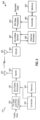
- FIG. 2 shows the generation of an IFDMA symbol for one set of N subbands.
- An original sequence of N modulation symbols to be transmitted in one symbol period on the N subbands in set u is denoted as ⁇ d 1 ,d 2 ,d 3 ,...,d N ⁇ (block 210).
- the original sequence of N modulation symbols is replicated S times to obtain an extended sequence of K modulation symbols (block 212).
- the N modulation symbols are sent in the time domain and collectively occupy N subbands in the frequency domain.
- the S copies of the original sequence result in the N occupied subbands being spaced apart by S subbands, with S-1 subbands of zero power separating adjacent occupied subbands.
- the extended sequence has a comb-like frequency spectrum that occupies subband set 1 in FIG. 1 .
- the extended sequence is multiplied with a phase ramp to obtain a frequency-translated sequence of output symbols (block 214).
- Each output symbol in the frequency-translated sequence may be generated as follows: where d n is the n-th modulation symbol in the extended sequence and x n the n-th output symbol in the frequency-translated sequence.
- the phase ramp e -j2 ⁇ (n-1) ⁇ (u-1)/K ⁇ has a phase slope of 2 ⁇ (u -1) / K, which is determined by the first subband in set u.
- the terms " n -1 " and "u -1" in the exponent of the phase ramp are due to indices n and u starting with '1' instead of '0'.
- the multiplication with the phase ramp in the time domain translates the comb-like frequency spectrum of the extended sequence up in frequency so that the frequency-translated sequence occupies subband set u in the frequency domain.
- the last C output symbols of the frequency-translated sequence are copied to the start of the frequency-translated sequence to form an IFDMA symbol that contains K + C output symbols (block 216).
- the C copied output symbols are often called a cyclic prefix or a guard interval, and C is the cyclic prefix length.
- the cyclic prefix is used to combat intersymbol interference (ISI) caused by frequency selective fading, which is a frequency response that varies across the system bandwidth.
- the K + C output symbols in the IFDMA symbol are transmitted in K+C sample periods, one output symbol in each sample period.
- a symbol period for IFDMA is the duration of one IFDMA symbol and is equal to K + C sample periods.
- a sample period is also often called a chip period.
- the IFDMA symbol Since the IFDMA symbol is periodic in the time domain (except for the phase ramp), the IFDMA symbol occupies a set of N equally spaced subbands starting with subband u. Users with different subband offsets occupy different subband sets and are orthogonal to one another, similar to OFDMA.
- FIG. 3 shows an exemplary narrowband subband structure 300 that may be used for a communication system.
- the K total subbands are arranged into S non-overlapping groups.
- Each group contains N subbands that are adjacent to one another.
- N > 1, S > 1, and K S . N, where N and S for narrowband subband structure 300 may be the same or different from N and S for interlace subband structure 100 in FIG. 1 .
- Group v contains subbands ( v -1) . N + 1, ( v -1) ⁇ N + 2, ..., v ⁇ N, where v is the group index and v ⁇ ⁇ 1,...,S ⁇ .
- a subband structure may include any number of groups, each group may contain any number of subbands, and the groups may contain the same or different numbers of subbands.
- FIG. 4 shows the generation of an LFDMA symbol for one group of N subbands.
- An original sequence of N modulation symbols to be transmitted in one symbol period on the subband group is denoted as ⁇ d 1 ,d 2 ,d 3 ,...,d N ⁇ (block 410).
- the original sequence of N modulation symbols is transformed to the frequency domain with an N-point fast Fourier transform (FFT) to obtain a sequence of N frequency-domain symbols (block 412).
- FFT N-point fast Fourier transform
- the N frequency-domain symbols are mapped onto the N subbands used for transmission and K - N zero symbols are mapped onto the remaining K - N subbands to generate a sequence of K symbols (block 414).
- the N subbands used for transmission have indices of k + 1 through k + N, where 1 ⁇ k ⁇ (K - N) .
- the sequence of K symbols is then transformed to the time domain with a K-point IFFT to obtain a sequence of K time-domain output symbols (block 416).
- the last C output symbols of the sequence are copied to the start of the sequence to form an LFDMA symbol that contains K +C output symbols (block 418).
- the LFDMA symbol is generated such that it occupies a group of N adjacent subbands starting with subband k + 1.
- Users may be assigned with different non-overlapping subband groups and are then orthogonal to one another, similar to OFDMA.
- Each user may be assigned different subband groups in different symbol periods to achieve frequency diversity.
- the subband groups for each user may be selected, e.g., based on a frequency hopping pattern.
- SC-FDMA has certain desirable characteristics such as high spectral efficiency and robustness against multipath effects, similar to OFDMA. Furthermore, SC-FDMA does not have a high PAPR since the modulation symbols are sent in the time domain.
- the PAPR of an SC-FDMA waveform is determined by the signal points in the signal constellation selected for use (e.g., M-PSK, M-QAM, and so on).
- the time-domain modulation symbols in SC-FDMA are prone to intersymbol interference due to a non-flat communication channel.
- Equalization may be performed on the received modulation symbols to mitigate the deleterious effects of intersymbol interference.
- the equalization requires a fairly accurate channel estimate for the communication channel, which may be obtained using the techniques described herein.
- a transmitter may transmit a pilot to facilitate channel estimation by a receiver.
- a pilot is a transmission of symbols that are known a priori by both the transmitter and receiver.
- a data symbol is a modulation symbol for data
- a pilot symbol is a modulation symbol for pilot.
- the data symbols and pilot symbols may be derived from the same or different signal constellations.
- the pilot may be transmitted in various manners, as described below.
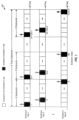
- FIG. 5A shows a TDM pilot scheme 500 with pilot and data being multiplexed across symbol periods.
- data may be sent in D 1 symbol periods, then pilot may be sent in the next P 1 symbol periods, then data may be sent in the next D 1 symbol periods, and so on.
- D 1 > 1 and P 1 1.
- a sequence of N data symbols may be sent on one subband set/group in each symbol period used for data transmission.
- a sequence of N pilot symbols may be sent on one subband set/group in each symbol period used for pilot transmission.
- a sequence of N data or pilot symbols may be converted to an IFDMA symbol or an LFDMA symbol as described above for FIGS.
- An SC-FDMA symbol may be an IFDMA symbol or an LFDMA symbol.
- An SC-FDMA symbol containing only pilot is called a pilot SC-FDMA symbol, which may be a pilot IFDMA symbol or a pilot LFDMA symbol.
- An SC-FDMA symbol containing only data is called a data SC-FDMA symbol, which may be a data IFDMA symbol or a data LFDMA symbol.
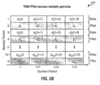
- FIG. 5B shows a TDM pilot scheme 510 with pilot and data being multiplexed across sample periods.
- data and pilot are multiplexed within the same SC-FDMA symbol.
- data symbols may be sent in D 2 sample periods, then pilot symbols may be sent in the next P 2 sample periods, then data symbols are sent in the next D 2 sample periods, and so on.
- a sequence of N data and pilot symbols may be sent on one subband set/group in each symbol period and may be converted to an SC-FDMA symbol as described above for FIGS. 2 and 4 .
- a TDM pilot scheme may also multiplex pilot and data across both symbol periods and sample periods. For example, data and pilot symbols may be sent in some symbol periods, only data symbols may be sent in some other symbol periods, and only pilot symbols may be sent in certain symbol periods.
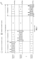
- FIG. 5C shows a CDM pilot scheme 530 with pilot and data being combined across symbol periods.
- a sequence of N data symbols is multiplied with a first M-chip orthogonal sequence ⁇ w d ⁇ to obtain M sequences of scaled data symbols, where M > 1.
- Each sequence of scaled data symbols is obtained by multiplying the original sequence of data symbols with one chip of the orthogonal sequence ⁇ w d ⁇ .
- a sequence of N pilot symbols is multiplied with a second M-chip orthogonal sequence ⁇ w p ⁇ to obtain M sequences of scaled pilot symbols.
- Each sequence of scaled data symbols is then added with a corresponding sequence of scaled pilot symbols to obtain a sequence of combined symbols.
- M sequences of combined symbols are obtained by adding the M sequences of scaled data symbols with the M sequences of scaled pilot symbols.
- Each sequence of combined symbols is converted to an SC-FDMA symbol.
- the orthogonal sequences may be Walsh sequences, OVSF sequences, and so on.
- M 2
- the N data symbols are multiplied by +1 for symbol period t and also by +1 for symbol period t + 1.
- the N pilot symbols are multiplied by +1 for symbol period t and by -1 for symbol period t +1.
- the N scaled data symbols are added with the N scaled pilot symbols to obtain N combined symbols for that symbol period.
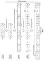
- FIG. 5D shows a CDM pilot scheme 540 with pilot and data being combined across sample periods.
- a sequence of N/M data symbols is multiplied with the M-chip orthogonal sequence ⁇ w d ⁇ to obtain a sequence of N scaled data symbols.
- the first data symbol d 1 (t) in the original sequence is multiplied with the orthogonal sequence ⁇ w d ⁇ to obtain the first M scaled data symbols
- the next data symbol d 2 ( t ) is multiplied with the orthogonal sequence ⁇ w d ⁇ to obtain the next M scaled data symbols
- the last data symbol d N / M ( t ) in the original sequence is multiplied with the orthogonal sequence ⁇ w d ⁇ to obtain the last M scaled data symbols.
- a sequence of N/M pilot symbols is multiplied with the M-chip orthogonal sequence ⁇ w p ⁇ to obtain a sequence of N scaled pilot symbols.
- the sequence of N scaled data symbols is added with the sequence of N scaled pilot symbols to obtain a sequence of N combined symbols, which is converted to an SC-FDMA symbol.
- a sequence of N/2 data symbols is multiplied with the orthogonal sequence ⁇ +1 +1 ⁇ to obtain a sequence of N scaled data symbols.
- a sequence of N/2 pilot symbols is multiplied with the orthogonal sequence ⁇ +1 -1 ⁇ to obtain a sequence of N scaled pilot symbols.
- the N scaled data symbols are added with the N scaled pilot symbols to obtain N combined symbols for that symbol period.
- a CDM pilot may be sent in each symbol period, as shown in FIGS. 5C and 5D .
- a CDM pilot may also be sent only in certain symbol periods.
- a pilot scheme may also use a combination of TDM and CDM. For example, a CDM pilot may be sent in some symbol periods and a TDM pilot may be sent in other symbol periods.
- a frequency division multiplexed (FDM) pilot may also be sent on a designated set of subbands, e.g., for the downlink.
- FDM frequency division multiplexed
- a TDM or CDM pilot is sent on the N subbands used for data transmission.
- the subbands used for pilot transmission may be the same as or different from the subbands used for data transmission (or simply, the data subbands).
- the pilot may also be sent on fewer or more subbands than the data.
- the data and pilot subbands may be static for an entire transmission.
- the data and pilot subbands may hop across frequency in different time slots to achieve frequency diversity.
- a physical channel may be associated with a frequency hopping (FH) pattern that indicates one or more specific subband sets or groups to use for the physical channel in each time slot.
- a time slot may span one or multiple symbol periods.
- FH frequency hopping
- FIG. 6 shows a wideband pilot scheme 600, which may be more applicable for the reverse link.
- each user transmits a wideband pilot, which is a pilot that is sent on all or most of the K total subbands, e.g., all subbands usable for transmission.
- the wideband pilot may be generated in the time domain (e.g., with a pseudo-random number (PN) sequence) or in the frequency domain (e.g., using OFDM).
- PN pseudo-random number
- the wideband pilot for each user may be time division multiplexed with the data transmission from that user, which may be generated using LFDMA (as shown in FIG. 6 ) or IFDMA (not shown in FIG. 6 ).
- the wideband pilots from all users may be transmitted in the same symbol periods, which can avoid interference from data to pilot for channel estimation.
- the wideband pilot from each user may be code division multiplexed (e.g., pseudo-random) with respect to the wideband pilots from other users. This may be achieved by assigning each user with a different PN sequence.
- the wideband pilot for each user has low peak-to-average power ratio (PAPR) and spans the entire system bandwidth, which allows a receiver to derive a wideband channel estimate for the user.
- PAPR peak-to-average power ratio
- the data subbands hop across frequency in different time slots. For each time slot, a channel estimate may be derived for the data subbands based on the wideband pilot.
- FIGS. 5A through 6 show exemplary pilot and data transmission schemes.
- the pilot and data may also be transmitted in other manners using any combination of TDM, CDM, and/or some other multiplexing schemes.
- the TDM and CDM pilots may be generated in various manners.
- the pilot symbols used to generate the TDM and CDM pilots are modulation symbols from a well-known signal constellation such as QPSK.
- a sequence of N modulation symbols may be used for the TDM pilot scheme shown in FIG. 5A and the CDM pilot scheme shown in FIG. 5C .
- a sequence of N/M modulation symbols may be used for the TDM pilot scheme shown in FIG. 5B and the CDM pilot scheme shown in FIG. 5D .
- the sequence of N modulation symbols and the sequence of N / M modulation symbols may each be selected to have (1) a frequency spectrum that is as flat as possible and (2) a temporal envelope that varies as little as possible.
- the flat frequency spectrum ensures that all subbands used for pilot transmission have sufficient power to allow the receiver to properly estimate the channel gains for these subbands.
- the constant envelope avoids distortion by circuit blocks such as a power amplifier.
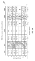
- the pilot symbols used to generate the TDM and CDM pilots are formed based on a polyphase sequence that has good temporal and spectral characteristics.
- Equation (3) is for a Golomb sequence
- equation (4) is for a P3 sequence
- equation (5) is for a P4 sequence
- equation (6) is for a Chu sequence.
- the P3, P4 and Chu sequences can have any arbitrary length.
- Equation (8) is for a Frank sequence
- equation (9) is for a P1 sequence
- equation (10) is for a Px sequence.
- a sequence of pilot symbols generated based on any of the polyphase sequences described above has both a flat frequency spectrum and a constant time-domain envelope.
- Other polyphase sequences having good spectral characteristics (e.g., a flat or known frequency spectrum) and good temporal characteristics (e.g., a constant or known time-domain envelope) may also be used.
- a TDM or CDM pilot generated with this pilot symbol sequence would then have. (1) a low PAPR, which avoids distortion by circuit elements such as a power amplifier, and (2) a flat frequency spectrum, which allows the receiver to accurately estimate the channel gains for all subbands used for pilot transmission.
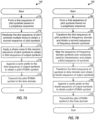
- FIG. 7A shows a process 700 for generating a pilot IFDMA symbol.
- a first sequence of pilot symbols is formed based on a polyphase sequence, which may be any one of the polyphase sequences described above or some other polyphase sequence (block 710).
- the first sequence of pilot symbols is replicated multiple times to obtain a second sequence of pilot symbols (block 712).
- a phase ramp is applied to the second sequence of pilot symbols to obtain a third sequence of output symbols (block 714).
- the phase ramp may be applied digitally on the pilot symbols or accounted for by the frequency upconversion process.
- a cyclic prefix is appended to the third sequence of output symbols to obtain a fourth sequence of output symbols, which is a pilot IFDMA symbol (block 716).
- the pilot IFDMA symbol is transmitted in the time domain via a communication channel (block 718).
- the pilot symbols may be multiplexed with data symbols using TDM and/or CDM, e.g., as described above for FIGS. 5A through 5D .
- FIG. 7B shows a process 750 for generating a pilot LFDMA symbol.
- a first sequence of pilot symbols is formed based on a polyphase sequence, which may be any one of the polyphase sequences described above or some other polyphase sequence (block 760).
- the first sequence of N pilot symbols is transformed to the frequency domain with an N-point FFT to obtain a second sequence of N frequency-domain symbols (block 762).
- the N frequency-domain symbols are then mapped onto N subbands used for pilot transmission and zero symbols are mapped to the remaining K - N subbands to obtain a third sequence of K symbols (block 764).
- the third sequence of K symbols is transformed to the time domain with a K-point IFFT to obtain a fourth sequence of K time-domain output symbols (block 766).
- a cyclic prefix is appended to the fourth sequence of output symbols to obtain a fifth sequence of K + C output symbols, which is a pilot LFDMA symbol (block 768).
- the pilot LFDMA symbol is transmitted in the time domain via a communication channel (block 770).
- the pilot symbols may be multiplexed with data symbols using TDM and/or CDM, e.g., as described above for FIGS. 5A through 5D .
- the number of subbands used for pilot . transmission may be the same or different from the number of subbands used for data transmission. For example, a user may be assigned 16 subbands for data transmission and eight subbands for pilot transmission. The other eight subbands may be assigned to another user for data/pilot transmission. Multiple users may share the same subband set for interlace subband structure 100 in FIG. 1 or the same subband group for narrowband subband structure 300 in FIG. 3 .
- an FDM pilot may be transmitted on one or more subband sets to allow receiver to perform various functions such as, for example, channel estimation, frequency tracking, time tracking, and so on.
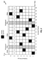
- pilot IFDMA symbols may be transmitted using a staggering pattern of ⁇ 1, 4, 7, 2, 5, 8, 3, 6 ⁇ , so that pilot IFDMA symbols are sent on subband set 1, then on subband set 4, then on subband set 7, and so on. Other staggering patterns may also be used.
- a staggered FDM pilot allows the receiver to obtain channel gain estimates for more subbands, which may improve channel estimation and detection performance.
- FIG. 8 shows a process 800 performed by a receiver to estimate the response of the communication channel based on a TDM pilot or a CDM pilot sent by the transmitter.
- the receiver obtains an SC-FDMA symbol for each symbol period and removes the cyclic prefix in the received SC-FDMA symbol (block 810).
- the receiver removes the phase ramp in the received SC-FDMA symbol.
- the receiver obtains K received data/pilot symbols for the SC-FDMA symbol.
- the receiver then undoes the TDM or CDM performed on the pilot (block 812).
- multiple received pilot symbols are obtained for each SC-FDMA symbol containing the TDM pilot.
- a frequency selective communication channel causes intersymbol interference (ISI).
- ISI intersymbol interference
- the ISI is restricted to within a single SC-FDMA symbol because of the cyclic prefix.
- a linear convolution operation due to the channel impulse response effectively becomes a circular convolution, similar to OFDMA. Therefore, it is possible to perform channel estimation, equalization, and other operations in the frequency domain when pilot symbols and data symbols are not sent in the same SC-FDMA symbol.
- the receiver obtains K received pilot symbols for each pilot transmission.
- the receiver may estimate the channel frequency response using various channel estimation techniques such as an MMSE technique, a least-squares (LS) technique, and so on.
- the receiver derives channel gain estimates for the N pilot subbands based on the N received pilot values and using the MMSE or LS technique (block 818).
- the initial frequency response estimate contains N channel gains for the N pilot subbands.
- the pilot symbol sequence may be generated based on a polyphase sequence having a flat frequency response.
- the impulse response of the communication channel may be characterized by L taps, where L may be much less than N. That is, if an impulse is applied to the communication channel by the transmitter, then L time-domain samples (at the sample rate of BW MHz) would be sufficient to characterize the response of the communication channel based on this impulse stimulus.
- the number of taps (L) for the channel impulse response is dependent on the delay spread of the system, which is the time difference between the earliest and latest arriving signal instances of sufficient energy at the receiver. A longer delay spread corresponds to a larger value for L, and vice versa.
- a channel impulse response estimate may be derived based on the N channel gain estimates and using LS or MMSE technique (block 820).
- An N-point IFFT may also be performed on the initial frequency response estimate to obtain a channel impulse response estimate with N taps.
- Filtering and/or post-processing may be performed on the initial frequency response estimate and/or the channel impulse response estimate to improve the quality of the channel estimate, as described below (block 822).
- a final frequency response estimate for all K subbands may be obtained by (1) zero-padding the L-tap or N-tap channel impulse response estimate to length K and (2) performing a K-point FFT on the extended impulse response estimate (block 824).
- a final frequency response estimate for all K subbands may also be obtained by (1) interpolating the N channel gain estimates, (2) performing least-squares approximation on the N channel gain estimates, or (3) using other approximation techniques.
- a receiver can derive a longer channel impulse response estimate based on a staggered FDM pilot.
- a full-length impulse response estimate with K taps may be obtained if the pilot is transmitted on all S subband sets using a complete staggering pattern.
- the receiver may derive a longer impulse response estimate of length L T by filtering initial impulse response estimates of length N for a sufficient number of different subband sets.
- Each initial impulse response estimate may be derived based on a pilot IFDMA symbol for one subband set. If the pilot is transmitted on a different subband set in each symbol period, then the filtering may be performed over a sufficient number of symbol periods to obtain the longer impulse response estimate.
- filtering may be performed on initial frequency response estimates, least-squares or MMSE channel impulse response estimates, and/or final frequency response estimates obtained for different symbol periods to improve the quality of the channel estimate.
- the filtering may be based on a finite impulse response (FIR) filter, an infinite impulse response (IIR) filter, or some other type of filter.
- FIR finite impulse response
- IIR infinite impulse response
- the filter coefficients may be selected to achieve the desired amount of filtering, which may be selected based on a trade off between various factors such as, e.g., the desired channel estimate quality, the ability to track fast changes in the channel, filter complexity, and so on.
- a frequency response estimate and/or a channel impulse response estimate for the communication channel may also be obtained in other manners using other channel estimation techniques.
- Various post-processing operations may be performed to improve the quality of the channel estimate.
- the communication channel often has only a small number of taps in the time domain.
- the channel estimation described above may provide a channel impulse response estimate having a large number of taps due to noise.
- the post-processing attempts to remove taps that result from noise and retain taps that result from the actual channel.
- truncation In one post-processing scheme, which is called truncation, only the first L taps of the channel impulse response estimate are retained, and the remaining taps are replaced with zeros.
- thresholding taps with low energy are replaced with zeros.
- B best taps of the channel impulse response estimate are retained, where B ⁇ 1, and remaining taps are set to zeros.
- the number of taps to retain may be a fixed or variable value.
- B may be selected based on a received signal-to-noise-and-interference ratio (SNR) for the pilot/data transmission, the spectral efficiency of a data packet for which the channel estimate is used, and/or some other parameter.
- SNR received signal-to-noise-and-interference ratio
- two best taps may be retained if the received SNR is within a first range (e.g., from 0 to 5 decibels (dB)), three best taps may be retained if the received SNR is within a second range (e.g., from 5 to 10 dB), four best taps may be retained if the received SNR is within a third range (e.g., from 10 to 15 dB), and so on.
- a first range e.g., from 0 to 5 decibels (dB)
- three best taps may be retained if the received SNR is within a second range (e.g., from 5 to 10 dB)
- four best taps may be retained if the received SNR is within a third range (e.g., from 10 to 15 dB), and so on.
- Channel estimation may be performed in the time domain for the TDM pilot scheme shown in FIG. 5B , the CDM pilot scheme shown in FIG. 5D , and other pilot schemes in which data and pilot symbols are sent in the same SC-FDMA symbol.
- a rake estimator may be used to identify strong signal paths, for example, by (1) correlating the received symbols with the transmitted pilot symbol sequence at different time offsets and (2) identifying time offsets that provide high correlation results.
- the time domain channel estimation provides a set of taps for a channel impulse response estimate for the communication channel.
- the channel estimation provides a channel impulse response estimate and/or a frequency response estimate that may be used for equalization of the received data symbols.
- a sequence of K received data symbols is obtained for each data SC-FDMA symbol for the TDM pilot scheme shown in FIG. 5A and for each set of M received SC-FDMA symbols for the CDM pilot scheme shown in FIG. 5C .
- the sequence of K received data symbols may be equalized in the time domain or the frequency domain.
- the sequence of K equalized data symbols from equation (24) contains S copies of the transmitted data symbols.
- the accumulation is not performed, and N equalized data symbols for only one copy of the transmitted data are provided as the N data symbol estimates.
- the receiver may also estimate interference based on the received pilot values and the channel estimate.
- the interference estimate I(k) may be averaged over all N subbands for each SC-FDMA symbol to obtain a short-term interference estimate, which may be used for data demodulation and/or other purposes.
- the short-term interference estimate may be averaged over multiple SC-FDMA symbols to obtain a long-term interference estimate, which may be used to estimate operating conditions and/or for other purposes.
- Other techniques may also be used to improve the quality of the channel estimate derived from a TDM pilot or a CDM pilot. These techniques include an iterative channel estimation technique and a data-aided channel estimation technique.
- an initial estimate of the communication channel is first derived based on the received pilot symbols, e.g., using the MMSE or least-squares technique.
- the initial channel estimate is used to derive data symbol estimates, as described above.
- the data symbol estimates are processed to obtain decoded data.
- the decoded data is then processed in the same manner performed at the transmitter to obtain remodulated data symbols, which are convolved with the initial channel estimate to obtain the interference estimate.
- the process may be repeated for any number of iterations to obtain progressively better channel estimates.
- the iterative channel estimation technique is more suited for the TDM pilot scheme shown in FIG. 5B , the CDM pilot schemes shown in FIGS. 5C and 5D , and other pilot schemes in which the data symbols may cause intersymbol interference on the pilot symbols.
- the received data symbols are used along with the received pilot symbols for channel estimation.
- a first channel estimate is derived based on the received pilot symbols and used to obtain data symbol estimates.
- a second channel estimate is then derived based on the received data symbols and the data symbol estimates.
- the received data symbols r d (n) are converted to frequency-domain received data values R d (k)
- the data symbol estimates d ⁇ (n) are converted to frequency-domain data values D ⁇ (k).
- the second channel estimate may be obtained by substituting R d (k) for R p (k) and D ⁇ (k) for P(k) in equations (14) through (18).
- the data symbol estimates are processed to obtain decoded data, and the decoded data is processed to obtain remodulated data symbols D nn (k).
- the second channel estimate may be obtained by substituting R d (k) for R p (k) and D r m ( k ) for P(k) in equations (14) through (18).
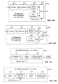
- FIG. 9 shows a block diagram of a transmitter 910 and a receiver 950.
- transmitter 910 is part of a base station and receiver 950 is part of a wireless device.
- transmitter 910 is part of a wireless device and receiver 950 is part of a base station.
- a base station is generally a fixed station and may also be called a base transceiver system (BTS), an access point, or some other terminology.
- BTS base transceiver system
- a wireless device may be fixed or mobile and may also be called a user terminal, a mobile station, or some other terminology.
- a TX data and pilot processor 920 processes traffic data to obtain data symbols, generates pilot symbols, and provides the data symbols and pilot symbols.
- An SC-FDMA modulator 930 multiplexes the data symbols and pilot symbols using TDM and/or CDM and performs SC-FDMA modulation (e.g., for IFDMA, LFDMA, and so on) to generate SC-FDMA symbols.
- a transmitter unit (TMTR) 932 processes (e.g., converts to analog, amplifies, filters, and frequency upconverts) the SC-FDMA symbols and generates a radio frequency (RF) modulated signal, which is transmitted via an antenna 934.
- RF radio frequency
- an antenna 952 receives the transmitted signal and provides a received signal.
- a receiver unit (RCVR) 954 conditions (e.g., filters, amplifies, frequency downconverts, and digitizes) the received signal to generate a stream of received samples.
- An SC-FDMA demodulator 960 processes the received samples and obtains received data symbols and received pilot symbols.
- a channel estimator/ processor 980 derives a channel estimate based on the received pilot symbols.
- SC-FDMA demodulator 960 performs equalization on the received data symbols with the channel estimate and provides data symbol estimates.
- a receive (RX) data processor 970 symbol demaps, deinterleaves, and decodes the data symbol estimates and provides decoded data.
- the processing by SC-FDMA demodulator 960 and RX data processor 970 is complementary to the processing by SC-FDMA modulator 930 and TX data and pilot processor 920, respectively, at transmitter 910.
- Controllers 940 and 990 direct the operation of various processing units at transmitter 910 and receiver 950, respectively.
- Memory units 942 and 992 store program codes and data used by controllers 940 and 990, respectively.
- FIG. 10A shows a block diagram of a TX data and pilot processor 920a, which is an embodiment of processor 920 in FIG. 9 and may be used for the TDM pilot schemes.
- traffic data is encoded by an encoder 1012, interleaved by an interleaver 1014, and mapped to data symbols by a symbol mapper 1016.
- a pilot generator 1020 generates pilot symbols, e.g., based on a polyphase sequence.
- a multiplexer (Mux) 1022 receives and multiplexes the data symbols with the pilot symbols based on a TDM control and provides a stream of multiplexed data and pilot symbols.
- Multiplexer (Mux) 1022 receives and multiplexes the data symbols with the pilot symbols based on a TDM control and provides a stream of multiplexed data and pilot symbols.
- FIG. 10B shows a block diagram of a TX data and pilot processor 920b, which is another embodiment of processor 920 in FIG. 9 and may be used for the CDM pilot schemes.
- traffic data is encoded by encoder 1012, interleaved by interleaver 1014, and mapped to data symbols by symbol mapper 1016.
- a multiplier 1024a multiplies each data symbol with the M chips of the orthogonal sequence ⁇ w d ⁇ for data and provides M scaled data symbols.
- a multiplier 1024b multiplies each pilot symbol with the M chips of the orthogonal sequence ⁇ w p ⁇ for pilot and provides M scaled pilot symbols.
- a summer 1026 sums the scaled data symbols with the scaled pilot symbols, e.g., as shown in FIG. 5C or 5D , and provides combined symbols.
- FIG. 11A shows an SC-FDMA modulator 930a for IFDMA, which is an embodiment of SC-FDMA modulator 930 in FIG. 9 .
- a repetition unit 1112 repeats an original sequence of data/pilot symbols S times to obtain an extended sequence of K symbols.
- a phase ramp unit 1114 applies a phase ramp to the extended symbol sequence to generate a frequency-translated sequence of output symbols. The phase ramp is determined by the subband set u used for transmission.
- a cyclic prefix generator 1116 appends a cyclic prefix to the frequency-translated symbol sequence to generate an IFDMA symbol.
- FIG. 11B shows an SC-FDMA modulator 930b for LFDMA, which is another embodiment of SC-FDMA modulator 930 in FIG. 9 .
- an FFT unit 1122 performs an N-point FFT on an original sequence of data/pilot symbols to obtain a sequence of N frequency-domain symbols.
- a symbol-to-subband-mapper 1124 maps the N frequency-domain symbols onto the N subbands used for transmission and maps K - N zero symbols onto the remaining K - N subbands.
- An IFFT unit 1126 performs a K-point IFFT on the K symbols from mapper 1124 and provides a sequence of K time-domain output symbols.
- a cyclic prefix generator 1128 appends a cyclic prefix to the output symbol sequence to generate an LFDMA symbol.
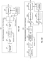
- FIG. 12A shows a block diagram of an SC-FDMA demodulator 960a, which is an embodiment of demodulator 960 in FIG. 9 and may be used for the TDM IFDMA pilot schemes.
- a cyclic prefix removal unit 1212 removes the cyclic prefix for each received IFDMA symbol.
- a phase ramp removal unit 1214 removes the phase ramp in each received IFDMA symbol. The phase ramp removal may also be performed by the frequency downconversion from RF to baseband.
- a demultiplexer (Demux) 1220 receives the output of unit 1214, and provides received data symbols to an equalizer 1230, and provides received pilot symbols to channel estimator 980.
- Channel estimator 980 derives a channel estimate based on the received pilot symbols, e.g., using the MMSE or least-squares technique.
- Equalizer 1230 performs equalization on the received data symbols with the channel estimate in the time domain or the frequency domain and provides equalized data symbols.
- An accumulator 1232 accumulates equalized data symbols corresponding to multiple copies of the same transmitted data symbol and provides data symbol estimates.
- FIG. 12B shows a block diagram of an SC-FDMA demodulator 960b, which is another embodiment of demodulator 960 in FIG. 9 and may be used for the CDM IFDMA pilot schemes.
- SC-FDMA demodulator 960b includes a data channelizer that recovers the transmitted data symbols and a pilot channelizer that recovers the transmitted pilot symbols.
- a multiplier 1224a multiplies the output of unit 1214 with the M chips of the data orthogonal sequence ⁇ w d ⁇ and provides scaled data symbols.
- An accumulator 1226a accumulates M scaled data symbols for each transmitted data symbol and provides a received data symbol.
- a multiplier 1224b multiplies the output of unit 1214 with the M chips of the pilot orthogonal sequence ⁇ w p ⁇ and provides M scaled pilot symbols for each transmitted pilot symbol, which are accumulated by an accumulator 1226b to obtain a received pilot symbol for the transmitted pilot symbol.
- the processing by subsequent units within SC-FDMA demodulator 960b is as described above for SC-FDMA demodulator 960a.
- FIG. 13A shows a block diagram of an SC-FDMA demodulator 960c, which is yet another embodiment of demodulator 960 in FIG. 9 and may be used for the TDM LFDMA pilot schemes.
- a cyclic prefix removal unit 1312 removes the cyclic prefix for each received LFDMA symbol.
- An FFT unit 1314 performs a K-point FFT on an LFDMA symbol after removal of the cyclic prefix and provides K frequency-domain values.
- a subband-to-symbol demapper 1316 receives the K frequency-domain values, provides N frequency-domain values for the N subbands used for transmission, and discards the remaining frequency-domain values.
- An IFFT unit 1318 performs an N-point FFT on the N frequency-domain values from demapper 1316 and provides N received symbols.
- a demultiplexer 1320 receives the output of unit 1318, provides received data symbols to an equalizer 1330, and provides received pilot symbols to channel estimator 980.
- Equalizer 1330 performs equalization on the received data symbols in the time domain or the frequency domain with a channel estimate from channel estimator 980 and provides data symbol estimates.
- FIG. 13B shows a block diagram of an SC-FDMA demodulator 960d, which is yet another embodiment of demodulator 960 in FIG. 9 and may be used for the CDM LFDMA pilot schemes.
- SC-FDMA demodulator 960d includes a data channelizer that recovers the transmitted data symbols and a pilot channelizer that recovers the transmitted pilot symbols.
- a multiplier 1324a multiplies the output of IFFT unit 1318 with the M chips of the data orthogonal sequence ⁇ w d ⁇ and provides scaled data symbols.
- An accumulator 1326a accumulates M scaled data symbols for each transmitted data symbol and provides a received data symbol.
- a multiplier 1324b multiplies the output of IFFT unit 1318 with the M chips of the pilot orthogonal sequence ⁇ w p ⁇ and provides M scaled pilot symbols for each transmitted pilot symbol, which are accumulated by an accumulator 1326b to obtain a received pilot symbol for the transmitted pilot symbol.
- the processing by subsequent units within SC-FDMA demodulator 960d is as described above for SC-FDMA demodulator 960c.
- the pilot transmission and channel estimation techniques described herein may be implemented by various means. For example, these techniques may be implemented in hardware, software, or a combination thereof.
- the processing units used to generate and transmit a pilot at a transmitter may be implemented within one or more application specific integrated circuits (ASICs), digital signal processors (DSPs), digital signal processing devices (DSPDs), programmable logic devices (PLDs), field programmable gate arrays (FPGAs), processors, controllers, micro-controllers, microprocessors, electronic devices, other electronic units designed to perform the functions described herein, or a combination thereof.
- ASICs application specific integrated circuits
- DSPs digital signal processors
- DSPDs digital signal processing devices
- PLDs programmable logic devices
- FPGAs field programmable gate arrays
- processors controllers, micro-controllers, microprocessors, electronic devices, other electronic units designed to perform the functions described herein, or a combination thereof.
- the processing units used to perform channel estimation at a receiver may also
- the techniques may be implemented with modules (e.g., procedures, functions, and so on) that perform the functions described herein.
- the software codes may be stored in a memory unit (e.g., memory unit 942 or 992 in FIG. 9 ) and executed by a processor (e.g., controller 940 or 990).
- the memory unit may be implemented within the processor or external to the processor.
Description
- The present invention relates generally to communication, and more specifically to pilot transmission and channel estimation for a communication system.
- Orthogonal frequency division multiplexing (OFDM) is a multi-carrier modulation technique that partitions the overall system bandwidth into multiple (K) orthogonal subbands. These subbands are also called tones, subcarriers, and frequency bins. With OFDM, each subband is associated with a respective subcarrier that may be modulated with data.
- OFDM has certain desirable characteristics such as high spectral efficiency and robustness against multipath effects. However, a major drawback with OFDM is a high peak-to-average power ratio (PAPR), which means that the ratio of the peak power to the average power of an OFDM waveform can be high. The high PAPR for the OFDM waveform results from possible in-phase (or coherent) addition of all the subcarriers when they are independently modulated with data. In fact, it can be shown that the peak power can be up to K times greater than the average power for OFDM.
- The high PAPR for the OFDM waveform is undesirable and may degrade performance. For example, large peaks in the OFDM waveform may cause a power amplifier to operate in a highly non-linear region or possibly clip, which would then cause intermodulation distortion and other artifacts that can degrade signal quality. The degraded signal quality can adversely affect performance for channel estimation, data detection, and so on.
- The PhD thesis "Interleaved Frequency-Division Multiple-Access" by Isabella de Broeck, Technical University Darmstadt, 2004, discusses IFDMA in general and theoretically investigates different equalization schemes.
-
EP 1414 177 A1 describes apparatus, methods, processor control code and signals for channel estimation in OFDM (Orthogonal Frequency Division Multiplexed) communication systems with a plurality of transmitter antennas, such as MIMO (Multiple-input Multiple-output) OFDM systems. An OFDM signal is transmitted from an OFDM transmitter using a plurality of transmit antennas. The OFDM signal is adapted for channel estimation for channels associated with said transmit antennas by the inclusion of orthogonal training sequence data in the signal from each said antenna. The said training sequence data is derived from substantially orthogonal training sequences of length K for each said transmit antenna, said orthogonal training sequences being constructed such that a minimum required sequence length K needed to determine a channel estimate for at least one channel associated with each said transmit antenna is linearly dependent upon the number of said transmit antennas. - The article "A multiple access scheme for the uplink of broadband wireless systems" by Dinis et al., Global Telecommunications Conference, 2004, Globecom '04, considers SC-based (Single Carrier) block transmission, with all users transmitting continuously, regardless of their data-rate. The transmitted signals can have very low envelope fluctuations. Moreover, the different users remain orthogonal, even for severe time-dispersive channels. By employing IB-DFE techniques (Iterative Block Decision Feedback Equalization) it becomes possible to have detection performances dose to the matched filter bound, and even for fully loaded systems and severe time-dispersive channels.
- 3GPP contribution "Uplink Multiple Access for EUTRA" by Motorola, R1-050245, discusses DFT spread OFDM transmissions with a mapping to an adjacent group of sub-carriers.
- There is still a need to provide techniques that may further improve the transmission quality in multi-carrier modulation.
- The present invention provides a solution according to the independent claims.
- Pilot transmission techniques that can avoid high PAPR and channel estimation techniques are described herein. A pilot may be generated based on a polyphase sequence and using single-carrier frequency division multiple access (SC-FDMA). A polyphase sequence is a sequence that has good temporal characteristics (e.g., a constant time-domain envelope) and good spectral characteristics (e.g., a flat frequency spectrum). SC-FDMA includes (1) interleaved FDMA (IFDMA) which transmits data and/or pilot on subbands that are uniformly spaced apart across the K total subbands and (2) localized FDMA (LFDMA) which transmits data and/or pilot typically on adjacent subbands among the K total subbands. IFDMA is also called distributed FDMA, and LFDMA is also called narrowband FDMA.
- In an embodiment not covered by the claimed invention for pilot transmission using IFDMA, a first sequence of pilot symbols is formed based on a polyphase sequence and is replicated multiple times to obtain a second sequence of pilot symbols. A phase ramp may be applied to the second sequence of pilot symbols to obtain a third sequence of output symbols. A cyclic prefix is appended to the third sequence of output symbols to form an IFDMA symbol, which is transmitted in the time domain via a communication channel. The pilot symbols may be multiplexed with data symbols using time division multiplexing (TDM), code division multiplexing (CDM), and/or some other multiplexing scheme.
- In an embodiment for pilot transmission using LFDMA, a first sequence of pilot symbols is formed based on a polyphase sequence and is transformed to the frequency domain to obtain a second sequence of frequency-domain symbols. A third sequence of symbols is formed with the second sequence of frequency-domain symbols mapped onto a group of subbands used for pilot transmission and zero symbols mapped onto the remaining subbands. The third sequence of symbols is transformed to the time domain to obtain a fourth sequence of output symbols. A cyclic prefix is appended to the fourth sequence of output symbols to form an LFDMA symbol, which is transmitted in the time domain via a communication channel.
- In an embodiment for channel estimation, at least one SC-FDMA symbol is received via the communication channel and processed (e.g., demultiplexed for a TDM pilot or dechannelized for a CDM pilot) to obtain received pilot symbols. An SC-FDMA symbol may be an IFDMA symbol (not covered by the claimed invention) or an LFDMA (claimed invention). A channel estimate is derived based on the received pilot symbols and using a minimum mean-square error (MMSE) technique, a least-squares (LS) technique, or some other channel estimation technique. Filtering, thresholding, truncation, and/or tap selection may be performed to obtain an improved channel estimate. The channel estimate may also be improved by performing iterative channel estimation or data-aided channel estimation.
- Various aspects and embodiments of the invention are described in further detail below.
- The features and nature of the present invention will become more apparent from the detailed description set forth below when taken in conjunction with the drawings in which like reference characters identify correspondingly throughout.
-
FIG. 1 shows an interlace subband structure for a communication system. -
FIG. 2 shows generation of an IFDMA symbol for one set of N subbands. -
FIG. 3 shows a narrowband subband structure. -
FIG. 4 shows generation of an LFDMA symbol for one group of N subbands. -
FIGS. 5A and5B show two TDM pilot schemes with pilot and data being multiplexed across symbol periods and sample periods, respectively. -
FIGS. 5C and 5D show two CDM pilot schemes with pilot and data being combined across symbol periods and sample periods, respectively. -
FIG. 6 shows a wideband pilot time division multiplexed with data. -
FIG. 7A shows a process for generating a pilot IFDMA symbol. -
FIG. 7B shows a process for generating a pilot LFDMA symbol. -
FIG. 8 shows a process for performing channel estimation. -
FIG. 9 shows a block diagram of a transmitter and a receiver. -
FIGS. 10A and 10B show transmit (TX) data and pilot processors for the TDM pilot schemes and the CDM pilot schemes, respectively. -
FIGS. 11A and 11B show IFDMA and LFDMA modulators, respectively. -
FIGS. 12A and 12B show IFDMA demodulators for TDM and CDM pilots, respectively. -
FIGS. 13A and 13B show LFDMA demodulators for TDM and CDM pilots, respectively. - The word "exemplary" is used herein to mean "serving as an example, instance, or illustration." Any embodiment or design described herein as "exemplary" is not necessarily to be construed as preferred or advantageous over other embodiments or designs.
- The pilot transmission and channel estimation techniques described herein may be used for various communication systems that utilize multi-carrier modulation or perform frequency division multiplexing. For example, these techniques may be used for a frequency division multiple access (FDMA) system, an orthogonal frequency division multiple access (OFDMA) system, an SC-FDMA system, an IFDMA system, an LFDMA system, an OFDM-based system, and so on. These techniques may also be used for the forward link (or downlink) and the reverse link (or uplink).
-
FIG. 1 shows anexemplary subband structure 100 that may be used for a communication system. The system has an overall bandwidth of BW MHz, which is partitioned into K orthogonal subbands that are given indices of 1 through K. The spacing between adjacent subbands is BW/K MHz. In a spectrally shaped system, some subbands on both ends of the system bandwidth are not used for data/pilot transmission and serve as guard subbands to allow the system to meet spectral mask requirements. Alternatively, the K subbands may be defined over the usable portion of the system bandwidth. For simplicity, the following description assumes that all K total subbands may be used for data/pilot transmission. - For
subband structure 100, the K total subbands are arranged into S disjoint subband sets, which are also called interlaces. The S sets are disjoint or non-overlapping in that each of the K subbands belongs in only one set. Each set contains N subbands that are uniformly distributed across the K total subbands such that consecutive subbands in the set are spaced apart by S subbands, where K=S·N. Thus, set u contains subbands u, S + u, 2S + u , ..., (N-1)·S+u , where u is the set index and u ∈ {1,...,S}. Index u is also a subband offset that indicates the first subband in the set. The N subbands in each set are interlaced with the N subbands in each of the other S -1 sets. -
FIG. 1 shows a specific subband structure. In general, a subband structure may include any number of subband sets, and each set may include any number of subbands. The sets may include the same or different numbers of subbands. For example, some sets may include N subbands while other sets may include 2N, 4N or some other number of subbands. The subbands in each set are uniformly distributed (i.e., evenly spaced) across the K total subbands in order to achieve the benefits described below. For simplicity, the following description assumes the use ofsubband structure 100 inFIG. 1 . - The S subband sets may be viewed as S channels that may be used for data and pilot transmission. For example, each user may be assigned one subband set, and data and pilot for each user may be sent on the assigned subband set. S users may simultaneously transmit data/pilot on the S subband sets via the reverse link to a base station. The base station may also simultaneously transmit data/pilot on the S subband sets via the forward link to S users. For each link, up to N modulation symbols may be sent in each symbol period (in time or frequency) on the N subbands in each set without causing interference to the other subband sets. A modulation symbol is a complex value for a point in a signal constellation (e.g., for M-PSK, M-QAM, and so on).
- For OFDM, modulation symbols are transmitted in the frequency domain. For each subband set, N modulation symbols may be transmitted on the N subbands in each symbol period. In the following description, a symbol period is the time duration of one OFDM symbol, one IFDMA symbol, or one LFDMA symbol. One modulation symbol is mapped to each of the N subbands used for transmission, and a zero symbol (which is a signal value of zero) is mapped to each of the K - N unused subbands. The K modulation and zero symbols are transformed from the frequency domain to the time domain by performing a K-point inverse fast Fourier transform (IFFT) on the K modulation and zero symbols to obtain K time-domain samples. The time-domain samples can have high PAPR.
-
FIG. 2 shows the generation of an IFDMA symbol for one set of N subbands. An original sequence of N modulation symbols to be transmitted in one symbol period on the N subbands in set u is denoted as {d 1,d2,d3,...,dN } (block 210). The original sequence of N modulation symbols is replicated S times to obtain an extended sequence of K modulation symbols (block 212). The N modulation symbols are sent in the time domain and collectively occupy N subbands in the frequency domain. The S copies of the original sequence result in the N occupied subbands being spaced apart by S subbands, with S-1 subbands of zero power separating adjacent occupied subbands. The extended sequence has a comb-like frequency spectrum that occupies subband set 1 inFIG. 1 . - The extended sequence is multiplied with a phase ramp to obtain a frequency-translated sequence of output symbols (block 214). Each output symbol in the frequency-translated sequence may be generated as follows:

- The last C output symbols of the frequency-translated sequence are copied to the start of the frequency-translated sequence to form an IFDMA symbol that contains K + C output symbols (block 216). The C copied output symbols are often called a cyclic prefix or a guard interval, and C is the cyclic prefix length. The cyclic prefix is used to combat intersymbol interference (ISI) caused by frequency selective fading, which is a frequency response that varies across the system bandwidth. The K + C output symbols in the IFDMA symbol are transmitted in K+C sample periods, one output symbol in each sample period. A symbol period for IFDMA is the duration of one IFDMA symbol and is equal to K + C sample periods. A sample period is also often called a chip period.
- Since the IFDMA symbol is periodic in the time domain (except for the phase ramp), the IFDMA symbol occupies a set of N equally spaced subbands starting with subband u. Users with different subband offsets occupy different subband sets and are orthogonal to one another, similar to OFDMA.
-
FIG. 3 shows an exemplarynarrowband subband structure 300 that may be used for a communication system. Forsubband structure 300, the K total subbands are arranged into S non-overlapping groups. Each group contains N subbands that are adjacent to one another. In general, N > 1, S > 1, and K =S . N, where N and S fornarrowband subband structure 300 may be the same or different from N and S forinterlace subband structure 100 inFIG. 1 . Group v contains subbands (v -1) . N + 1, (v -1)·N + 2, ..., v·N, where v is the group index and v ∈ {1,...,S}. In general, a subband structure may include any number of groups, each group may contain any number of subbands, and the groups may contain the same or different numbers of subbands. -
FIG. 4 shows the generation of an LFDMA symbol for one group of N subbands. An original sequence of N modulation symbols to be transmitted in one symbol period on the subband group is denoted as {d1,d2,d3,...,dN } (block 410). The original sequence of N modulation symbols is transformed to the frequency domain with an N-point fast Fourier transform (FFT) to obtain a sequence of N frequency-domain symbols (block 412). The N frequency-domain symbols are mapped onto the N subbands used for transmission and K - N zero symbols are mapped onto the remaining K - N subbands to generate a sequence of K symbols (block 414). The N subbands used for transmission have indices of k + 1 through k + N, where 1 ≤ k ≤ (K - N) . The sequence of K symbols is then transformed to the time domain with a K-point IFFT to obtain a sequence of K time-domain output symbols (block 416). The last C output symbols of the sequence are copied to the start of the sequence to form an LFDMA symbol that contains K +C output symbols (block 418). - The LFDMA symbol is generated such that it occupies a group of N adjacent subbands starting with
subband k + 1. Users may be assigned with different non-overlapping subband groups and are then orthogonal to one another, similar to OFDMA. Each user may be assigned different subband groups in different symbol periods to achieve frequency diversity. The subband groups for each user may be selected, e.g., based on a frequency hopping pattern. - SC-FDMA has certain desirable characteristics such as high spectral efficiency and robustness against multipath effects, similar to OFDMA. Furthermore, SC-FDMA does not have a high PAPR since the modulation symbols are sent in the time domain. The PAPR of an SC-FDMA waveform is determined by the signal points in the signal constellation selected for use (e.g., M-PSK, M-QAM, and so on). However, the time-domain modulation symbols in SC-FDMA are prone to intersymbol interference due to a non-flat communication channel. Equalization may be performed on the received modulation symbols to mitigate the deleterious effects of intersymbol interference. The equalization requires a fairly accurate channel estimate for the communication channel, which may be obtained using the techniques described herein.
- A transmitter may transmit a pilot to facilitate channel estimation by a receiver. A pilot is a transmission of symbols that are known a priori by both the transmitter and receiver. As used herein, a data symbol is a modulation symbol for data, and a pilot symbol is a modulation symbol for pilot. The data symbols and pilot symbols may be derived from the same or different signal constellations. The pilot may be transmitted in various manners, as described below.
-
FIG. 5A shows aTDM pilot scheme 500 with pilot and data being multiplexed across symbol periods. For example, data may be sent in D1 symbol periods, then pilot may be sent in the next P1 symbol periods, then data may be sent in the next D1 symbol periods, and so on. In general D1 ≥ 1 and P1 ≥ 1. For the example shown inFIG. 5A , D1 > 1 and P1 = 1. A sequence of N data symbols may be sent on one subband set/group in each symbol period used for data transmission. A sequence of N pilot symbols may be sent on one subband set/group in each symbol period used for pilot transmission. For each symbol period, a sequence of N data or pilot symbols may be converted to an IFDMA symbol or an LFDMA symbol as described above forFIGS. 2 and4 , respectively. An SC-FDMA symbol may be an IFDMA symbol or an LFDMA symbol. An SC-FDMA symbol containing only pilot is called a pilot SC-FDMA symbol, which may be a pilot IFDMA symbol or a pilot LFDMA symbol. An SC-FDMA symbol containing only data is called a data SC-FDMA symbol, which may be a data IFDMA symbol or a data LFDMA symbol. -
FIG. 5B shows aTDM pilot scheme 510 with pilot and data being multiplexed across sample periods. For this embodiment, data and pilot are multiplexed within the same SC-FDMA symbol. For example, data symbols may be sent in D2 sample periods, then pilot symbols may be sent in the next P2 sample periods, then data symbols are sent in the next D2 sample periods, and so on. In general D2 ≥ 1 and P2 ≥ 1. For the example shown inFIG. 5B , D2 = 1 and P2 = 1. A sequence of N data and pilot symbols may be sent on one subband set/group in each symbol period and may be converted to an SC-FDMA symbol as described above forFIGS. 2 and4 . - A TDM pilot scheme may also multiplex pilot and data across both symbol periods and sample periods. For example, data and pilot symbols may be sent in some symbol periods, only data symbols may be sent in some other symbol periods, and only pilot symbols may be sent in certain symbol periods.
-
FIG. 5C shows aCDM pilot scheme 530 with pilot and data being combined across symbol periods. For this embodiment, a sequence of N data symbols is multiplied with a first M-chip orthogonal sequence {wd } to obtain M sequences of scaled data symbols, where M > 1. Each sequence of scaled data symbols is obtained by multiplying the original sequence of data symbols with one chip of the orthogonal sequence {wd }. Similarly, a sequence of N pilot symbols is multiplied with a second M-chip orthogonal sequence {wp } to obtain M sequences of scaled pilot symbols. Each sequence of scaled data symbols is then added with a corresponding sequence of scaled pilot symbols to obtain a sequence of combined symbols. M sequences of combined symbols are obtained by adding the M sequences of scaled data symbols with the M sequences of scaled pilot symbols. Each sequence of combined symbols is converted to an SC-FDMA symbol. - The orthogonal sequences may be Walsh sequences, OVSF sequences, and so on. For the example shown in
FIG. 5C , M = 2, the first orthogonal sequence is {wd } = {+1 +1}, and the second orthogonal sequence is {wp } = {+1 -1}. The N data symbols are multiplied by +1 for symbol period t and also by +1 for symbol period t + 1. The N pilot symbols are multiplied by +1 for symbol period t and by -1 for symbol period t+1. For each symbol period, the N scaled data symbols are added with the N scaled pilot symbols to obtain N combined symbols for that symbol period. -
FIG. 5D shows aCDM pilot scheme 540 with pilot and data being combined across sample periods. For this embodiment, a sequence of N/M data symbols is multiplied with the M-chip orthogonal sequence {wd } to obtain a sequence of N scaled data symbols. In particular, the first data symbol d1(t) in the original sequence is multiplied with the orthogonal sequence {wd } to obtain the first M scaled data symbols, the next data symbol d 2(t) is multiplied with the orthogonal sequence {wd } to obtain the next M scaled data symbols, and so on, and the last data symbol d N/M (t) in the original sequence is multiplied with the orthogonal sequence {wd } to obtain the last M scaled data symbols. Similarly, a sequence of N/M pilot symbols is multiplied with the M-chip orthogonal sequence {wp } to obtain a sequence of N scaled pilot symbols. The sequence of N scaled data symbols is added with the sequence of N scaled pilot symbols to obtain a sequence of N combined symbols, which is converted to an SC-FDMA symbol. - For the example shown in
FIG. 5D , M = 2, the orthogonal sequence for data is {wd } = {+1 +1}, and the orthogonal sequence for pilot is {wp } = {+1 -1}. A sequence of N/2 data symbols is multiplied with the orthogonal sequence {+1 +1} to obtain a sequence of N scaled data symbols. Similarly, a sequence of N/2 pilot symbols is multiplied with the orthogonal sequence {+1 -1} to obtain a sequence of N scaled pilot symbols. For each symbol period, the N scaled data symbols are added with the N scaled pilot symbols to obtain N combined symbols for that symbol period. - A CDM pilot may be sent in each symbol period, as shown in
FIGS. 5C and 5D . A CDM pilot may also be sent only in certain symbol periods. A pilot scheme may also use a combination of TDM and CDM. For example, a CDM pilot may be sent in some symbol periods and a TDM pilot may be sent in other symbol periods. A frequency division multiplexed (FDM) pilot may also be sent on a designated set of subbands, e.g., for the downlink. - For the embodiments shown in
FIGS. 5A through 5D , a TDM or CDM pilot is sent on the N subbands used for data transmission. In general, the subbands used for pilot transmission (or simply, the pilot subbands) may be the same as or different from the subbands used for data transmission (or simply, the data subbands). The pilot may also be sent on fewer or more subbands than the data. The data and pilot subbands may be static for an entire transmission. Alternatively, the data and pilot subbands may hop across frequency in different time slots to achieve frequency diversity. For example, a physical channel may be associated with a frequency hopping (FH) pattern that indicates one or more specific subband sets or groups to use for the physical channel in each time slot. A time slot may span one or multiple symbol periods. -
FIG. 6 shows awideband pilot scheme 600, which may be more applicable for the reverse link. For this embodiment, each user transmits a wideband pilot, which is a pilot that is sent on all or most of the K total subbands, e.g., all subbands usable for transmission. The wideband pilot may be generated in the time domain (e.g., with a pseudo-random number (PN) sequence) or in the frequency domain (e.g., using OFDM). The wideband pilot for each user may be time division multiplexed with the data transmission from that user, which may be generated using LFDMA (as shown inFIG. 6 ) or IFDMA (not shown inFIG. 6 ). The wideband pilots from all users may be transmitted in the same symbol periods, which can avoid interference from data to pilot for channel estimation. The wideband pilot from each user may be code division multiplexed (e.g., pseudo-random) with respect to the wideband pilots from other users. This may be achieved by assigning each user with a different PN sequence. The wideband pilot for each user has low peak-to-average power ratio (PAPR) and spans the entire system bandwidth, which allows a receiver to derive a wideband channel estimate for the user. For the embodiment shown inFIG. 6 , the data subbands hop across frequency in different time slots. For each time slot, a channel estimate may be derived for the data subbands based on the wideband pilot. -
FIGS. 5A through 6 show exemplary pilot and data transmission schemes. The pilot and data may also be transmitted in other manners using any combination of TDM, CDM, and/or some other multiplexing schemes. - The TDM and CDM pilots may be generated in various manners. In an embodiment, the pilot symbols used to generate the TDM and CDM pilots are modulation symbols from a well-known signal constellation such as QPSK. A sequence of N modulation symbols may be used for the TDM pilot scheme shown in
FIG. 5A and the CDM pilot scheme shown inFIG. 5C . A sequence of N/M modulation symbols may be used for the TDM pilot scheme shown inFIG. 5B and the CDM pilot scheme shown inFIG. 5D . The sequence of N modulation symbols and the sequence of N / M modulation symbols may each be selected to have (1) a frequency spectrum that is as flat as possible and (2) a temporal envelope that varies as little as possible. The flat frequency spectrum ensures that all subbands used for pilot transmission have sufficient power to allow the receiver to properly estimate the channel gains for these subbands. The constant envelope avoids distortion by circuit blocks such as a power amplifier. - In another embodiment, the pilot symbols used to generate the TDM and CDM pilots are formed based on a polyphase sequence that has good temporal and spectral characteristics. For example, the pilot symbols may be generated as follows:


- The pilot symbols may also be generated as follows:


- A sequence of pilot symbols generated based on any of the polyphase sequences described above has both a flat frequency spectrum and a constant time-domain envelope. Other polyphase sequences having good spectral characteristics (e.g., a flat or known frequency spectrum) and good temporal characteristics (e.g., a constant or known time-domain envelope) may also be used. A TDM or CDM pilot generated with this pilot symbol sequence would then have. (1) a low PAPR, which avoids distortion by circuit elements such as a power amplifier, and (2) a flat frequency spectrum, which allows the receiver to accurately estimate the channel gains for all subbands used for pilot transmission.
-
FIG. 7A shows aprocess 700 for generating a pilot IFDMA symbol. A first sequence of pilot symbols is formed based on a polyphase sequence, which may be any one of the polyphase sequences described above or some other polyphase sequence (block 710). The first sequence of pilot symbols is replicated multiple times to obtain a second sequence of pilot symbols (block 712). A phase ramp is applied to the second sequence of pilot symbols to obtain a third sequence of output symbols (block 714). The phase ramp may be applied digitally on the pilot symbols or accounted for by the frequency upconversion process. A cyclic prefix is appended to the third sequence of output symbols to obtain a fourth sequence of output symbols, which is a pilot IFDMA symbol (block 716). The pilot IFDMA symbol is transmitted in the time domain via a communication channel (block 718). Although not shown inFIG. 7A for simplicity, the pilot symbols may be multiplexed with data symbols using TDM and/or CDM, e.g., as described above forFIGS. 5A through 5D . -
FIG. 7B shows aprocess 750 for generating a pilot LFDMA symbol. A first sequence of pilot symbols is formed based on a polyphase sequence, which may be any one of the polyphase sequences described above or some other polyphase sequence (block 760). The first sequence of N pilot symbols is transformed to the frequency domain with an N-point FFT to obtain a second sequence of N frequency-domain symbols (block 762). The N frequency-domain symbols are then mapped onto N subbands used for pilot transmission and zero symbols are mapped to the remaining K - N subbands to obtain a third sequence of K symbols (block 764). The third sequence of K symbols is transformed to the time domain with a K-point IFFT to obtain a fourth sequence of K time-domain output symbols (block 766). A cyclic prefix is appended to the fourth sequence of output symbols to obtain a fifth sequence of K + C output symbols, which is a pilot LFDMA symbol (block 768). The pilot LFDMA symbol is transmitted in the time domain via a communication channel (block 770). Although not shown inFIG. 7B for simplicity, the pilot symbols may be multiplexed with data symbols using TDM and/or CDM, e.g., as described above forFIGS. 5A through 5D . - For both IFDMA and LFDMA, the number of subbands used for pilot . transmission may be the same or different from the number of subbands used for data transmission. For example, a user may be assigned 16 subbands for data transmission and eight subbands for pilot transmission. The other eight subbands may be assigned to another user for data/pilot transmission. Multiple users may share the same subband set for
interlace subband structure 100 inFIG. 1 or the same subband group fornarrowband subband structure 300 inFIG. 3 . - For
interlace subband structure 100 inFIG. 1 , an FDM pilot may be transmitted on one or more subband sets to allow receiver to perform various functions such as, for example, channel estimation, frequency tracking, time tracking, and so on. In a first staggered FDM pilot, pilot IFDMA symbols are transmitted on subband set p in some symbol periods and on subband set p +S/2 in other symbol periods. For example, if S = 8, then pilot IFDMA symbols may be transmitted using a staggering pattern of {3, 7}, so that pilot IFDMA symbols are sent onsubband set 3, then onsubband set 7, then onsubband set 3, and so on. In a second staggered FDM pilot, pilot IFDMA symbols are transmitted on subband set p(t) = [p(r -1) + Δp] mod S + 1 in symbol period t, where Δp is the difference between subband set indices for two consecutive symbol periods, and the +1 is for an indexing scheme that starts with 1 instead of 0. For example, if S = 8 and Δp = 3, then pilot IFDMA symbols may be transmitted using a staggering pattern of {1, 4, 7, 2, 5, 8, 3, 6}, so that pilot IFDMA symbols are sent onsubband set 1, then onsubband set 4, then onsubband set 7, and so on. Other staggering patterns may also be used. A staggered FDM pilot allows the receiver to obtain channel gain estimates for more subbands, which may improve channel estimation and detection performance. -
FIG. 8 shows aprocess 800 performed by a receiver to estimate the response of the communication channel based on a TDM pilot or a CDM pilot sent by the transmitter. The receiver obtains an SC-FDMA symbol for each symbol period and removes the cyclic prefix in the received SC-FDMA symbol (block 810). For IFDMA, the receiver removes the phase ramp in the received SC-FDMA symbol. For both IFDMA and LFDMA, the receiver obtains K received data/pilot symbols for the SC-FDMA symbol. - The receiver then undoes the TDM or CDM performed on the pilot (block 812). For the TDM pilot scheme shown in
FIG. 5A , K received pilot symbols, rp (n) for n = 1, ...,K, are obtained for each pilot SC-FDMA symbol. For the TDM pilot scheme shown inFIG. 5B , multiple received pilot symbols are obtained for each SC-FDMA symbol containing the TDM pilot. - For the CDM pilot scheme shown in
FIG. 5C , M received SC-FDMA symbols containing the CDM pilot are processed to recover the pilot symbols, as follows:
- r(ti,n) is a received sample for sample period n in symbol period ti;
- wp,i is the i-th chip of the orthogonal sequence for the pilot; and
- rp (n) is a received pilot symbol for sample period n.
- For the CDM pilot scheme shown in
FIG. 5D , each received SC-FDMA symbol containing the CDM pilot are processed to recover the pilot symbols, as follows:
- A frequency selective communication channel causes intersymbol interference (ISI). However, the ISI is restricted to within a single SC-FDMA symbol because of the cyclic prefix. Furthermore, because of the cyclic prefix, a linear convolution operation due to the channel impulse response effectively becomes a circular convolution, similar to OFDMA. Therefore, it is possible to perform channel estimation, equalization, and other operations in the frequency domain when pilot symbols and data symbols are not sent in the same SC-FDMA symbol.
- For the TDM scheme shown in
FIG. 5A and the CDM scheme shown inFIG. 5C , the receiver obtains K received pilot symbols for each pilot transmission. A K-point FFT may be performed on the K received pilot symbols, rp(n) for n = 1,...,K, to obtain K received pilot values in the frequency domain, Rp(k) for k = 1,..., K (block 814). The received pilot values may be given as:
- P(k) is the transmitted pilot value for subband k;
- H(k) is the complex gain for the communication channel for subband k;
- Rp(k) is the received pilot values for subband k; and
- N(k) is the noise for subband k.
- The receiver may estimate the channel frequency response using various channel estimation techniques such as an MMSE technique, a least-squares (LS) technique, and so on. The receiver derives channel gain estimates for the N pilot subbands based on the N received pilot values and using the MMSE or LS technique (block 818). For the MMSE technique, an initial frequency response estimate for the communication channel may be derived based on the received pilot values, as follows:


constant factor 1/(1+N 0) may be removed to provide an unbiased MMSE frequency response estimate, which may be expressed as:
- For the LS technique, an initial frequency response estimate may be derived based on the received pilot values, as follows:

- The impulse response of the communication channel may be characterized by L taps, where L may be much less than N. That is, if an impulse is applied to the communication channel by the transmitter, then L time-domain samples (at the sample rate of BW MHz) would be sufficient to characterize the response of the communication channel based on this impulse stimulus. The number of taps (L) for the channel impulse response is dependent on the delay spread of the system, which is the time difference between the earliest and latest arriving signal instances of sufficient energy at the receiver. A longer delay spread corresponds to a larger value for L, and vice versa.
- A channel impulse response estimate may be derived based on the N channel gain estimates and using LS or MMSE technique (block 820). A least-squares channel impulse response estimate with L taps, ĥls(n) for η =1,..., L, may be derived based on the initial frequency response estimate, as follows:

-

- WN×L is a sub-matrix of a Fourier matrix W K×K ;
-

- "H" denotes a conjugate transpose.
- An MMSE channel impulse response estimate with L taps, ĥ mmse(n) for n = 1, ..., L, may be derived based on the initial frequency response estimate, as follows:


- Filtering and/or post-processing may be performed on the initial frequency response estimate and/or the channel impulse response estimate to improve the quality of the channel estimate, as described below (block 822). A final frequency response estimate for all K subbands may be obtained by (1) zero-padding the L-tap or N-tap channel impulse response estimate to length K and (2) performing a K-point FFT on the extended impulse response estimate (block 824). A final frequency response estimate for all K subbands may also be obtained by (1) interpolating the N channel gain estimates, (2) performing least-squares approximation on the N channel gain estimates, or (3) using other approximation techniques.
- A receiver can derive a longer channel impulse response estimate based on a staggered FDM pilot. In general, a channel impulse response estimate with LT taps may be obtained based on pilot IFDMA symbols sent on LT different subbands in one or more symbol periods. For example, if LT = 2N, then an impulse response estimate with 2N taps may be obtained based on two or more pilot IFDMA symbols sent on two or more subband sets in two or more symbol periods. A full-length impulse response estimate with K taps may be obtained if the pilot is transmitted on all S subband sets using a complete staggering pattern.
- The receiver may derive a longer impulse response estimate of length LT by filtering initial impulse response estimates of length N for a sufficient number of different subband sets. Each initial impulse response estimate may be derived based on a pilot IFDMA symbol for one subband set. If the pilot is transmitted on a different subband set in each symbol period, then the filtering may be performed over a sufficient number of symbol periods to obtain the longer impulse response estimate.
- For SC-FDMA, filtering may be performed on initial frequency response estimates, least-squares or MMSE channel impulse response estimates, and/or final frequency response estimates obtained for different symbol periods to improve the quality of the channel estimate. The filtering may be based on a finite impulse response (FIR) filter, an infinite impulse response (IIR) filter, or some other type of filter. The filter coefficients may be selected to achieve the desired amount of filtering, which may be selected based on a trade off between various factors such as, e.g., the desired channel estimate quality, the ability to track fast changes in the channel, filter complexity, and so on.
- A frequency response estimate and/or a channel impulse response estimate for the communication channel may also be obtained in other manners using other channel estimation techniques.
- Various post-processing operations may be performed to improve the quality of the channel estimate. In certain operating environments, such as a multipath fading environment, the communication channel often has only a small number of taps in the time domain. The channel estimation described above may provide a channel impulse response estimate having a large number of taps due to noise. The post-processing attempts to remove taps that result from noise and retain taps that result from the actual channel.
- In one post-processing scheme, which is called truncation, only the first L taps of the channel impulse response estimate are retained, and the remaining taps are replaced with zeros. In another post-processing scheme, which is called thresholding, taps with low energy are replaced with zeros. In an embodiment, the thresholding is performed as follows:

- ĥ(n) is the n-th tap of the channel impulse response estimate, which may be equal to ĥmmse(n) or ĥls(n) ; and
- hth is the threshold used to zero out low energy taps.
- In yet another post-processing scheme, which is called tap selection, B best taps of the channel impulse response estimate are retained, where B ≥ 1, and remaining taps are set to zeros. The number of taps to retain (denoted as B) may be a fixed or variable value. B may be selected based on a received signal-to-noise-and-interference ratio (SNR) for the pilot/data transmission, the spectral efficiency of a data packet for which the channel estimate is used, and/or some other parameter. For example, two best taps may be retained if the received SNR is within a first range (e.g., from 0 to 5 decibels (dB)), three best taps may be retained if the received SNR is within a second range (e.g., from 5 to 10 dB), four best taps may be retained if the received SNR is within a third range (e.g., from 10 to 15 dB), and so on.
- Channel estimation may be performed in the time domain for the TDM pilot scheme shown in
FIG. 5B , the CDM pilot scheme shown inFIG. 5D , and other pilot schemes in which data and pilot symbols are sent in the same SC-FDMA symbol. A rake estimator may be used to identify strong signal paths, for example, by (1) correlating the received symbols with the transmitted pilot symbol sequence at different time offsets and (2) identifying time offsets that provide high correlation results. The time domain channel estimation provides a set of taps for a channel impulse response estimate for the communication channel. - For all pilot schemes, the channel estimation provides a channel impulse response estimate and/or a frequency response estimate that may be used for equalization of the received data symbols. A sequence of K received data symbols is obtained for each data SC-FDMA symbol for the TDM pilot scheme shown in
FIG. 5A and for each set of M received SC-FDMA symbols for the CDM pilot scheme shown inFIG. 5C . The sequence of K received data symbols may be equalized in the time domain or the frequency domain. - Frequency-domain equalization may be performed as follows. A K-point FFT is first performed on the K received data symbols, rd (n) for n = 1, ..., K , to obtain K frequency-domain received data values, Rd(k) for k = 1,...,K. Only N received data values for the N subbands used for data transmission are retained, and the remaining K—N received data values are discarded. The retained data values are denoted as Rd(k) for k = 1,...,N.
- Equalization may be performed in the frequency domain on the N received data values using the MMSE technique, as follows:

- Rd(k) is the received data value for subband k;
- Ĥ(k) is the channel gain estimate for subband k, which may be equal to Ĥmmse (k) or Ĥls(k); and
- Zd (k) is the equalized data value for subband k.
- Equalization may also be performed in the frequency domain on the N received data values using the zero-forcing technique, as follows:

- For both MMSE and zero-forcing equalization, the N equalized data values, Zd(k) for k = 1,...,N, may be transformed back to the time domain to obtain a sequence of N data symbol estimates, d̂(n) for n = 1,..., N, which are estimates of the N data symbols in the original sequence.
- Equalization may also be performed in the time domain on the sequence of K received data symbols, as follows:

- rd(n) denotes the sequence of K received data symbols;
- g(n) denotes an impulse response of a time-domain equalizer;
- zd (n) denotes a sequence of K equalized data symbols; and
- ⊗ denotes a circular convolution operation.
- The sequence of K equalized data symbols from equation (24) contains S copies of the transmitted data symbols. The S copies may be accumulated on a data symbol-by-data symbol basis to obtain N data symbol estimates, as follows:

- The receiver may also estimate interference based on the received pilot values and the channel estimate. For example, the interference for each subband may be estimated as follows:

- Other techniques may also be used to improve the quality of the channel estimate derived from a TDM pilot or a CDM pilot. These techniques include an iterative channel estimation technique and a data-aided channel estimation technique.
- For the iterative channel estimation technique, an initial estimate of the communication channel is first derived based on the received pilot symbols, e.g., using the MMSE or least-squares technique. The initial channel estimate is used to derive data symbol estimates, as described above. In an embodiment, the interference due to the data symbols on the pilot symbols is estimated based on the data symbol estimates d̂(n) and the initial channel estimate ĥ(n), e.g., as î(n) = d̂(n)⊗ĥ(n), where î(n) denotes the interference estimate. In another embodiment, the data symbol estimates are processed to obtain decoded data. The decoded data is then processed in the same manner performed at the transmitter to obtain remodulated data symbols, which are convolved with the initial channel estimate to obtain the interference estimate. For both embodiments, the interference estimate is subtracted from the received pilot symbols to obtain interference-canceled pilot symbols,

FIG. 5B , the CDM pilot schemes shown inFIGS. 5C and 5D , and other pilot schemes in which the data symbols may cause intersymbol interference on the pilot symbols. - For the data-aided channel estimation technique, the received data symbols are used along with the received pilot symbols for channel estimation. A first channel estimate is derived based on the received pilot symbols and used to obtain data symbol estimates. A second channel estimate is then derived based on the received data symbols and the data symbol estimates. In an embodiment, the received data symbols rd (n) are converted to frequency-domain received data values Rd(k), and the data symbol estimates d̂(n) are converted to frequency-domain data values D̂(k). The second channel estimate may be obtained by substituting Rd(k) for Rp(k) and D̂(k) for P(k) in equations (14) through (18). In another embodiment, the data symbol estimates are processed to obtain decoded data, and the decoded data is processed to obtain remodulated data symbols Dnn(k). The second channel estimate may be obtained by substituting Rd (k) for Rp(k) and D rm (k) for P(k) in equations (14) through (18).
- The two channel estimates obtained with the received pilot symbols and the received data symbols are combined to obtain an improved overall channel estimate. This combining may be performed, for example, as follows:

- Ĥ pilot(k) is the channel estimate obtained based on the received pilot symbols;
- Ĥdata (k) is the channel estimate obtained based on the received data symbols;
- Cp (k) and Cd (k) are weighting factors for pilot and data, respectively; and
- Ĥoverall (k) is the overall channel estimate.
-
FIG. 9 shows a block diagram of atransmitter 910 and areceiver 950. For the forward link,transmitter 910 is part of a base station andreceiver 950 is part of a wireless device. For the reverse link,transmitter 910 is part of a wireless device andreceiver 950 is part of a base station. A base station is generally a fixed station and may also be called a base transceiver system (BTS), an access point, or some other terminology. A wireless device may be fixed or mobile and may also be called a user terminal, a mobile station, or some other terminology. - At
transmitter 910, a TX data andpilot processor 920 processes traffic data to obtain data symbols, generates pilot symbols, and provides the data symbols and pilot symbols. An SC-FDMA modulator 930 multiplexes the data symbols and pilot symbols using TDM and/or CDM and performs SC-FDMA modulation (e.g., for IFDMA, LFDMA, and so on) to generate SC-FDMA symbols. A transmitter unit (TMTR) 932 processes (e.g., converts to analog, amplifies, filters, and frequency upconverts) the SC-FDMA symbols and generates a radio frequency (RF) modulated signal, which is transmitted via anantenna 934. - At
receiver 950, anantenna 952 receives the transmitted signal and provides a received signal. A receiver unit (RCVR) 954 conditions (e.g., filters, amplifies, frequency downconverts, and digitizes) the received signal to generate a stream of received samples. An SC-FDMA demodulator 960 processes the received samples and obtains received data symbols and received pilot symbols. A channel estimator/processor 980 derives a channel estimate based on the received pilot symbols. SC-FDMA demodulator 960 performs equalization on the received data symbols with the channel estimate and provides data symbol estimates. A receive (RX)data processor 970 symbol demaps, deinterleaves, and decodes the data symbol estimates and provides decoded data. In general, the processing by SC-FDMA demodulator 960 andRX data processor 970 is complementary to the processing by SC-FDMA modulator 930 and TX data andpilot processor 920, respectively, attransmitter 910. -
Controllers transmitter 910 andreceiver 950, respectively.Memory units controllers -
FIG. 10A shows a block diagram of a TX data andpilot processor 920a, which is an embodiment ofprocessor 920 inFIG. 9 and may be used for the TDM pilot schemes. Withinprocessor 920a, traffic data is encoded by anencoder 1012, interleaved by aninterleaver 1014, and mapped to data symbols by asymbol mapper 1016. Apilot generator 1020 generates pilot symbols, e.g., based on a polyphase sequence. A multiplexer (Mux) 1022 receives and multiplexes the data symbols with the pilot symbols based on a TDM control and provides a stream of multiplexed data and pilot symbols. -
FIG. 10B shows a block diagram of a TX data andpilot processor 920b, which is another embodiment ofprocessor 920 inFIG. 9 and may be used for the CDM pilot schemes. Withinprocessor 920b, traffic data is encoded byencoder 1012, interleaved byinterleaver 1014, and mapped to data symbols bysymbol mapper 1016. Amultiplier 1024a multiplies each data symbol with the M chips of the orthogonal sequence {wd } for data and provides M scaled data symbols. Similarly, amultiplier 1024b multiplies each pilot symbol with the M chips of the orthogonal sequence {wp } for pilot and provides M scaled pilot symbols. Asummer 1026 sums the scaled data symbols with the scaled pilot symbols, e.g., as shown inFIG. 5C or 5D , and provides combined symbols. -
FIG. 11A shows an SC-FDMA modulator 930a for IFDMA, which is an embodiment of SC-FDMA modulator 930 inFIG. 9 . Withinmodulator 930a, arepetition unit 1112 repeats an original sequence of data/pilot symbols S times to obtain an extended sequence of K symbols. A phase ramp unit 1114 applies a phase ramp to the extended symbol sequence to generate a frequency-translated sequence of output symbols. The phase ramp is determined by the subband set u used for transmission. Acyclic prefix generator 1116 appends a cyclic prefix to the frequency-translated symbol sequence to generate an IFDMA symbol. -
FIG. 11B shows an SC-FDMA modulator 930b for LFDMA, which is another embodiment of SC-FDMA modulator 930 inFIG. 9 . Withinmodulator 930b, anFFT unit 1122 performs an N-point FFT on an original sequence of data/pilot symbols to obtain a sequence of N frequency-domain symbols. A symbol-to-subband-mapper 1124 maps the N frequency-domain symbols onto the N subbands used for transmission and maps K - N zero symbols onto the remaining K - N subbands. AnIFFT unit 1126 performs a K-point IFFT on the K symbols frommapper 1124 and provides a sequence of K time-domain output symbols. Acyclic prefix generator 1128 appends a cyclic prefix to the output symbol sequence to generate an LFDMA symbol. -
FIG. 12A shows a block diagram of an SC-FDMA demodulator 960a, which is an embodiment ofdemodulator 960 inFIG. 9 and may be used for the TDM IFDMA pilot schemes. Within SC-FDMA demodulator 960a, a cyclicprefix removal unit 1212 removes the cyclic prefix for each received IFDMA symbol. A phaseramp removal unit 1214 removes the phase ramp in each received IFDMA symbol. The phase ramp removal may also be performed by the frequency downconversion from RF to baseband. A demultiplexer (Demux) 1220 receives the output ofunit 1214, and provides received data symbols to anequalizer 1230, and provides received pilot symbols tochannel estimator 980.Channel estimator 980 derives a channel estimate based on the received pilot symbols, e.g., using the MMSE or least-squares technique.Equalizer 1230 performs equalization on the received data symbols with the channel estimate in the time domain or the frequency domain and provides equalized data symbols. Anaccumulator 1232 accumulates equalized data symbols corresponding to multiple copies of the same transmitted data symbol and provides data symbol estimates. -
FIG. 12B shows a block diagram of an SC-FDMA demodulator 960b, which is another embodiment ofdemodulator 960 inFIG. 9 and may be used for the CDM IFDMA pilot schemes. SC-FDMA demodulator 960b includes a data channelizer that recovers the transmitted data symbols and a pilot channelizer that recovers the transmitted pilot symbols. For the data channelizer, amultiplier 1224a multiplies the output ofunit 1214 with the M chips of the data orthogonal sequence {wd } and provides scaled data symbols. Anaccumulator 1226a accumulates M scaled data symbols for each transmitted data symbol and provides a received data symbol. For the pilot channelizer, amultiplier 1224b multiplies the output ofunit 1214 with the M chips of the pilot orthogonal sequence {wp } and provides M scaled pilot symbols for each transmitted pilot symbol, which are accumulated by anaccumulator 1226b to obtain a received pilot symbol for the transmitted pilot symbol. The processing by subsequent units within SC-FDMA demodulator 960b is as described above for SC-FDMA demodulator 960a. -
FIG. 13A shows a block diagram of an SC-FDMA demodulator 960c, which is yet another embodiment ofdemodulator 960 inFIG. 9 and may be used for the TDM LFDMA pilot schemes. Within SC-FDMA demodulator 960c, a cyclicprefix removal unit 1312 removes the cyclic prefix for each received LFDMA symbol. AnFFT unit 1314 performs a K-point FFT on an LFDMA symbol after removal of the cyclic prefix and provides K frequency-domain values. A subband-to-symbol demapper 1316 receives the K frequency-domain values, provides N frequency-domain values for the N subbands used for transmission, and discards the remaining frequency-domain values. AnIFFT unit 1318 performs an N-point FFT on the N frequency-domain values fromdemapper 1316 and provides N received symbols. Ademultiplexer 1320 receives the output ofunit 1318, provides received data symbols to anequalizer 1330, and provides received pilot symbols tochannel estimator 980.Equalizer 1330 performs equalization on the received data symbols in the time domain or the frequency domain with a channel estimate fromchannel estimator 980 and provides data symbol estimates. -
FIG. 13B shows a block diagram of an SC-FDMA demodulator 960d, which is yet another embodiment ofdemodulator 960 inFIG. 9 and may be used for the CDM LFDMA pilot schemes. SC-FDMA demodulator 960d includes a data channelizer that recovers the transmitted data symbols and a pilot channelizer that recovers the transmitted pilot symbols. For the data channelizer, amultiplier 1324a multiplies the output ofIFFT unit 1318 with the M chips of the data orthogonal sequence {wd } and provides scaled data symbols. Anaccumulator 1326a accumulates M scaled data symbols for each transmitted data symbol and provides a received data symbol. For the pilot channelizer, amultiplier 1324b multiplies the output ofIFFT unit 1318 with the M chips of the pilot orthogonal sequence {wp } and provides M scaled pilot symbols for each transmitted pilot symbol, which are accumulated by anaccumulator 1326b to obtain a received pilot symbol for the transmitted pilot symbol. The processing by subsequent units within SC-FDMA demodulator 960d is as described above for SC-FDMA demodulator 960c. - The pilot transmission and channel estimation techniques described herein may be implemented by various means. For example, these techniques may be implemented in hardware, software, or a combination thereof. For a hardware implementation, the processing units used to generate and transmit a pilot at a transmitter (e.g., each of the processing units shown in
FIGS. 9 through 13B , or a combination of the processing units) may be implemented within one or more application specific integrated circuits (ASICs), digital signal processors (DSPs), digital signal processing devices (DSPDs), programmable logic devices (PLDs), field programmable gate arrays (FPGAs), processors, controllers, micro-controllers, microprocessors, electronic devices, other electronic units designed to perform the functions described herein, or a combination thereof. The processing units used to perform channel estimation at a receiver may also be implemented within one or more ASICs, DSPs, electronic devices, and so on. - For a software implementation, the techniques may be implemented with modules (e.g., procedures, functions, and so on) that perform the functions described herein. The software codes may be stored in a memory unit (e.g.,
memory unit FIG. 9 ) and executed by a processor (e.g.,controller 940 or 990). The memory unit may be implemented within the processor or external to the processor.

Claims (2)
- An apparatus (910), configured to:generate one or more pilot symbols based on a polyphase sequence;form a sequence of data symbols and to perform multiplexing of the sequence of data symbols and the one or more of pilot symbols;generate at least one single-carrier frequency division multiple access, SC-FDMA, symbol based on the multiplexed sequence of data symbols and the one or more pilot symbols, wherein each of the at least one SC-FDMA symbol includes a cyclic prefix, wherein the at least one SC-FDMA symbol is based on localized FDMA, LFDMA; andtransmit the at least one SC-FDMA symbol using frequency resources assigned to the apparatus (910), wherein the apparatus (910) is assigned different groups of subbands in different symbol periods, such that the groups of subbands hop across frequency in different time slots according to a frequency hopping pattern, wherein a time slot spans one symbol period and wherein the frequency resources comprise a group of adjacent subbands assigned to the apparatus (910).
- The apparatus (910) of claim 1, further configured to assign different non-overlapping groups of subbands to different apparatuses (910).
Priority Applications (1)
| Application Number | Priority Date | Filing Date | Title |
|---|---|---|---|
| SI200632429T SI2961075T1 (en) | 2005-03-07 | 2006-03-07 | Pilot transmission and channel estimation for a communication system utilizing frequency division multiplexing |
Applications Claiming Priority (5)
| Application Number | Priority Date | Filing Date | Title |
|---|---|---|---|
| US65952605P | 2005-03-07 | 2005-03-07 | |
| US11/175,607 US8135088B2 (en) | 2005-03-07 | 2005-07-05 | Pilot transmission and channel estimation for a communication system utilizing frequency division multiplexing |
| EP20100011616 EP2262120A3 (en) | 2005-03-07 | 2006-03-07 | Pilot transmission and channel estimation for a communication system utilizing frequency division multiplexing |
| EP06737468.6A EP1867063B1 (en) | 2005-03-07 | 2006-03-07 | Pilot transmission and channel estimation for a communication system utilizing frequency division multiplexing |
| PCT/US2006/008300 WO2006096784A1 (en) | 2005-03-07 | 2006-03-07 | Pilot transmission and channel estimation for a communication system utilizing frequency division multiplexing |
Related Parent Applications (2)
| Application Number | Title | Priority Date | Filing Date |
|---|---|---|---|
| EP06737468.6A Division EP1867063B1 (en) | 2005-03-07 | 2006-03-07 | Pilot transmission and channel estimation for a communication system utilizing frequency division multiplexing |
| EP20100011616 Division EP2262120A3 (en) | 2005-03-07 | 2006-03-07 | Pilot transmission and channel estimation for a communication system utilizing frequency division multiplexing |
Publications (2)
| Publication Number | Publication Date |
|---|---|
| EP2961075A1 EP2961075A1 (en) | 2015-12-30 |
| EP2961075B1 true EP2961075B1 (en) | 2023-06-07 |
Family
ID=36570641
Family Applications (4)
| Application Number | Title | Priority Date | Filing Date |
|---|---|---|---|
| EP15170466.5A Active EP2961075B1 (en) | 2005-03-07 | 2006-03-07 | Pilot transmission and channel estimation for a communication system utilizing frequency division multiplexing |
| EP20100011616 Ceased EP2262120A3 (en) | 2005-03-07 | 2006-03-07 | Pilot transmission and channel estimation for a communication system utilizing frequency division multiplexing |
| EP06737468.6A Active EP1867063B1 (en) | 2005-03-07 | 2006-03-07 | Pilot transmission and channel estimation for a communication system utilizing frequency division multiplexing |
| EP10011615.1A Active EP2262119B1 (en) | 2005-03-07 | 2006-03-07 | Pilot transmissionfor a communication system utilizing frequency division multiplexing |
Family Applications After (3)
| Application Number | Title | Priority Date | Filing Date |
|---|---|---|---|
| EP20100011616 Ceased EP2262120A3 (en) | 2005-03-07 | 2006-03-07 | Pilot transmission and channel estimation for a communication system utilizing frequency division multiplexing |
| EP06737468.6A Active EP1867063B1 (en) | 2005-03-07 | 2006-03-07 | Pilot transmission and channel estimation for a communication system utilizing frequency division multiplexing |
| EP10011615.1A Active EP2262119B1 (en) | 2005-03-07 | 2006-03-07 | Pilot transmissionfor a communication system utilizing frequency division multiplexing |
Country Status (26)
| Country | Link |
|---|---|
| US (2) | US8135088B2 (en) |
| EP (4) | EP2961075B1 (en) |
| JP (7) | JP2008536359A (en) |
| KR (3) | KR100940165B1 (en) |
| CN (3) | CN102664854A (en) |
| AR (1) | AR052587A1 (en) |
| AU (1) | AU2006220558B2 (en) |
| BR (1) | BRPI0608895A2 (en) |
| CA (2) | CA2600152C (en) |
| CL (2) | CL2009000106A1 (en) |
| DK (2) | DK2961075T3 (en) |
| ES (3) | ES2424132T3 (en) |
| FI (1) | FI2961075T3 (en) |
| HU (1) | HUE062242T2 (en) |
| IL (2) | IL185697A (en) |
| MX (1) | MX2007011025A (en) |
| MY (1) | MY154982A (en) |
| NO (1) | NO337478B1 (en) |
| NZ (1) | NZ561173A (en) |
| PL (2) | PL2961075T3 (en) |
| PT (2) | PT1867063E (en) |
| RU (1) | RU2387097C2 (en) |
| SG (1) | SG160367A1 (en) |
| SI (1) | SI2961075T1 (en) |
| TW (3) | TWI530114B (en) |
| WO (1) | WO2006096784A1 (en) |
Families Citing this family (151)
| Publication number | Priority date | Publication date | Assignee | Title |
|---|---|---|---|---|
| US7295509B2 (en) | 2000-09-13 | 2007-11-13 | Qualcomm, Incorporated | Signaling method in an OFDM multiple access system |
| US9130810B2 (en) | 2000-09-13 | 2015-09-08 | Qualcomm Incorporated | OFDM communications methods and apparatus |
| US10355720B2 (en) | 2001-04-26 | 2019-07-16 | Genghiscomm Holdings, LLC | Distributed software-defined radio |
| US10931338B2 (en) | 2001-04-26 | 2021-02-23 | Genghiscomm Holdings, LLC | Coordinated multipoint systems |
| US9628231B2 (en) | 2002-05-14 | 2017-04-18 | Genghiscomm Holdings, LLC | Spreading and precoding in OFDM |
| US10644916B1 (en) | 2002-05-14 | 2020-05-05 | Genghiscomm Holdings, LLC | Spreading and precoding in OFDM |
| US7042857B2 (en) | 2002-10-29 | 2006-05-09 | Qualcom, Incorporated | Uplink pilot and signaling transmission in wireless communication systems |
| US7177297B2 (en) * | 2003-05-12 | 2007-02-13 | Qualcomm Incorporated | Fast frequency hopping with a code division multiplexed pilot in an OFDMA system |
| CN1961498B (en) * | 2003-08-08 | 2012-04-18 | 北方电讯网络有限公司 | Communication signal equalization systems and methods |
| KR100575959B1 (en) * | 2003-09-02 | 2006-05-02 | 삼성전자주식회사 | Apparatus and method for transmitting/receiving pilot in a communication system using multi carrier modulation scheme |
| US8611283B2 (en) | 2004-01-28 | 2013-12-17 | Qualcomm Incorporated | Method and apparatus of using a single channel to provide acknowledgement and assignment messages |
| WO2006001019A2 (en) * | 2004-06-28 | 2006-01-05 | Zion Hadad | Ofmda preambles system and method |
| US8000268B2 (en) * | 2004-06-30 | 2011-08-16 | Motorola Mobility, Inc. | Frequency-hopped IFDMA communication system |
| JP4409395B2 (en) * | 2004-07-13 | 2010-02-03 | 富士通株式会社 | Propagation path estimation method and estimation apparatus |
| US9137822B2 (en) | 2004-07-21 | 2015-09-15 | Qualcomm Incorporated | Efficient signaling over access channel |
| US9148256B2 (en) | 2004-07-21 | 2015-09-29 | Qualcomm Incorporated | Performance based rank prediction for MIMO design |
| US8891349B2 (en) | 2004-07-23 | 2014-11-18 | Qualcomm Incorporated | Method of optimizing portions of a frame |
| US11552737B1 (en) | 2004-08-02 | 2023-01-10 | Genghiscomm Holdings, LLC | Cooperative MIMO |
| US11381285B1 (en) | 2004-08-02 | 2022-07-05 | Genghiscomm Holdings, LLC | Transmit pre-coding |
| US11184037B1 (en) | 2004-08-02 | 2021-11-23 | Genghiscomm Holdings, LLC | Demodulating and decoding carrier interferometry signals |
| US8831115B2 (en) | 2004-12-22 | 2014-09-09 | Qualcomm Incorporated | MC-CDMA multiplexing in an orthogonal uplink |
| US8238923B2 (en) | 2004-12-22 | 2012-08-07 | Qualcomm Incorporated | Method of using shared resources in a communication system |
| US8135088B2 (en) | 2005-03-07 | 2012-03-13 | Q1UALCOMM Incorporated | Pilot transmission and channel estimation for a communication system utilizing frequency division multiplexing |
| US9246560B2 (en) | 2005-03-10 | 2016-01-26 | Qualcomm Incorporated | Systems and methods for beamforming and rate control in a multi-input multi-output communication systems |
| US9154211B2 (en) | 2005-03-11 | 2015-10-06 | Qualcomm Incorporated | Systems and methods for beamforming feedback in multi antenna communication systems |
| US8446892B2 (en) | 2005-03-16 | 2013-05-21 | Qualcomm Incorporated | Channel structures for a quasi-orthogonal multiple-access communication system |
| US9143305B2 (en) | 2005-03-17 | 2015-09-22 | Qualcomm Incorporated | Pilot signal transmission for an orthogonal frequency division wireless communication system |
| US9461859B2 (en) | 2005-03-17 | 2016-10-04 | Qualcomm Incorporated | Pilot signal transmission for an orthogonal frequency division wireless communication system |
| US9520972B2 (en) | 2005-03-17 | 2016-12-13 | Qualcomm Incorporated | Pilot signal transmission for an orthogonal frequency division wireless communication system |
| US9184870B2 (en) | 2005-04-01 | 2015-11-10 | Qualcomm Incorporated | Systems and methods for control channel signaling |
| US7787546B2 (en) * | 2005-04-06 | 2010-08-31 | Samsung Electronics Co., Ltd. | Apparatus and method for FT pre-coding of data to reduce PAPR in a multi-carrier wireless network |
| US9036538B2 (en) * | 2005-04-19 | 2015-05-19 | Qualcomm Incorporated | Frequency hopping design for single carrier FDMA systems |
| US9408220B2 (en) | 2005-04-19 | 2016-08-02 | Qualcomm Incorporated | Channel quality reporting for adaptive sectorization |
| KR101100199B1 (en) * | 2005-05-02 | 2011-12-28 | 엘지전자 주식회사 | method of band limiting for IFDMA commnuication system |
| KR100724949B1 (en) | 2005-05-03 | 2007-06-04 | 삼성전자주식회사 | Method and Apparatus for multiplexing data and control information in wireless communication systems based on frequency division multiple access |
| US20060262874A1 (en) * | 2005-05-17 | 2006-11-23 | Interdigital Technology Corporation | Method and apparatus for power control in a multiple antenna system |
| US8565194B2 (en) | 2005-10-27 | 2013-10-22 | Qualcomm Incorporated | Puncturing signaling channel for a wireless communication system |
| US8611284B2 (en) | 2005-05-31 | 2013-12-17 | Qualcomm Incorporated | Use of supplemental assignments to decrement resources |
| US8879511B2 (en) | 2005-10-27 | 2014-11-04 | Qualcomm Incorporated | Assignment acknowledgement for a wireless communication system |
| US8462859B2 (en) | 2005-06-01 | 2013-06-11 | Qualcomm Incorporated | Sphere decoding apparatus |
| US9179319B2 (en) | 2005-06-16 | 2015-11-03 | Qualcomm Incorporated | Adaptive sectorization in cellular systems |
| US8599945B2 (en) * | 2005-06-16 | 2013-12-03 | Qualcomm Incorporated | Robust rank prediction for a MIMO system |
| JP2007006264A (en) * | 2005-06-24 | 2007-01-11 | Toshiba Corp | Diversity receiver |
| JP4753737B2 (en) * | 2005-07-18 | 2011-08-24 | 三洋電機株式会社 | Wireless device |
| US20070183386A1 (en) * | 2005-08-03 | 2007-08-09 | Texas Instruments Incorporated | Reference Signal Sequences and Multi-User Reference Signal Sequence Allocation |
| US8885628B2 (en) * | 2005-08-08 | 2014-11-11 | Qualcomm Incorporated | Code division multiplexing in a single-carrier frequency division multiple access system |
| US8331216B2 (en) * | 2005-08-09 | 2012-12-11 | Qualcomm Incorporated | Channel and interference estimation in single-carrier and multi-carrier frequency division multiple access systems |
| US9209956B2 (en) | 2005-08-22 | 2015-12-08 | Qualcomm Incorporated | Segment sensitive scheduling |
| US20070041457A1 (en) | 2005-08-22 | 2007-02-22 | Tamer Kadous | Method and apparatus for providing antenna diversity in a wireless communication system |
| US8644292B2 (en) | 2005-08-24 | 2014-02-04 | Qualcomm Incorporated | Varied transmission time intervals for wireless communication system |
| US9136974B2 (en) | 2005-08-30 | 2015-09-15 | Qualcomm Incorporated | Precoding and SDMA support |
| US9210651B2 (en) | 2005-10-27 | 2015-12-08 | Qualcomm Incorporated | Method and apparatus for bootstraping information in a communication system |
| US9088384B2 (en) | 2005-10-27 | 2015-07-21 | Qualcomm Incorporated | Pilot symbol transmission in wireless communication systems |
| US9144060B2 (en) | 2005-10-27 | 2015-09-22 | Qualcomm Incorporated | Resource allocation for shared signaling channels |
| US8582509B2 (en) | 2005-10-27 | 2013-11-12 | Qualcomm Incorporated | Scalable frequency band operation in wireless communication systems |
| US8693405B2 (en) | 2005-10-27 | 2014-04-08 | Qualcomm Incorporated | SDMA resource management |
| US9225416B2 (en) | 2005-10-27 | 2015-12-29 | Qualcomm Incorporated | Varied signaling channels for a reverse link in a wireless communication system |
| US8045512B2 (en) | 2005-10-27 | 2011-10-25 | Qualcomm Incorporated | Scalable frequency band operation in wireless communication systems |
| US9225488B2 (en) | 2005-10-27 | 2015-12-29 | Qualcomm Incorporated | Shared signaling channel |
| US9172453B2 (en) | 2005-10-27 | 2015-10-27 | Qualcomm Incorporated | Method and apparatus for pre-coding frequency division duplexing system |
| US8477684B2 (en) | 2005-10-27 | 2013-07-02 | Qualcomm Incorporated | Acknowledgement of control messages in a wireless communication system |
| KR101306696B1 (en) | 2005-11-10 | 2013-09-10 | 엘지전자 주식회사 | apparatus and method for transmitting data using a plurality of carriers |
| US8582548B2 (en) | 2005-11-18 | 2013-11-12 | Qualcomm Incorporated | Frequency division multiple access schemes for wireless communication |
| JP5111392B2 (en) * | 2005-12-08 | 2013-01-09 | コーニンクレッカ フィリップス エレクトロニクス エヌ ヴィ | System, apparatus and method for single carrier block transmission with adaptive guard interval |
| US8831607B2 (en) | 2006-01-05 | 2014-09-09 | Qualcomm Incorporated | Reverse link other sector communication |
| US7808886B2 (en) * | 2006-01-18 | 2010-10-05 | Freescale Semiconductor, Inc. | Pilot signal in an FDMA communication system |
| CN101375570B (en) * | 2006-01-20 | 2014-06-25 | 高通股份有限公司 | Method and apparatus for pilot multiplexing in a wireless communication system |
| US8130857B2 (en) * | 2006-01-20 | 2012-03-06 | Qualcomm Incorporated | Method and apparatus for pilot multiplexing in a wireless communication system |
| KR100966942B1 (en) * | 2006-01-24 | 2010-06-30 | 닛본 덴끼 가부시끼가이샤 | Transmission path estimation device, equalization device, and radio system |
| US8094709B2 (en) * | 2006-02-01 | 2012-01-10 | Nec Corporation | Equalizer and equalization method |
| US20070201569A1 (en) * | 2006-02-08 | 2007-08-30 | Nokia Corporation | Apparatus, method and computer program product providing joint detection for increasing throughout with data in uplink that multiplexes users using codes and that multiplexes users using frequency multiplexing |
| EP2016683A4 (en) * | 2006-04-27 | 2014-07-16 | Texas Instruments Inc | Methods and apparatus to allocate reference signals in wireless communication systems |
| EP2045940B1 (en) * | 2006-07-25 | 2017-10-11 | Fujitsu Limited | Interference noise estimating method in multicarrier communication system and interference noise estimating device |
| US20080025377A1 (en) * | 2006-07-25 | 2008-01-31 | Legend Silicon | Method and device for frequency domain compensation for channel estimation at an over sampling rate in a tds_ofdm receiver |
| KR101188544B1 (en) | 2006-09-15 | 2012-10-05 | 엘지전자 주식회사 | Data Transmission Method for Single Carrier-Frequency Division Multiple Access System and Pilot Allocation Method |
| FI20065689A0 (en) * | 2006-10-31 | 2006-10-31 | Nokia Corp | Data sequence structure and transfer procedure |
| EP2369803B1 (en) * | 2006-11-01 | 2013-08-28 | Qualcomm Incorporated | Joint use of multi-carrier and single-carrier multiplexing schemes for wireless communication |
| UA96959C2 (en) | 2006-11-01 | 2011-12-26 | Квелкомм Інкорпорейтед | Multiplexing of control and data with varying power offsets in a sc-fdma system |
| US8027395B2 (en) * | 2006-11-03 | 2011-09-27 | Maxlinear, Inc. | Edge MMSE filters |
| KR100862724B1 (en) * | 2006-12-06 | 2008-10-10 | 한국전자통신연구원 | Apparatus and method for transceiver pilot signal of wireless communication system |
| US8130875B2 (en) * | 2006-12-11 | 2012-03-06 | Cisco Technology, Inc. | Method for estimating channel response in a wireless communications network based on pilot signals |
| US7693031B2 (en) * | 2007-01-09 | 2010-04-06 | Futurewei Technologies, Inc. | Method and apparatus for achieving system acquisition and other signaling purposes using the preamble in an OFDM based communications system |
| WO2008091951A2 (en) * | 2007-01-23 | 2008-07-31 | Polytechnic University | Hybrid subcarrier mapping method and system |
| FI20075198A0 (en) * | 2007-03-27 | 2007-03-27 | Nokia Corp | Frequency correction |
| KR101414962B1 (en) * | 2007-04-27 | 2014-07-07 | 삼성전자주식회사 | Method for transmitting and receiving uplink channel sounding reference signals in wireless communication systems |
| WO2008133449A1 (en) | 2007-04-27 | 2008-11-06 | Samsung Electronics Co., Ltd. | Method and apparatus for transmitting and receiving uplink channel sounding reference signals in a wireless communication system |
| EP2151107B1 (en) * | 2007-05-09 | 2018-03-21 | Telefonaktiebolaget LM Ericsson (publ) | Receiver for a radio network and an method for determining a channel estimate for a radio channel |
| EP1993248A1 (en) * | 2007-05-16 | 2008-11-19 | Nokia Siemens Networks Oy | Method for coding data and data coding device |
| US8750917B2 (en) * | 2007-05-18 | 2014-06-10 | Qualcomm Incorporated | Multiplexing and power control of uplink control channels in a wireless communication system |
| KR101481820B1 (en) * | 2007-06-20 | 2015-01-12 | 삼성전자주식회사 | Method and Apparatus for Transmitting Uplink Control Channel in Mobile Communication System |
| US8145272B2 (en) * | 2007-08-08 | 2012-03-27 | Cisco Technology, Inc. | Pilot-based two-dimensional channel estimation |
| US9363126B2 (en) * | 2007-12-21 | 2016-06-07 | Google Technology Holdings LLC | Method and apparatus for IFDMA receiver architecture |
| KR101456299B1 (en) * | 2008-02-11 | 2014-11-03 | 엘지전자 주식회사 | Method of interleaving in wireless communication system |
| US8457258B2 (en) * | 2008-02-25 | 2013-06-04 | Indian Institute Of Technology | Optimal training sequence and channel estimation method and system for superimposed training based OFDM systems |
| EP2549816A1 (en) | 2008-03-19 | 2013-01-23 | NEC Corporation | Wireless communication system, wireless communication setting method, base station, mobile station, and program |
| US8699529B2 (en) * | 2008-03-28 | 2014-04-15 | Qualcomm Incorporated | Broadband pilot channel estimation using a reduced order FFT and a hardware interpolator |
| US8509325B2 (en) * | 2008-07-01 | 2013-08-13 | Qualcomm Incorporated | Adaptive thresholding for OFDM channel estimation |
| TWI382728B (en) * | 2008-07-07 | 2013-01-11 | Inst Information Industry | Base station, subordinated station and transmission method thereof |
| US8208858B2 (en) * | 2008-07-30 | 2012-06-26 | Kan Ling Capital, L.L.C. | Polyphase sequences for wireless communications |
| US8730933B2 (en) * | 2008-09-18 | 2014-05-20 | Qualcomm Incorporated | Method and apparatus for multiplexing data and reference signal in a wireless communication system |
| US8249509B2 (en) * | 2008-11-24 | 2012-08-21 | Cisco Technology, Inc. | Dynamic channel estimation based on channel conditions |
| GB2474794B (en) | 2008-11-27 | 2011-06-15 | Ipwireless Inc | Communication system, communication units, and method for employing a pilot transmission scheme |
| CN101753498B (en) * | 2008-12-05 | 2013-02-13 | 中兴通讯股份有限公司 | Method for filtering orthogonal frequency division multiplexing channel estimation results and the device thereof |
| US8275057B2 (en) * | 2008-12-19 | 2012-09-25 | Intel Corporation | Methods and systems to estimate channel frequency response in multi-carrier signals |
| US9762414B2 (en) * | 2009-02-04 | 2017-09-12 | Acorn Technologies, Inc. | Least squares channel identification for OFDM Systems |
| US8761274B2 (en) * | 2009-02-04 | 2014-06-24 | Acorn Technologies, Inc. | Least squares channel identification for OFDM systems |
| US8804859B2 (en) * | 2009-02-23 | 2014-08-12 | Mediatek, Inc. | Methods and apparatuses for dealing with spectrum inversion |
| US9288026B2 (en) | 2009-06-22 | 2016-03-15 | Qualcomm Incorporated | Transmission of reference signal on non-contiguous clusters of resources |
| RU2510132C2 (en) * | 2009-09-04 | 2014-03-20 | Нек Корпорейшн | Radio communication device having carrier phase noise elimination function and radio communication method |
| US8867445B2 (en) * | 2009-11-30 | 2014-10-21 | Optis Wireless Technology, Llc | Bit soft value normalization |
| KR101619164B1 (en) * | 2009-12-16 | 2016-05-10 | 삼성전자주식회사 | Method and apparatus for receiving minimum mean-squared-error in single-carrier frequency division multiple access system |
| WO2011113097A2 (en) * | 2010-03-19 | 2011-09-22 | Ofidium Pty Ltd | Method and apparatus for fiber non-linearity mitigation |
| US8743987B2 (en) * | 2010-08-31 | 2014-06-03 | Optis Cellular Technology, Llc | Symbol detection for alleviating inter-symbol interference |
| JP5579551B2 (en) * | 2010-09-10 | 2014-08-27 | シャープ株式会社 | Receiving device, receiving method and program |
| US8462613B2 (en) * | 2010-12-09 | 2013-06-11 | Hong Kong Applied Science and Technology Research Institute Company Limited | Channel estimation for long term evolution (LTE) terminals |
| US8958323B2 (en) * | 2011-03-19 | 2015-02-17 | Samsung Electronics Co., Ltd. | Communication system with signal processing mechanism for tone estimation and method of operation thereof |
| US8718210B2 (en) * | 2011-09-20 | 2014-05-06 | Qualcomm Incorporated | Channel impulse response estimation for wireless receiver |
| RU2012102842A (en) | 2012-01-27 | 2013-08-10 | ЭлЭсАй Корпорейшн | INCREASE DETECTION OF THE PREAMBLE |
| KR102015680B1 (en) * | 2011-10-27 | 2019-08-28 | 인텔 코포레이션 | Direct digital synthesis of signals using maximum likelihood bit-stream encoding |
| US9531447B2 (en) * | 2011-12-22 | 2016-12-27 | Lattice Semiconductor Corporation | Collaborative channel sounding in multi-antenna systems |
| US8688062B2 (en) * | 2012-04-09 | 2014-04-01 | Harris Corporation | Wireless communications system with interference mitigation and associated methods |
| US9008049B2 (en) | 2012-09-11 | 2015-04-14 | Qualcomm Incorporated | Forward link frame generation in a machine-to-machine (M2M) wireless wide area network (WAN) |
| US8737457B2 (en) * | 2012-09-28 | 2014-05-27 | Telefonaktiebolaget L M Ericsson (Publ) | Adaptive smoothing of channel estimates |
| US8737550B1 (en) * | 2012-12-04 | 2014-05-27 | Telefonaktiebolaget L M Ericsson (Publ) | Estimating optimal linear regression filter length for channel estimation |
| US9154337B2 (en) | 2013-03-15 | 2015-10-06 | Acorn Technologies, Inc. | Non-linear time domain channel estimation in OFDM systems |
| US9031123B2 (en) | 2013-03-15 | 2015-05-12 | Acorn Technologies, Inc. | Communication system and method using subspace interference cancellation |
| US8897353B2 (en) | 2013-03-15 | 2014-11-25 | Acorn Technologies, Inc. | Block time domain channel estimation in OFDM system |
| US9813223B2 (en) | 2013-04-17 | 2017-11-07 | Intel Corporation | Non-linear modeling of a physical system using direct optimization of look-up table values |
| US9923595B2 (en) | 2013-04-17 | 2018-03-20 | Intel Corporation | Digital predistortion for dual-band power amplifiers |
| TWI504175B (en) * | 2013-09-24 | 2015-10-11 | Realtek Semiconductor Corp | Method for equaling transmission spectrum of a wireless communication transmitter |
| KR102216711B1 (en) * | 2013-11-06 | 2021-02-18 | 한국전자통신연구원 | Method and apparatus for transmitting of OFDM signal |
| US20150139368A1 (en) * | 2013-11-18 | 2015-05-21 | Qualcomm Incorporated | Enhanced channel estimation in td-scdma |
| CN103685096B (en) * | 2013-12-23 | 2017-01-04 | 中山大学花都产业科技研究院 | A kind of MIMO-OFDM system channel estimation method based on optimal pilot |
| US9780973B2 (en) * | 2015-03-02 | 2017-10-03 | Nxp Usa, Inc. | Channel estimation system for wireless communication system |
| US11012272B2 (en) * | 2015-03-10 | 2021-05-18 | Qualcomm Incorporated | Channel or interference estimation for SC-FDM symbol streams |
| US11050503B2 (en) * | 2015-03-31 | 2021-06-29 | Huawei Technologies Co., Ltd. | System and method of waveform design for operation bandwidth extension |
| US9571314B1 (en) * | 2015-09-23 | 2017-02-14 | Qualcomm Incorporated | Systems and methods for joint demodulation and demapping |
| US9882761B2 (en) | 2016-03-07 | 2018-01-30 | Samsung Electronics Co., Ltd | System and method for enhanced channel estimation using tap-dependent frequency offset (FO) estimation |
| CN107171700B (en) | 2016-03-08 | 2021-09-07 | 索尼公司 | Electronic device and communication method for communication apparatus having multiple antennas |
| CN113949614A (en) * | 2016-03-31 | 2022-01-18 | 弗劳恩霍夫应用研究促进协会 | Method, receiver and computer-readable storage medium for receiving data packets |
| CN107371225B (en) * | 2016-05-13 | 2020-01-07 | 电信科学技术研究院 | Pilot frequency transmission method of uplink shared channel and related equipment |
| US10567205B2 (en) * | 2017-01-26 | 2020-02-18 | Qualcomm Incorporated | Frequency and time domain multiplexing for low peak-to-average power ratio (PAPR) waveform design with multiple streams |
| US10637705B1 (en) | 2017-05-25 | 2020-04-28 | Genghiscomm Holdings, LLC | Peak-to-average-power reduction for OFDM multiple access |
| US10243773B1 (en) | 2017-06-30 | 2019-03-26 | Genghiscomm Holdings, LLC | Efficient peak-to-average-power reduction for OFDM and MIMO-OFDM |
| US11172481B2 (en) | 2018-02-12 | 2021-11-09 | Qualcomm Incorporated | Techniques for wireless communications using multiple cyclic prefix types |
| US11343823B2 (en) | 2020-08-16 | 2022-05-24 | Tybalt, Llc | Orthogonal multiple access and non-orthogonal multiple access |
| CN113454964A (en) | 2019-01-25 | 2021-09-28 | 珍吉斯科姆控股有限责任公司 | Orthogonal and non-orthogonal multiple access |
| WO2020242898A1 (en) | 2019-05-26 | 2020-12-03 | Genghiscomm Holdings, LLC | Non-orthogonal multiple access |
| US11240071B1 (en) * | 2020-09-18 | 2022-02-01 | Qualcomm Incorporated | Channel equalization for wireless communication devices |
| CN112649786A (en) * | 2020-11-30 | 2021-04-13 | 天津光电通信技术有限公司 | Broadband signal super-resolution direction finding method and device based on virtual array elements |
| CN113612718A (en) * | 2021-08-14 | 2021-11-05 | 西北工业大学 | Truncation compensation OFDM modulation method for wireless optical communication system |
Family Cites Families (54)
| Publication number | Priority date | Publication date | Assignee | Title |
|---|---|---|---|---|
| US5274627A (en) | 1991-07-10 | 1993-12-28 | International Telecommunications Satellite Organization | Non-regenerative multibeam satellite communications system with FDMA access and SSTDM connectivity |
| JP3106709B2 (en) | 1992-07-10 | 2000-11-06 | 松下電器産業株式会社 | Data decoding device |
| KR0173101B1 (en) | 1996-08-14 | 1999-03-30 | 양승택 | Walsh-quadrature phase shift keying chip modulating apparatus for direct sequence spread spectrum communication |
| US6259687B1 (en) * | 1997-10-31 | 2001-07-10 | Interdigital Technology Corporation | Communication station with multiple antennas |
| JP3515690B2 (en) | 1998-06-02 | 2004-04-05 | 松下電器産業株式会社 | OFDMA signal transmission apparatus and method |
| RU2174743C2 (en) | 1999-12-31 | 2001-10-10 | Гармонов Александр Васильевич | Method for quasi-coherent signal reception |
| KR100663559B1 (en) | 1999-12-31 | 2007-01-02 | 삼성전자주식회사 | Coherent demodulation apparatus and method in cdma communication system |
| DE10026325B4 (en) | 2000-05-26 | 2006-01-19 | Robert Bosch Gmbh | Method for synchronizing OFDM symbols in broadcast transmissions |
| US6850481B2 (en) | 2000-09-01 | 2005-02-01 | Nortel Networks Limited | Channels estimation for multiple input—multiple output, orthogonal frequency division multiplexing (OFDM) system |
| US7020175B2 (en) | 2000-09-21 | 2006-03-28 | Motorola, Inc. | MMSE reception of DS-CDMA with transmit diversity |
| FR2814885B1 (en) * | 2000-10-03 | 2003-05-30 | Mitsubishi Electric Inf Tech | BASE STATION SYNCHRONIZATION METHOD |
| AU2002232589A1 (en) | 2000-12-15 | 2002-06-24 | Broadstorm Telecommunications, Inc. | Multi-carrier communications with group-based subcarrier allocation |
| US7139237B2 (en) | 2000-12-29 | 2006-11-21 | Motorola, Inc. | Method and system for multirate multiuser modulation |
| US7218666B2 (en) * | 2000-12-29 | 2007-05-15 | Motorola, Inc. | Method and system for transmission and frequency domain equalization for wideband CDMA system |
| US7042937B2 (en) | 2001-04-23 | 2006-05-09 | Koninklijke Philips Electronics N.V. | Hybrid frequency-time domain equalizer |
| US7310304B2 (en) * | 2001-04-24 | 2007-12-18 | Bae Systems Information And Electronic Systems Integration Inc. | Estimating channel parameters in multi-input, multi-output (MIMO) systems |
| US7088782B2 (en) * | 2001-04-24 | 2006-08-08 | Georgia Tech Research Corporation | Time and frequency synchronization in multi-input, multi-output (MIMO) systems |
| US7230911B2 (en) * | 2001-05-10 | 2007-06-12 | Intel Corporation | Sparse channel estimation for orthogonal frequency division multiplexed signals |
| KR100434473B1 (en) * | 2001-05-11 | 2004-06-05 | 삼성전자주식회사 | Apparatus for decoding channel and method thereof in orthogonal frequency division multiplexing system |
| US7133474B2 (en) * | 2001-07-31 | 2006-11-07 | Motorola, Inc. | Method and system for timing recovery and delay spread estimation in a communication system |
| EP1283614A1 (en) * | 2001-08-10 | 2003-02-12 | TELEFONAKTIEBOLAGET L M ERICSSON (publ) | Channel estimation in a multicarrier transmit diversity system |
| CA2477883C (en) * | 2002-03-07 | 2013-05-21 | Naftali Chayat | Hierarchical preamble constructions for ofdma based on complementary sequences |
| US20040047284A1 (en) * | 2002-03-13 | 2004-03-11 | Eidson Donald Brian | Transmit diversity framing structure for multipath channels |
| US7305050B2 (en) * | 2002-05-13 | 2007-12-04 | Marvell Dspc Ltd. | Method and apparatus for processing signals received from a channel having a variable channel length |
| US6885708B2 (en) * | 2002-07-18 | 2005-04-26 | Motorola, Inc. | Training prefix modulation method and receiver |
| GB2393618B (en) * | 2002-09-26 | 2004-12-15 | Toshiba Res Europ Ltd | Transmission signals methods and apparatus |
| US8169944B2 (en) | 2002-10-25 | 2012-05-01 | Qualcomm Incorporated | Random access for wireless multiple-access communication systems |
| US7236535B2 (en) | 2002-11-19 | 2007-06-26 | Qualcomm Incorporated | Reduced complexity channel estimation for wireless communication systems |
| US7280467B2 (en) | 2003-01-07 | 2007-10-09 | Qualcomm Incorporated | Pilot transmission schemes for wireless multi-carrier communication systems |
| JP4276009B2 (en) | 2003-02-06 | 2009-06-10 | 株式会社エヌ・ティ・ティ・ドコモ | Mobile station, base station, radio transmission program, and radio transmission method |
| JP4523294B2 (en) * | 2003-02-10 | 2010-08-11 | 三菱電機株式会社 | Communication device |
| JP3816450B2 (en) | 2003-02-18 | 2006-08-30 | Kddi株式会社 | Transmitter and receiver |
| US7065371B1 (en) * | 2003-02-20 | 2006-06-20 | Comsys Communication & Signal Processing Ltd. | Channel order selection and channel estimation in wireless communication system |
| US7095790B2 (en) | 2003-02-25 | 2006-08-22 | Qualcomm, Incorporated | Transmission schemes for multi-antenna communication systems utilizing multi-carrier modulation |
| KR200314726Y1 (en) | 2003-03-08 | 2003-05-27 | 두산중공업 주식회사 | Device for illuminating inside of Evaporator of Desalination Apparatus |
| US7239677B2 (en) * | 2003-04-29 | 2007-07-03 | Telefonaktiebolaget L M Ericsson (Publ) | Method and apparatus for soft symbol scaling |
| US7177297B2 (en) * | 2003-05-12 | 2007-02-13 | Qualcomm Incorporated | Fast frequency hopping with a code division multiplexed pilot in an OFDMA system |
| CN1643867B (en) * | 2003-06-22 | 2010-06-23 | 株式会社Ntt都科摩 | Device and method for estimating channels |
| KR100539925B1 (en) * | 2003-08-22 | 2005-12-28 | 삼성전자주식회사 | Apparatus and method for sub-carrier alocation in ofdm system |
| KR100944821B1 (en) * | 2003-10-24 | 2010-03-03 | 콸콤 인코포레이티드 | Frequency division multiplexing of multiple data streams in a wireless multi-carrier communication system |
| KR100557158B1 (en) * | 2003-11-12 | 2006-03-03 | 삼성전자주식회사 | Apparatus for sub-carrier allocation in mimo ofdm mobile communication system and method thereof |
| US7145940B2 (en) * | 2003-12-05 | 2006-12-05 | Qualcomm Incorporated | Pilot transmission schemes for a multi-antenna system |
| US7542517B2 (en) * | 2004-02-02 | 2009-06-02 | Ibiquity Digital Corporation | Peak-to-average power reduction for FM OFDM transmission |
| US7457231B2 (en) * | 2004-05-04 | 2008-11-25 | Qualcomm Incorporated | Staggered pilot transmission for channel estimation and time tracking |
| US8027372B2 (en) * | 2004-06-18 | 2011-09-27 | Qualcomm Incorporated | Signal acquisition in a wireless communication system |
| US8000268B2 (en) * | 2004-06-30 | 2011-08-16 | Motorola Mobility, Inc. | Frequency-hopped IFDMA communication system |
| US9148256B2 (en) | 2004-07-21 | 2015-09-29 | Qualcomm Incorporated | Performance based rank prediction for MIMO design |
| US7418046B2 (en) * | 2004-07-22 | 2008-08-26 | Qualcomm Inc. | Pilot transmission and channel estimation for multiple transmitters |
| US8135088B2 (en) | 2005-03-07 | 2012-03-13 | Q1UALCOMM Incorporated | Pilot transmission and channel estimation for a communication system utilizing frequency division multiplexing |
| US8031583B2 (en) | 2005-03-30 | 2011-10-04 | Motorola Mobility, Inc. | Method and apparatus for reducing round trip latency and overhead within a communication system |
| KR100724949B1 (en) * | 2005-05-03 | 2007-06-04 | 삼성전자주식회사 | Method and Apparatus for multiplexing data and control information in wireless communication systems based on frequency division multiple access |
| US20070004465A1 (en) * | 2005-06-29 | 2007-01-04 | Aris Papasakellariou | Pilot Channel Design for Communication Systems |
| US8995998B2 (en) | 2008-11-07 | 2015-03-31 | Qualcomm Incorporated | Optimized signaling of primary scrambling codes and frequency lists in wireless communications |
| JP2011062782A (en) | 2009-09-18 | 2011-03-31 | Toshiba Corp | Polishing device |
-
2005
- 2005-07-05 US US11/175,607 patent/US8135088B2/en active Active
-
2006
- 2006-03-06 MY MYPI20060938A patent/MY154982A/en unknown
- 2006-03-06 AR ARP060100841A patent/AR052587A1/en active IP Right Grant
- 2006-03-07 PT PT67374686T patent/PT1867063E/en unknown
- 2006-03-07 CA CA2600152A patent/CA2600152C/en active Active
- 2006-03-07 HU HUE15170466A patent/HUE062242T2/en unknown
- 2006-03-07 WO PCT/US2006/008300 patent/WO2006096784A1/en active Application Filing
- 2006-03-07 FI FIEP15170466.5T patent/FI2961075T3/en active
- 2006-03-07 ES ES06737468T patent/ES2424132T3/en active Active
- 2006-03-07 MX MX2007011025A patent/MX2007011025A/en active IP Right Grant
- 2006-03-07 SI SI200632429T patent/SI2961075T1/en unknown
- 2006-03-07 KR KR1020077022828A patent/KR100940165B1/en active IP Right Grant
- 2006-03-07 ES ES10011615.1T patent/ES2557127T3/en active Active
- 2006-03-07 CA CA2814258A patent/CA2814258C/en active Active
- 2006-03-07 EP EP15170466.5A patent/EP2961075B1/en active Active
- 2006-03-07 PL PL15170466.5T patent/PL2961075T3/en unknown
- 2006-03-07 RU RU2007137032/09A patent/RU2387097C2/en active
- 2006-03-07 BR BRPI0608895-3A patent/BRPI0608895A2/en not_active Application Discontinuation
- 2006-03-07 NZ NZ561173A patent/NZ561173A/en not_active IP Right Cessation
- 2006-03-07 EP EP20100011616 patent/EP2262120A3/en not_active Ceased
- 2006-03-07 CN CN2012101249671A patent/CN102664854A/en active Pending
- 2006-03-07 JP JP2008500883A patent/JP2008536359A/en not_active Withdrawn
- 2006-03-07 KR KR1020087031399A patent/KR100965963B1/en active IP Right Grant
- 2006-03-07 EP EP06737468.6A patent/EP1867063B1/en active Active
- 2006-03-07 DK DK15170466.5T patent/DK2961075T3/en active
- 2006-03-07 PL PL06737468T patent/PL1867063T3/en unknown
- 2006-03-07 EP EP10011615.1A patent/EP2262119B1/en active Active
- 2006-03-07 CN CN201210124760.4A patent/CN102685041B/en active Active
- 2006-03-07 CN CN201410121177.7A patent/CN103905083B/en active Active
- 2006-03-07 KR KR1020087031401A patent/KR100940166B1/en active IP Right Grant
- 2006-03-07 TW TW102114743A patent/TWI530114B/en active
- 2006-03-07 PT PT151704665T patent/PT2961075T/en unknown
- 2006-03-07 SG SG201001573-3A patent/SG160367A1/en unknown
- 2006-03-07 ES ES15170466T patent/ES2949094T3/en active Active
- 2006-03-07 TW TW095107670A patent/TWI403118B/en active
- 2006-03-07 AU AU2006220558A patent/AU2006220558B2/en active Active
- 2006-03-07 DK DK06737468.6T patent/DK1867063T3/en active
- 2006-03-07 TW TW102114744A patent/TWI474655B/en active
-
2007
- 2007-09-03 IL IL185697A patent/IL185697A/en active IP Right Grant
- 2007-09-06 IL IL185794A patent/IL185794A0/en unknown
- 2007-10-04 NO NO20075017A patent/NO337478B1/en unknown
-
2009
- 2009-01-20 CL CL2009000106A patent/CL2009000106A1/en unknown
- 2009-01-20 CL CL2009000107A patent/CL2009000107A1/en unknown
-
2011
- 2011-03-22 JP JP2011062782A patent/JP2011176843A/en active Pending
-
2012
- 2012-01-13 JP JP2012004948A patent/JP2012120209A/en active Pending
- 2012-02-06 US US13/366,727 patent/US9419676B2/en active Active
-
2014
- 2014-01-17 JP JP2014007121A patent/JP2014116964A/en not_active Withdrawn
- 2014-01-17 JP JP2014007132A patent/JP2014116966A/en active Pending
-
2015
- 2015-11-02 JP JP2015215972A patent/JP2016054502A/en not_active Withdrawn
-
2017
- 2017-07-28 JP JP2017146711A patent/JP6571139B2/en active Active
Non-Patent Citations (4)
| Title |
|---|
| CZYLWIK A: "Degradation of multicarrier and single carrier transmission with frequency domain equalization due to pilot-aided channel estimation and frequency synchronization", GLOBAL TELECOMMUNICATIONS CONFERENCE, 1997. GLOBECOM '97., IEEE PHOENIX, AZ, USA 3-8 NOV. 1997, NEW YORK, NY, USA,IEEE, US, vol. 1, 3 November 1997 (1997-11-03), pages 27 - 31, XP010254576, ISBN: 978-0-7803-4198-2, DOI: 10.1109/GLOCOM.1997.632506 * |
| DINIS R ET AL: "A multiple access scheme for the uplink of broadband wireless systems", GLOBAL TELECOMMUNICATIONS CONFERENCE, 2004. GLOBECOM '04. IEEE DALLAS, TX, USA 29 NOV.-3 DEC., 2004, PISCATAWAY, NJ, USA,IEEE, PISCATAWAY, NJ, USA, vol. 6, 29 November 2004 (2004-11-29), pages 3808 - 3812, XP010758449, ISBN: 978-0-7803-8794-2, DOI: 10.1109/GLOCOM.2004.1379081 * |
| JUNYI LI ET AL: "An integrated approach based on cross-layer optimization - Designing a mobile broadband wireless access network", IEEE SIGNAL PROCESSING MAGAZINE, IEEE, USA, vol. 21, no. 5, 1 September 2004 (2004-09-01), pages 20 - 28, XP011118149, ISSN: 1053-5888, DOI: 10.1109/MSP.2004.1328085 * |
| MOTOROLA: "Uplink Multiple Access for EUTRA", 3GPP DRAFT; R1-050245, 3RD GENERATION PARTNERSHIP PROJECT (3GPP), MOBILE COMPETENCE CENTRE ; 650, ROUTE DES LUCIOLES ; F-06921 SOPHIA-ANTIPOLIS CEDEX ; FRANCE, vol. RAN WG1, no. Beijing, china; 20050331, 31 March 2005 (2005-03-31), XP050099908 * |
Also Published As
Similar Documents
| Publication | Publication Date | Title |
|---|---|---|
| EP2961075B1 (en) | Pilot transmission and channel estimation for a communication system utilizing frequency division multiplexing | |
| US20060018411A1 (en) | Pilot transmission and channel estimation for multiple transmitters | |
| JP2007520162A (en) | Time filtering for excess delay reduction in OFDM systems | |
| Ishihara et al. | Iterative channel estimation for frequency-domain equalization of DSSS signals | |
| Stemick et al. | OFDM-FDMA scheme for the uplink of a mobile communication system | |
| KR20070113563A (en) | Method for channel estimation, channel estimator, mobile station and base station | |
| Singh et al. | Performance analysis of MC-CDMA System in Multipath fading channel |
Legal Events
| Date | Code | Title | Description |
|---|---|---|---|
| PUAI | Public reference made under article 153(3) epc to a published international application that has entered the european phase |
Free format text: ORIGINAL CODE: 0009012 |
|
| 17P | Request for examination filed |
Effective date: 20150603 |
|
| AC | Divisional application: reference to earlier application |
Ref document number: 1867063 Country of ref document: EP Kind code of ref document: P Ref document number: 2262120 Country of ref document: EP Kind code of ref document: P |
|
| AK | Designated contracting states |
Kind code of ref document: A1 Designated state(s): AT BE BG CH CY CZ DE DK EE ES FI FR GB GR HU IE IS IT LI LT LU LV MC NL PL PT RO SE SI SK TR |
|
| STAA | Information on the status of an ep patent application or granted ep patent |
Free format text: STATUS: EXAMINATION IS IN PROGRESS |
|
| 17Q | First examination report despatched |
Effective date: 20190711 |
|
| STAA | Information on the status of an ep patent application or granted ep patent |
Free format text: STATUS: EXAMINATION IS IN PROGRESS |
|
| STAA | Information on the status of an ep patent application or granted ep patent |
Free format text: STATUS: EXAMINATION IS IN PROGRESS |
|
| GRAP | Despatch of communication of intention to grant a patent |
Free format text: ORIGINAL CODE: EPIDOSNIGR1 |
|
| STAA | Information on the status of an ep patent application or granted ep patent |
Free format text: STATUS: GRANT OF PATENT IS INTENDED |
|
| RIC1 | Information provided on ipc code assigned before grant |
Ipc: H04L 25/03 20060101ALN20221128BHEP Ipc: H04L 25/02 20060101ALN20221128BHEP Ipc: H04L 5/00 20060101ALI20221128BHEP Ipc: H04L 27/26 20060101ALI20221128BHEP Ipc: H04B 1/69 20110101AFI20221128BHEP |
|
| INTG | Intention to grant announced |
Effective date: 20221216 |
|
| GRAS | Grant fee paid |
Free format text: ORIGINAL CODE: EPIDOSNIGR3 |
|
| GRAA | (expected) grant |
Free format text: ORIGINAL CODE: 0009210 |
|
| STAA | Information on the status of an ep patent application or granted ep patent |
Free format text: STATUS: THE PATENT HAS BEEN GRANTED |
|
| AC | Divisional application: reference to earlier application |
Ref document number: 1867063 Country of ref document: EP Kind code of ref document: P Ref document number: 2262120 Country of ref document: EP Kind code of ref document: P |
|
| AK | Designated contracting states |
Kind code of ref document: B1 Designated state(s): AT BE BG CH CY CZ DE DK EE ES FI FR GB GR HU IE IS IT LI LT LU LV MC NL PL PT RO SE SI SK TR |
|
| REG | Reference to a national code |
Ref country code: GB Ref legal event code: FG4D |
|
| REG | Reference to a national code |
Ref country code: CH Ref legal event code: EP Ref country code: AT Ref legal event code: REF Ref document number: 1577911 Country of ref document: AT Kind code of ref document: T Effective date: 20230615 |
|
| REG | Reference to a national code |
Ref country code: DE Ref legal event code: R096 Ref document number: 602006060457 Country of ref document: DE |
|
| REG | Reference to a national code |
Ref country code: DK Ref legal event code: T3 Effective date: 20230626 |
|
| REG | Reference to a national code |
Ref country code: PT Ref legal event code: SC4A Ref document number: 2961075 Country of ref document: PT Date of ref document: 20230705 Kind code of ref document: T Free format text: AVAILABILITY OF NATIONAL TRANSLATION Effective date: 20230629 |
|
| REG | Reference to a national code |
Ref country code: RO Ref legal event code: EPE |
|
| REG | Reference to a national code |
Ref country code: SE Ref legal event code: TRGR |
|
| REG | Reference to a national code |
Ref country code: NL Ref legal event code: FP |
|
| REG | Reference to a national code |
Ref country code: GR Ref legal event code: EP Ref document number: 20230401016 Country of ref document: GR Effective date: 20230808 |
|
| REG | Reference to a national code |
Ref country code: LT Ref legal event code: MG9D Ref country code: ES Ref legal event code: FG2A Ref document number: 2949094 Country of ref document: ES Kind code of ref document: T3 Effective date: 20230925 |
|
| REG | Reference to a national code |
Ref country code: HU Ref legal event code: AG4A Ref document number: E062242 Country of ref document: HU |
|
| PG25 | Lapsed in a contracting state [announced via postgrant information from national office to epo] |
Ref country code: LV Free format text: LAPSE BECAUSE OF FAILURE TO SUBMIT A TRANSLATION OF THE DESCRIPTION OR TO PAY THE FEE WITHIN THE PRESCRIBED TIME-LIMIT Effective date: 20230607 Ref country code: LT Free format text: LAPSE BECAUSE OF FAILURE TO SUBMIT A TRANSLATION OF THE DESCRIPTION OR TO PAY THE FEE WITHIN THE PRESCRIBED TIME-LIMIT Effective date: 20230607 |
|
| PG25 | Lapsed in a contracting state [announced via postgrant information from national office to epo] |
Ref country code: SK Free format text: LAPSE BECAUSE OF FAILURE TO SUBMIT A TRANSLATION OF THE DESCRIPTION OR TO PAY THE FEE WITHIN THE PRESCRIBED TIME-LIMIT Effective date: 20230607 |
|
| PG25 | Lapsed in a contracting state [announced via postgrant information from national office to epo] |
Ref country code: IS Free format text: LAPSE BECAUSE OF FAILURE TO SUBMIT A TRANSLATION OF THE DESCRIPTION OR TO PAY THE FEE WITHIN THE PRESCRIBED TIME-LIMIT Effective date: 20231007 |
|
| PG25 | Lapsed in a contracting state [announced via postgrant information from national office to epo] |
Ref country code: SK Free format text: LAPSE BECAUSE OF FAILURE TO SUBMIT A TRANSLATION OF THE DESCRIPTION OR TO PAY THE FEE WITHIN THE PRESCRIBED TIME-LIMIT Effective date: 20230607 Ref country code: IS Free format text: LAPSE BECAUSE OF FAILURE TO SUBMIT A TRANSLATION OF THE DESCRIPTION OR TO PAY THE FEE WITHIN THE PRESCRIBED TIME-LIMIT Effective date: 20231007 Ref country code: EE Free format text: LAPSE BECAUSE OF FAILURE TO SUBMIT A TRANSLATION OF THE DESCRIPTION OR TO PAY THE FEE WITHIN THE PRESCRIBED TIME-LIMIT Effective date: 20230607 |
|
| PGFP | Annual fee paid to national office [announced via postgrant information from national office to epo] |
Ref country code: FI Payment date: 20231228 Year of fee payment: 19 |
|
| REG | Reference to a national code |
Ref country code: AT Ref legal event code: UEP Ref document number: 1577911 Country of ref document: AT Kind code of ref document: T Effective date: 20230607 |
|
| PGFP | Annual fee paid to national office [announced via postgrant information from national office to epo] |
Ref country code: PL Payment date: 20231220 Year of fee payment: 19 |
|
| REG | Reference to a national code |
Ref country code: DE Ref legal event code: R097 Ref document number: 602006060457 Country of ref document: DE |
|
| PGFP | Annual fee paid to national office [announced via postgrant information from national office to epo] |
Ref country code: GR Payment date: 20240226 Year of fee payment: 19 |
|
| PLBE | No opposition filed within time limit |
Free format text: ORIGINAL CODE: 0009261 |
|
| STAA | Information on the status of an ep patent application or granted ep patent |
Free format text: STATUS: NO OPPOSITION FILED WITHIN TIME LIMIT |
|
| PGFP | Annual fee paid to national office [announced via postgrant information from national office to epo] |
Ref country code: IE Payment date: 20240226 Year of fee payment: 19 Ref country code: NL Payment date: 20240212 Year of fee payment: 19 |
|
| PGFP | Annual fee paid to national office [announced via postgrant information from national office to epo] |
Ref country code: AT Payment date: 20240226 Year of fee payment: 19 |