KR101188544B1 - Data Transmission Method for Single Carrier-Frequency Division Multiple Access System and Pilot Allocation Method - Google Patents
Data Transmission Method for Single Carrier-Frequency Division Multiple Access System and Pilot Allocation Method Download PDFInfo
- Publication number
- KR101188544B1 KR101188544B1 KR1020060089838A KR20060089838A KR101188544B1 KR 101188544 B1 KR101188544 B1 KR 101188544B1 KR 1020060089838 A KR1020060089838 A KR 1020060089838A KR 20060089838 A KR20060089838 A KR 20060089838A KR 101188544 B1 KR101188544 B1 KR 101188544B1
- Authority
- KR
- South Korea
- Prior art keywords
- pilot
- block
- signal
- orthogonality
- subcarriers
- Prior art date
Links
Images


Classifications
-
- H—ELECTRICITY
- H04—ELECTRIC COMMUNICATION TECHNIQUE
- H04L—TRANSMISSION OF DIGITAL INFORMATION, e.g. TELEGRAPHIC COMMUNICATION
- H04L5/00—Arrangements affording multiple use of the transmission path
- H04L5/003—Arrangements for allocating sub-channels of the transmission path
- H04L5/0048—Allocation of pilot signals, i.e. of signals known to the receiver
-
- H—ELECTRICITY
- H04—ELECTRIC COMMUNICATION TECHNIQUE
- H04J—MULTIPLEX COMMUNICATION
- H04J13/00—Code division multiplex systems
- H04J13/16—Code allocation
-
- H—ELECTRICITY
- H04—ELECTRIC COMMUNICATION TECHNIQUE
- H04L—TRANSMISSION OF DIGITAL INFORMATION, e.g. TELEGRAPHIC COMMUNICATION
- H04L27/00—Modulated-carrier systems
- H04L27/26—Systems using multi-frequency codes
- H04L27/2601—Multicarrier modulation systems
- H04L27/2626—Arrangements specific to the transmitter only
- H04L27/2627—Modulators
- H04L27/2634—Inverse fast Fourier transform [IFFT] or inverse discrete Fourier transform [IDFT] modulators in combination with other circuits for modulation
- H04L27/2636—Inverse fast Fourier transform [IFFT] or inverse discrete Fourier transform [IDFT] modulators in combination with other circuits for modulation with FFT or DFT modulators, e.g. standard single-carrier frequency-division multiple access [SC-FDMA] transmitter or DFT spread orthogonal frequency division multiplexing [DFT-SOFDM]
-
- H—ELECTRICITY
- H04—ELECTRIC COMMUNICATION TECHNIQUE
- H04L—TRANSMISSION OF DIGITAL INFORMATION, e.g. TELEGRAPHIC COMMUNICATION
- H04L5/00—Arrangements affording multiple use of the transmission path
- H04L5/0001—Arrangements for dividing the transmission path
- H04L5/0003—Two-dimensional division
- H04L5/0005—Time-frequency
- H04L5/0007—Time-frequency the frequencies being orthogonal, e.g. OFDM(A), DMT
- H04L5/001—Time-frequency the frequencies being orthogonal, e.g. OFDM(A), DMT the frequencies being arranged in component carriers
-
- H—ELECTRICITY
- H04—ELECTRIC COMMUNICATION TECHNIQUE
- H04J—MULTIPLEX COMMUNICATION
- H04J13/00—Code division multiplex systems
- H04J13/0007—Code type
- H04J13/0055—ZCZ [zero correlation zone]
- H04J13/0059—CAZAC [constant-amplitude and zero auto-correlation]
-
- H—ELECTRICITY
- H04—ELECTRIC COMMUNICATION TECHNIQUE
- H04J—MULTIPLEX COMMUNICATION
- H04J13/00—Code division multiplex systems
- H04J13/10—Code generation
- H04J13/12—Generation of orthogonal codes
-
- H—ELECTRICITY
- H04—ELECTRIC COMMUNICATION TECHNIQUE
- H04L—TRANSMISSION OF DIGITAL INFORMATION, e.g. TELEGRAPHIC COMMUNICATION
- H04L25/00—Baseband systems
- H04L25/02—Details ; arrangements for supplying electrical power along data transmission lines
- H04L25/0202—Channel estimation
Landscapes
- Engineering & Computer Science (AREA)
- Signal Processing (AREA)
- Computer Networks & Wireless Communication (AREA)
- Physics & Mathematics (AREA)
- Discrete Mathematics (AREA)
- General Physics & Mathematics (AREA)
- Mathematical Physics (AREA)
- Mobile Radio Communication Systems (AREA)
Abstract
SC-FDMA 시스템의 데이터 송신 방법은 데이터를 포함하는 장블록과 파일럿을 포함하는 단블록에 부반송파를 할당하고, 상기 장블록과 상기 단블록을 시간 영역 신호로 변환한다. 상기 단블록의 시간 간격은 상기 장블록의 시간 간격보다 작고, 상기 단블록에는 단말별로 주파수 영역 직교성을 갖는 부반송파와 코드 영역 직교성을 갖는 부반송파를 번갈아가며 할당한다. 데이터 복조를 위한 채널 추정과 전체 주파수 대역에 대한 채널의 품질 측정을 동시에 수행할 수 있으며, 단말의 이동 속도가 커지더라도 성능의 열화가 크게 발생하지 않는다.

단일 반송파 주파수 분할 다중 접속, SC-FDMA, 파일럿, 채널 추정, 채널 품질
In the data transmission method of the SC-FDMA system, a subcarrier is allocated to a long block including data and a short block including a pilot, and the long block and the short block are converted into a time domain signal. The time interval of the short block is smaller than the time interval of the long block, and the short blocks are alternately assigned subcarriers having frequency domain orthogonality and subcarriers having code domain orthogonality. The channel estimation for data demodulation and the quality measurement of the channel for the entire frequency band can be simultaneously performed, and the performance deterioration does not occur significantly even if the moving speed of the terminal increases.
Single Carrier Frequency Division Multiple Access, SC-FDMA, Pilot, Channel Estimation, Channel Quality
Description
도 1은 이동통신 시스템을 나타내는 예시도이다.1 is an exemplary diagram illustrating a mobile communication system.
도 2는 본 발명의 일 실시예에 따른 송신기를 나타낸 블록도이다.2 is a block diagram illustrating a transmitter according to an embodiment of the present invention.
도 3은 송신기에서 송신하는 서브 프레임을 나타내는 예시도이다. 3 is an exemplary diagram illustrating a subframe transmitted by a transmitter.
도 4는 서브 프레임의 다양한 예들을 나타낸다. 4 shows various examples of subframes.
도 5는 FDM-L 방식의 신호 구조를 나타낸 예시도이다. 5 is an exemplary diagram showing a signal structure of the FDM-L method.
도 6은 FDM-D 방식의 신호 구조를 나타낸 예시도이다. 6 is an exemplary diagram illustrating a signal structure of an FDM-D scheme.
도 7은 CDM 방식의 신호 구조를 나타낸 예시도이다. 7 is an exemplary diagram illustrating a signal structure of a CDM method.
도 8은 FDM-L 방식의 수신기를 나타낸 블록도이다.8 is a block diagram illustrating a receiver of an FDM-L scheme.
도 9는 FDM-D 방식의 수신기를 나타낸 블록도이다.9 is a block diagram showing a receiver of the FDM-D scheme.
도 10은 CDM 방식의 수신기를 나타낸 블록도이다.10 is a block diagram showing a CDM receiver.
도 11은 본 발명의 일 실시예에 따른 데이터 전송 방법을 나타낸 예시도이다.11 is an exemplary view showing a data transmission method according to an embodiment of the present invention.
도 12는 본 발명의 일 실시예에 따른 수신기를 나타낸 블록도이다.12 is a block diagram illustrating a receiver according to an embodiment of the present invention.
도 13은 채널 추정 성능을 비교한 그래프이다. 13 is a graph comparing channel estimation performance.
도 14는 전 주파수 대역에 대한 채널 품질 성능을 비교한 그래프이다. 14 is a graph comparing channel quality performance for all frequency bands.
도 15는 본 발명의 다른 실시예에 따른 데이터 전송 방법을 나타낸 예시도이다.15 is an exemplary view showing a data transmission method according to another embodiment of the present invention.
도 16은 본 발명의 또 다른 실시예에 따른 데이터 전송 방법을 나타낸 예시도이다.16 is an exemplary view showing a data transmission method according to another embodiment of the present invention.
도 17은 본 발명의 또 다른 실시예에 따른 데이터 전송 방법을 나타낸 예시도이다.17 is an exemplary view showing a data transmission method according to another embodiment of the present invention.
도 18은 본 발명의 일 실시예에 따른 파일럿 할당 방법을 나타낸 예시도이다.18 is an exemplary view showing a pilot allocation method according to an embodiment of the present invention.
** 도면의 주요부분의 부호에 대한 설명 **** Explanation of symbols in main part of drawing **
110 : DFT부110: DFT unit
120 : 부반송파 맵퍼120: subcarrier mapper
130 : IFFT부130: IFFT unit
본 발명은 단일 반송파 주파수 분할 다중 접속 시스템에 관한 것으로 보다 상세하게는 단일 반송파 주파수 분할 다중 접속 시스템의 데이터 송신 방법 및 파일럿 할당 방법에 관한 것이다. The present invention relates to a single carrier frequency division multiple access system, and more particularly, to a data transmission method and a pilot allocation method of a single carrier frequency division multiple access system.
WCDMA(Wideband Code Division Multiple Access) 라디오 액세스 기술을 기반으로 하는 3GPP(3rd Generation Partnership Project) 이동통신 시스템은 전세계에서 광범위하게 전개되고 있다. WCDMA의 첫번째 진화 단계로 정의할 수 있는 HSDPA(High Speed Downlink Packet Access)은 중기적인(mid-term) 미래에서 높은 경쟁력을 가지는 라디오 액세스 기술을 3GPP에 제공한다. 그러나 사용자와 사업자의 요구 사항과 기대가 지속적으로 증가하고 경쟁하는 라디오 액세스 기술 개발이 계속 진행되고 있으므로 향후 경쟁력을 가지기 위해서는 3GPP에서의 새로운 기술 진화가 요구된다.3rd Generation Partnership Project (3GPP) mobile communication systems based on Wideband Code Division Multiple Access (WCDMA) radio access technology are widely deployed around the world. High Speed Downlink Packet Access (HSDPA), which can be defined as the first evolutionary step of WCDMA, provides 3GPP with highly competitive radio access technologies in the mid-term future. However, as the demands and expectations of users and operators continue to increase and the development of competing radio access technologies continues, new technological evolution in 3GPP is required to be competitive in the future.
3세대 이후의 시스템에서 고려되는 있는 시스템 중 하나가 낮은 복잡도로 심벌간 간섭(inter-symbol interfernce) 효과를 감쇄시킬 수 있는 직교 주파수 분할 다중(Orthogonal Frequency Division Multiplexing; 이하 OFDM) 시스템이다. OFDM은 직렬로 입력되는 데이터 심벌을 N개의 병렬 데이터 심벌로 변환하여, 각각 분리된 N개의 부반송파(subcarrier)에 실어 송신한다. 부반송파는 주파수 차원에서 직교성을 유지하도록 한다. 각각의 직교 채널은 상호 독립적인 주파수 선택적 페이딩(frequency selective fading)을 경험하게 되고, 전송되는 심벌의 간격이 길어져 심벌간 간섭이 최소화될 수 있다. 직교 주파수 분할 다중 접속(Orthogonal Frequency Division Multiple Access; 이하 OFDMA)는 OFDM을 변조 방식으로 사용하는 시스템에 있어서 이용가능한 부반송파의 일부를 각 사용자에게 독립적으로 제공하여 다중 접속을 실현하는 다중 접속 방법을 말한다.One of the systems considered in 3rd generation and later systems is an Orthogonal Frequency Division Multiplexing (OFDM) system that can attenuate the effect of inter-symbol interfernce with low complexity. OFDM converts serially input data symbols into N parallel data symbols and transmits them on N subcarriers, respectively. The subcarriers maintain orthogonality in the frequency dimension. Each orthogonal channel experiences frequency selective fading that is independent of each other, and the interval between transmitted symbols is increased, thereby minimizing inter-symbol interference. Orthogonal Frequency Division Multiple Access (OFDMA) refers to a multiple access method for realizing multiple access by independently providing each user with a portion of available subcarriers in a system using OFDM as a modulation scheme.
OFDM/OFDMA의 주된 문제점 중 하나는 송신 신호의 최대 진폭(peak amplitude)이 평균 진폭보다 상당히 클 수 있다는 것이다. 이 PAPR(Peak-to-Average Power Ratio) 문제는 OFDM 신호가 서로 다른 부반송파 상에서 N개의 정현파 신호(sinusoidal siganal)의 중첩이라는 사실에 기인한다. 전송 전력을 절감시키기 위해서는 PAPR을 낮추는 것이 필요하다.One of the major problems with OFDM / OFDMA is that the peak amplitude of the transmitted signal can be significantly larger than the average amplitude. This Peak-to-Average Power Ratio (PAPR) problem is due to the fact that the OFDM signal is a superposition of N sinusoidal siganals on different subcarriers. In order to save transmission power, it is necessary to lower the PAPR.
PAPR을 낮추기 위해 제안되고 있는 시스템 중 하나가 단일 반송파 주파수 분할 다중 접속(Single Carrier-Frequency Division Multiple Access; 이하 SC-FDMA)이다. SC-FDMA는 기존 SC-FDE(Single Carrier-Frequency Division Equalization) 방식에 FDMA(Frequency Division Multiple Access)를 접목한 형태이다. SC-FDMA는 이산 푸리에 변환(Discrete Fourier Transform; 이하 DFT)를 이용하여 신호를 시간 영역 및 주파수 영역에서 변복조한다는 점에서 OFDMA와 유사한 특성을 갖지만, 송신 신호의 PAPR이 낮아 송신 전력 절감에 유리하다. 특히 배터리 사용과 관련하여 송신 전력에 민감한 단말에서 기지국으로 접속하는 상향링크에 유리하다고 할 수 있다.One system proposed to lower PAPR is Single Carrier-Frequency Division Multiple Access (SC-FDMA). SC-FDMA is a form of combining Frequency Division Multiple Access (FDMA) with the existing Single Carrier-Frequency Division Equalization (SC-FDE) scheme. SC-FDMA has similar characteristics to OFDMA in that it modulates and demodulates a signal in a time domain and a frequency domain using a Discrete Fourier Transform (DFT), but the PAPR of a transmission signal is low, which is advantageous in reducing transmission power. In particular, it can be said that it is advantageous for uplink access to a base station from a terminal sensitive to transmission power in relation to battery usage.
수신기에서 효율적인 데이터의 복원을 위해서는 데이터 복조를 위한 채널 추정(channel estimation)과 주파수 선택적 스케줄링을 위한 채널 품질 측정(channel quality estimation)이 효율적으로 이루어져야 한다. 일반적으로 채널 추정과 채널 품질 측정은 송신기에서 보내주는 신호 중에 포함되는 파일럿에 의한다. 그러나 SC-FDMA를 위한 효율적인 파일럿 구조에 대하여는 잘 알려져 있지 않다. In order to efficiently restore data at the receiver, channel estimation for data demodulation and channel quality estimation for frequency selective scheduling must be efficiently performed. In general, channel estimation and channel quality measurement are performed by pilots included in a signal transmitted from a transmitter. However, little is known about the efficient pilot architecture for SC-FDMA.
본 발명이 이루고자 하는 기술적 과제는 채널 추정과 채널 품질 측정이 동시 에 가능한 단일 반송파 주파수 분할 다중 접속 시스템의 데이터 송신 방법 및 파일럿 할당 방법을 제공하는 데 있다.An object of the present invention is to provide a data transmission method and a pilot allocation method of a single carrier frequency division multiple access system capable of simultaneous channel estimation and channel quality measurement.
본 발명의 일 양태에 따르면 SC-FDMA 시스템의 데이터 송신 방법을 제공한다. 상기 데이터 송신 방법은 데이터를 포함하는 장블록과 파일럿을 포함하는 단블록에 부반송파를 할당하고, 상기 장블록과 상기 단블록을 시간 영역 신호로 변환한다. 상기 단블록의 시간 간격은 상기 장블록의 시간 간격보다 작고, 상기 단블록에는 단말별로 주파수 영역 직교성을 갖는 부반송파와 코드 영역 직교성을 갖는 부반송파를 번갈아가며 할당한다.According to an aspect of the present invention, there is provided a data transmission method of an SC-FDMA system. The data transmission method allocates a subcarrier to a short block including data and a short block including data, and converts the long block and the short block into a time domain signal. The time interval of the short block is smaller than the time interval of the long block, and the short blocks are alternately allocated subcarriers having frequency domain orthogonality and subcarriers having code domain orthogonality.
본 발명의 다른 양태에 따르면 다수의 단말에 대한 파일럿 할당 방법을 제공한다. 상기 파일럿 할당 방법은 상기 단말별로 서로 다른 주파수 대역에 데이터 복조를 위한 DM 파일럿을 할당한다. 그리고 상기 DM 파일럿과 엇갈려 상기 단말별로 서로 겹치는 주파수 대역에 채널 품질 측정을 위한 CQ 파일럿을 할당한다.According to another aspect of the present invention, a pilot allocation method for a plurality of terminals is provided. The pilot allocation method allocates a DM pilot for data demodulation to a different frequency band for each terminal. In addition, the CQ pilot for channel quality measurement is allocated to frequency bands overlapping each other for each of the UEs.
본 발명의 또 다른 양태에 따르면 송신기를 제공한다. 상기 송신기는 입력 신호를 주파수 영역 신호로 변환하는 DFT부, 상기 주파수 영역 신호와 파일럿에 부반송파를 할당하는 부반송파 맵퍼 및 상기 부반송파가 할당된 신호를 시간 영역 신호로 변환하는 IFFT부를 포함한다. 상기 부반송파 맵퍼는 상기 파일럿을 단말별로 주파수 영역 직교성과 코드 영역 직교성을 번갈아 가지는 상기 부반송파에 할당한다.According to another aspect of the invention there is provided a transmitter. The transmitter includes a DFT unit for converting an input signal into a frequency domain signal, a subcarrier mapper for allocating subcarriers to the frequency domain signal and a pilot, and an IFFT unit for converting the subcarrier allocated signal to a time domain signal. The subcarrier mapper allocates the pilot to the subcarriers having frequency domain orthogonality and code region orthogonality for each terminal.
본 발명의 또 다른 양태에 따르면 수신기를 제공한다. 상기 수신기는 수신된 신호를 주파수 영역 신호로 변환하는 FFT부, 상기 주파수 영역 신호에 포함된 제1 파일럿에서 채널을 추정하는 채널 추정기, 상기 추정 채널로부터 상기 주파수 영역 신호에 포함된 데이터를 등화하는 등화기 및 상기 주파수 영역 신호에 포함되고, 상기 제1 파일럿과 서로 엇갈려 배치된 제2 파일럿에서 채널 품질을 추정하는 채널 품질 추정기를 포함한다.According to another aspect of the invention there is provided a receiver. The receiver includes an FFT unit for converting a received signal into a frequency domain signal, a channel estimator for estimating a channel in a first pilot included in the frequency domain signal, and an equalization for equalizing data included in the frequency domain signal from the estimated channel. And a channel quality estimator for estimating channel quality in a second pilot included in the frequency domain signal and intersected with the first pilot.
이하 첨부한 도면을 참조하여 본 발명의 바람직한 실시예를 상세히 설명한다. 명세서 전체에 걸쳐서 동일한 참조 번호는 동일한 구성요소를 나타낸다.Hereinafter, preferred embodiments of the present invention will be described in detail with reference to the accompanying drawings. Like reference numerals designate like elements throughout the specification.
도 1은 이동통신 시스템을 나타내는 예시도이다.1 is an exemplary diagram illustrating a mobile communication system.
도 1을 참조하면, 이동통신 시스템은 기지국(10, base station; BS)과 다수의 단말(20, user equipment; UE)을 포함한다. 이는 SC-FDMA 시스템일 수 있다. 이동통신 시스템은 음성, 패킷 데이터 등과 같은 다양한 통신 서비스를 제공하기 위해 널리 배치된다(deploy). Referring to FIG. 1, a mobile communication system includes a base station (BS) 10 and a plurality of UEs 20. This may be an SC-FDMA system. Mobile communication systems are widely deployed to provide various communication services such as voice and packet data.
기지국(10)은 일반적으로 단말(20)과 통신하는 고정된 지점(fixed station)을 말하며, 노드-B(node-B), BTS(base transceiver system), 액세스 포인트(access point) 등 다른 용어(terminology)로 불릴 수 있다. The
단말(20)은 고정되거나 이동성을 가질 수 있으며, MS(mobile station), UT(user terminal), SS(subscriber station), 무선기기(wireless device) 등 다른 용어로 불릴 수 있다. The
이하에서 하향링크(downlink)는 기지국(10)에서 단말(20)로의 통신을 의미하며, 상향링크(uplink)는 단말(20)에서 기지국(10)으로의 통신을 의미한다. 하향링 크에서 송신기(transmitter)는 기지국(10)의 일부분일 수 있고, 수신기(receiver)는 단말기(20)의 일부분일 수 있다. 상향링크에서 송신기는 단말기(20)의 일부분일 수 있고, 수신기는 기지국(10)의 일부분일 수 있다. 기지국(10)은 다수의 수신기와 다수의 송신기를 포함할 수 있고, 단말기(20)는 다수의 수신기와 다수의 송신기를 포함할 수 있다. Downlink (downlink) means communication from the
도 2는 본 발명의 일 실시예에 따른 송신기를 나타낸 블록도이다.2 is a block diagram illustrating a transmitter according to an embodiment of the present invention.
도 2를 참조하면, 송신기(100)는 DFT부(Discrete Fourier Transform Unit; 110), 부반송파 맵퍼(Subcarrier Mapper; 120), IFFT부(Inverse Fast Fourier Transform Unit; 130) 및 CP 삽입부(Cyclic Prefix Insert Unit; 140)를 포함한다.Referring to FIG. 2, the
DFT부(110)는 입력 신호 x[n]에 DFT를 수행하여 주파수 영역 신호 X[k]로 변환한다. 크기가 L인 DFT 변환 과정은 다음 수학식 1과 같이 나타낼 수 있다.The

부반송파 맵퍼(120)는 주파수 영역 신호 X[k]를 다양한 신호 구조 방식에 의해 각 부반송파에 할당한다. 부반송파 맵퍼(120)에서 할당하는 신호 구조 방식에 대하여는 후술한다. The
IFFT부(130)는 부반송파 맵퍼(120)에 의해 할당된 신호 X'[k]에 IFFT를 수행하여 시간 영역 신호 s[n]로 변환한다. CP 삽입부(140)는 시간 영역 신호 s[n]에 CP를 삽입하고, 이 신호는 RF부(150)에 의해 아날로그 신호로 변환되어 안테 나(160)를 통해 무선 채널로 전파된다. The
도 3은 송신기에서 송신하는 서브 프레임(sub frame)을 나타내는 예시도이다. 서브 프레임의 길이는 송신을 위한 최소 송신 시간 간격(Transmission Time Interval; TTI)과 동일할 수 있다.3 is an exemplary diagram illustrating a sub frame transmitted from a transmitter. The length of the subframe may be equal to the minimum transmission time interval (TTI) for transmission.
도 3을 참조하면, 서브 프레임은 6개의 장블록(Long Block, LB)과 2개의 단블록(Short Block, SB1, SB2)을 포함한다. 단블록(SB1, SB2)은 제1 단블록(SB1)과 제2 단블록(SB2)을 포함한다. 여기서, 제1 단블록(SB1)은 제2 단블록(SB2)에 비해 시간적으로 앞선다. 즉 제1 단블록(SB1)은 제2 단블록(SB2)보다 먼저 송신된다. Referring to FIG. 3, the subframe includes six long blocks (LBs) and two short blocks (SB1 and SB2). The short blocks SB1 and SB2 include a first short block SB1 and a second short block SB2. Here, the first short block SB1 is ahead of time compared to the second short block SB2. That is, the first short block SB1 is transmitted before the second short block SB2.
장블록(LB)은 제어 및/또는 데이터 송신을 위해 사용된다. 단블록(SB1, SB2)은 제어 및/또는 데이터 송신을 위해 사용될 수 있고, 기준 신호(파일럿) 송신을 위해 사용될 수 있다. 단블록(SB1, SB2)에 파일럿이 포함될 경우 파일럿 블록이라 할 수 있다. 파일럿은 송신기와 수신기 사이에서 선험적으로 알려진 데이터로 채널 추정 및/또는 채널 품질 측정을 위해 사용된다. 장블록(LB) 및 단블록(SB1, SB2)에는 심벌간 간섭 및 다중 경로 채널에 의한 간섭을 최소화하기 위해 각각 CP(Cyclic Prefix)가 삽입된다. The long block LB is used for control and / or data transmission. The short blocks SB1 and SB2 may be used for control and / or data transmission and may be used for reference signal (pilot) transmission. When the pilots are included in the short blocks SB1 and SB2, they may be referred to as pilot blocks. Pilot is a priori known data between transmitter and receiver and is used for channel estimation and / or channel quality measurement. Cyclic prefix (CP) is inserted into the long block LB and the short blocks SB1 and SB2 to minimize intersymbol interference and interference by a multipath channel.
단블록(SB1, SB2)의 시간 간격은 장블록(LB)의 시간 간격과 동일하거나 작을 수 있다. 단블록(SB1, SB2)의 시간 간격에 대하여 제한은 없으나 바람직하게는 단블록(SB1, SB2)의 시간 간격은 장블록(LB)의 시간 간격의 0.5배일 수 있다. 시간 영역과 주파수 영역의 쌍대성(duality)에 의해 단블록(SB1, SB2)의 시간 간격이 장블록(LB)의 시간 간격의 0.5배인 경우 단블록(SB1, SB2)의 주파수 대역은 장블 록(LB)의 주파수 대역의 2배가 된다. 설명을 명확히 하기 위해 이하에서는 단블록(SB1, SB2)의 시간 간격이 장블록(LB)의 시간 간격의 0.5배인 경우에 대해 설명한다. The time intervals of the short blocks SB1 and SB2 may be equal to or smaller than the time intervals of the long block LB. The time intervals of the short blocks SB1 and SB2 are not limited, but preferably, the time intervals of the short blocks SB1 and SB2 may be 0.5 times the time intervals of the long blocks LB. When the time intervals of the short blocks SB1 and SB2 are 0.5 times the time intervals of the long block LB due to the duality of the time domain and the frequency domain, the frequency bands of the short blocks SB1 and SB2 are long blocks ( 2 times the frequency band of LB). For clarity, the case where the time intervals of the short blocks SB1 and SB2 are 0.5 times the time interval of the long block LB will be described.
제1 단블록(SB1)과 제2 단블록(SB2)의 시간 간격은 동일하나, 이는 제한이 아니고 서로 다른 시간 간격을 가질 수도 있다. 또한, 단블록(SB1, SB2)의 시간 간격은 장블록(LB)의 시간 간격이나 시스템의 상황에 따라 동적으로 변경될 수 있다.The time intervals of the first short block SB1 and the second short block SB2 are the same, but this is not a limitation and may have different time intervals. In addition, the time intervals of the short blocks SB1 and SB2 may be dynamically changed according to the time interval of the long block LB or the situation of the system.
서브 프레임은 6개의 장블록(LB)과 2개의 단블록(SB1, SB2)을 포함하고 있으나, 서브 프레임에 포함되는 장블록의 수와 단블록의 수는 제한이 없다. 서브 프레임은 적어도 하나의 장블록과 적어도 하나의 단블록을 포함할 수 있다. The subframe includes six long blocks LB and two short blocks SB1 and SB2, but the number of long blocks and the number of short blocks included in the subframe are not limited. The subframe may include at least one long block and at least one short block.
서브 프레임에는 2개의 단블록(SB1, SB2) 사이에 4개의 장블록(LB)이 배치되고 있으나, 단블록(SB1, SB2)과 장블록(LB)의 배치에는 제한이 없으며 시스템에 따라 다양하게 변경할 수 있다. 예를 들어, 단블록(SB1, SB2) 사이에는 3개의 장블록(LB)이 배치될 수 있고, 또는 5개의 장블록(LB)이 배치될 수 있다. 또한, 서브 프레임 내에서 단블록(SB1, SB2)의 배치는 시스템의 성능이나 환경에 따라 동적으로 변경할 수도 있다. Four long blocks LB are disposed between the two short blocks SB1 and SB2 in the subframe, but the arrangement of the short blocks SB1 and SB2 and the long blocks LB is not limited and may vary depending on the system. You can change it. For example, three long blocks LB may be disposed between the short blocks SB1 and SB2, or five long blocks LB may be disposed. In addition, the arrangement of the short blocks SB1 and SB2 in the subframe may be dynamically changed according to the performance or environment of the system.
도 4는 서브 프레임의 다양한 예들을 나타낸다. 이는 예시에 불과하고 단블록과 장블록의 배치는 도 4에 나타난 예들에 한정되지 않고 기타 다양한 방법으로 배치할 수 있을 것이다.4 shows various examples of subframes. This is merely an example and the arrangement of the short block and the long block is not limited to the examples shown in FIG. 4 and may be arranged in various other ways.
한편, 하나의 기지국(10)에는 다수의 단말(20)이 접속할 수 있다. 이하에서 는 단말(20)의 수를 M 이라 한다. 기지국(10)은 각 단말(20) 별로 시간/주파수 자원을 할당한다. 송수신되는 신호를 각 단말(20)이 구분하기 위해서는 각 단말(20)에 할당되는 주파수 자원(또는 부반송파)은 직교성(orthogonality)을 가져야 한다. 직교성은 시간 영역 직교성, 주파수 영역 직교성 또는 코드 영역 직교성이 있다. 시간 영역 직교성은 정확한 송신 타이밍 제어가 필요하다는 문제점이 있다. 따라서, SC-FDMA 시스템에는 주파수 영역 직교성이나 코드 영역 직교성이 더 나은 특성을 가진다. Meanwhile, a plurality of
주파수 영역 직교성은 신호를 단말별로 서로 다른 부반송파를 통해 송신하여 이룰 수 있다. 단말마다 부반송파에 할당되는 주파수 대역이 서로 겹쳐지지 않는다. 주파수 영역 직교성은 국부적인(localized) 신호 구조 또는 분산적인(distributed) 신호 구조에 적용될 수 있다. 국부적인 신호는 연속적인 스펙트럼을 차지하고(occupy), 분산적인(distributed) 신호는 빗살 형태(comb-shaped) 스펙트럼을 차지하는 것을 말한다. 이하에서 국부적인 신호를 이용한 신호 구조를 FDM-L(Frequency Division Multiplexing-Localized)이라 하고, 분산적인 신호를 이용한 신호 구조를 FDM-D(Frequency Division Multiplexing-Distributed)이라 한다.Frequency domain orthogonality may be achieved by transmitting signals through different subcarriers for each terminal. Frequency bands allocated to subcarriers do not overlap each other. Frequency domain orthogonality may be applied to localized signal structures or distributed signal structures. Local signals occupy a continuous spectrum, while distributed signals occupy a comb-shaped spectrum. Hereinafter, a signal structure using a local signal is referred to as frequency division multiplexing-localized (FDM-L), and a signal structure using a distributed signal is referred to as frequency division multiplexing-distributed (FDM-D).
코드 영역 직교성은 신호를 단말별로 공통의 부반송파를 통해 송신하여 이룬다. 단말마다 부반송파에 할당되는 주파수 대역의 일부 또는 전부가 겹친다(overlap). 이하에서 코드 영역에서 직교하는 신호를 이용한 신호 구조를 CDM(Code Division Multiplexing)이라 한다. Code region orthogonality is achieved by transmitting a signal through a common subcarrier for each terminal. Some or all of the frequency bands allocated to the subcarriers overlap with each terminal (overlap). Hereinafter, a signal structure using a signal orthogonal in the code region is called CDM (Code Division Multiplexing).
도 5는 FDM-L 방식의 신호 구조를 나타낸 예시도이다. 5 is an exemplary diagram showing a signal structure of the FDM-L method.
도 5를 참조하면, M명의 사용자(단말)에 대해 부반송파들이 국부적으로 밀집되어 있다. 서로 다른 단말은 서로 다른 주파수 대역에 할당되어, 주파수 분할 다중이 사용된다. Referring to FIG. 5, subcarriers are locally concentrated for M users (terminals). Different terminals are allocated to different frequency bands so that frequency division multiplexing is used.
2개의 단블록(SB1, SB2)과 장블록(LB)에는 부반송파가 각 단말마다 국부적으로 밀집되어 할당된다. 단블록(SB1, SB2)의 부반송파에는 파일럿(기준 신호)이 실리고, 제1 단블록(SB1)과 제2 단블록(SB2)에는 동일한 부반송파가 할당될 수 있다. 따라서, FDM-L 방식에서는 파일럿과 데이터가 동일한 주파수 대역을 가진다. Two carriers SB1 and SB2 and a long block LB are allocated with a subcarrier locally densely located in each terminal. A pilot (reference signal) may be carried on the subcarriers of the short blocks SB1 and SB2, and the same subcarrier may be allocated to the first short block SB1 and the second short block SB2. Therefore, in the FDM-L scheme, the pilot and the data have the same frequency band.
단블록(SB1, SB2)의 시간 간격이 장블록(LB)의 시간 간격의 0.5배인 경우 단블록(SB1, SB2)의 부반송파는 장블록(LB)의 부반송파보다 2배 더 큰 대역을 점유한다. 따라서 장블록(LB)의 인접한 2개의 부반송파는 단블록(SB1, SB2)의 1개의 부반송파와 쌍을 이룬다. When the time intervals of the short blocks SB1 and SB2 are 0.5 times the time intervals of the long block LB, the subcarriers of the short blocks SB1 and SB2 occupy a band twice larger than the subcarriers of the long block LB. Therefore, two adjacent subcarriers of the long block LB are paired with one subcarrier of the short blocks SB1 and SB2.
FDM-L 방식에서 단블록(SB1, SB2)에 실리는 파일럿 신호는 동일 대역의 장블록(LB)의 부반송파로 전송되는 데이터 신호를 복조하는 DM(Data de-Modulation) 파일럿의 용도로 사용될 수 있다. 단블록(SB1, SB2)의 부반송파는 장블록(LB)의 부반송파와 주파수 대역이 겹치기 때문이다. 그러나 이 파일럿 신호는 해당 단말에 대하여 주파수 영역에서 국부적으로 밀집되어 있기 때문에 전체 주파수 대역의 채널 품질 측정을 위한 CQ(Channel Quality) 파일럿 용도로 사용되기는 어렵다. 즉, 부반송파가 각 단말별로 국부적으로 밀집되어 있어 타 단말의 부반송파가 겪는 채널 품질을 추정하기 어렵다.In the FDM-L scheme, the pilot signals carried on the short blocks SB1 and SB2 may be used for a DM (data de-modulation) pilot that demodulates a data signal transmitted on a subcarrier of a long block (LB) of the same band. . This is because the subcarriers of the short blocks SB1 and SB2 overlap the frequency bands of the subcarriers of the long block LB. However, since the pilot signal is densely localized in the frequency domain with respect to the corresponding UE, it is difficult to use the CQ (Channel Quality) pilot for measuring the channel quality of the entire frequency band. That is, since the subcarriers are locally concentrated for each terminal, it is difficult to estimate the channel quality experienced by the subcarriers of other terminals.
도 6은 FDM-D 방식의 신호 구조를 나타낸 예시도이다. 6 is an exemplary diagram illustrating a signal structure of an FDM-D scheme.
도 6을 참조하면, M명의 사용자(단말)에 대해 부반송파들이 분산되어 서로 인접하지 않는(non-contiguous)다. Referring to FIG. 6, subcarriers are distributed to M users (terminals) and are non-contiguous.
장블록(LB)과 단블록(SB1, SB2)의 부반송파는 동일한 단말끼리 서로 인접하지 않게 일정 간격으로 분산되어 할당된다. 즉, 각 단말별로 부반송파가 일정 간격으로 분산되도록 한다. The subcarriers of the long block LB and the short blocks SB1 and SB2 are distributed and allocated at regular intervals so that the same terminals are not adjacent to each other. That is, the subcarriers are distributed at predetermined intervals for each terminal.
제1 단블록(SB1)과 제2 단블록(SB2)에 할당되는 파일럿 신호는 주파수 영역에서 단말별로 서로 엇갈려(stagger) 할당된다. 단블록(SB1, SB2)의 시간 간격이 장블록(LB)의 시간 간격의 0.5배인 경우 단블록(SB1, SB2)의 부반송파는 장블록(LB)의 부반송파보다 2배 더 큰 대역을 점유한다. 하나의 단블록(SB1, SB2)의 주파수 대역에는 2개의 장블록(LB)의 주파수 대역이 배치되므로, FDM-D 방식에서는 장블록(LB)에 해당하는 단말의 부반송파 위치에 대하여 2개의 단블록(SB1, SB2)의 파일럿 신호를 단말별로 번갈아가며 할당한다. 예를 들어 제1 단블록(SB1)의 부반송파(301)에는 장블록(LB)의 제1 단말(302)에 대한 파일럿 신호가 실린다. 제2 단블록(SB2)의 부반송파(304)에는 동일 대역에 있는 장블록(LB)의 제2 단말(303)에 대한 파일럿 신호가 실린다. 이후 단블록(SB1, SB2)의 부반송파에는 장블록(LB)의 각 단말별로 파일럿 신호가 계속 엇갈리는 형태로 실린다. Pilot signals allocated to the first short block SB1 and the second short block SB2 are staggered for each terminal in the frequency domain. When the time intervals of the short blocks SB1 and SB2 are 0.5 times the time intervals of the long block LB, the subcarriers of the short blocks SB1 and SB2 occupy a band twice larger than the subcarriers of the long block LB. Since the frequency bands of two long blocks LB are arranged in the frequency bands of one short block SB1 and SB2, in the FDM-D scheme, two short blocks with respect to a subcarrier position of a terminal corresponding to the long block LB are used. The pilot signals of (SB1, SB2) are allocated alternately for each terminal. For example, the pilot signal for the
FDM-D 방식에서 단블록(SB1, SB2)에 실리는 파일럿 신호는 동일 대역의 장블록(LB)의 부반송파로 전송되는 데이터 신호를 복조하는 DM 파일럿의 용도로 사용될 수 있다. 단블록(SB1, SB2)의 부반송파는 장블록(LB)의 부반송파와 주파수 대역이 겹치기 때문이다. 또한, 이 파일럿 신호는 전체 주파수 대역에 걸쳐서 전송되므로 채널의 품질 측정을 위한 CQ 파일럿으로 사용될 수 있다. In the FDM-D scheme, the pilot signals carried on the short blocks SB1 and SB2 may be used as a DM pilot for demodulating data signals transmitted on subcarriers of a long block LB of the same band. This is because the subcarriers of the short blocks SB1 and SB2 overlap the frequency bands of the subcarriers of the long block LB. In addition, since the pilot signal is transmitted over the entire frequency band, it can be used as a CQ pilot for measuring the quality of the channel.
그러나 FDM-D 방식에서는 제1 단블록(SB1)의 파일럿과 제2 단블록(SB2)의 파일럿이 서로 엇갈리게 배치되어, 단말의 이동 속도가 큰 시간 선택적 채널 환경에서 채널 추정 오류가 커질 수 있다. 또한, 접속하는 단말의 수가 증가할수록 파일럿 간격이 넓어져 채널 추정의 열화가 발생할 수 있다.However, in the FDM-D scheme, the pilots of the first short block SB1 and the pilots of the second short block SB2 are alternately arranged so that a channel estimation error can be increased in a time-selective channel environment with a large moving speed of the terminal. In addition, as the number of terminals to be connected increases, the pilot interval may widen, which may cause deterioration of channel estimation.
도 7은 CDM 방식의 신호 구조를 나타낸 예시도이다. 7 is an exemplary diagram illustrating a signal structure of a CDM method.
도 7을 참조하면, M명의 사용자(단말)에 대해 파일럿 신호의 부반송파들이 서로 겹쳐진 형태로 전송된다.Referring to FIG. 7, subcarriers of the pilot signal are transmitted to each other for M users (terminals).
장블록(LB)의 부반송파는 단말별로 서로 인접하지 않게 일정 간격으로 분산되어 할당된다. 즉, 장블록(LB)의 부반송파는 FDM-D 방식과 동일하게 각 단말별로 부반송파가 밀집되지 않고 일정 간격으로 분산되도록 할당한다. The subcarriers of the long block LB are distributed and allocated at regular intervals without being adjacent to each other. That is, the subcarriers of the long block LB are allocated such that the subcarriers are distributed at regular intervals without being dense for each UE in the same manner as in the FDM-D scheme.
단블록(SB1, SB2)의 부반송파에는 파일럿이 실리고, 제1 단블록(SB1)과 제2 단블록(SB2)에는 동일한 부반송파가 할당될 수 있다. 단블록(SB1, SB2)의 시간 간격이 장블록(LB)의 시간 간격의 0.5배인 경우 단블록(SB1, SB2)의 부반송파는 장블록(LB)의 부반송파보다 2배 더 큰 대역을 점유한다. The pilot may be carried on the subcarriers of the short blocks SB1 and SB2, and the same subcarrier may be allocated to the first short block SB1 and the second short block SB2. When the time intervals of the short blocks SB1 and SB2 are 0.5 times the time intervals of the long block LB, the subcarriers of the short blocks SB1 and SB2 occupy a band twice larger than the subcarriers of the long block LB.
단블록(SB1, SB2)의 부반송파들은 전체 대역에 걸쳐서 할당될 수 있다. 단블록(SB1, SB2)의 부반송파는 단말들의 주파수 대역이 서로 겹쳐진 형태이다. 단블록(SB1, SB2)의 부반송파는 각 단말별로 코드 영역에서 직교성을 유지한다. 이를 통해 각 단말은 단블록(SB1, SB2)으로부터 자신에 해당하는 파일럿을 추출한다.Subcarriers of the short blocks SB1 and SB2 may be allocated over the entire band. The subcarriers of the short blocks SB1 and SB2 are in a form in which frequency bands of terminals overlap each other. The subcarriers of the short blocks SB1 and SB2 maintain orthogonality in the code region for each terminal. Through this, each terminal extracts a pilot corresponding to itself from the short blocks SB1 and SB2.
일 실시예에서 파일럿 신호는 순환 변환(cyclic shift) 형태의 CAZAC(Constant Amplitude Zero Auto-Correlation) 시퀀스를 이용하여 코드 영역에서 직교성을 이룰 수 있다. L을 양의 정수, k를 L에 비교하여(relatively) 소수(prime)라 할 때, k번째 CAZAC 시퀀스의 n번째 엔트리(entry)는 다음 수학식 2와 같이 나타낼 수 있다.In one embodiment, the pilot signal may be orthogonal in the code domain using a constant amplitude zero auto-correlation (CAZAC) sequence in the form of a cyclic shift. When L is a positive integer and k is relatively prime, L-th entry of the k-th CAZAC sequence can be expressed as


다른 실시예에서 파일럿 신호는 블록 시퀀스(block sequence)를 이용하여 코드 영역에서 직교성을 이룰 수 있다. 블록 시퀀스의 일례는 S. Zhou, et al., "Chip-Interleaved Block Spread Code Division Multiple Access", IEEE Trans. on Commun., vol.50, no.2, pp.235-248, Feb. 2002 를 참조할 수 있다.In another embodiment, the pilot signal may be orthogonal in the code region using a block sequence. Examples of block sequences are described in S. Zhou, et al., "Chip-Interleaved Block Spread Code Division Multiple Access", IEEE Trans. on Commun., vol. 50, no. 2, pp. 235-248, Feb. See 2002.
CDM 방식에서 단블록(SB1, SB2)에 실리는 파일럿 신호는 동일 대역의 장블록(LB)의 부반송파로 전송되는 데이터 신호를 복조하는 DM 파일럿의 용도로 사용될 수 있다. 또한, 이 파일럿 신호는 전체 주파수 대역에 걸쳐서 전송되므로 채널의 품질 측정을 위한 CQ 파일럿으로 사용될 수 있다. In the CDM scheme, the pilot signals carried on the short blocks SB1 and SB2 may be used as a DM pilot for demodulating data signals transmitted on subcarriers of the long block LB of the same band. In addition, since the pilot signal is transmitted over the entire frequency band, it can be used as a CQ pilot for measuring the quality of the channel.
도 8은 FDM-L 방식의 수신기를 나타낸 블록도이다.8 is a block diagram illustrating a receiver of an FDM-L scheme.
도 8을 참조하면, 수신기(400)는 FFT부(440), 부반송파 디맵퍼(450), 채널 추정기(channel estimator; 460) 및 IDFT부(480)를 포함한다.Referring to FIG. 8, the
안테나(410)에서 수신한 신호는 RF부(420)를 거쳐 디지털화된 신호가 된다. 디지털화된 신호는 CP 제거부(430)에 의해 CP가 제거된다. CP가 제거된 시간 영역 신호 ri[n]는 FFT부(440)에 의해 FFT를 수행하여 주파수 영역 신호 Yi'[k]로 변환된다. 여기서, FFT의 크기는 단블록(SB1, SB2)의 경우 NSB라 하고, 장블록(LB)의 경우 NLB라 한다. 단블록(SB1, SB2)의 시간 간격이 장블록(LB)의 시간 간격의 0.5배인 경우 NLB = 2NSB인 관계가 된다. 변환된 신호 Yi'[k]는 부반송파 디맵퍼(450)에 의해 부반송파 할당 방식의 반대 과정을 통해 신호 Yi[k]가 된다. The signal received by the
채널 추정기(460)는 단블록(SB1, SB2)의 파일럿 신호로부터 채널 Hi[k]을 추정한다. 이때의 파일럿은 데이터 신호를 복조하는 DM 파일럿의 용도이다. 채널 추정은 다음 수학식 3 및 4와 같이 이루어질 수 있다. The


등화기(470)는 추정된 채널 Hi[k]을 이용하여 장블록(LB)에 포함된 데이터 신호를 다음 수학식 5와 같이 보상한다.The

( )*는 켤례(conjugate)를 말하고, SNR은 채널을 통해 얻어진 신호대잡음비(Signal-to-Noise Ratio)이다.() * Is the conjugate, and SNR is the signal-to-noise ratio obtained through the channel.
IDFT부(480)는 보상된 신호 Xi[k]에 대해 IDFT를 수행하여 시간 영역 신호 xi[n]로 변환한다. IDFT의 크기는 단블록(SB1, SB2)의 경우 LSB라 하고, 장블록(LB)의 경우 LLB라 한다. 단블록(SB1, SB2)의 시간 간격이 장블록(LB)의 시간 간격의 0.5배인 경우 LLB = 2LSB인 관계가 된다. 이때, IDFT 변환은 다음 수학식 6과 같이 나타낼 수 있다.The


도 9는 FDM-D 방식의 수신기를 나타낸 블록도이다.9 is a block diagram showing a receiver of the FDM-D scheme.
도 9를 참조하면, 수신기(500)는 FFT부(540), 부반송파 디맵퍼(550), 채널 추정기(560), IDFT부(580) 및 채널 품질 추정기(590)를 포함한다.9, the
안테나(510)에서 수신한 신호는 RF부(520)를 거쳐 디지털화된 신호가 된다. 디지털화된 신호는 CP 제거부(530)에 의해 CP가 제거된다. CP가 제거된 시간 영역 신호 ri[n]는 FFT부(540)에 의해 FFT를 수행하여 주파수 영역 신호 Yi'[k]로 변환된다. 여기서, FFT의 크기는 단블록(SB1, SB2)의 경우 NSB라 하고, 장블록(LB)의 경우 NLB라 한다. 단블록(SB1, SB2)의 시간 간격이 장블록(LB)의 시간 간격의 0.5배인 경우 NLB = 2NSB인 관계가 된다. 변환된 신호 Yi'[k]는 부반송파 디맵퍼(550)에 의해 부반송파 할당 방식의 반대 과정을 통해 신호 Yi[k]가 된다. The signal received by the
채널 추정기(560)는 단블록(SB1, SB2)의 파일럿 신호로부터 채널 Hi[k]을 추정한다. 이때의 파일럿은 데이터 신호를 복조하는 DM 파일럿의 용도이다. 채널 추정은 다음 수학식 7 및 8과 같이 이루어질 수 있다. The


![]()
![]()
등화기(570)는 추정된 채널 Hi[k]을 이용하여 장블록에 포함된 데이터 신호를 다음 수학식 9과 같이 보상한다.The

( )*는 켤례(conjugate)를 말하고, SNR은 채널을 통해 얻어진 수신된 신호대잡음비(Signal-to-Noise Ratio)이다.() * Is the conjugate and SNR is the received Signal-to-Noise Ratio obtained over the channel.
IDFT부(580)는 보상된 신호 Xi[k]에 대해 IDFT를 수행하여 시간 영역 신호 xi[n]로 변환한다. IDFT의 크기는 단블록(SB1, SB2)의 경우 LSB라 하고, 장블록(LB)의 경우 LLB라 한다. 단블록(SB1, SB2)의 시간 간격이 장블록(LB)의 시간 간격의 0.5배인 경우 LLB = 2LSB인 관계가 된다. The
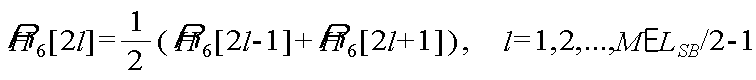
채널 품질 추정기(590)는 단블록(SB1, SB2)의 파일럿 신호로부터 채널 품질을 추정한다. 바람직하게는 채널 품질 추정기는 제2 단블록(SB2)의 파일럿 신호로부터 추정된 채널 H6[k]을 이용하여 채널 품질을 추정할 수 있다. 채널 품질 추정기(590)는 각 부반송파 위치에서 추정된 채널 H6[k]에 대하여 다음 수학식 10과 같이 선형 보간(linear interpolation)을 수행한다.The

![]()
![]()
위 선형보간된 방법이외의 다른 방법에 의한 보간법도 적용이 가능하다. 결국 전 주파수 대역의 부반송파에 대한 채널 품질을 추정한다.The interpolation method by a method other than the linear interpolation method is also applicable. As a result, the channel quality of the subcarriers of the entire frequency band is estimated.
도 10은 CDM 방식의 수신기를 나타낸 블록도이다.10 is a block diagram showing a CDM receiver.
도 10을 참조하면, 수신기(600)는 FFT부(640), 부반송파 디맵퍼(650), IDFT부(670), CIR 추정기(680) 및 채널 품질 추정기(695)를 포함한다.Referring to FIG. 10, the
안테나(610)에서 수신한 신호는 RF부(620)를 거쳐 디지털화된 신호가 된다. 디지털화된 신호는 CP 제거부(630)에 의해 CP가 제거된다. CP가 제거된 시간 영역 신호 ri[n]는 FFT부(640)에 의해 FFT를 수행하여 주파수 영역 신호 Yi'[k]로 변환된다. 여기서, FFT의 크기는 단블록(SB1, SB2)의 경우 NSB라 하고, 장블록(LB)의 경우 NLB라 한다. 변환된 신호 Yi'[k]는 부반송파 디맵퍼(650)에 의해 부반송파 할당 방식의 반대 과정을 통해 신호 Yi[k]가 된다. The signal received by the
CDM 방식은 시간 영역에서 채널 임펄스 응답(Channel Impulse Response; 이하 CIR)을 이용하여 채널 품질을 추정한다. CIR 추정기(680)는 시간 영역 파일럿 신호로부터 CIR hi[τ]를 추정한다. CIR은 다음 수학식 11과 같이 순환 상관(cyclic correlation) 연산을 이용하여 구한다.The CDM scheme estimates channel quality using a channel impulse response (CIR) in the time domain.

mod는 모듈로(modulo) 연산을 나타낸다. si는 송신기(100)에서의 시간 영역 파일럿 신호로, 수신기(600)에 미리 알려진 값이다.mod represents a modulo operation. s i is a time-domain pilot signal at the
윈도우부(685)는 CIR에 대해 다음 수학식 12와 같은 윈도우잉(windowing)을 행한다.The

즉, 윈도우부(685)는 CIR hi[τ]에서 소정 영역을 제외한 부분을 0으로 치환한다.That is, the
FFT부(690)는 윈도우잉된 CIR에 대해 FFT를 수행하여 주파수 영역 채널 ![]()
![]()
장블록(LB)의 데이터 신호를 위한 채널 추정은 다음 수학식 13과 같이 이루어질 수 있다.Channel estimation for the data signal of the long block LB may be performed as in Equation 13.

등화기(660)는 추정된 채널 ![]()
![]()

IDFT부(670)는 보상된 신호 Xi[k]에 대해 IDFT를 수행하여 시간 영역 신호 xi[n]로 변환한다. IDFT의 크기는 단블록(SB1, SB2)의 경우 LSB라 하고, 장블록(LB)의 경우 LLB라 한다. The
채널 품질 추정기(695)는 제2 단블록(SB2)의 파일럿 신호로부터 채널 품질을 추정한다. 각 부반송파 위치에서 추정된 채널 ![]()
![]()
FDM-L 방식의 경우 부반송파가 각 단말별로 국부적으로 밀집되어 있어 주파수 선택적 스케줄링을 위한 전 대역의 채널 품질을 추정하기 어렵다. FDM-D 방식의 경우 제1 단블록(SB1)과 제2 단블록(SB2)에서 단말별로 파일럿이 서로 엇갈리게 배 치되어 단말의 이동 속도가 큰 시간 선택적 채널 환경에서 채널 추정 오류가 커지고, 접속하는 단말의 수가 증가할수록 파일럿 간격이 넓어져 채널 품질 추정의 열화가 발생할 수 있다. CDM 방식의 경우 단말의 수가 증가할수록 윈도우잉 구간이 감소하여 다중 경로로 인한 지연 확산(delay spread)보다 윈도우잉 구간이 작아질 경우 정확한 CIR 추정이 어려워 채널 추정 및 채널 품질 추정의 열화가 발생할 수 있다.In the case of the FDM-L method, since subcarriers are locally concentrated for each terminal, it is difficult to estimate the channel quality of the entire band for frequency selective scheduling. In the case of the FDM-D scheme, pilots are alternately arranged for each UE in the first short block SB1 and the second short block SB2, so that the channel estimation error increases in a time-selective channel environment in which the mobile speed is large. As the number of terminals increases, the pilot interval may widen, which may cause deterioration of channel quality estimation. In the case of the CDM scheme, as the number of terminals increases, the windowing interval decreases, and thus, when the windowing interval is smaller than the delay spread due to the multipath, accurate CIR estimation may be difficult, resulting in degradation of channel estimation and channel quality estimation. .
도 11은 본 발명의 일 실시예에 따른 데이터 전송 방법을 나타낸 예시도이다.11 is an exemplary view showing a data transmission method according to an embodiment of the present invention.
도 11을 참조하면, 장블록(LB)에는 부반송파가 각 단말마다 국부적으로 밀집되어 할당된다. 즉 장블록(LB)에는 단말마다 연속적인 주파수 대역을 할당한다. Referring to FIG. 11, subcarriers are locally allocated to each UE in the long block LB. That is, the long block LB is allocated a continuous frequency band for each terminal.
단블록(SB1, SB2)의 부반송파에는 파일럿이 실린다. 제1 단블록(SB1)에는 동일한 장블록(LB)과 동일한 대역의 부반송파가 할당될 수 있다. 즉, 장블록(LB)과 제1 단블록(SB1)에는 FDM-L 방식과 동일하게 부반송파가 할당된다.The pilot is carried on the subcarriers of the short blocks SB1 and SB2. The first short block SB1 may be allocated subcarriers of the same long block LB and the same band. That is, subcarriers are allocated to the long block LB and the first short block SB1 in the same manner as the FDM-L scheme.
제2 단블록(SB2)에는 FDM-L 방식과 CDM 방식이 엇갈려서 할당된다. 즉 제2 단블록(SB2)에는 주파수 영역 직교성을 갖는 부반송파와 코드 영역 직교성을 갖는 부반송파가 번갈아가며 할당된다. 코드 영역에서의 직교성은 순환 변환 형태의 CAZAC 시퀀스 또는 블록 시퀀스를 이용하여 이룰 수 있다. 제2 단블록(SB2)에는 해당하는 단말의 장블록(LB)의 부반송파에 할당되는 대역과 동일한 대역을 갖는 부반송파와 서로 다른 단말 간에 겹쳐서 할당되는 부반송파가 엇갈려서 할당된다. The FDM-L scheme and the CDM scheme are alternately allocated to the second short block SB2. That is, the second short block SB2 is alternately allocated a subcarrier having frequency domain orthogonality and a subcarrier having code domain orthogonality. Orthogonality in the code domain may be achieved using a CAZAC sequence or a block sequence in the form of a cyclic transform. In the second short block SB2, subcarriers having the same band as the band allocated to the subcarrier of the long block LB of the corresponding UE and subcarriers allocated overlapping with each other are alternately allocated.
제2 단블록(SB2)에는 채널 추정을 위한 DM 파일럿(제1 파일럿)과 전 대역 채 널 품질 측정을 위한 CQ 파일럿(제2 파일럿)이 번갈아 가며 할당된다. DM 파일럿은 채널 추정을 위한 용도로 이용되고, CQ 파일럿은 채널 품질 측정을 위한 용도로 이용된다. DM 파일럿은 단말별로 서로 다른 주파수 대역에 할당되며, 주파수 영역에서 직교성을 가진다. CQ 파일럿은 단말별로 서로 겹치는 주파수 대역에 할당되며, 코드 영역에서 직교성을 가진다. DM 파일럿을 통한 채널 추정은 FFT를 통과하여 주파수 영역 채널 값을 얻은 후 이루어진다. CQ 파일럿을 통한 채널 품질 측정은 시간 영역에서 CIR 추정이 선행된 이후 FFT를 통과하여 주파수 영역 채널 값을 얻은 후 이루어진다. The second short block SB2 is alternately allocated a DM pilot (first pilot) for channel estimation and a CQ pilot (second pilot) for measuring a full band channel quality. The DM pilot is used for channel estimation and the CQ pilot is used for channel quality measurement. The DM pilot is allocated to different frequency bands for each terminal and has orthogonality in the frequency domain. The CQ pilots are allocated to frequency bands overlapping each other for each UE and have orthogonality in the code domain. Channel estimation through the DM pilot is made after passing the FFT to obtain the frequency domain channel value. The channel quality measurement through the CQ pilot is made after passing the FFT to obtain the frequency domain channel value after the CIR estimation is performed in the time domain.
본 발명에 의하면 제1 단블록(SB1)에 포함되는 파일럿에는 장블록(LB)의 대역과 같은 부반송파가 할당되지만, 제2 단블록(SB2)에 포함되는 파일럿에는 주파수 영역에서 직교성을 갖는 부반송파와 코드 영역에서 직교성을 갖는 부반송파가 번갈아 가며 할당한다. 따라서 채널 추정과 채널 품질 측정을 동시에 할 수 있어 고속 환경에서의 스케줄링에 유리하다.According to the present invention, a subcarrier, such as a band of the long block LB, is allocated to a pilot included in the first short block SB1, but a subcarrier having orthogonality in the frequency domain is assigned to a pilot included in the second short block SB2. Subcarriers with orthogonality are alternately allocated in the code domain. Therefore, channel estimation and channel quality measurement can be performed at the same time, which is advantageous for scheduling in a high speed environment.
서브 프레임의 구조상 제1 단블록(SB1)은 제2 단블록(SB2)보다 시간적으로 앞서 송신된다. 데이터는 장블록(LB)에 실리고, 데이터 중 제어 신호는 일반적으로 시간적으로 앞선 장블록(LB)에 실린다. 즉 제어 신호는 제2 단블록(SB2)보다 제1 단블록(SB1)에 가까운 장블록(LB)에 실린다. 제1 단블록(SB1)에는 채널 추정을 위한 파일럿만이 송신되므로, 제어 신호를 복조 및 디코딩하는데 있어서는 제1 단블록(SB1)의 파일럿을 이용함으로써 거의 FDM-L에 상당하는 성능을 얻을 수 있다. 따라서 채널 품질 측정을 위한 CQ 파일럿을 보다 시간적으로 후반부에 배치함으로써 CQ 파일럿의 추가로 인한 채널 추정의 열화를 효율적으로 줄일 수 있다.In the structure of the subframe, the first short block SB1 is transmitted in time ahead of the second short block SB2. Data is loaded in the long block LB, and control signals of the data are generally loaded in the long block LB. That is, the control signal is carried in the long block LB closer to the first short block SB1 than the second short block SB2. Since only the pilot for channel estimation is transmitted to the first short block SB1, the pilot of the first short block SB1 can be used to demodulate and decode the control signal, thereby achieving nearly FDM-L performance. . Therefore, by arranging the CQ pilot for channel quality measurement later in time, the degradation of the channel estimation due to the addition of the CQ pilot can be effectively reduced.
도 12는 본 발명의 일 실시예에 따른 수신기를 나타낸 블록도이다.12 is a block diagram illustrating a receiver according to an embodiment of the present invention.
도 12를 참조하면, 수신기(700)는 FFT부(740), 부반송파 디맵퍼(750), 채널 추정기(755), IDFT부(765) 및 채널 품질 추정기(790)를 포함한다.Referring to FIG. 12, the
안테나(710)에서 수신한 신호는 RF부(720)를 거쳐 디지털화된 신호가 된다. 디지털화된 신호는 CP 제거부(730)에 의해 CP가 제거된다. CP가 제거된 시간 영역 신호 ri[n]는 FFT부(740)에 의해 FFT를 수행하여 주파수 영역 신호 Yi'[k]로 변환된다. 여기서, FFT의 크기는 단블록(SB1, SB2)의 경우 NSB라 하고, 장블록(LB)의 경우 NLB라 한다. 단블록(SB1, SB2)의 시간 간격이 장블록(LB)의 시간 간격의 0.5배인 경우 NLB = 2NSB인 관계가 된다. 변환된 신호 Yi'[k]는 부반송파 디맵퍼(750)에 의해 부반송파 할당 방식의 반대 과정을 통해 신호 Yi[k]가 된다. The signal received by the
채널 추정기(755)는 제1 단블록(SB1)의 파일럿과 제2 단블록(SB2)의 DM 파일럿 신호로부터 채널 Hi[k]을 다음 수학식 15 내지 17과 같이 추정한다. The


등화기(760)는 추정된 채널 Hi[k]을 이용하여 장블록(LB)에 포함된 데이터 신호를 다음 수학식 18과 같이 보상한다.The

( )*는 켤례(conjugate)를 말하고, SNR은 채널을 통과한 수신된 신호대잡음비(Signal-to-Noise Ratio)이다. IDFT부(765)는 보상된 신호 Xi[k]에 대해 IDFT를 수행하여 시간 영역 신호 xi[n]로 변환한다. () * Is the conjugate and SNR is the received signal-to-noise ratio that passed through the channel. The
한편, 제2 단블록(SB2) 신호가 수신된 경우 주파수 영역에서 분리된 CQ 파일럿 Y6[k]에 대하여 IDFT부(770)를 통과시켜 시간 영역 신호 y6[n]으로 변환한다. CIR 추정기(775)는 시간 영역 신호 y6[n]에 대하여 다음 수학식 19와 같이 순환 상 관 연산을 통해 CIR을 추정한다.On the other hand, when the second short block (SB2) signal is received, the

여기서, s[n]은 송신기(100)의 시간 영역 CQ 파일럿 신호로 수신기(700)에 미리 알려진 값이다. mod는 모듈로(modulo) 연산을 나타낸다. Here, s [n] is a value previously known to the
윈도우부(780)는 CIR에 대해 다음 수학식 20과 같은 윈도우잉을 행한다.The

즉, 윈도우부(780)는 CIR h6[τ]에서 소정 영역을 제외한 부분을 0으로 치환한다. DFT부(785)는 윈도우잉된 CIR에 대해 FFT를 수행하여 주파수 영역 채널 ![]()
![]()
채널 품질 추정기(790)는 전체 주파수 대역에 관한 채널 값을 다음 수학식 21과 같이 구할 수 있다.The
각 부반송파 위치에서 추정된 채널값 ![]()
![]()
수신기(700)는 제안된 방식뿐만 아니라 CDM 방식에도 그대로 적용할 수 있다. 일반적인 SC-FDMA 시스템에서는 전송 가능한 전체 주파수 대역 중 양단의 주파수 대역에 보호 대역을 설정하고 있다. 이 보호 대역의 설정으로 인해 CDM 방식에서 단블록(SB1, SB2)의 부반송파 신호를 형성하는 CAZAC 시퀀스의 길이 LSB는 이용 가능한 전체 NSB 크기 보다 작은 값으로 설정된다. 따라서 CDM 방식에서도 제안된 수신기(700)를 적용할 수 있으며, 그 과정은 다음과 같다. FFT부(740)와 부반송파 디맵퍼(750)를 거친 파일럿 신호를 IDFT부(770)에 의해 LSB 크기의 IDFT을 수행한다. 이어서 CIR 추정기(775)와 윈도우부(780)를 거치고, DFT부(785)에 의해 LSB 크기의 DFT를 수행한다. CDM 방식에서는 DFT를 통과한 주파수 영역의 채널 추정 값을 채널의 품질 측정 및 등화 과정 모두에 이용할 수 있다.The
도 13은 채널 추정 성능을 비교한 그래프이다. 이는 단말의 이동 속도에 따른 BER(bit error rate)을 나타낸다. 모의 실험은 랜덤하게 변하는 무선 채널과 AWGN(Additive White Gaussian Noise) 환경에서 충분히 많은 반복 과정을 거쳐 통계적인 성능 수치를 기록함으로써 수행하였다. 무선 채널 모델은 COST 207 TU(Typical Urban)을 기반으로 하였으며, 이 모델은 실제 도심지 환경에서 무선 채널 상황을 수학적으로 표현한 것이다. 각 성능 평가는 채널 추정 성능 및 채널의 품질 측정 성능만을 알아보기 위한 것이므로 수신기의 동기는 완벽하게 이루어진 것으로 가정하였다.13 is a graph comparing channel estimation performance. This indicates a BER (bit error rate) according to the moving speed of the terminal. The simulation was performed by recording statistical performance figures through a sufficient number of iterations in randomly changing wireless channels and AWGN (Additive White Gaussian Noise) environments. The radio channel model is based on the COST 207 TU (Typical Urban), which is a mathematical representation of the radio channel situation in a real urban environment. Since each performance evaluation is only for channel estimation performance and quality measurement performance of the channel, the synchronization of the receiver is assumed to be perfect.
도 13을 참조하면, 본 발명에 의한 신호 구조는 기본적으로 FDM-L 방식을 기반으로 하며, 채널 추정을 한 파일럿의 일부를 채널의 품질 측정 용도로 사용하였기 때문에 결과에서 볼 수 있듯이 기존 FDM-L 방식에 비하여 BER 성능이 약간 열화된 것을 확인할 수 있다. 그러나 제안된 방식은 FDM-D, CDM 방식보다 더 낮은 비트 에러 성능을 나타내며, 전체적으로 볼 때 이동체 속도에 따른 성능 열화가 비교적 크지 않음을 알 수 있다.Referring to FIG. 13, the signal structure according to the present invention is basically based on the FDM-L scheme, and since a part of the channel estimation pilot is used for measuring the quality of the channel, as shown in the result, the existing FDM-L It can be seen that the BER performance is slightly degraded compared to the method. However, the proposed scheme shows lower bit error performance than the FDM-D and CDM schemes, and as a whole, it can be seen that the performance degradation due to the moving speed is relatively large.
도 14는 전 주파수 대역에 대한 채널 품질 성능을 비교한 그래프이다. 각 신호 구조의 채널 품질 측정 성능을 비교하기 위해 Eb/No에 따른 MSE(Mean Square Error) 성능을 나타낸다. FDM-L 방식은 앞서 언급하였듯이 전체 주파수 대역에 대한 채널 품질 측정이 불가능한 구조이므로 이 실험 결과에서는 제외되었다. 14 is a graph comparing channel quality performance for all frequency bands. Mean square error (MSE) performance according to Eb / No is shown to compare the channel quality measurement performance of each signal structure. As mentioned above, the FDM-L method is excluded from this experiment because it is impossible to measure the channel quality over the entire frequency band.
도 14를 참조하면, 본 발명에 의한 신호 구조가 FDM-D나 CDM에 비해 보다 낮은 MSE 성능 즉, 가장 작은 오차율을 나타낸다. 따라서 채널의 품질 측정 성능이 개선된 것을 알 수 있다.Referring to FIG. 14, the signal structure according to the present invention exhibits lower MSE performance, that is, the smallest error rate, compared to FDM-D or CDM. Therefore, it can be seen that the quality measurement performance of the channel is improved.
제안된 신호 구조는 FDM-L 방식과는 달리 데이터 복조를 위한 채널 추정과 전체 주파수 대역에 대한 채널의 품질 측정을 동시에 수행할 수 있는 구조이며, FDM-D 방식과 CDM 방식에 비해 보다 더 우수한 채널 추정 성능 및 채널의 품질 측정 성능을 발휘한다. Unlike the FDM-L method, the proposed signal structure is capable of simultaneously performing channel estimation for data demodulation and channel quality measurement for the entire frequency band, and is superior to the FDM-D and CDM methods. Demonstrate performance of estimation performance and quality measurement of channels.
도 15는 본 발명의 다른 실시예에 따른 데이터 전송 방법을 나타낸 예시도이다.15 is an exemplary view showing a data transmission method according to another embodiment of the present invention.
도 15를 참조하면, 장블록(LB)에는 부반송파가 각 단말마다 국부적으로 밀집 되어 할당된다. 장블록(LB)에는 단말마다 연속적인 주파수 대역을 할당한다. Referring to FIG. 15, subcarriers are locally allocated to each terminal in the long block LB. The long block LB is allocated with a continuous frequency band for each terminal.
단블록(SB1, SB2)의 부반송파에는 파일럿이 실린다. 제1 단블록(SB1)의 부반송파에는 동일한 단말끼리는 서로 인접하지 않게 일정 간격으로 분산되어 할당된다. 각 단말별로 부반송파가 밀집되지 않고 일정 간격으로 분산되도록 한다. 즉, 제1 단블록(SB1)에는 FDM-D 방식과 동일하게 부반송파가 할당된다.The pilot is carried on the subcarriers of the short blocks SB1 and SB2. Subcarriers of the first short block SB1 are allocated with the same terminals distributed at regular intervals without being adjacent to each other. The subcarriers are distributed to each terminal at regular intervals without being crowded. That is, subcarriers are allocated to the first short block SB1 in the same manner as in the FDM-D scheme.
제2 단블록(SB2)에는 FDM-L 방식과 CDM 방식이 엇갈려서 할당된다. 즉 제2 단블록(SB2)에는 주파수 영역 직교성을 갖는 부반송파와 코드 영역 직교성을 갖는 부반송파가 번갈아가며 할당된다. 즉, 제2 단블록(SB2)의 파일럿 신호에는 해당하는 단말의 장블록(LB)의 부반송파에 할당되는 대역과 동일한 대역을 갖는 부반송파와 서로 다른 단말간에 겹쳐서 할당되는 부반송파가 엇갈려서 할당된다. The FDM-L scheme and the CDM scheme are alternately allocated to the second short block SB2. That is, the second short block SB2 is alternately allocated a subcarrier having frequency domain orthogonality and a subcarrier having code domain orthogonality. That is, the subcarriers having the same band as the band allocated to the subcarrier of the long block LB of the corresponding UE and the subcarriers overlapped with the other terminals are alternately allocated to the pilot signal of the second short block SB2.
채널 추정 및 채널 품질 측정은 제1 단블록(SB1)의 파일럿과 제2 단블록(SB2)의 파일럿 모두를 이용할 수 있다. 양자 모두 전체 주파수 대역에 걸쳐서 송신되기 때문이다.Channel estimation and channel quality measurement may use both the pilot of the first short block (SB1) and the pilot of the second short block (SB2). This is because both are transmitted over the entire frequency band.
도 16은 본 발명의 또 다른 실시예에 따른 데이터 전송 방법을 나타낸 예시도이다.16 is an exemplary view showing a data transmission method according to another embodiment of the present invention.
도 16을 참조하면, 장블록(LB)에는 부반송파가 각 단말마다 국부적으로 밀집되어 할당된다. Referring to FIG. 16, subcarriers are allocated to the long block LB in each terminal locally.
단블록(SB1, SB2)의 부반송파에는 파일럿이 실린다. 제1 단블록(SB1)에는 FDM-L 방식과 CDM 방식이 엇갈려서 할당된다. 즉 제1 단블록(SB1)에는 주파수 영역 직교성을 갖는 부반송파와 코드 영역 직교성을 갖는 부반송파가 번갈아가며 할당된 다. 해당하는 단말의 장블록(LB)의 부반송파에 할당되는 대역과 동일한 대역을 갖는 부반송파와 서로 다른 단말간에 겹쳐서 할당되는 부반송파가 엇갈려서 할당된다. 제1 단블록(SB1)에는 채널 추정을 위한 DM 파일럿(제1 파일럿)과 전 대역 채널 품질 측정을 위한 CQ 파일럿(제2 파일럿)이 번갈아 가며 할당된다. The pilot is carried on the subcarriers of the short blocks SB1 and SB2. The FDM-L scheme and the CDM scheme are alternately allocated to the first short block SB1. That is, subcarriers having frequency domain orthogonality and subcarriers having code domain orthogonality are alternately allocated to the first short block SB1. The subcarriers having the same band as the band allocated to the subcarrier of the long block LB of the corresponding terminal and the subcarriers allocated overlapping with each other are alternately allocated. The first short block SB1 is alternately allocated a DM pilot (first pilot) for channel estimation and a CQ pilot (second pilot) for measuring the full band channel quality.
제2 단블록(SB2)에는 동일한 장블록(LB)과 동일한 대역의 부반송파가 할당될 수 있다. 즉, 장블록(LB)과 제2 단블록(SB2)에는 FDM-L 방식과 동일하게 부반송파가 할당된다.The second short block SB2 may be allocated subcarriers of the same long block LB and the same band. That is, subcarriers are allocated to the long block LB and the second short block SB2 in the same manner as the FDM-L scheme.
채널 추정 및 채널 품질 측정은 제1 단블록(SB1)의 파일럿을 이용할 수 있고, 제2 단블록(SB2)의 파일럿은 채널 추정에 사용할 수 있다. Channel estimation and channel quality measurement may use the pilot of the first short block (SB1), the pilot of the second short block (SB2) can be used for channel estimation.
도 17은 본 발명의 또 다른 실시예에 따른 데이터 전송 방법을 나타낸 예시도이다.17 is an exemplary view showing a data transmission method according to another embodiment of the present invention.
도 17을 참조하면, 장블록(LB)에는 부반송파가 각 단말마다 국부적으로 밀집되어 할당된다. Referring to FIG. 17, subcarriers are locally allocated to each UE in the long block LB.
단블록(SB1, SB2)의 부반송파에는 파일럿이 실린다. 단블록(SB1, SB2)에는 주파수 영역 직교성을 갖는 부반송파와 코드 영역 직교성을 갖는 부반송파가 번갈아가며 할당된다. 해당하는 단말의 장블록(LB)의 부반송파에 할당되는 대역과 동일한 대역을 갖는 부반송파와 서로 다른 단말간에 겹쳐서 할당되는 부반송파가 엇갈려서 할당된다. 단블록(SB1, SB2)에는 채널 추정을 위한 DM 파일럿(제1 파일럿)과 전 대역 채널 품질 측정을 위한 CQ 파일럿(제2 파일럿)이 번갈아 가며 할당된다. The pilot is carried on the subcarriers of the short blocks SB1 and SB2. The short blocks SB1 and SB2 are alternately allocated subcarriers with frequency domain orthogonality and subcarriers with code domain orthogonality. The subcarriers having the same band as the band allocated to the subcarrier of the long block LB of the corresponding terminal and the subcarriers allocated overlapping with each other are alternately allocated. The short blocks SB1 and SB2 are alternately allocated a DM pilot (first pilot) for channel estimation and a CQ pilot (second pilot) for measuring the full band channel quality.
채널 추정 및 채널 품질 측정은 제1 단블록(SB1)의 파일럿과 제2 단블 록(SB2)의 파일럿 모두를 이용할 수 있다. 양자 모두 전체 주파수 대역에 걸쳐서 송신되기 때문이다.Channel estimation and channel quality measurement may use both the pilot of the first short block (SB1) and the pilot of the second short block (SB2). This is because both are transmitted over the entire frequency band.
도 18은 본 발명의 일 실시예에 따른 파일럿 할당 방법을 나타낸 예시도이다.18 is an exemplary view showing a pilot allocation method according to an embodiment of the present invention.
도 18을 참조하면, 파일럿은 주파수 영역 직교성을 갖는 부반송파와 코드 영역 직교성을 갖는 부반송파에 번갈아가며 할당된다. 따라서, 단말 사이의 직교성은 보장되고 채널 추정과 채널 품질 측정이 동시에 가능하다. Referring to FIG. 18, pilots are alternately allocated to subcarriers having frequency domain orthogonality and subcarriers having code domain orthogonality. Therefore, orthogonality between terminals is guaranteed and channel estimation and channel quality measurement are possible at the same time.
제1 파일럿은 단말별로 서로 겹치지 않는 부반송파에 실리고, 제2 파일럿은 단말별로 서로 겹치는 부반송파에 실린다. 제1 파일럿은 채널 추정을 위한 DM 파일럿이 되고, 제2 파일럿은 전 대역 채널 품질 측정을 위한 CQ 파일럿이 된다.The first pilot is carried on subcarriers that do not overlap each other for each terminal, and the second pilot is carried on subcarriers that overlap each other for each terminal. The first pilot becomes a DM pilot for channel estimation and the second pilot becomes a CQ pilot for full band channel quality measurement.
본 발명은 하드웨어, 소프트웨어 또는 이들의 조합으로 구현될 수 있다. 하드웨어 구현에 있어, 상술한 기능을 수행하기 위해 디자인된 ASIC(application specific integrated circuit), DSP(digital signal processing), PLD(programmable logic device), FPGA(field programmable gate array), 프로세서, 제어기, 마이크로 프로세서, 다른 전자 유닛 또는 이들의 조합으로 구현될 수 있다. 소프트웨어 구현에 있어, 상술한 기능을 수행하는 모듈로 구현될 수 있다. 소프트웨어는 메모리 유닛에 저장될 수 있고, 프로세서에 의해 실행된다. 메모리 유닛이나 프로세서는 당업자에게 잘 알려진 다양한 수단을 채용할 수 있다.The present invention may be implemented in hardware, software, or a combination thereof. (DSP), a programmable logic device (PLD), a field programmable gate array (FPGA), a processor, a controller, a microprocessor, and the like, which are designed to perform the above- , Other electronic units, or a combination thereof. In the software implementation, the module may be implemented as a module that performs the above-described function. The software may be stored in a memory unit and executed by a processor. The memory unit or processor may employ various means well known to those skilled in the art.
이상 본 발명에 대하여 실시예를 참조하여 설명하였지만, 해당 기술 분야의 통상의 지식을 가진 자는 본 발명의 기술적 사상 및 영역으로부터 벗어나지 않는 범위 내에서 본 발명을 다양하게 수정 및 변경시켜 실시할 수 있음을 이해할 수 있을 것이다. 따라서 상술한 실시예에 한정되지 않고, 본 발명은 이하의 특허청구범위의 범위 내의 모든 실시예들을 포함한다고 할 것이다.Although the present invention has been described above with reference to the embodiments, it will be apparent to those skilled in the art that the present invention may be modified and changed in various ways without departing from the spirit and scope of the present invention. I can understand. Therefore, the present invention is not limited to the above-described embodiment, and the present invention will include all embodiments within the scope of the following claims.
상기에서 상술한 바와 같이 본 발명에 의하면 데이터 복조를 위한 채널 추정과 전체 주파수 대역에 대한 채널의 품질 측정을 동시에 수행할 수 있으며, 단말의 이동 속도가 커지더라도 성능의 열화가 크게 발생하지 않는다. 따라서 고속 환경에서 스케줄링에 유리하다. As described above, according to the present invention, channel estimation for data demodulation and channel quality measurement for the entire frequency band can be simultaneously performed, and performance deterioration does not occur significantly even when the moving speed of the terminal increases. Therefore, scheduling is advantageous in a high speed environment.
Claims (13)
Priority Applications (1)
| Application Number | Priority Date | Filing Date | Title |
|---|---|---|---|
| KR1020060089838A KR101188544B1 (en) | 2006-09-15 | 2006-09-15 | Data Transmission Method for Single Carrier-Frequency Division Multiple Access System and Pilot Allocation Method |
Applications Claiming Priority (1)
| Application Number | Priority Date | Filing Date | Title |
|---|---|---|---|
| KR1020060089838A KR101188544B1 (en) | 2006-09-15 | 2006-09-15 | Data Transmission Method for Single Carrier-Frequency Division Multiple Access System and Pilot Allocation Method |
Publications (2)
| Publication Number | Publication Date |
|---|---|
| KR20080025260A KR20080025260A (en) | 2008-03-20 |
| KR101188544B1 true KR101188544B1 (en) | 2012-10-05 |
Family
ID=39413194
Family Applications (1)
| Application Number | Title | Priority Date | Filing Date |
|---|---|---|---|
| KR1020060089838A KR101188544B1 (en) | 2006-09-15 | 2006-09-15 | Data Transmission Method for Single Carrier-Frequency Division Multiple Access System and Pilot Allocation Method |
Country Status (1)
| Country | Link |
|---|---|
| KR (1) | KR101188544B1 (en) |
Families Citing this family (8)
| Publication number | Priority date | Publication date | Assignee | Title |
|---|---|---|---|---|
| KR100945827B1 (en) * | 2008-04-08 | 2010-03-05 | 주식회사 휴커넥스 | Point-to-multipoint network device using phone-line |
| KR101567078B1 (en) | 2008-06-26 | 2015-11-09 | 엘지전자 주식회사 | Apparatus and method for data transmission using multiple antenna |
| KR101534349B1 (en) | 2008-06-26 | 2015-07-10 | 엘지전자 주식회사 | Method for data transmission using space time block code |
| KR101467586B1 (en) | 2008-06-26 | 2014-12-02 | 엘지전자 주식회사 | Apparatus and method for data transmission using transmit diversity in wireless system |
| KR101497154B1 (en) | 2008-06-26 | 2015-03-02 | 엘지전자 주식회사 | Apparatus and method for data transmission using transmit diversity in sc-fdma system |
| KR101507170B1 (en) * | 2008-06-26 | 2015-03-31 | 엘지전자 주식회사 | Apparatus and method for data transmission using transmit diversity in sc-fdma system |
| KR101440628B1 (en) | 2008-08-11 | 2014-09-17 | 엘지전자 주식회사 | Apparatus and method for data transmission using transmit diversity in sc-fdma system |
| KR102571570B1 (en) * | 2022-12-05 | 2023-08-29 | 국방과학연구소 | Method and apparatus for transmitting and receiving a single carrier frequency domain equalizer signal in a single carrier based wireless communication system |
Citations (2)
| Publication number | Priority date | Publication date | Assignee | Title |
|---|---|---|---|---|
| WO2006020021A1 (en) | 2004-07-16 | 2006-02-23 | Qualcomm Incorporated | Incremental pilot insertion for channel and interference estimation |
| WO2006096784A1 (en) | 2005-03-07 | 2006-09-14 | Qualcomm Incorporated | Pilot transmission and channel estimation for a communication system utilizing frequency division multiplexing |
-
2006
- 2006-09-15 KR KR1020060089838A patent/KR101188544B1/en active IP Right Grant
Patent Citations (2)
| Publication number | Priority date | Publication date | Assignee | Title |
|---|---|---|---|---|
| WO2006020021A1 (en) | 2004-07-16 | 2006-02-23 | Qualcomm Incorporated | Incremental pilot insertion for channel and interference estimation |
| WO2006096784A1 (en) | 2005-03-07 | 2006-09-14 | Qualcomm Incorporated | Pilot transmission and channel estimation for a communication system utilizing frequency division multiplexing |
Also Published As
| Publication number | Publication date |
|---|---|
| KR20080025260A (en) | 2008-03-20 |
Similar Documents
| Publication | Publication Date | Title |
|---|---|---|
| KR100927919B1 (en) | Pilot assignment method | |
| US11343129B2 (en) | Method and system for providing code cover to OFDM symbols in multiple user system | |
| US7848438B2 (en) | Method and apparatus for pilot signal transmission | |
| JP4964239B2 (en) | Method and apparatus for transmitting a pilot signal | |
| KR100882755B1 (en) | Multicarrier modulation system with cyclic delay diversity | |
| EP1762019B1 (en) | Method and apparatus for accessing a wireless communication system | |
| TWI430605B (en) | Method and user equipment for transmitting pilot for multiple carrier system | |
| CN101563899B (en) | Uplink inter-carrier interference cancellation for OFDMA systems | |
| KR101188544B1 (en) | Data Transmission Method for Single Carrier-Frequency Division Multiple Access System and Pilot Allocation Method | |
| US20090168730A1 (en) | Pilot Signal Allocation Method and Apparatus | |
| EP1473862B1 (en) | Apparatus and method for transmitting training symbol groups in an OFDM communications system using multiple antennas | |
| WO2018100591A1 (en) | A method and a system for transmitting dft-s-ofdm symbols | |
| US20110096867A1 (en) | Method and Apparatus for Providing Pilot Signals in OFDM Frames | |
| JP2008160842A (en) | Communications system | |
| JPWO2007088580A1 (en) | Communication control method, receiving station apparatus, transmitting station apparatus, and communication system | |
| KR20160088792A (en) | Communication method and apparatus based on a filter bank multi-carrier modulation | |
| KR101207677B1 (en) | Data Transmission Method and Pilot Allocation Method | |
| JP3891986B2 (en) | Multi-carrier transmission method and apparatus | |
| KR20090093025A (en) | Pilot allocation method for channel quality estimation in sc-fdma system and ofdma system, and a transmitter and a receiver for channel quality estimation using the method | |
| KR101040465B1 (en) | Method for channel estimation in a cazac code based mobile system |
Legal Events
| Date | Code | Title | Description |
|---|---|---|---|
| A201 | Request for examination | ||
| E701 | Decision to grant or registration of patent right | ||
| GRNT | Written decision to grant | ||
| FPAY | Annual fee payment |
Payment date: 20150824 Year of fee payment: 4 |
|
| FPAY | Annual fee payment |
Payment date: 20160824 Year of fee payment: 5 |
|
| FPAY | Annual fee payment |
Payment date: 20170814 Year of fee payment: 6 |
|
| FPAY | Annual fee payment |
Payment date: 20180814 Year of fee payment: 7 |