EP2960422A1 - Verbesserte jalousien mit nur einer zugschnur - Google Patents
Verbesserte jalousien mit nur einer zugschnur Download PDFInfo
- Publication number
- EP2960422A1 EP2960422A1 EP13863319.3A EP13863319A EP2960422A1 EP 2960422 A1 EP2960422 A1 EP 2960422A1 EP 13863319 A EP13863319 A EP 13863319A EP 2960422 A1 EP2960422 A1 EP 2960422A1
- Authority
- EP
- European Patent Office
- Prior art keywords
- rotary
- spring
- cord
- stopper
- fixing
- Prior art date
- Legal status (The legal status is an assumption and is not a legal conclusion. Google has not performed a legal analysis and makes no representation as to the accuracy of the status listed.)
- Granted
Links
Images



Classifications
-
- E—FIXED CONSTRUCTIONS
- E06—DOORS, WINDOWS, SHUTTERS, OR ROLLER BLINDS IN GENERAL; LADDERS
- E06B—FIXED OR MOVABLE CLOSURES FOR OPENINGS IN BUILDINGS, VEHICLES, FENCES OR LIKE ENCLOSURES IN GENERAL, e.g. DOORS, WINDOWS, BLINDS, GATES
- E06B9/00—Screening or protective devices for wall or similar openings, with or without operating or securing mechanisms; Closures of similar construction
- E06B9/24—Screens or other constructions affording protection against light, especially against sunshine; Similar screens for privacy or appearance; Slat blinds
- E06B9/26—Lamellar or like blinds, e.g. venetian blinds
- E06B9/28—Lamellar or like blinds, e.g. venetian blinds with horizontal lamellae, e.g. non-liftable
- E06B9/30—Lamellar or like blinds, e.g. venetian blinds with horizontal lamellae, e.g. non-liftable liftable
- E06B9/32—Operating, guiding, or securing devices therefor
- E06B9/322—Details of operating devices, e.g. pulleys, brakes, spring drums, drives
-
- E—FIXED CONSTRUCTIONS
- E06—DOORS, WINDOWS, SHUTTERS, OR ROLLER BLINDS IN GENERAL; LADDERS
- E06B—FIXED OR MOVABLE CLOSURES FOR OPENINGS IN BUILDINGS, VEHICLES, FENCES OR LIKE ENCLOSURES IN GENERAL, e.g. DOORS, WINDOWS, BLINDS, GATES
- E06B9/00—Screening or protective devices for wall or similar openings, with or without operating or securing mechanisms; Closures of similar construction
- E06B9/24—Screens or other constructions affording protection against light, especially against sunshine; Similar screens for privacy or appearance; Slat blinds
- E06B9/40—Roller blinds
- E06B9/42—Parts or details of roller blinds, e.g. suspension devices, blind boxes
-
- E—FIXED CONSTRUCTIONS
- E06—DOORS, WINDOWS, SHUTTERS, OR ROLLER BLINDS IN GENERAL; LADDERS
- E06B—FIXED OR MOVABLE CLOSURES FOR OPENINGS IN BUILDINGS, VEHICLES, FENCES OR LIKE ENCLOSURES IN GENERAL, e.g. DOORS, WINDOWS, BLINDS, GATES
- E06B9/00—Screening or protective devices for wall or similar openings, with or without operating or securing mechanisms; Closures of similar construction
- E06B9/56—Operating, guiding or securing devices or arrangements for roll-type closures; Spring drums; Tape drums; Counterweighting arrangements therefor
- E06B9/78—Operating, guiding or securing devices or arrangements for roll-type closures; Spring drums; Tape drums; Counterweighting arrangements therefor for direct manual operation, e.g. by tassels, by handles
-
- E—FIXED CONSTRUCTIONS
- E06—DOORS, WINDOWS, SHUTTERS, OR ROLLER BLINDS IN GENERAL; LADDERS
- E06B—FIXED OR MOVABLE CLOSURES FOR OPENINGS IN BUILDINGS, VEHICLES, FENCES OR LIKE ENCLOSURES IN GENERAL, e.g. DOORS, WINDOWS, BLINDS, GATES
- E06B9/00—Screening or protective devices for wall or similar openings, with or without operating or securing mechanisms; Closures of similar construction
- E06B9/56—Operating, guiding or securing devices or arrangements for roll-type closures; Spring drums; Tape drums; Counterweighting arrangements therefor
- E06B9/80—Safety measures against dropping or unauthorised opening; Braking or immobilising devices; Devices for limiting unrolling
- E06B9/82—Safety measures against dropping or unauthorised opening; Braking or immobilising devices; Devices for limiting unrolling automatic
- E06B9/90—Safety measures against dropping or unauthorised opening; Braking or immobilising devices; Devices for limiting unrolling automatic for immobilising the closure member in various chosen positions
-
- E—FIXED CONSTRUCTIONS
- E06—DOORS, WINDOWS, SHUTTERS, OR ROLLER BLINDS IN GENERAL; LADDERS
- E06B—FIXED OR MOVABLE CLOSURES FOR OPENINGS IN BUILDINGS, VEHICLES, FENCES OR LIKE ENCLOSURES IN GENERAL, e.g. DOORS, WINDOWS, BLINDS, GATES
- E06B9/00—Screening or protective devices for wall or similar openings, with or without operating or securing mechanisms; Closures of similar construction
- E06B9/56—Operating, guiding or securing devices or arrangements for roll-type closures; Spring drums; Tape drums; Counterweighting arrangements therefor
- E06B9/78—Operating, guiding or securing devices or arrangements for roll-type closures; Spring drums; Tape drums; Counterweighting arrangements therefor for direct manual operation, e.g. by tassels, by handles
- E06B2009/785—Operating, guiding or securing devices or arrangements for roll-type closures; Spring drums; Tape drums; Counterweighting arrangements therefor for direct manual operation, e.g. by tassels, by handles by belts, straps, bands, tapes, cords, tassels
-
- E—FIXED CONSTRUCTIONS
- E06—DOORS, WINDOWS, SHUTTERS, OR ROLLER BLINDS IN GENERAL; LADDERS
- E06B—FIXED OR MOVABLE CLOSURES FOR OPENINGS IN BUILDINGS, VEHICLES, FENCES OR LIKE ENCLOSURES IN GENERAL, e.g. DOORS, WINDOWS, BLINDS, GATES
- E06B9/00—Screening or protective devices for wall or similar openings, with or without operating or securing mechanisms; Closures of similar construction
- E06B9/56—Operating, guiding or securing devices or arrangements for roll-type closures; Spring drums; Tape drums; Counterweighting arrangements therefor
- E06B9/80—Safety measures against dropping or unauthorised opening; Braking or immobilising devices; Devices for limiting unrolling
- E06B9/82—Safety measures against dropping or unauthorised opening; Braking or immobilising devices; Devices for limiting unrolling automatic
- E06B9/90—Safety measures against dropping or unauthorised opening; Braking or immobilising devices; Devices for limiting unrolling automatic for immobilising the closure member in various chosen positions
- E06B2009/905—Safety measures against dropping or unauthorised opening; Braking or immobilising devices; Devices for limiting unrolling automatic for immobilising the closure member in various chosen positions using wrap spring clutches
Definitions
- the present invention relates, in general, to an improved single-cord type blind and, more particularly, to an improved single-cord type blind which has less parts than in a conventional product and in which a stopper and a rotor are compressed and released with friction force of a spring so that a screen can be safely and accurately raised and lowered.
- a roller blind is used, instead of a curtain, in an office, home, a restaurant, etc.
- the roller blind blocks light incident through a window or the like with the action of drawing, in one direction, a ball chain engaged with a sprocket, which is mounted on one side of a bracket, so that a screen is unwound and lowered from a rotary shaft with a spring force of a spring and then is fixed at a certain position.
- a conventional roll blind 10 is configured such that a rotary member 5 and a speed-reduction member 8 are respectively mounted on both brackets 9, and a winding shaft on which the screen is wound is mounted to surround the members.
- the rotary member 5 is configured such that a connecting shaft 3 having a rotary ring 2 is connected to a rotary body 1, and a spring 4 is fixedly mounted between the rotary body 1 and the rotary ring 2 to surround the connecting shaft 3 so that the rotary body 2 laterally moves the connecting shaft 3 with spring force of the spring 4.
- the speed-reduction member 8 is configured such that a reducer 6 is mounted at the front of another rotary body 1 having an adjuster and a stationary shaft 7 having a reduction nut 7a is coupled to the reducer.
- a rotary shaft on which a screen is wound is coupled to the outside of both the rotary bodies 1, and the brackets 9 are fastened to a window frame or a wall around a window using screws or the like.
- the screen is raised or lowered by drawing a ball chain cord which is engaged around and hangs down in two strings from a sprocket. Specifically, when one string of the ball chain cord is drawn, the screen is lowered to block light, and when the other string of the ball chain cord is drawn, the screen is raised to make the window clear.
- the single-cord type blind includes a fixing body 10, a gear unit 50, an operating plate 60, a blocking plate 70, a transfer member 80, and a cover 90.
- the fixing body 10 includes a fixing plate 15, which is provided on one side with a central raised fixing section 12 having a fixing groove 11 into which a coiled spring 19 is coupled.
- the raised section has a fixing shaft 13 protruding from the center thereof and a plurality of fixing protrusions 14 around the fixing shaft.
- the gear unit 50 includes a central gear 20, which is mounted around the outer surface of the fixing shaft 13 and has symmetrically-arranged reinforcing steps 21 on an inner surface thereof and an outer threaded part 22, circumferential small-gears 30, which are coupled to the fixing protrusions 14 and each have threaded parts 31 in such a way as to be engaged with the central gear 20, and a fixing ring 40 which is connected with the central gear and has symmetrically-arranged outer fixing steps 42 each having a cut groove 41 into which an engaging step 45 of a spring 44 is fastened.
- the operating plate 60 includes a rotary gear 65 which has internal and external threads 64 and is coupled in a coupling groove at the front of the operating plate in such a manner as to internally engage with the circumferential small-gears 30, wherein a rotary cord 62 having a grip 61 on its lower portion is wound around an outer circumference thereof.
- the blocking plate 70 has a central through opening 71 and is fixedly mounted at the front of the operating plate 60 so as to prevent the gear unit 50 and the rotary cord 62 from being getting out of their positions.
- the transfer member 80 is mounted through the through opening 71 of the blocking plate 70 such that it abuts against the reinforcing steps 21 of the central gear 20, and has a central opening 81, into which the fixing shaft 13 is inserted, and has a front threaded end 84 and a rear coupling groove 83 having opposite side walls, one of which has an inclined surface 82.
- the cover 90 is provided, in one side thereof, with a rotary part 93 which has a central opening 92 and a threaded end 91 to be engaged and coupled with the front threaded end 84 of the transfer member 80.
- the present invention has been made keeping in mind the above problems occurring in the related art, and the present invention is intended to propose a single-cord type blind in which the operation of a screen is performed by compression and release between a stopper and a rotary part using a spring force of a spring, instead of a conventional gear mechanism, thereby facilitating an accurate operation of the screen irrespective of different users.
- a single-cord type blind including: a stationary body, in which a fixing plate having a fixing shaft is disposed at the front side thereof and a torsion spring is mounted, wherein the stationary body has a rotary plate having a rotary cylinder with engaging parts and coupling grooves formed on an inner surface and a distal end thereof, respectively, the fixing shaft being provided on an outer surface thereof with a washer groove and being fixedly mounted in the rotary cylinder; a gear unit having a plurality of gears, an operating plate having a gripped operating cord and configured to rotate in cooperation with the plurality of gears; a blocking plate preventing the gear unit and the operating cord from getting out of their positions; and a transfer member screw-coupled with a rotary part of a cover so as to couple and decouple the cover, the single-cord type blind further including:
- the present invention has following effects.
- the number of parts is reduced so as to simplify the structure, thereby providing the effect of reducing the manufacturing cost and improving price competitiveness.
- a stopper and a rotary part are compressed against and released from each other by means of friction force of a spring, thereby providing the effect of a screen being safely operated.
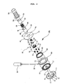
- FIG. 3 is an exploded perspective view of the entire construction of a single-cord type blind according to an embodiment of the present invention
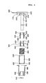
- FIG. 4 is a sectional view showing the entire construction of the single-cord type blind of the present invention
- FIG. 5 is a sectional view showing the entire construction of the assembled blind of the present invention
- FIG. 6 is a perspective view showing an assembled state of a spring
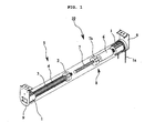
- FIG. 7 is a perspective view showing an assembled state of the blind
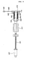
- FIG. 9 is a sectional view showing the operation of the blind of the present invention.
- Reference numeral 200 denotes a main body of the single-cord type blind according to the present invention.
- the main body 200 includes a stationary body 210 which has a rotary cylinder 212 having engaging parts 213 therein, a stopper 220 which is fastened to the engaging parts of the stationary body 210 and which has a front coupling part 221 and a rear fixing part 223, a rotary section 230 which has front coupling grooves 231 and a pair of symmetrically-arranged fastening protrusions 234 each having an upper flange 232, a spring 240 which is mounted around the coupling part 221 of the stopper 220, a protective tube 250 which has a hollow cylindrical body having a front opening 251 and rear-side multiple coupling pins 253, wherein the cylindrical body is provided, on a front end thereof, with an inner fixing ring 252 against which the spring 240 is seated, a rotary tube 260 which is coupled around the protective tube 250 and which is provided therein with a plurality of inner protrusions 261 to be coupled into the coupling grooves 231 of the rotary section 230, and a
- the stationary body 210 has a rotary plate 211 which is rotated in a disc-type casing by means of elastic force of a torsion spring.
- the rotary plate 211 has the rotary cylinder 212 which is provided on its inner surface and upper end with the engaging parts 213 and coupling grooves 214, respectively.
- a length of the fixing shaft 215 is fixedly mounted into the rotary cylinder at one end thereof, and has the washer groove 216 on a front-side outer surface thereof.
- An operating cord 280 that connects in a single line is connected with the torsion spring which is connected with the rotary plate 211 disposed in the stationary body 210 such that the torsion spring is operated by externally drawing the operating cord 280.
- the operating cord 280 is provided on a distal end thereof with a loop-type grip 281 to facilitate a vertical motion of the operating cord.
- the stopper 220 has a through-hole 225, the front coupling part 221 having an engaging flange 222, and the rear fixing part 224 having a plurality of grooves 223 on an end thereof.
- the stopper 220 is inserted around the fixing shaft through the through-hole 225 such that the grooves 223 of the fixing part 224 are meshed with the engaging parts 213 of the rotary cylinder 212 so that the stopper 220 and the rotary plate 211 can rotate together.
- the stopper 220 may be formed of a metal material to enhance friction force with respect to the spring 240.
- the rotary section 230 has front coupling grooves 231 and the pair of symmetrically-arranged fastening protrusions 234 each having an upper flange 232 with cut grooves 233 formed on opposite sides thereof.
- the rotary section also has a through-hole 235 through which the rotary section is inserted around the fixing shaft 215.
- the fastening protrusions 234 of the rotary section 230 are elastically flexible toward each other by means of the cut grooves 233.
- the rotary section 230 is coupled with the stopper 220 so as to act as a single-piece unit.
- the assembly is carried out by insertion of fastening protrusions 234 of the rotary section 230 into the through-hole 225 of the stopper 220.
- the rotary section 230 can freely rotate in the through-hole 225 of the stopper 220.
- the coupling part 21 has a diameter that is larger than a diameter of the rotary section 230, thereby forming a step part at a connection therebetween.
- the spring 240 is mounted around the rotary section 230 and the coupling part 221 of the stopper 220, which are coupled together.
- the spring 240 contacts the outer surface of the coupling part 221 and fixedly abuts against the engaging flange 222 at its end, while being slightly spaced apart from the outer surface of the rotary section 230.
- the protective tube 250 is a cylindrical tube which has the front circular opening 251, through which the fixing shaft 215 is inserted, and which has the circular engaging ring 252 that has a smaller diameter than the spring.
- the protective tube is provided with the coupling pins 253 on the rear side thereof.
- the coupling pins 253 of the protective tube 250 are engaged and laser-welded with the coupling grooves 214 of the rotary plate 211, forming a combined piece of the protective tube and the rotary plate.
- the spring 240 is compressed and fixed, at one side thereof, to the engaging ring 252.
- the spring 240 is rubbing on the outer surface of the rotary section 230 while being fixed to the engaging ring 252.
- the rotary tube 260 is provided therein with the plurality of inner protrusions 261 and an opening 262 through which the rotary tube is inserted around the fixing shaft 215.
- a conventional blind bracket is coupled to the rear side of the stationary body 210.
- a stopper member 220 is mounted at the front side of the fixing shaft 215 of the stationary body 210, and a shaft 121 having a speed-reducer 120 is coupled to the front side of the stopper member 110.
- a rotary body 5 to which a winding shaft 1, around which a roll screen is wound is mounted at the front side of the bracket 9, wherein the rotary body 5 is connected with a connecting shaft 3 having, on its front end, a rotary ring 2.
- a spring 4 is mounted around the connecting shaft 3. Then, the roll screen is fixedly mounted to the outer surfaces of the winding shaft 1 and the rotary tube 270.
- the spring 240 engaged with the coupling part 221 of the stopper 220 is forced to come into contact with the outer surface of the rotary section 230, which had been spaced apart from the spring by the step part, thereby allowing the rotary section 230 to rotate together with the stopper 220.
- the spring 240 is rubbing on the outer surface of the coupling part 221 to rotate forwards rather than rearwards.
- the rotary tube 260 which has been engaged with the coupling grooves 231 of the rotary section 230, rotates in the same direction as the rotary section 230 so as to lower the roll screen to a certain length.
- a ball 111 rolls along a ball groove 112 and then turns towards an inclined groove 114 due to an upper protrusion 113a of a guide section 113 and rolls therealong.
- the ball 111 rolls and moves to a recessed step 117 through the vertical groove 116 and enters standby mode.
- the torsion spring 280 connected to the operating cord 280 becomes compressed and is applied with restoring force.
- the rotary tube 260 is prevented from being returned to its initial state due to the position of the ball 111 in the stopper member 110, so that the roller screen is lowered while the torsion spring is repeatedly compressed and released.
- the stopper 220 rotates in the opposite direction, so that the spring 240, which is pressing the outer surface of the rotary section 230, rotates in the opposite direction, releasing the pressing against the rotary section 230, thereby allowing the rotary section 230 to rotate in the opposite direction.
- the rotary tube 260 which has been engaged with the coupling grooves 231 of the rotary section 230, also rotates in the same direction as that of the rotary section 230, thereby raising the roll screen.
- the opposite rotary body 5 also rotates in the same direction as that of the rotary tube 260 while the compressed spring 4 is released.
Landscapes
- Engineering & Computer Science (AREA)
- Structural Engineering (AREA)
- Architecture (AREA)
- Civil Engineering (AREA)
- Blinds (AREA)
- Operating, Guiding And Securing Of Roll- Type Closing Members (AREA)
- Curtains And Furnishings For Windows Or Doors (AREA)
Priority Applications (1)
| Application Number | Priority Date | Filing Date | Title |
|---|---|---|---|
| PL13863319T PL2960422T3 (pl) | 2012-12-13 | 2013-10-16 | Udoskonalone rolety z jedną linką |
Applications Claiming Priority (2)
| Application Number | Priority Date | Filing Date | Title |
|---|---|---|---|
| KR1020120145538A KR101299925B1 (ko) | 2012-12-13 | 2012-12-13 | 개선된 원 코드 블라인드 |
| PCT/KR2013/009227 WO2014092324A1 (ko) | 2012-12-13 | 2013-10-16 | 개선된 원 코드 블라인드 |
Publications (3)
| Publication Number | Publication Date |
|---|---|
| EP2960422A1 true EP2960422A1 (de) | 2015-12-30 |
| EP2960422A4 EP2960422A4 (de) | 2016-12-14 |
| EP2960422B1 EP2960422B1 (de) | 2017-08-23 |
Family
ID=49221203
Family Applications (1)
| Application Number | Title | Priority Date | Filing Date |
|---|---|---|---|
| EP13863319.3A Active EP2960422B1 (de) | 2012-12-13 | 2013-10-16 | Verbesserte jalousien mit nur einer zugschnur |
Country Status (8)
| Country | Link |
|---|---|
| EP (1) | EP2960422B1 (de) |
| KR (1) | KR101299925B1 (de) |
| AU (1) | AU2013357927B2 (de) |
| CA (1) | CA2895060C (de) |
| ES (1) | ES2649145T3 (de) |
| PL (1) | PL2960422T3 (de) |
| RU (1) | RU2648195C2 (de) |
| WO (1) | WO2014092324A1 (de) |
Cited By (2)
| Publication number | Priority date | Publication date | Assignee | Title |
|---|---|---|---|---|
| US20180044981A1 (en) * | 2016-02-04 | 2018-02-15 | Haifeng Wang | Curtain controller |
| NL2033300A (en) * | 2022-10-13 | 2022-12-19 | Chih Yung Wang | Roll-up control device for roller shade |
Families Citing this family (6)
| Publication number | Priority date | Publication date | Assignee | Title |
|---|---|---|---|---|
| CN104912471B (zh) * | 2014-03-14 | 2017-05-24 | 林雅莹 | 无绳式卷帘及其卷收装置 |
| KR200478992Y1 (ko) | 2015-09-14 | 2015-12-07 | 최승영 | 롤 스크린 감속장치 |
| KR20190034934A (ko) | 2017-09-25 | 2019-04-03 | 주식회사 윈플러스 | 원코드 변속형 롤블라인드 |
| KR102071941B1 (ko) * | 2018-04-27 | 2020-01-31 | (주)한솔아이엠비 | 구동 줄이 한 줄로 형성되는 블라인드용 구동장치 |
| CN114352179B (zh) * | 2022-01-24 | 2025-09-16 | 东莞市雷富溢窗饰科技有限公司 | 罗马帘 |
| KR102877904B1 (ko) | 2024-12-10 | 2025-11-05 | 곽재석 | 블라인드용 댐퍼 구조 |
Family Cites Families (8)
| Publication number | Priority date | Publication date | Assignee | Title |
|---|---|---|---|---|
| US5566741A (en) * | 1993-06-02 | 1996-10-22 | Kabushiki Kaisha Nichibei | Roll screen apparatus |
| US5482105A (en) * | 1994-05-12 | 1996-01-09 | General Clutch Corporation | Clutch control for roller shades |
| KR200219402Y1 (ko) * | 2000-10-02 | 2001-04-02 | 주식회사코인인더스트리얼 | 수동개폐형 롤 스크린 |
| KR100658640B1 (ko) * | 2006-02-06 | 2006-12-19 | 곽재석 | 롤 스크린의 자동 승강 구동장치 |
| KR200420162Y1 (ko) * | 2006-04-17 | 2006-06-28 | 곽재석 | 롤 스크린의 결합구조 |
| KR100815924B1 (ko) * | 2007-04-09 | 2008-03-24 | 곽재석 | 한 줄로 승 하강이 가능한 롤 스크린 블라인드 |
| KR100875633B1 (ko) | 2008-06-16 | 2008-12-26 | 곽재석 | 원 코드 블라인드 |
| KR100943408B1 (ko) * | 2009-11-28 | 2010-02-19 | 곽재석 | 이중원단의 각도를 조절하는 블라인드 |
-
2012
- 2012-12-13 KR KR1020120145538A patent/KR101299925B1/ko active Active
-
2013
- 2013-10-16 AU AU2013357927A patent/AU2013357927B2/en not_active Ceased
- 2013-10-16 EP EP13863319.3A patent/EP2960422B1/de active Active
- 2013-10-16 CA CA2895060A patent/CA2895060C/en active Active
- 2013-10-16 ES ES13863319.3T patent/ES2649145T3/es active Active
- 2013-10-16 RU RU2015128096A patent/RU2648195C2/ru not_active IP Right Cessation
- 2013-10-16 PL PL13863319T patent/PL2960422T3/pl unknown
- 2013-10-16 WO PCT/KR2013/009227 patent/WO2014092324A1/ko not_active Ceased
Cited By (2)
| Publication number | Priority date | Publication date | Assignee | Title |
|---|---|---|---|---|
| US20180044981A1 (en) * | 2016-02-04 | 2018-02-15 | Haifeng Wang | Curtain controller |
| NL2033300A (en) * | 2022-10-13 | 2022-12-19 | Chih Yung Wang | Roll-up control device for roller shade |
Also Published As
| Publication number | Publication date |
|---|---|
| EP2960422A4 (de) | 2016-12-14 |
| RU2015128096A (ru) | 2017-01-18 |
| EP2960422B1 (de) | 2017-08-23 |
| PL2960422T3 (pl) | 2018-03-30 |
| CA2895060C (en) | 2020-03-24 |
| KR101299925B1 (ko) | 2013-08-26 |
| RU2648195C2 (ru) | 2018-03-22 |
| AU2013357927A1 (en) | 2015-05-21 |
| CA2895060A1 (en) | 2014-06-19 |
| ES2649145T3 (es) | 2018-01-10 |
| WO2014092324A1 (ko) | 2014-06-19 |
| AU2013357927B2 (en) | 2017-11-02 |
Similar Documents
| Publication | Publication Date | Title |
|---|---|---|
| EP2960422B1 (de) | Verbesserte jalousien mit nur einer zugschnur | |
| US8191605B2 (en) | One cord blind | |
| EP2522805B1 (de) | Wulstkettenartiger Zugkordelmechanismus für ein Fensterrollo | |
| AU2017417628B2 (en) | Built-in roller shutter driving device | |
| AU2015261732A1 (en) | Control device for cordless blind with willful stop | |
| KR20140071447A (ko) | 건축물 개구부 덮개의 컨트롤 | |
| GB2534008A (en) | Light input-adjustable window shade | |
| US20200123853A1 (en) | Position-fixing system | |
| KR102002382B1 (ko) | 듀얼 스크린 롤블라인드 | |
| CN112617572A (zh) | 一种电动窗帘控制装置及应用有该控制装置的电动窗帘 | |
| US20220120133A1 (en) | Curtain cord retracting and releasing device and transmission mechanism thereof | |
| KR101357736B1 (ko) | 높이조절이 가능한 블라인드 장치의 웨이트 바 및 그를 포함하는 블라인드 장치 | |
| TW202405296A (zh) | 捲收機構預扭力結構 | |
| KR200478992Y1 (ko) | 롤 스크린 감속장치 | |
| ITTO980186A1 (it) | Dispositivo di comando per una tenda a rullo. | |
| JP6640511B2 (ja) | 日射遮蔽装置の駆動力伝達装置 | |
| CN109952410A (zh) | 用于卷帘门窗的管形驱动机构 | |
| KR101357737B1 (ko) | 블라인드 장치의 웨이트 바 | |
| CN106320881B (zh) | 门窗驱动机构 | |
| US20260009292A1 (en) | Cordless roller blind and resistance mechanism thereof | |
| EP3992415B1 (de) | Rollladenantriebsvorrichtung | |
| CN218206524U (zh) | 一种卷式窗帘的安装配件 | |
| KR101662642B1 (ko) | 블라인드 회전 연동장치 | |
| KR101776205B1 (ko) | 블라인드의 쉐이드 구동 장치 | |
| KR200254701Y1 (ko) | 블라인드의 어저스터 |
Legal Events
| Date | Code | Title | Description |
|---|---|---|---|
| PUAI | Public reference made under article 153(3) epc to a published international application that has entered the european phase |
Free format text: ORIGINAL CODE: 0009012 |
|
| 17P | Request for examination filed |
Effective date: 20150506 |
|
| AK | Designated contracting states |
Kind code of ref document: A1 Designated state(s): AL AT BE BG CH CY CZ DE DK EE ES FI FR GB GR HR HU IE IS IT LI LT LU LV MC MK MT NL NO PL PT RO RS SE SI SK SM TR |
|
| AX | Request for extension of the european patent |
Extension state: BA ME |
|
| DAX | Request for extension of the european patent (deleted) | ||
| A4 | Supplementary search report drawn up and despatched |
Effective date: 20161110 |
|
| RIC1 | Information provided on ipc code assigned before grant |
Ipc: E06B 9/90 20060101ALI20161104BHEP Ipc: E06B 9/78 20060101ALI20161104BHEP Ipc: E06B 9/42 20060101ALI20161104BHEP Ipc: E06B 9/322 20060101AFI20161104BHEP |
|
| 17Q | First examination report despatched |
Effective date: 20161123 |
|
| GRAP | Despatch of communication of intention to grant a patent |
Free format text: ORIGINAL CODE: EPIDOSNIGR1 |
|
| INTG | Intention to grant announced |
Effective date: 20170516 |
|
| GRAS | Grant fee paid |
Free format text: ORIGINAL CODE: EPIDOSNIGR3 |
|
| GRAA | (expected) grant |
Free format text: ORIGINAL CODE: 0009210 |
|
| AK | Designated contracting states |
Kind code of ref document: B1 Designated state(s): AL AT BE BG CH CY CZ DE DK EE ES FI FR GB GR HR HU IE IS IT LI LT LU LV MC MK MT NL NO PL PT RO RS SE SI SK SM TR |
|
| REG | Reference to a national code |
Ref country code: GB Ref legal event code: FG4D |
|
| REG | Reference to a national code |
Ref country code: CH Ref legal event code: EP |
|
| REG | Reference to a national code |
Ref country code: AT Ref legal event code: REF Ref document number: 921543 Country of ref document: AT Kind code of ref document: T Effective date: 20170915 |
|
| REG | Reference to a national code |
Ref country code: IE Ref legal event code: FG4D |
|
| REG | Reference to a national code |
Ref country code: DE Ref legal event code: R096 Ref document number: 602013025637 Country of ref document: DE |
|
| REG | Reference to a national code |
Ref country code: FR Ref legal event code: PLFP Year of fee payment: 5 |
|
| REG | Reference to a national code |
Ref country code: NL Ref legal event code: FP |
|
| REG | Reference to a national code |
Ref country code: ES Ref legal event code: FG2A Ref document number: 2649145 Country of ref document: ES Kind code of ref document: T3 Effective date: 20180110 Ref country code: LT Ref legal event code: MG4D |
|
| REG | Reference to a national code |
Ref country code: AT Ref legal event code: MK05 Ref document number: 921543 Country of ref document: AT Kind code of ref document: T Effective date: 20170823 |
|
| PG25 | Lapsed in a contracting state [announced via postgrant information from national office to epo] |
Ref country code: LT Free format text: LAPSE BECAUSE OF FAILURE TO SUBMIT A TRANSLATION OF THE DESCRIPTION OR TO PAY THE FEE WITHIN THE PRESCRIBED TIME-LIMIT Effective date: 20170823 Ref country code: AT Free format text: LAPSE BECAUSE OF FAILURE TO SUBMIT A TRANSLATION OF THE DESCRIPTION OR TO PAY THE FEE WITHIN THE PRESCRIBED TIME-LIMIT Effective date: 20170823 Ref country code: FI Free format text: LAPSE BECAUSE OF FAILURE TO SUBMIT A TRANSLATION OF THE DESCRIPTION OR TO PAY THE FEE WITHIN THE PRESCRIBED TIME-LIMIT Effective date: 20170823 Ref country code: HR Free format text: LAPSE BECAUSE OF FAILURE TO SUBMIT A TRANSLATION OF THE DESCRIPTION OR TO PAY THE FEE WITHIN THE PRESCRIBED TIME-LIMIT Effective date: 20170823 Ref country code: SE Free format text: LAPSE BECAUSE OF FAILURE TO SUBMIT A TRANSLATION OF THE DESCRIPTION OR TO PAY THE FEE WITHIN THE PRESCRIBED TIME-LIMIT Effective date: 20170823 Ref country code: NO Free format text: LAPSE BECAUSE OF FAILURE TO SUBMIT A TRANSLATION OF THE DESCRIPTION OR TO PAY THE FEE WITHIN THE PRESCRIBED TIME-LIMIT Effective date: 20171123 |
|
| PG25 | Lapsed in a contracting state [announced via postgrant information from national office to epo] |
Ref country code: BG Free format text: LAPSE BECAUSE OF FAILURE TO SUBMIT A TRANSLATION OF THE DESCRIPTION OR TO PAY THE FEE WITHIN THE PRESCRIBED TIME-LIMIT Effective date: 20171123 Ref country code: RS Free format text: LAPSE BECAUSE OF FAILURE TO SUBMIT A TRANSLATION OF THE DESCRIPTION OR TO PAY THE FEE WITHIN THE PRESCRIBED TIME-LIMIT Effective date: 20170823 Ref country code: GR Free format text: LAPSE BECAUSE OF FAILURE TO SUBMIT A TRANSLATION OF THE DESCRIPTION OR TO PAY THE FEE WITHIN THE PRESCRIBED TIME-LIMIT Effective date: 20171124 Ref country code: LV Free format text: LAPSE BECAUSE OF FAILURE TO SUBMIT A TRANSLATION OF THE DESCRIPTION OR TO PAY THE FEE WITHIN THE PRESCRIBED TIME-LIMIT Effective date: 20170823 Ref country code: IS Free format text: LAPSE BECAUSE OF FAILURE TO SUBMIT A TRANSLATION OF THE DESCRIPTION OR TO PAY THE FEE WITHIN THE PRESCRIBED TIME-LIMIT Effective date: 20171223 |
|
| PG25 | Lapsed in a contracting state [announced via postgrant information from national office to epo] |
Ref country code: DK Free format text: LAPSE BECAUSE OF FAILURE TO SUBMIT A TRANSLATION OF THE DESCRIPTION OR TO PAY THE FEE WITHIN THE PRESCRIBED TIME-LIMIT Effective date: 20170823 Ref country code: RO Free format text: LAPSE BECAUSE OF FAILURE TO SUBMIT A TRANSLATION OF THE DESCRIPTION OR TO PAY THE FEE WITHIN THE PRESCRIBED TIME-LIMIT Effective date: 20170823 |
|
| REG | Reference to a national code |
Ref country code: DE Ref legal event code: R097 Ref document number: 602013025637 Country of ref document: DE |
|
| PG25 | Lapsed in a contracting state [announced via postgrant information from national office to epo] |
Ref country code: MC Free format text: LAPSE BECAUSE OF FAILURE TO SUBMIT A TRANSLATION OF THE DESCRIPTION OR TO PAY THE FEE WITHIN THE PRESCRIBED TIME-LIMIT Effective date: 20170823 Ref country code: SM Free format text: LAPSE BECAUSE OF FAILURE TO SUBMIT A TRANSLATION OF THE DESCRIPTION OR TO PAY THE FEE WITHIN THE PRESCRIBED TIME-LIMIT Effective date: 20170823 Ref country code: EE Free format text: LAPSE BECAUSE OF FAILURE TO SUBMIT A TRANSLATION OF THE DESCRIPTION OR TO PAY THE FEE WITHIN THE PRESCRIBED TIME-LIMIT Effective date: 20170823 Ref country code: SK Free format text: LAPSE BECAUSE OF FAILURE TO SUBMIT A TRANSLATION OF THE DESCRIPTION OR TO PAY THE FEE WITHIN THE PRESCRIBED TIME-LIMIT Effective date: 20170823 |
|
| REG | Reference to a national code |
Ref country code: CH Ref legal event code: PL |
|
| PLBE | No opposition filed within time limit |
Free format text: ORIGINAL CODE: 0009261 |
|
| STAA | Information on the status of an ep patent application or granted ep patent |
Free format text: STATUS: NO OPPOSITION FILED WITHIN TIME LIMIT |
|
| PG25 | Lapsed in a contracting state [announced via postgrant information from national office to epo] |
Ref country code: LU Free format text: LAPSE BECAUSE OF NON-PAYMENT OF DUE FEES Effective date: 20171016 Ref country code: LI Free format text: LAPSE BECAUSE OF NON-PAYMENT OF DUE FEES Effective date: 20171031 Ref country code: CH Free format text: LAPSE BECAUSE OF NON-PAYMENT OF DUE FEES Effective date: 20171031 |
|
| 26N | No opposition filed |
Effective date: 20180524 |
|
| REG | Reference to a national code |
Ref country code: BE Ref legal event code: MM Effective date: 20171031 |
|
| PG25 | Lapsed in a contracting state [announced via postgrant information from national office to epo] |
Ref country code: BE Free format text: LAPSE BECAUSE OF NON-PAYMENT OF DUE FEES Effective date: 20171031 Ref country code: SI Free format text: LAPSE BECAUSE OF FAILURE TO SUBMIT A TRANSLATION OF THE DESCRIPTION OR TO PAY THE FEE WITHIN THE PRESCRIBED TIME-LIMIT Effective date: 20170823 |
|
| PG25 | Lapsed in a contracting state [announced via postgrant information from national office to epo] |
Ref country code: MT Free format text: LAPSE BECAUSE OF NON-PAYMENT OF DUE FEES Effective date: 20171016 |
|
| REG | Reference to a national code |
Ref country code: FR Ref legal event code: PLFP Year of fee payment: 6 |
|
| PG25 | Lapsed in a contracting state [announced via postgrant information from national office to epo] |
Ref country code: HU Free format text: LAPSE BECAUSE OF FAILURE TO SUBMIT A TRANSLATION OF THE DESCRIPTION OR TO PAY THE FEE WITHIN THE PRESCRIBED TIME-LIMIT; INVALID AB INITIO Effective date: 20131016 |
|
| PG25 | Lapsed in a contracting state [announced via postgrant information from national office to epo] |
Ref country code: CY Free format text: LAPSE BECAUSE OF FAILURE TO SUBMIT A TRANSLATION OF THE DESCRIPTION OR TO PAY THE FEE WITHIN THE PRESCRIBED TIME-LIMIT Effective date: 20170823 |
|
| PG25 | Lapsed in a contracting state [announced via postgrant information from national office to epo] |
Ref country code: MK Free format text: LAPSE BECAUSE OF FAILURE TO SUBMIT A TRANSLATION OF THE DESCRIPTION OR TO PAY THE FEE WITHIN THE PRESCRIBED TIME-LIMIT Effective date: 20170823 |
|
| PG25 | Lapsed in a contracting state [announced via postgrant information from national office to epo] |
Ref country code: PT Free format text: LAPSE BECAUSE OF FAILURE TO SUBMIT A TRANSLATION OF THE DESCRIPTION OR TO PAY THE FEE WITHIN THE PRESCRIBED TIME-LIMIT Effective date: 20170823 |
|
| PG25 | Lapsed in a contracting state [announced via postgrant information from national office to epo] |
Ref country code: AL Free format text: LAPSE BECAUSE OF FAILURE TO SUBMIT A TRANSLATION OF THE DESCRIPTION OR TO PAY THE FEE WITHIN THE PRESCRIBED TIME-LIMIT Effective date: 20170823 |
|
| PGFP | Annual fee paid to national office [announced via postgrant information from national office to epo] |
Ref country code: IT Payment date: 20250912 Year of fee payment: 13 |
|
| PGFP | Annual fee paid to national office [announced via postgrant information from national office to epo] |
Ref country code: NL Payment date: 20251026 Year of fee payment: 13 |
|
| PGFP | Annual fee paid to national office [announced via postgrant information from national office to epo] |
Ref country code: DE Payment date: 20251029 Year of fee payment: 13 |
|
| PGFP | Annual fee paid to national office [announced via postgrant information from national office to epo] |
Ref country code: GB Payment date: 20251027 Year of fee payment: 13 |
|
| PGFP | Annual fee paid to national office [announced via postgrant information from national office to epo] |
Ref country code: FR Payment date: 20251027 Year of fee payment: 13 |
|
| PGFP | Annual fee paid to national office [announced via postgrant information from national office to epo] |
Ref country code: TR Payment date: 20251023 Year of fee payment: 13 |
|
| PGFP | Annual fee paid to national office [announced via postgrant information from national office to epo] |
Ref country code: IE Payment date: 20251027 Year of fee payment: 13 Ref country code: CZ Payment date: 20251020 Year of fee payment: 13 |
|
| PGFP | Annual fee paid to national office [announced via postgrant information from national office to epo] |
Ref country code: PL Payment date: 20251020 Year of fee payment: 13 |
|
| PGFP | Annual fee paid to national office [announced via postgrant information from national office to epo] |
Ref country code: ES Payment date: 20251103 Year of fee payment: 13 |