EP2959050B1 - Machine à laver le linge - Google Patents
Machine à laver le linge Download PDFInfo
- Publication number
- EP2959050B1 EP2959050B1 EP13703770.1A EP13703770A EP2959050B1 EP 2959050 B1 EP2959050 B1 EP 2959050B1 EP 13703770 A EP13703770 A EP 13703770A EP 2959050 B1 EP2959050 B1 EP 2959050B1
- Authority
- EP
- European Patent Office
- Prior art keywords
- water
- regeneration
- casing
- agent
- structured
- Prior art date
- Legal status (The legal status is an assumption and is not a legal conclusion. Google has not performed a legal analysis and makes no representation as to the accuracy of the status listed.)
- Active
Links
- 238000010412 laundry washing Methods 0.000 title claims description 113
- XLYOFNOQVPJJNP-UHFFFAOYSA-N water Substances O XLYOFNOQVPJJNP-UHFFFAOYSA-N 0.000 claims description 356
- 239000013505 freshwater Substances 0.000 claims description 226
- 239000003599 detergent Substances 0.000 claims description 201
- 238000005406 washing Methods 0.000 claims description 170
- 239000003795 chemical substances by application Substances 0.000 claims description 158
- 239000012267 brine Substances 0.000 claims description 95
- HPALAKNZSZLMCH-UHFFFAOYSA-M sodium;chloride;hydrate Chemical compound O.[Na+].[Cl-] HPALAKNZSZLMCH-UHFFFAOYSA-M 0.000 claims description 95
- 238000003860 storage Methods 0.000 claims description 63
- 239000004902 Softening Agent Substances 0.000 claims description 55
- 238000011068 loading method Methods 0.000 claims description 52
- 230000008929 regeneration Effects 0.000 claims description 45
- 238000011069 regeneration method Methods 0.000 claims description 45
- 230000001276 controlling effect Effects 0.000 claims description 4
- 230000001105 regulatory effect Effects 0.000 claims description 3
- 239000013043 chemical agent Substances 0.000 claims description 2
- 239000011347 resin Substances 0.000 description 80
- 229920005989 resin Polymers 0.000 description 80
- 150000003839 salts Chemical class 0.000 description 33
- 239000002351 wastewater Substances 0.000 description 21
- 238000000034 method Methods 0.000 description 18
- 239000003456 ion exchange resin Substances 0.000 description 14
- 229920003303 ion-exchange polymer Polymers 0.000 description 14
- 238000011144 upstream manufacturing Methods 0.000 description 13
- 238000001914 filtration Methods 0.000 description 12
- 238000004891 communication Methods 0.000 description 8
- 230000000295 complement effect Effects 0.000 description 8
- JLVVSXFLKOJNIY-UHFFFAOYSA-N Magnesium ion Chemical compound [Mg+2] JLVVSXFLKOJNIY-UHFFFAOYSA-N 0.000 description 7
- 230000005484 gravity Effects 0.000 description 7
- 239000000203 mixture Substances 0.000 description 6
- OYPRJOBELJOOCE-UHFFFAOYSA-N Calcium Chemical compound [Ca] OYPRJOBELJOOCE-UHFFFAOYSA-N 0.000 description 5
- 239000011575 calcium Substances 0.000 description 5
- 229910001424 calcium ion Inorganic materials 0.000 description 5
- 229910001425 magnesium ion Inorganic materials 0.000 description 5
- 238000007789 sealing Methods 0.000 description 4
- BHPQYMZQTOCNFJ-UHFFFAOYSA-N Calcium cation Chemical compound [Ca+2] BHPQYMZQTOCNFJ-UHFFFAOYSA-N 0.000 description 2
- FAPWRFPIFSIZLT-UHFFFAOYSA-M Sodium chloride Chemical compound [Na+].[Cl-] FAPWRFPIFSIZLT-UHFFFAOYSA-M 0.000 description 2
- 230000005465 channeling Effects 0.000 description 2
- 238000006073 displacement reaction Methods 0.000 description 2
- 238000007667 floating Methods 0.000 description 2
- 238000003780 insertion Methods 0.000 description 2
- 230000037431 insertion Effects 0.000 description 2
- 230000000284 resting effect Effects 0.000 description 2
- 238000004140 cleaning Methods 0.000 description 1
- 230000008878 coupling Effects 0.000 description 1
- 238000010168 coupling process Methods 0.000 description 1
- 238000005859 coupling reaction Methods 0.000 description 1
- 230000001419 dependent effect Effects 0.000 description 1
- 238000011010 flushing procedure Methods 0.000 description 1
- 230000010354 integration Effects 0.000 description 1
- 238000004519 manufacturing process Methods 0.000 description 1
- 239000007769 metal material Substances 0.000 description 1
- -1 of salt water) Chemical compound 0.000 description 1
- 230000002093 peripheral effect Effects 0.000 description 1
- 229920005646 polycarboxylate Polymers 0.000 description 1
- 238000002360 preparation method Methods 0.000 description 1
- 238000005086 pumping Methods 0.000 description 1
- 239000008237 rinsing water Substances 0.000 description 1
- 239000011780 sodium chloride Substances 0.000 description 1
- 239000007921 spray Substances 0.000 description 1
- 239000000126 substance Substances 0.000 description 1
- 239000000725 suspension Substances 0.000 description 1
- 238000010408 sweeping Methods 0.000 description 1
Images


Classifications
-
- D—TEXTILES; PAPER
- D06—TREATMENT OF TEXTILES OR THE LIKE; LAUNDERING; FLEXIBLE MATERIALS NOT OTHERWISE PROVIDED FOR
- D06F—LAUNDERING, DRYING, IRONING, PRESSING OR FOLDING TEXTILE ARTICLES
- D06F39/00—Details of washing machines not specific to a single type of machines covered by groups D06F9/00 - D06F27/00
- D06F39/007—Arrangements of water softeners
-
- D—TEXTILES; PAPER
- D06—TREATMENT OF TEXTILES OR THE LIKE; LAUNDERING; FLEXIBLE MATERIALS NOT OTHERWISE PROVIDED FOR
- D06F—LAUNDERING, DRYING, IRONING, PRESSING OR FOLDING TEXTILE ARTICLES
- D06F34/00—Details of control systems for washing machines, washer-dryers or laundry dryers
- D06F34/28—Arrangements for program selection, e.g. control panels therefor; Arrangements for indicating program parameters, e.g. the selected program or its progress
-
- D—TEXTILES; PAPER
- D06—TREATMENT OF TEXTILES OR THE LIKE; LAUNDERING; FLEXIBLE MATERIALS NOT OTHERWISE PROVIDED FOR
- D06F—LAUNDERING, DRYING, IRONING, PRESSING OR FOLDING TEXTILE ARTICLES
- D06F39/00—Details of washing machines not specific to a single type of machines covered by groups D06F9/00 - D06F27/00
- D06F39/02—Devices for adding soap or other washing agents
- D06F39/028—Arrangements for selectively supplying water to detergent compartments
-
- D—TEXTILES; PAPER
- D06—TREATMENT OF TEXTILES OR THE LIKE; LAUNDERING; FLEXIBLE MATERIALS NOT OTHERWISE PROVIDED FOR
- D06F—LAUNDERING, DRYING, IRONING, PRESSING OR FOLDING TEXTILE ARTICLES
- D06F39/00—Details of washing machines not specific to a single type of machines covered by groups D06F9/00 - D06F27/00
- D06F39/08—Liquid supply or discharge arrangements
- D06F39/088—Liquid supply arrangements
Definitions
- the present invention relates to a laundry washing machine.
- the present invention relates to a front-loading home laundry washing machine, to which the following description refers purely by way of example without this implying any loss of generality.
- front-loading home laundry washing machines generally comprise: a substantially parallelepiped-shaped outer boxlike casing structured for resting on the floor; a substantially bell-shaped washing tub which is suspended in floating manner inside the casing, directly facing a laundry loading/unloading through opening realized in the front wall of the casing; a substantially cylindrical elastically-deformable bellows, which connects the front opening of the washing tub to the laundry loading/unloading opening formed in the front wall of the casing; a porthole door which is hinged to the front wall of the casing to rotate to and from a closing position in which the door closes the laundry loading/unloading opening in the front wall of the casing for watertight sealing the washing tub; a substantially cylindrical, bell-shaped rotatable drum structured for housing the laundry to be washed, and which is arranged inside the washing tub with its concavity facing the laundry loading/unloading opening and is supported in axially rotating manner so as to be able to freely rotate about its substantially horizontally-oriented longitudinal
- this type of laundry washing machine is furthermore provided with a detergent dispensing assembly which is generally located inside the boxlike casing, immediately above the washing tub, and is structured for selectively feeding into the washing tub, according to the washing cycle manually-selected by the user via a control panel generally located on the front wall of the boxlike casing, a given amount of detergent, softener and/or other washing agent suitably mixed with fresh water arriving from the water mains; and with a fresh-water supply circuit which is structured for selectively drawing fresh water from the water mains according to the washing cycle manually-selected by the user, and channelling said water into the detergent dispensing assembly or directly into the washing tub.
- a detergent dispensing assembly which is generally located inside the boxlike casing, immediately above the washing tub, and is structured for selectively feeding into the washing tub, according to the washing cycle manually-selected by the user via a control panel generally located on the front wall of the boxlike casing, a given amount of detergent, softener and/or other washing agent suitably mixed with fresh water arriving from the
- the detergent dispensing assembly generally comprises: a detergent drawer which is usually divided into a number of detergent compartments each structured for being manually fillable with a corresponding detergent product, and which is fitted/inserted in manually extractable manner into a completely recessed drawer housing whose entrance is usually located on front wall of the boxlike casing, above the porthole door, and whose bottom directly communicates with the inside of the washing tub via a connecting duct; and a drawer flush circuit which receives the fresh water from the fresh-water supply circuit, and is structured to selectively and alternatively channel said fresh water into any one of the detergent compartments of the detergent drawer, so as to selectively flush the detergent, softener or other washing agent out of the corresponding detergent compartment and down on the bottom of the drawer housing which, in turn, communicates with the inside of the washing tub.
- the hardness of the fresh water channelled into the washing tub deeply negatively influences the cleaning efficiency of the detergents and softeners used in the washing cycle, thus the user is usually requested to considerably increase, when the hardness degree of the fresh water is too high, the amount of detergent and softener used in the washing cycle and/or to mix the detergent with a given amount of very expensive, generally polycarboxylates-based, water-softening chemical product.
- the European patent application No. 1085118 discloses a front-loading home laundry washing machine according to the preamble of claim 1 provided with an internal water softening device capable of reducing, during each washing cycle, the hardness degree of the fresh water used in the washing cycle.
- This internal water softening device uses ion-exchange resins to restrain calcium and magnesium ions (Ca++ an Mg++) dissolved in the fresh water channelled to the washing tub, and uses brine (i.e. salt water) to periodically regenerate these ion-exchange resins. Salt water, in fact, is able to remove from the ion-exchange resins the calcium and magnesium ions previously combined/fixed to said resins.
- the rotatable drum in fact, is generally made of metal material and gets rusty very quickly in presence of brine.
- the capacity of the salt reservoir on the back of the detergent drawer is too limited for the everyday-use typical of a traditional home laundry washing machine. It is unacceptable for a normal user to refill the salt reservoir every 3-4 washing cycles.
- Aim of the present invention is therefore to realize an internal water softening device designed to eliminate the drawbacks referred above.
- the laundry washing machine is furthermore characterized in that said manually-operated closure assembly comprises a door provided on the worktop of the casing; said door being movable to and from a closing position wherein the door hides the loading inlet or mouth of the regeneration-agent reservoir.
- the laundry washing machine is furthermore characterized in that said door forms a portion of the worktop of the casing.
- the laundry washing machine is furthermore characterized in that the worktop of the casing is provided with a inner shelf which is arranged beneath the door, and the loading inlet or mouth of the water softening device is located/incorporated into said inner shelf.
- the laundry washing machine is furthermore characterized in that the appliance control panel is located substantially beneath the worktop of the casing, substantially on the upper left corner of the front wall of said casing.
- the laundry washing machine is furthermore characterized in that the detergent dispensing assembly is arranged/located inside the casing so that its loading inlet or mouth is exposed or exposable to the outside on the front wall of the casing substantially beside the appliance control panel.
- the laundry washing machine is furthermore characterized in that the detergent dispensing assembly comprises a detergent container which is fillable with a given quantity of detergent, softener and/or other washing agent, and which is housed inside the casing into a corresponding container housing; the front wall of the casing being provided with a corresponding pass-through opening through which the detergent container is accessible by the user.
- the detergent dispensing assembly comprises a detergent container which is fillable with a given quantity of detergent, softener and/or other washing agent, and which is housed inside the casing into a corresponding container housing; the front wall of the casing being provided with a corresponding pass-through opening through which the detergent container is accessible by the user.
- the laundry washing machine is furthermore characterized in that the detergent dispensing assembly comprises a detergent drawer which is manually fillable with a given quantity of detergent, softener and/or other washing agent, and is fitted/inserted in manually extractable manner into a recessed drawer housing which extends inside the casing while remaining above the washing tub, and communicates with the outside of the casing via a front entrance or opening realized on the front wall of the casing beside the appliance control panel.
- the detergent dispensing assembly comprises a detergent drawer which is manually fillable with a given quantity of detergent, softener and/or other washing agent, and is fitted/inserted in manually extractable manner into a recessed drawer housing which extends inside the casing while remaining above the washing tub, and communicates with the outside of the casing via a front entrance or opening realized on the front wall of the casing beside the appliance control panel.
- the laundry washing machine is furthermore characterized in that the water softening device furthermore comprises a water supply circuit which is structured for channelling a given amount of fresh water into the regeneration-agent reservoir so to at least partly dissolve the regeneration agents stored therein to form some brine.
- the water softening device furthermore comprises a water supply circuit which is structured for channelling a given amount of fresh water into the regeneration-agent reservoir so to at least partly dissolve the regeneration agents stored therein to form some brine.
- the laundry washing machine is furthermore characterized in that the water softening device furthermore comprises a pump assembly or valve assembly which is interposed between the water-softening agent container and the regeneration-agent reservoir, and which is structured for regulating/ controlling the outflow of the brine from the regeneration-agent reservoir to the water-softening agent container.
- the water softening device furthermore comprises a pump assembly or valve assembly which is interposed between the water-softening agent container and the regeneration-agent reservoir, and which is structured for regulating/ controlling the outflow of the brine from the regeneration-agent reservoir to the water-softening agent container.
- the laundry washing machine is furthermore characterized in that the regeneration-agent reservoir comprises a substantially basin-shaped, regeneration-agent container which is manually fillable with a given quantity of consumable regeneration agent, and is recessed/incorporated into the worktop of the casing on a portion of the worktop located behind the appliance control panel, so that its mouth is freely accessible by the user.
- the regeneration-agent reservoir comprises a substantially basin-shaped, regeneration-agent container which is manually fillable with a given quantity of consumable regeneration agent, and is recessed/incorporated into the worktop of the casing on a portion of the worktop located behind the appliance control panel, so that its mouth is freely accessible by the user.
- the laundry washing machine is furthermore characterized in that the regeneration-agent container is recessed/incorporated into the inner shelf of the worktop behind the appliance control panel, so that the mouth of the regeneration-agent container is freely accessible by the user through the manually-operated closure assembly .
- the laundry washing machine is furthermore characterized in that the water supply circuit of the water softening device is structured for spilling/pouring a shower of the water droplets by gravity into the substantially basin-shaped container of the regeneration-agent reservoir.
- the laundry washing machine is furthermore characterized in that the regeneration-agent reservoir comprises: a storage tank which is structured for being manually fillable with a given quantity of consumable regeneration agent, and which is arranged/located immediately underneath the worktop of the casing, so as to be freely accessible by the user from the worktop of the casing; and a manually-removable cap which is structured to closed the storage tank.
- the regeneration-agent reservoir comprises: a storage tank which is structured for being manually fillable with a given quantity of consumable regeneration agent, and which is arranged/located immediately underneath the worktop of the casing, so as to be freely accessible by the user from the worktop of the casing; and a manually-removable cap which is structured to closed the storage tank.
- the laundry washing machine is furthermore characterized in that the water supply circuit of the water softening device is structured for channelling the fresh water directly into the storage tank, so as to dissolve the regeneration agents contained into the storage tank and form some brine.
- the laundry washing machine is furthermore characterized in that the regeneration-agent reservoir furthermore comprises an overflow drain line which fluidically connects the storage tank to the washing tub or to a waste-water drain line that channels the waste water or washing liquor outside the laundry washing machine, and which is structured for directly channelling the water or brine eventually exceeding the maximum capacity of the storage tank towards the washing tub or towards the waste-water drain line.
- the regeneration-agent reservoir furthermore comprises an overflow drain line which fluidically connects the storage tank to the washing tub or to a waste-water drain line that channels the waste water or washing liquor outside the laundry washing machine, and which is structured for directly channelling the water or brine eventually exceeding the maximum capacity of the storage tank towards the washing tub or towards the waste-water drain line.
- the laundry washing machine is furthermore characterized in that the storage tank is recessed/incorporated into the inner shelf of the worktop in a manually removable manner.
- the laundry washing machine is furthermore characterized in that the storage tank of the regeneration-agent reservoir is recessed in manually extractable manner into a corresponding tank seat realized on the inner shelf of the worktop, and is provided with at least two self-closing hydraulic connectors which are structured to substantially watertight couple in easily detachable manner with corresponding complementary self-closing hydraulic connectors arranged on the inner shelf; a first self-closing complementary hydraulic connector being in direct communication with a water supply circuit of the internal water softening device; a second complementary self-closing hydraulic connector being in direct communication with the water-softening agent container.
- the laundry washing machine is furthermore characterized in that said male self-closing hydraulic connectors are structured to couple with the corresponding complementary self-closing hydraulic connectors arranged on the inner shelf during insertion of the storage tank into the tank seat.
- the laundry washing machine is furthermore characterized in that the bottom of the tank seat is shaped/structured so as to form a leakage collector wherein the fresh water or brine leaking out of the storage tank may accumulate; and in that said leakage collector realized on the bottom of said tank seat is connected via a water drain line to the washing tub or to a waste-water drain line that channels the waste water or washing liquor out of the laundry washing machine.
- the laundry washing machine is furthermore characterized in that the regeneration-agent reservoir furthermore comprises a water-level sensor which is located on the bottom of the tank seat and is able to measure the level of the fresh water and/or brine accumulated on the leakage collector formed on the bottom of the tank seat.
- the regeneration-agent reservoir furthermore comprises a water-level sensor which is located on the bottom of the tank seat and is able to measure the level of the fresh water and/or brine accumulated on the leakage collector formed on the bottom of the tank seat.
- the laundry washing machine is furthermore characterized in that the water softening device furthermore comprises a water-level sensor which is structured for measuring the level of the fresh water and/or brine contained inside the regeneration-agent reservoir, and/or a salinity-level sensor which is structured for measuring the salinity degree of the brine contained inside the regeneration-agent reservoir.
- the water softening device furthermore comprises a water-level sensor which is structured for measuring the level of the fresh water and/or brine contained inside the regeneration-agent reservoir, and/or a salinity-level sensor which is structured for measuring the salinity degree of the brine contained inside the regeneration-agent reservoir.
- the laundry washing machine is furthermore characterized by also comprising a water drain line which is structured for selectively rerouting the brine or fresh water coming out from the water-softening agent container directly towards the washing tub or towards a waste-water drain line that channels the waste water or washing liquor out of the laundry washing machine, so as to bypass the detergent dispensing assembly.
- a water drain line which is structured for selectively rerouting the brine or fresh water coming out from the water-softening agent container directly towards the washing tub or towards a waste-water drain line that channels the waste water or washing liquor out of the laundry washing machine, so as to bypass the detergent dispensing assembly.
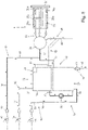
- reference number 1 indicates as a whole a home laundry washing machine which comprises: a preferably, though not necessarily, substantially parallelepiped-shaped, rigid outer boxlike casing 2 which is structured for resting on the floor; a preferably substantially cylindrical, bell-shaped hollow washing tub 3 which is arranged inside the casing 2 with its opening or mouth directly facing a laundry loading/unloading through opening realized in the front wall 2a of boxlike casing 2; a preferably substantially cylindrical, elastically-deformable bellows 4 watertight connecting the front opening or mouth of washing tub 3 to the laundry loading/unloading opening realized in the front wall 2a of casing 2; and a substantially cylindrical, bell-shaped rotatable drum (not shown) structured for housing the laundry to be washed, and which is housed in axially rotatable manner inside the washing tub 3, so as to be able to freely rotate about its longitudinal reference axis.
- the laundry loading/unloading opening is preferably realized on front wall 2a of casing 2 substantially astride of the vertical center-plane of the casing 2, and the washing tub 3 is preferably arranged inside the boxlike casing 2 with its longitudinal reference axis substantially horizontally-oriented, i.e. substantially perpendicular to front wall 2a.
- the rotatable drum (not shown), in turn, is housed in axially rotating manner inside the washing tub 3 with its front opening directly faced/aligned to the laundry loading/unloading opening on front wall 2a, and the drum rotation axis is preferably arranged locally substantially coincident with the substantially horizontally-oriented longitudinal reference axis of washing tub 3.
- the hollow washing tub 3 is preferably suspended in floating manner inside the casing 2 via a suspension system preferably, though not necessarily, comprising a couple of upper coil springs 5 connecting the upper portion of the washing tub 3 to the top of the boxlike casing 2, and a number of lower vibration dampers (not shown) connecting the bottom portion of the washing tub 3 to the bottom of casing 2.
- a suspension system preferably, though not necessarily, comprising a couple of upper coil springs 5 connecting the upper portion of the washing tub 3 to the top of the boxlike casing 2, and a number of lower vibration dampers (not shown) connecting the bottom portion of the washing tub 3 to the bottom of casing 2.
- the laundry washing machine 1 furthermore comprises:
- the laundry washing machine 1 furthermore comprises an appliance control panel 11 which is structured for allowing the user to manually select the desired washing-cycle and is located on front wall 2a of casing 2, above the laundry loading/unloading opening and close to a preferably substantially horizontally oriented, upper worktop or top wall 2b of the casing 2; and an internal water softening device 12 which is located inside the casing 2, and is structured for selectively reducing, during each washing cycle, the hardness degree of the fresh water flowing from the water mains to the detergent dispensing assembly 9 and/or to the washing tub 3.
- an appliance control panel 11 which is structured for allowing the user to manually select the desired washing-cycle and is located on front wall 2a of casing 2, above the laundry loading/unloading opening and close to a preferably substantially horizontally oriented, upper worktop or top wall 2b of the casing 2
- an internal water softening device 12 which is located inside the casing 2, and is structured for selectively reducing, during each washing cycle, the hardness degree of the fresh water flowing from the water mains
- the appliance control panel 11 is located on front wall 2a of the casing 2 substantially immediately beneath the worktop 2b of casing 2, preferably also so as to border the worktop 2b. Furthermore the appliance control panel 11 is preferably located substantially on the upper left corner of the front wall 2a.
- the appliance control panel 11 is preferably located substantially on the upper region of casing 2.
- the internal water softening device 12 is arranged/located along the fresh-water supply circuit 10, so as to be crossed by the fresh water flowing from the water mains to the detergent dispensing assembly 9 and/or the washing tub 3, and is internally provided with a given amount of water softening agent which is able to reduce the hardens degree of the fresh water flowing through the same water softening device 12, and with a given amount of consumable salt or other regeneration agent which is able to regenerate the water softening function of the water softening agent.
- the water softening device 12 is moreover provided with a loading inlet or mouth which is structured for allowing the user to timely load the consumable salt or other regeneration agent inside the same water softening device 12, and it is arranged/located inside the boxlike casing 2 so that the loading inlet or mouth of the same water softening device 12 is exposed or exposable to the outside on a portion of the worktop 2b located behind the appliance control panel 11.
- the exposed or exposable loading inlet or mouth of the water softening device 12 is arranged/located on a portion of the worktop 2b extending between the appliance control panel 11 and the back wall of the casing 2.
- the internal water softening device 12 is preferably arranged/located inside the boxlike casing 2 so that the loading inlet or mouth of the same water softening device 12 is exposed or exposable to the outside substantially immediately behind the appliance control panel 11.
- the loading inlet or mouth of water softening device 12 is freely accessible by the user on the worktop 2b through a manually-operated closure assembly 13 preferably arranged/ incorporated into the same worktop 2b.
- the loading inlet or mouth of water softening device 12 is preferably freely accessible by the user through a manually-operated trapdoor 13 realized on the worktop 2b of casing 2 preferably substantially immediately behind the appliance control panel 11.
- the manually-operated trapdoor 13 furthermore forms a portion of the worktop 2b of the casing 2.
- the door of the manually-operated trapdoor 13 is preferably movable to and from a closing position wherein the same door hides the loading inlet or mouth of the water softening device 12.
- the door of the manually-operated trapdoor 13 is preferably hinged to the worktop 2b of casing 2 so as to be able to rotate about a substantially horizontally-oriented reference axis preferably, though not necessarily, parallel to the reference laying plane of front wall 2a, between
- the worktop 2b of casing 2 is preferably, though not necessarily, also provided with a substantially-flat, inner shelf or panel 14 which is arranged immediately beneath the manually-operated trapdoor 13, that is to say beneath the manually-operated closure assembly 13, and the loading inlet or mouth of the water softening device 12 is preferably located/incorporated into this substantially-flat inner shelf 14.
- the detergent dispensing assembly 9 is provided with a corresponding loading inlet or mouth which is structured for allowing the user to timely load the requested detergent, softener and/or other washing agent inside the same detergent dispensing assembly 9.
- the detergent dispensing assembly 9 is arranged/located inside the boxlike casing 2 so that the loading inlet or mouth of the same detergent dispensing assembly 9 is exposed or exposable to the outside on front wall 2a of casing 2, preferably above the laundry loading/unloading opening and beneath the worktop 2b of the casing 2, i.e. between the worktop 2b and the laundry loading/unloading opening.
- the detergent dispensing assembly 9 is preferably arranged/ located inside the casing 2 so that the loading inlet or mouth of the same detergent dispensing assembly 9 is preferably exposed or exposable to the outside on front wall 2a, substantially horizontally beside the appliance control panel 11.
- the detergent dispensing assembly 9 is preferably arranged inside the casing 2 so as to locate its loading inlet or mouth immediately beneath the worktop 2b of the casing 2, substantially on the upper right corner of front wall 2a.
- the detergent dispensing assembly 9 and the appliance control panel 11 are preferably arranged inside the boxlike casing 2 substantially horizontally aligned to one another, immediately beneath the worktop 2b of casing 2.
- the fresh-water supply circuit 10 preferably comprises an electrically-controlled on-off valve 15 which is arranged/interposed between the water mains and the water softening device 12, and is able to control/regulate the flow of fresh water from the water mains towards the water softening device 12; a first pipeline 16 connecting the on-off valve 15 directly to the water inlet of the internal water softening device 12; and a second pipeline 17 connecting the water outlet of the internal water softening device 12 to the detergent dispensing assembly 9 and/or to the washing tub 3.
- an electrically-controlled on-off valve 15 which is arranged/interposed between the water mains and the water softening device 12, and is able to control/regulate the flow of fresh water from the water mains towards the water softening device 12
- a first pipeline 16 connecting the on-off valve 15 directly to the water inlet of the internal water softening device 12
- a second pipeline 17 connecting the water outlet of the internal water softening device 12 to the detergent dispensing assembly 9 and/or to the
- the fresh-water supply circuit 10 is preferably also provided with a one-way valve 18 which is located along pipeline 16 immediately downstream of the on-off valve 15, i.e. between the on-off valve 15 and the water inlet of the water softening device 12, and is structured to allow the fresh water to only flow along the pipeline 16 from the water mains to the water softening device 12 and not vice versa.
- a one-way valve 18 which is located along pipeline 16 immediately downstream of the on-off valve 15, i.e. between the on-off valve 15 and the water inlet of the water softening device 12, and is structured to allow the fresh water to only flow along the pipeline 16 from the water mains to the water softening device 12 and not vice versa.
- the internal water softening device 12 is therefore located downstream of the electrically-controlled on-off valve 15, and also downstream of the one-way valve 18 if present.
- the detergent dispensing assembly 9 instead preferably comprises a detergent container 20 which is manually fillable with a given quantity of detergent, softener and/or other washing agent, and is housed inside the casing 2 into a corresponding container housing 21; and the front wall 2a of casing 2 is preferably provided with a corresponding pass-through opening 21a through which the detergent container 20 is accessible by the user.
- the detergent container 20 is provided with a loading inlet or mouth which is structured for allowing the user to load the requested detergent, softener and/or other washing agent inside the same detergent container 20, and this loading inlet or mouth is accessible by the user through the pass-through opening 21a on front wall 2a.
- the quantity of detergent, softener and/or other washing agent stored into the detergent container 20 may be sufficient either for a single washing cycle or for several consecutive washing cycles.
- the container housing 21 is preferably located inside casing 2, above the washing tub 3 and beneath the worktop 2b, and the pass-through opening 21a is preferably arranged/located on front wall 2a of casing 2, immediately beneath the worktop 2b.
- the detergent dispensing assembly 9 furthermore comprises a water supply circuit 22 which is connected to the fresh-water supply circuit 10 downstream of the water softening device 12, and is structured for selectively channelling a given amount of fresh water arriving from the water mains into the detergent container 20, so as to selectively flush/push a given quantity of the detergent, softener or other washing agent into the washing tub 3.
- a water supply circuit 22 which is connected to the fresh-water supply circuit 10 downstream of the water softening device 12, and is structured for selectively channelling a given amount of fresh water arriving from the water mains into the detergent container 20, so as to selectively flush/push a given quantity of the detergent, softener or other washing agent into the washing tub 3.
- the inlet of water supply circuit 22 is fluidically connected to the fresh-water supply circuit 10, namely to the pipeline 17 of the fresh-water supply circuit 10, so as to receive the fresh water drawn from the water mains, and the water softening device 12 is located upstream of the water supply circuit 22 so as to be crossed by the fresh water flowing towards the water supply circuit 22.
- the detergent dispensing assembly 9 preferably comprises a detergent drawer 20 which is manually fillable with a given quantity of detergent, softener and/or other washing agent, and which is fitted/ inserted in manually extractable manner into a completely recessed drawer housing 21 which, starting from front wall 2a of casing 2, extends preferably substantially horizontally inside the boxlike casing 2 while remaining above the washing tub 3, and moreover communicates with the outside of casing 2 via a front entrance or opening 21a realized on front wall 2a of casing 2 substantially immediately above the laundry loading/unloading opening and substantially horizontally beside the appliance control panel 11.
- the bottom of drawer housing 21 is furthermore structured so to directly communicate with the inside of washing tub 3 via a corresponding connecting duct (not shown).
- the detergent drawer 20 is therefore manually movable inside the drawer housing 21 in a preferably substantially horizontally-oriented, displacement direction between a working position (see Figure 2 ) in which the detergent drawer 20 is completely recessed inside the corresponding drawer housing 21 preferably while at same time closing the front entrance or opening of the same drawer housing, and a completely extracted position (see Figure 1 ) in which the detergent drawer 20 partly juts out from the front wall 2a of casing 2 through the front entrance or opening 21a of the drawer housing 21.
- the drawer housing 21 of detergent drawer 20 is preferably arranged inside casing 2 so as to locate its front entrance or opening 21a immediately beneath the worktop 2b of casing 2, substantially on the upper right corner of front wall 2a of casing 2; whereas the detergent drawer 20 is preferably movable inside the same drawer housing 21 along a substantially horizontally-oriented, displacement direction which is also locally substantially perpendicular to front wall 2a of casing 2.
- the water supply circuit 22 is connected to the fresh-water supply circuit 10 downstream of the water softening device 12, and is structured for selectively spilling/pouring a given amount of fresh water arriving from the water mains into the detergent drawer 20, so as to selectively flush a given quantity of the detergent, softener or other washing agent into the washing tub 3.
- the water supply circuit 22 receives the fresh water from the fresh-water supply circuit 10, and is preferably structured for selectively spilling/pouring a dense shower of water droplets by gravity directly into the detergent drawer 20, so as to flush the detergent, softener or other washing agent out of the detergent drawer 20 and down onto the bottom of drawer housing 21.
- This mixture of water and detergent, softener or other washing agent afterwards flows into washing tub 3 via the connecting duct branching off from the bottom of the drawer housing 21 of detergent drawer 20.
- the detergent drawer 20 is preferably, though not necessarily, divided into a plurality of detergent compartments 20a (three detergent compartments in the example shown) each of which is manually fillable with a respective washing agent; and the water supply circuit 22 is structured for spilling/pouring the softened fresh water arriving from the fresh-water supply circuit 10 selectively and alternatively into any one of the detergent compartments 20a of detergent drawer 20, so as to selectively flush the detergent, softener or other washing agent out of the same compartment 20a and down onto the substantially funnel-shaped bottom of drawer housing 21 of detergent drawer 20.
- the water supply circuit 22 of detergent dispensing assembly 9 is provided with an electrically-controlled hydraulic distributor 24 or similar valve assembly, which is arranged/ interposed between the fresh-water supply circuit 10 and the various detergent compartments 20a of the detergent drawer 20, i.e. between the outlet of the pipeline 17 and the various detergent compartments 20a of detergent drawer 20, and is structured for selectively and alternatively channelling the fresh water arriving from the fresh-water supply circuit 10 towards the various detergent compartments 20a of detergent drawer 20.
- the water supply circuit 22 is preferably, though not necessarily, structured for spilling/pouring a dense shower of water droplets by gravity into the various detergent compartments 20a of the detergent drawer 20.
- the water supply circuit 22 preferably comprises a sprinkler head 25 which is associated to the drawer housing 21 of detergent drawer 20 so as to be located immediately above the detergent drawer 20 when the latter is completely inserted/recessed into the drawer housing 21.
- This sprinkler head 25 is provided with a number (three in the example shown) of shower-making portions/sections 25a each of which is preferably substantially vertically aligned to one or more detergent compartments 20a of detergent drawer 20, and is structured for feeding a dense shower of water droplets by gravity into said detergent compartment/s 20a.
- each shower-making section/portion 25a of sprinkler head 25 is preferably locally vertically aligned to a respective detergent compartment 20a of detergent drawer 20, and is preferably structured for feeding a dense shower of water droplets exclusively into the detergent compartment 20a located immediately beneath.
- the electrically-controlled hydraulic distributor or valve assembly 24 is located upstream of the sprinkler head 25, i.e. between the sprinkler head 25 and the fresh-water supply circuit 10, and is structured for channelling the fresh water arriving from the fresh-water supply circuit 10 selectively and alternatively towards the various shower-making sections/portions 25a of the sprinkler head 25.
- the electrically-controlled hydraulic distributor 24 is provided with a water inlet fluidically connected to the fresh-water supply circuit 10, i.e. to pipeline 17, and a number (three in the example shown) of water outlets each fluidically connected to a respective shower-making section/portion 25a of the sprinkler head 25, and it is structured for selectively and alternatively channelling the fresh water arriving from the fresh-water supply circuit 10 to the various shower-making sections/portions 25a of the sprinkler head 25.
- the internal water softening device 12 in turn basically comprises a water-softening agent container 28 and a regeneration-agent reservoir 29, both housed inside the boxlike casing 2.
- the water-softening agent container 28 is arranged/located along the fresh-water supply circuit 10 so as to be crossed by the fresh water flowing along the fresh-water supply circuit 10, and is filled with a water softening agent able to reduce the hardness degree of the fresh water flowing through the same water-softening agent container 28.
- the regeneration-agent reservoir 29 instead is structured for receiving a given quantity of consumable salt or other regeneration agent which is able to regenerate the water softening function of the water softening agents stored inside the water-softening agent container 28, and is fluidically connected to the water-softening agent container 28 for selectively transferring a mixture of water and salt or other regeneration agent to the water-softening agent container 28.
- the water-softening agent container 28 has an inlet connected to pipeline 16 of fresh-water supply circuit 10 and an outlet connected to pipeline 17 of fresh-water supply circuit 10, so as to be crossed by the fresh water flowing from the water mains to the detergent dispensing assembly 9.
- the water-softening agent container 28 is therefore fluidically interposed between the water mains and the detergent dispensing assembly 9, or more specifically between the water mains and the inlet of the water supply circuit 22 of detergent dispensing assembly 9, so as to be crossed by the fresh water flowing from the water mains to the inlet of water supply circuit 22.
- the regeneration-agent reservoir 29 is provided with an exposable loading inlet or mouth which is structured for allowing the user to timely load the consumable salt or other regeneration agent inside the same regeneration-agent reservoir 29, thus forming the exposable loading inlet or mouth of the internal water softening device 12, and it is arranged/located inside the casing 2 so that the loading inlet or mouth of the same regeneration-agent reservoir 29 is exposed or exposable to the outside on worktop 2b of casing 2, substantially immediately behind the appliance control panel 11.
- the water-softening agent container 28 is filled with a given amount of ion-exchange resins (not shown) capable to restrain the calcium and/or magnesium ions (Ca++ an Mg++) dissolved in the fresh water flowing across the same water-softening agent container 28, and is located along the fresh-water supply circuit 10 so as to be crossed by the fresh water directed towards the detergent dispensing assembly 9 and/or the washing tub 3.
- ion-exchange resins not shown
- Ca++ an Mg++ calcium and/or magnesium ions
- the water-softening agent container 28, hereinafter also referred to as the resin container 28, is preferably arranged between pipelines 16 and 17, so as to be crossed by the fresh water directed towards the detergent dispensing assembly 9 and/or the washing tub 3, and it is furthermore arranged upstream of the hydraulic distributor 24 of detergent dispensing assembly 9, so as to be crossed by the fresh water flowing from the water mains to the inlet of water supply circuit 22.
- the ion-exchange resins (not shown) stored into the water-softening agent container 28 form the water softening agents of the water softening device 12.
- the outside-accessible regeneration-agent reservoir 29, in turn, is structured for receiving a given amount (for example half a Kilo or one Kilo) of salt grains (Sodium Chloride) or similar regeneration chemical agent, and is located/arranged inside the casing 2, immediately beneath the worktop 2b of casing 2, so as to be freely accessible by the user through the worktop 2b of casing 2, substantially immediately behind the appliance control panel 11.
- a given amount for example half a Kilo or one Kilo
- salt grains sodium Chloride
- the loading inlet or mouth of the regeneration-agent reservoir 29 is preferably freely accessible by the user through the trapdoor 13 realized on worktop 2b of casing 2, substantially immediately behind the appliance control panel 11.
- the regeneration-agent reservoir 29 is preferably arranged immediately underneath the inner shelf 14 of worktop 2b, and the loading inlet or mouth of regeneration-agent reservoir 29 is preferably located/ incorporated into the inner shelf 14 so as to be freely accessible by the user when the trapdoor 13 is arranged in the raised/opened position.
- the water-softening agent container 28 is preferably located immediately underneath the regeneration-agent reservoir 29, so as to be substantially vertically aligned to the regeneration-agent reservoir 29 which, in turn, is preferably located immediately beneath the trapdoor 13 realized on worktop 2b of boxlike casing 2.
- the internal water softening device 12 furthermore comprises:
- the electrically-powered brine-circulating pump 31 is furthermore structured for transferring/moving, when activated, the brine (i.e. the salt water) from the regeneration-agent reservoir 29 to the water-softening agent container 28, and for completely watertight sealing/isolating, when deactivated, the regeneration-agent reservoir 29 from the water-softening agent container 28 so as to prevent the brine (i.e. the salt water) store in the regeneration-agent reservoir 29 from flowing towards the water-softening agent container 28.
- the brine i.e. the salt water
- the electrically-powered brine-circulating pump 31 may be replaced by an electrically-powered pump assembly comprising a conventional electrically-powered suction pump and an on-off valve which is arranged immediately upstream of the suction pump and is structured to watertight seal the suction/inlet of the electrically-powered suction pump when the latter is deactivated, and to put the suction/inlet of the electrically-powered suction pump in direct communication with the inside of the regeneration-agent reservoir 29 when the suction pump is activated.
- an electrically-powered pump assembly comprising a conventional electrically-powered suction pump and an on-off valve which is arranged immediately upstream of the suction pump and is structured to watertight seal the suction/inlet of the electrically-powered suction pump when the latter is deactivated, and to put the suction/inlet of the electrically-powered suction pump in direct communication with the inside of the regeneration-agent reservoir 29 when the suction pump is activated.
- the water softening device 12 is furthermore provided with a water-level sensor (not shown) which is structured for measuring the level of the brine contained into the regeneration-agent reservoir 29, and/or a salinity-level sensor (not shown) which is structured for measuring the salinity degree of the brine contained into the regeneration-agent reservoir 29.
- a water-level sensor (not shown) which is structured for measuring the level of the brine contained into the regeneration-agent reservoir 29
- a salinity-level sensor (not shown) which is structured for measuring the salinity degree of the brine contained into the regeneration-agent reservoir 29.
- the water-level sensor and/or the salinity-level sensor is/are able to communicate with an internal electronic central control unit (not shown) which is housed inside the boxlike casing 2 and controls all electrically-operated component parts of the laundry washing machine 1.
- the regeneration-agent reservoir 29 preferably comprises a substantially basin-shaped, regeneration-agent container 33 which is manually fillable with a given quantity of consumable salt or other regeneration agent, and is recessed/incorporated into the inner shelf 14 of worktop 2b, on a portion of the worktop 2b located behind the appliance control panel 11, so that its upper mouth 33a is freely accessible by the user when the trapdoor 13 is arranged in the raised position.
- the regeneration-agent container 33 is preferably recessed/incorporated into the inner shelf 14 of worktop 2b, substantially immediately behind the appliance control panel 1.
- the water supply circuit 30, in turn, is structured for channelling, on command, a given amount of fresh water into the basin-shaped container 33 so to at least partly dissolve the salt or other regeneration agents stored therein and form a given amount of brine (i.e. of salt water), and the suction of the brine-circulating pump 31 directly communicates with said regeneration-agent container 33, so that the brine-circulating pump 31 is able to selectively pump the brine from the basin-shaped container 33 to the resin container 28.
- brine i.e. of salt water
- the upper mouth 33a of the basin-shaped container 33 allows the user to load the consumable salt or other regeneration agent inside the regeneration-agent reservoir 29, and therefore forms the exposable loading inlet or mouth of the water softening device 12.
- the bottom of the substantially basin-shaped, regeneration-agent container 33 is preferably, though not necessarily, shaped/structured so as to form a gulley or sump 33b wherein the brine tends to accumulate, and the suction of the brine-circulating pump 31 directly communicates with said gulley or sump 33b, so that the brine-circulating pump 31 is able to selectively pump the brine from the bottom of the basin-shaped container 33 to the resin container 28.
- the water softening device 12 furthermore comprises a water-level sensor (not shown) which is structured for measuring the level of the brine contained into the basin-shaped container 33, and/or a salinity-level sensor (not shown) which is structured for measuring the salinity degree of the brine contained into the basin-shaped container 33.
- a water-level sensor (not shown) which is structured for measuring the level of the brine contained into the basin-shaped container 33
- a salinity-level sensor (not shown) which is structured for measuring the salinity degree of the brine contained into the basin-shaped container 33.
- the water supply circuit 30 of water softening device 12 is preferably structured for being connected to the water mains independently from the fresh-water supply circuit 10, so as to be able to selectively draw a given amount of fresh water from the water mains and channel said fresh water directly into the regeneration-agent reservoir 29.
- the water supply circuit 30 is connected to the water mains independently from the fresh-water supply circuit 10, and is preferably structured for spilling/pouring a shower of the water droplets by gravity directly into the basin-shaped container 33.
- the water supply circuit 30 of water softening device 12 preferably comprises:
- the electrically-controlled on-off valve 36 is preferably, though not necessarily, attached to the rear wall of casing 2 close to on-off valve 15, and it is directly connected to the sprinkler nozzles 35 via a pipeline 37 or the like.
- the electrically-controlled on-off valve 36 is furthermore preferably, though not necessarily, dimensioned so as to have a nominal flow rate substantially equal to the nominal flow rate of the brine-circulating pump 31, so that the brine-circulating pump 31 is able to transfer/move the brine little by little from the regeneration-agent reservoir 29 to the resin container 28, thus minimising the permanency of the brine on the bottom of basin-shaped container 33.
- the regeneration-agent reservoir 29 may also comprise a manually-removable upper lid which is shaped/structured so as to substantially completely cover and close the upper mouth 33a of the basin-shaped container 33; and the water supply circuit 30 of water softening device 12 preferably comprises, in place of the perimetrical sprinkler nozzles 35, a huge sprinkler head which is incorporated into said manually-removable upper lid so as to be faced with the inside of the basin-shaped container 33 when the lid closes the upper mouth 33a of the basin-shaped container 33, and is structured for feeding a dense shower of water droplets by gravity into the basin-shaped container 33.
- the huge sprinkler head may be also incorporated into the trapdoor 13 so as to be vertically aligned to the upper mouth 33a of the basin-shaped container 33, when the trapdoor 13 is arranged in the lowered/closed position.
- the water supply circuit 30 of water softening device 12 furthermore comprises an additional one-way valve 38 which is located immediately downstream of the on-off valve 36, i.e. between the on-off valve 37 and the sprinkler nozzles 35, and which is structured to allow the fresh water to only flow along the pipeline 37 from the water mains to the sprinkler nozzles 35.
- the resin container 28 is preferably, though not necessarily, attached to the bottom of the substantially basin-shaped, regeneration-agent container 33, immediately beside the upper portion of washing tub 3, so as to internally face the front wall 2a of casing 2.
- the resin container 28 is preferably located below the regeneration-agent container 33 located behind the appliance control panel 11, within an approximately triangular pocket seat or compartment delimited by the bottom of the regeneration-agent container 33, the front wall 2a of casing 2, the vertical sidewall of the same casing 2, and the upper portion of washing tub 3.
- the resin container 28 preferably, though not necessarily, consists in a completely stand-alone modular cartridge 28 which is provided with mechanical coupling members (not shown) structured for allowing a rigid and stable, though easily releasable, fastening of the stand-alone modular component-part or cartridge 28 directly to the bottom of the substantially basin-shaped, regeneration-agent container 33, and with hydraulic connectors (not shown) structured for allowing the stable, though easily removable, fluidical connection of the stand-alone modular cartridge 28 to the fresh water supply circuit 10 and to the outlet of the brine-circulating pump 31.
- mechanical coupling members not shown
- hydraulic connectors not shown
- a first hydraulic connector (not shown) of the stand-alone modular cartridge 28 is connected to pipeline 16, so as to allow the inflow of the fresh water into the resin container 28;
- a second hydraulic connector (not shown) of the stand-alone modular cartridge 28 is connected to pipeline 17 so as to allow the outflow of the fresh water from the resin container 28 towards the detergent dispensing assembly 9;
- a third hydraulic connector (not shown) of the stand-alone modular cartridge 28 is structured to directly communicate with the outlet of the brine-circulating pump 31 so as to allow the controlled inflow of the brine (i.e. the salt water) into the resin container 28.
- the internal water softening device 12 is preferably, though not necessarily, also provided with a first water drain line 39 which fluidically connects the resin container 28, i.e. the water-softening agent container 28, to the washing tub 3 and is structured for selectively draining the brine or fresh water out of the resin container 28 and channelling said brine or fresh water directly into the washing tub 3.
- a first water drain line 39 which fluidically connects the resin container 28, i.e. the water-softening agent container 28, to the washing tub 3 and is structured for selectively draining the brine or fresh water out of the resin container 28 and channelling said brine or fresh water directly into the washing tub 3.
- the water drain line 39 is structured for channelling the brine or fresh water stored into the resin container 28, preferably into the drain sump (not shown) that extends downwards form the bottom of the washing tub 3, or into the water filtering assembly (not shown) that is interposed between the drain sump (not shown) of washing tub 3 and the suction of either the water circulating pump (not shown) or the water exhaust pump (not shown), or substantially directly into the water exhaust pump (not shown) which drains the waste water or washing liquor outside of the laundry washing machine 1, or in any case into the waste-water drain line that channels the waste water or washing liquor outside the laundry washing machine 1.
- the water drain line 39 preferably comprises a pipeline 40 or the like which directly connects the bottom of the resin container 28 to the washing tub 3, or to the drain sump (not shown), or to the water filtering assembly (not shown), or to the water exhaust pump (not shown); and an electrically-controlled on-off valve 41 which is located along the pipeline 40 for controlling the outflow of the brine or fresh water from the resin container 28.
- the internal water softening device 12 is preferably also provided with a water-hardness sensor (not shown) structured for measuring the hardness degree of the fresh water coming out from the resin container 28, i.e. the water-softening agent container 28, directed towards the detergent dispensing assembly 9 or the washing tub 3.
- a water-hardness sensor structured for measuring the hardness degree of the fresh water coming out from the resin container 28, i.e. the water-softening agent container 28, directed towards the detergent dispensing assembly 9 or the washing tub 3.
- the water-hardness sensor is able to communicate with an internal electronic central control unit (not shown) which is housed inside the boxlike casing 2 and controls all electrically-operated component parts of the laundry washing machine 1.
- the laundry washing machine 1 is preferably, though not necessarily, also provided with a second water drain line 43 which is structured for selectively rerouting the brine or fresh water coming out from the resin container 28 directed towards the detergent dispensing assembly 9, into the washing tub 3 so as to bypass at least the detergent container 20, i.e. the detergent drawer 20, of the detergent dispensing assembly 9.
- a second water drain line 43 which is structured for selectively rerouting the brine or fresh water coming out from the resin container 28 directed towards the detergent dispensing assembly 9, into the washing tub 3 so as to bypass at least the detergent container 20, i.e. the detergent drawer 20, of the detergent dispensing assembly 9.
- the water drain line 43 is structured for channeling the brine or fresh water coming out from the resin container 28 directed towards the detergent dispensing assembly 9, preferably into the drain sump (not shown) that extends downwards form the bottom of washing tub 3, or into the water filtering assembly (not shown) that is interposed between the drain sump (not shown) of washing tub 3 and the suction of the water circulating pump (not shown) and/or of the water exhaust pump (not shown) of the laundry washing machine 1, or in any case into the waste-water drain line that channels the waste water or washing liquor outside the laundry washing machine 1.
- the second water drain line 43 is structured to selectively reroute the brine or fresh water that enters into the detergent dispensing assembly 9 through pipeline 17, directly towards the washing tub 3, or towards the drain sump (not shown) that extends downwards form the bottom of washing tub 3, or towards the water filtering assembly (not shown) that is interposed between the drain sump (not shown) of washing tub 3 and the suction of the water circulating pump (not shown) and/or of the water exhaust pump (not shown) of the laundry washing machine 1, so as to bypass solely the detergent container 20, i.e. the detergent drawer 20, of detergent dispensing assembly 9.
- the second water drain line 43 preferably comprises a pipeline 44 or the like which is connected to a specific additional water outlet of the electrically-controlled hydraulic distributor 24 or similar valve assembly of the detergent dispensing assembly 9, and ends directly into the washing tub 3, or into the drain sump, or into the water filtering assembly, or into the water exhaust pump; and the electrically-controlled hydraulic distributor 24 is structured to selectively direct/channel directly into pipeline 44 the brine of softened fresh water arriving from resin container 28 via pipeline 17, so as to channel the brine or fresh water arriving from resin container 28 directly into the washing tub 3 or into the drain sump (not shown) or into the water filtering assembly (not shown) or into the water exhaust pump (not shown).
- the second water drain line 43 of fresh-water supply circuit 10 may comprise, immediately upstream of the water supply circuit 22 of detergent dispensing assembly 9, an electrically-controlled three-way valve which has a first outlet connected to the inlet of the water supply circuit 22, i.e. to the hydraulic distributor 24, and a second outlet connected to pipeline 44 of water drain line 43.
- This electrically-controlled three-way valve is structured for selectively and alternatively channelling the fresh water coming out of the resin container 28 either to pipeline 44, or to the inlet of the water supply circuit 22 of detergent dispensing assembly 9, i.e. to the hydraulic distributor 24.
- the second water drain line 43 is structured so as to bypass the whole detergent dispensing assembly 9, and therefore the water supply circuit 22 of detergent dispensing assembly 9 may lack the hydraulic distributor 24.
- the laundry washing machine 1 is finally provided with a second fresh-water supply circuit 46 which is connectable to the water mains independently from the fresh-water supply circuit 10, and which is structured for selectively channelling the fresh water from the water mains to the detergent dispensing assembly 9 and/or directly to the washing tub 3, bypassing the water softening device 12, or better the of the resin container 28 of the water softening device 12.
- a second fresh-water supply circuit 46 which is connectable to the water mains independently from the fresh-water supply circuit 10, and which is structured for selectively channelling the fresh water from the water mains to the detergent dispensing assembly 9 and/or directly to the washing tub 3, bypassing the water softening device 12, or better the of the resin container 28 of the water softening device 12.
- the second fresh-water supply circuit 46 connects the water mains directly to the inlet of the water supply circuit 22 of detergent dispensing assembly 9 bypassing the water softening device 12, and is structured so as to selectively channel to the inlet of the water supply circuit 22 a second flow of non-softened fresh water of the water mains.
- the second fresh-water supply circuit 46 is therefore able to channel the fresh water of the water mains directly towards the inlet of water supply circuit 22 independently from the fresh-water supply circuit 10.
- the second fresh-water supply circuit 46 is preferably, though not necessarily, also able to channel the non-softened fresh water of the water mains directly to the washing tub 3 via the water drain line 43, thus bypassing all detergent compartments 20a of the detergent drawer 20.
- the second fresh-water supply circuit 46 preferably comprises:
- the second fresh-water supply circuit 46 preferably also comprises a second one-way valve 49 which is located downstream of the on-off valve 47, and is structured to allow the fresh water to only flow along the pipeline 48, from the water mains to the inlet of the water supply circuit 20 of detergent dispensing assembly 9, and not vice versa.
- a second one-way valve 49 which is located downstream of the on-off valve 47, and is structured to allow the fresh water to only flow along the pipeline 48, from the water mains to the inlet of the water supply circuit 20 of detergent dispensing assembly 9, and not vice versa.
- the appliance control panel 11 is furthermore structured so as to allow the user to manually select the desired washing cycle between washing cycles that use softened fresh water, washing cycles that use normal, i.e. non-softened, fresh water, and finally washing cycles that use a mixture of softened and normal, i.e. non-softened, fresh water.
- the softened fresh water of the water mains reaches the detergent dispensing assembly 9 and enters into the electrically-controlled hydraulic distributor 24 of water supply circuit 22.
- the hydraulic distributor 24 then channels the softened fresh water to one or more of the shower-making portions/sections 25a of the sprinkler head 25 for flushing the detergent, softener or other washing agent out of the corresponding detergent compartment 20a of the detergent drawer 20 and sweeping away said detergent, softener or other washing agent down into the washing tub 3 via the connecting duct on the bottom of the drawer housing 21 of detergent drawer 20.
- the electronic central control unit (not shown) of laundry washing machine 1 When determines that the ion-exchange resins inside the resin container 28 are no more able to reduce the hardness degree of the fresh water directed to the washing tub 3, the electronic central control unit (not shown) of laundry washing machine 1 performs, preferably immediately before the starting of the rinsing phase of the washing cycle, a regeneration process of the ion-exchange resins stored inside the resin container 28.
- the regeneration process may also take place during the washing phase of the washing cycle, or can take place even when no washing cycle at all is running, preferably on specific request of the user.
- the central control unit of laundry washing machine 1 firstly opens the on-off valve 36 of the water supply circuit 30 for enough time to channel into the regeneration-agent reservoir 29, i.e. into the basin-shaped container 33, an amount of fresh water sufficient to form, into the regeneration-agent reservoir 29, the whole amount of brine necessary for the resin regeneration process to take place.
- the central control unit of laundry washing machine 1 can keep the on-off valve 15 of fresh-water supply circuit 10 either in the closed position or in the opened position according to current phase of the washing cycle.
- the central control unit of laundry washing machine 1 closes the on-off valve 15 of the fresh-water supply circuit 10 to stop the flow of fresh water across the resin container 18, and preferably arranges the hydraulic distributor 24 of detergent dispensing assembly 9 so as to channel the fresh water arriving from the resin container 28 directly into the second water drain line 43.
- the central control unit of laundry washing machine 1 activates the brine-circulating pump 31 to transfer/move the whole amount of brine at a time from the regeneration-agent reservoir 29 to the resin container 28. Since the resin container 28 is completely filled with the fresh water of the water mains, the brine entering into the resin container 28 pushes out of the resin container 28 the fresh water previously stored therein. This fresh water flows along pipeline 17 towards the hydraulic distributor 24 which, in turn, directs/channels said fresh water directly into the second water drain line 43.
- the brine accumulates on the bottom of the basin-shaped container 33, and the brine-circulating pump 31 sucks the brine from the bottom of the same basin-shaped container 33.
- the central control unit of laundry washing machine 1 deactivates the brine-circulating pump 31 to watertight isolate the resin container 28 from the regeneration-agent reservoir 29, and to restrain the brine inside the resin container 28 for a predetermined time interval generally sufficient to allow the brine to remove from the ion-exchange resins the calcium and magnesium ions previously combined/fixed to said resins.
- the central control unit of laundry washing machine 1 opens again the on-off valve 15 of fresh-water supply circuit 10, so that the pressurized fresh water of the water mains pushes the brine out of the resin container 28 and into the pipeline 17 which channels the brine towards the hydraulic distributor 24 which, in turn, directs/channels said fresh water directly into the second water drain line 43.
- the central control unit of laundry washing machine 1 may open the on-off valve 41 of the first water drain line 39 so to drain the brine out of the resin container 28 through the water drain line 39.
- the brine stored in the resin container 28 therefore flows directly into the washing tub 3 or into the drain sump or into the water filtering assembly, or into the water exhaust pump, via the water drain line 39 and/or via the water drain line 43.
- the central control unit of the laundry washing machine 1 activates the water exhaust pump so to discharge the brine out of the laundry washing machine 1 preferably together with the washing or rinsing water already stored on the bottom of the washing tub 3, and continues the washing cycle.
- the second fresh-water supply circuit 46 can channel the fresh water of the water mains towards the inlet of water supply circuit 22 bypassing the water softening device 12, so to channel the non-softened fresh water of the water mains directly towards the inlet of the water supply circuit 22 of detergent dispensing assembly 9.
- the water supply circuit 22 of detergent dispensing assembly 9 therefore can channel towards any one of the detergent compartments 20a of detergent drawer 20, or towards the second water drain line 43 if connected to the hydraulic distributor 24, either softened, non-softened (i.e. normal) fresh water of the water mains or a mixture thereof.
- the laundry washing machine 1 is therefore able to use, during each stage of the washing cycle, either softened or non-softened fresh water of the water mains or a mixture thereof.
- the second fresh-water supply circuit 43 in fact, can channel non-softened fresh water to the inlet of the water supply circuit 22 of detergent dispensing assembly 9 independently from the fresh-water supply circuit 10, thus also at the same time of the fresh-water supply circuit 10.
- the electronic central control unit of the laundry washing machine 1 may be programmed to regenerate the ion-exchange resins stored in the resin container 28 after a given number of washing cycles. This number of washing cycles may be decided by the user on the basis of an alleged hardness degree of the fresh water coming out from the water mains.
- the water supply circuit 30 preferably branches off from the fresh-water supply circuit 10 downstream of resin container 28, so as to selectively channel into the regeneration-agent reservoir 29 the softened fresh water coming out of resin container 28.
- the water supply circuit 30 lacks the on-off valve 36 and instead comprises an electrically-controlled three-way valve 50 which is arranged along the fresh-water supply circuit 10, downstream of resin container 28, i.e. along the pipeline 17 connecting the outlet of resin container 28 to the inlet of the water supply circuit 22 of detergent dispensing assembly 9.
- the pipeline 37 of water supply circuit 30 is now connected to the three-way valve 50, and the electrically-controlled three-way valve 50 is structured for selectively and alternatively channelling the fresh water coming out of the resin container 28, to the sprinkler nozzles 35 for producing the brine, or to the inlet of the water supply circuit 22 of detergent dispensing assembly 9 for performing the washing cycle.
- the central control unit of laundry washing machine 1 sets the three-way valve 50 of water supply circuit 30 so as to put the outlet of resin container 28 in direct communication with the sprinkler nozzles 35, and afterwards opens the on-off valve 15 of the fresh-water supply circuit 10 for enough time to channel into the regeneration-agent reservoir 29 the whole amount of fresh water necessary to form, on the bottom of the basin-shaped container 33, an amount of brine sufficient for the resin regeneration process to take place.
- This amount of fresh water obviously flows across the resin container 28 before reaching the regeneration-agent reservoir 29.
- the central control unit of laundry washing machine 1 sets the three-way valve 50 so as to put again the outlet of resin container 28 in direct communication with the detergent dispensing assembly 9, and afterwards activates the brine-circulating pump 31 to transfer/move the whole amount of brine at a time from the regeneration-agent reservoir 29, i.e. from the bottom of the basin-shaped container 33, to the resin container 28.
- the central control unit of laundry washing machine 1 deactivates the brine-circulating pump 31 to watertight isolate the resin container 28 from the regeneration-agent reservoir 29.
- the water supply circuit 30 preferably branches off from the water supply circuit 22 of detergent dispensing assembly 9, so as to selectively channel into the regeneration-agent reservoir 29 the softened fresh water entering into the detergent dispensing assembly 9.
- the water supply circuit 30 lacks the on-off valve 36 and the pipeline 37 of water supply circuit 30 is now connected to a specific additional water outlet of the electrically-controlled hydraulic distributor 24 of water supply circuit 22, and the electrically-controlled hydraulic distributor 24 is structured to selectively direct/channel into pipeline 37 the softened fresh water or brine arriving from resin container 28 via pipeline 17.
- the central control unit of laundry washing machine 1 firstly arranges the hydraulic distributor 24 so as to channel towards the water supply circuit 30 the fresh water that arrives to the hydraulic distributor 24 from the resin container 28, and afterwards it opens the on-off valve 15 for enough time to channel into the regeneration-agent reservoir 29, the whole amount of fresh water necessary to form, on the bottom of the basin-shaped container 33, an amount of brine sufficient for the resin regeneration process to take place.
- This amount of fresh water obviously flows across the resin container 28 and the hydraulic distributor 24 of detergent dispensing assembly 9 before reaching the regeneration-agent reservoir 29.
- the central control unit of laundry washing machine 1 sets/arranges the hydraulic distributor 24 of water supply circuit 22 so as to put the outlet of resin container 28 in communication with the second water drain line 43, and afterwards activates the brine-circulating pump 31 to transfer/move the whole amount of brine at a time from the regeneration-agent reservoir 29, i.e. from the bottom of the basin-shaped container 33, to the resin container 28.
- the central control unit of laundry washing machine 1 deactivates the brine-circulating pump 31 to watertight isolate the resin container 28 from the regeneration-agent reservoir 29.
- the laundry washing machine 1 can use normal fresh water, thus lengthening the time between the regenerations of the ion-exchange resins.
- the appliance control panel 11 may be structured so as to allow the user to manually select washing cycles that use softened fresh water, washing cycles that use normal, i.e. non-softened, fresh water, and finally washing cycles that use a mixture of softened and normal, i.e. non-softened, fresh water.
- the regeneration-agent reservoir 29 comprises: a preferably substantially parallelepiped-shaped, storage tank 51 which is structured for being manually fillable with a given quantity of consumable salt or other regeneration agent, and which is arranged/located immediately underneath the worktop 2b of casing 2 on a portion of the worktop 2b arranged behind the appliance control panel 11, so as to be freely accessible by the user from worktop 2b of casing 2 preferably through the manually-operated trapdoor or similar closure assembly 13 realized on the worktop 2b of casing 2; and a manually-removable cap 52 which is structured to close the storage tank 51, and is preferably located on top of storage tank 51 so as to be freely accessible by the user.
- the storage tank 51 is preferably arranged/located immediately underneath the worktop 2b of casing 2, preferably substantially immediately behind the appliance control panel 11, so that at least the manually removable cap 52 of storage tank 51 is freely accessible by the user when the trapdoor or similar manually-operated closure assembly 13 is arranged in the raised/opened position (see Figure 7 ), and is completely hidden and inaccessible by the user when the trapdoor or closure assembly 13 is arranged in the lowered/ closed position.
- the manually-removable cap 52 allows the user to easily load the consumable salt or other regeneration agent inside the regeneration-agent reservoir 29, and therefore forms the exposable loading inlet or mouth of the water softening device 12.
- the water supply circuit 30 of water softening device 12 is preferably structured for channelling, on command, a given amount of fresh water from the water mains directly into the storage tank 51, so as to preferably completely dissolve at once the whole salt or other regeneration agents contained into storage tank 51 and form a great amount of brine (i.e. of salt water).
- the water supply circuit 30 of water softening device 12 is preferably no more provided with the sprinkler nozzles 35, and the pipeline 37 directly connects the electrically-controlled on-off valve 36 to storage tank 51.
- the water supply circuit 30 of water softening device 12 may also branch off from the fresh-water supply circuit 10 upstream of the detergent dispensing assembly 9 as disclosed in Figure 5 , or may branch off from the water supply circuit 22 of detergent dispensing assembly 9 as disclosed in Figure 6 , so as to selectively channel into the regeneration-agent reservoir 29 the softened fresh water entering into the detergent dispensing assembly 9.
- the electrically-powered brine-circulating pump 31 is structured for selectively and alternatively sucking the brine (i.e. the salt water) from the storage tank 51 and delivery it to the water-softening agent container 28, or completely watertight sealing/isolating the storage tank 51 from the water-softening agent container 28, so as to prevent the brine (i.e. the salt water) contained into the storage tank 51 from flowing towards the water-softening agent container 28.
- the electrically-powered brine-circulating pump 31 is structured for selectively and alternatively sucking the brine (i.e. the salt water) from the storage tank 51 and delivery it to the water-softening agent container 28, or completely watertight sealing/isolating the storage tank 51 from the water-softening agent container 28, so as to prevent the brine (i.e. the salt water) contained into the storage tank 51 from flowing towards the water-softening agent container 28.
- the water softening device 12 preferably furthermore comprises a water-level sensor (not shown) which is structured for measuring the level of the fresh water and/or brine contained inside the storage tank 51, and/or a salinity-level sensor (not shown) which is structured for measuring the salinity degree of the brine contained inside the storage tank 51.
- a water-level sensor (not shown) which is structured for measuring the level of the fresh water and/or brine contained inside the storage tank 51
- a salinity-level sensor (not shown) which is structured for measuring the salinity degree of the brine contained inside the storage tank 51.
- the storage tank 51 is preferably recessed /incorporated, either in a manually removable or unmovable manner, into the substantially-flat inner shelf 14 located beneath the manually-operated trapdoor 13, and is moreover dimensioned to contain an amount of brine sufficient for performing several resin regeneration processes. Furthermore the storage tank 51 is arranged into the substantially-flat inner shelf 14 substantially immediately behind the appliance control panel 11, so that at least the manually-removable cap 52 of storage tank 51 is freely accessible by the user when the trapdoor 13 is arranged in the raised position (see Figure 7 ), and is completely hidden and inaccessible by the user when the trapdoor 13 is arranged in the lowered position.
- the storage tank 51 of regeneration-agent reservoir 29 is preferably unmovably recessed/housed into the substantially-flat inner shelf 14, and the water softening device 12 is preferably provided with a preferably substantially basin-shaped, leakage collector 53 which is realized on the substantially-flat inner shelf 14 or on the worktop 2b so as collect the brine or water accidentally coming out from the storage tank 51 during refilling of the consumable salt.
- the water softening device 12 is furthermore provided with a third water drain line 54 which fluidically connects the leakage collector 53 on the inner shelf 14 or worktop 2b to the washing tub 3, and is structured to directly channel the water or brine accumulating into the leakage collector 53 towards the washing tub 3.
- a third water drain line 54 which fluidically connects the leakage collector 53 on the inner shelf 14 or worktop 2b to the washing tub 3, and is structured to directly channel the water or brine accumulating into the leakage collector 53 towards the washing tub 3.
- the water drain line 54 may be structured for channeling the brine or fresh water accumulating into the leakage collector 53 preferably into the drain sump (not shown) that extends downwards form the bottom of the washing tub 3, or into the water filtering assembly (not shown) that is interposed between the drain sump (not shown) of washing tub 3 and the suction of either the water circulating pump (not shown) or the water exhaust pump (not shown), or substantially directly into the water exhaust pump (not shown) which drains the waste water or washing liquor outside of the laundry washing machine 1, or in any case into the waste-water drain line that channels the waste water or washing liquor outside the laundry washing machine 1.
- the regeneration-agent reservoir 29 furthermore comprises, in addition or alternatively to the drain line 54, an overflow drain line 55 which fluidically connects the storage tank 51 to the washing tub 3, and is structured for directly channelling the water or brine eventually exceeding the maximum capacity of the storage tank 51 towards the washing tub 3.
- overflow drain line 55 may alternatively be structured to channel the water or brine eventually exceeding the maximum capacity of the storage tank 51 towards the drain sump, or towards the water filtering assembly, or towards the water exhaust pump, or in any case towards the waste-water drain line that channels the waste water or washing liquor outside the laundry washing machine 1.
- the regeneration-agent reservoir 29 is housed in manually removable manner into the boxlike casing 2.
- the storage tank 51 is preferably recessed in manually extractable manner into a corresponding preferably substantially basin-shaped, complementary tank seat 57 realized on the inner shelf 14 located beneath the manually-operated trapdoor 13, behind the appliance control panel 11, and is preferably provided with two self-closing hydraulic connectors 58 and 59 which are structured to hydraulically connect the storage tank 51 in easily detachable manner to, respectively, the water supply circuit 30 and the suction of the brine-circulating pump 31, preferably during insertion of the storage tank 51 into the tank seat 57.
- each self-closing hydraulic connector 58, 59 of storage tank 51 is specifically structured to watertight couple in easily detachable manner with a corresponding complementary, preferably self-closing, hydraulic connector 60, 61 arranged on the inner shelf 14 of worktop 2b.
- the self-closing hydraulic connector 60 directly communicates with the water supply circuit 30 of water softening device 12 and, when suitably coupled to the self-closing hydraulic connector 58, allows the fresh water arriving from water supply circuit 30 to freely flow into storage tank 51.
- the self-closing hydraulic connector 61 directly communicates with the suction of the brine-circulating pump 31, and allows, when suitably coupled to the self-closing hydraulic connector 59, the brine stored into the storage tank 51 to freely flow out of the storage tank 51 towards the brine-circulating pump 31.
- Each self-closing hydraulic connector 58, 59 of storage tank 51 is furthermore structured so as to remain closed in watertight manner when uncoupled from the corresponding complementary self-closing hydraulic connector 60, 61 of the drawer-like supporting structure 13.
- each self-closing hydraulic connector 60, 61 of drawer-like supporting structure 13 is preferably structured so as to remain closed in watertight manner when uncoupled from the corresponding complementary self-closing hydraulic connector 58, 59 of storage tank 51.
- the storage tank 51 of the regeneration-agent reservoir 29 is preferably structured so as to be vertically insertable into the tank seat 57 realized on the inner shelf 14 of worktop 2b when the trapdoor 13 is arranged in the raised position (see Figure 7 ).
- the self-closing hydraulic connectors 60 and 61 are preferably arranged inside the tank seat 57, preferably on the bottom of the same tank seat 57.
- bottom 57a of tank seat 57 is preferably, though not necessarily, shaped/ structured so as to form a catchment basin or similar leakage collector wherein the fresh water or brine leaking out of the storage tank 51 may accumulate.
- This catchment basin or similar leakage collector is preferably connected to the bottom of washing tub 3 via a corresponding water drain line 62.
- the water drain line 62 may be structured for channelling the brine or fresh water accumulating on the bottom 57a of tank seat 57 preferably into the drain sump (not shown) that extends downwards form the bottom of washing tub 3, or into the water filtering assembly (not shown) that is interposed between the drain sump (not shown) of washing tub 3 and the suction of the water circulating pump (not shown) and/or of the water exhaust pump (not shown) of the laundry washing machine 1, or in any case into the waste-water drain line that channels the waste water or washing liquor outside the laundry washing machine 1.
- the regeneration-agent reservoir 29 is preferably also provided with a second water-level sensor 63 which is located on the bottom of tank seat 57 and is able to measure the level of the fresh water and/or brine accumulated on the catchment basin formed on the bottom of tank seat 57, and the electronic central control unit (not shown) of the laundry washing machine 1 activates the water drain line 62 when the level of brine and/or fresh water on the bottom of tank seat 57 exceeds a given threshold value.
- the central control unit of laundry washing machine 1 is preferably no more requested to channel the requested amount of fresh water into the regeneration-agent reservoir 29 at beginning of each regeneration process.
- the central control unit of laundry washing machine 1 can open the on-off valve 36 of water supply circuit 30 for a predetermined time interval at any time before the beginning of the regeneration process, so as to completely fill up the storage tank 51 with fresh water.
- the electrically-powered brine-circulating pump 31 is still configured so as to completely watertight seal/isolate the storage tank 51 from the water-softening agent container 28, the entry of fresh water into the storage tank 51 may naturally stop before the subsequent closing of the on-off valve 36, when the storage tank 51 is completely full of water.
- the fresh water channelled into storage tank 51 preferably dissolves the whole salt contained into the storage tank 51 and forms a great amount of brine (i.e. of salt water) sufficient for performing several resin regeneration processes. This great amount of brine remains inside the storage tank 51 until a resin regeneration process is requested to take place.
- brine i.e. of salt water
- the central control unit of laundry washing machine 1 closes the on-off valve 15 of the fresh-water supply circuit 10 to stop the flow of fresh water across the resin container 18, and preferably arranges the hydraulic distributor 24 of detergent dispensing assembly 9 so as to channel the fresh water arriving from the resin container 28 directly into the second water drain line 43.
- the central control unit of laundry washing machine 1 activates the brine-circulating pump 31 to move/pump the requested amount of brine from the storage tank 51 of the regeneration-agent reservoir 29 to the resin container 28.
- the central control unit of laundry washing machine 1 may temporarily open again the on-off valve 36 to channel some more fresh water into the storage tank 51 via the water supply circuit 30.
- the central control unit of laundry washing machine 1 switches off the electrically-powered brine-circulating pump 31 to stop the movement of the brine from the storage tank 51 to the resin container 28, so as to watertight isolate the resin container 28 from the regeneration-agent reservoir 29.
- the central control unit of laundry washing machine 1 then keeps the resin container 28 completely full of brine for a predetermined time interval generally sufficient to allow the brine contained into the resin container 28 to remove from the ion-exchange resins the calcium and magnesium ions previously combined/fixed to said resins.
- the central control unit of laundry washing machine 1 opens again the on-off valve 15 of fresh-water supply circuit 10, so that the pressurized fresh water of the water mains can push the brine out of the resin container 28.
- the fresh-water supply circuit 10 preferably comprises a plurality of independent fresh-water supply lines 10a, each of which is independently connected to the water mains and is structured for selectively channelling the fresh water from the water mains directly to a corresponding detergent compartment 20a of the detergent drawer 20; and the water softening device 12 is located along the fresh-water supply line 10a that channels the fresh water of the water mains towards the detergent compartment 20a structured for containing the amount of detergent or other washing agent to be used in the main-wash phase of the washing cycle.
- the water supply circuit 22 of the detergent dispensing assembly 9 is divided into a plurality of independent water supply lines 22a, each of which is directly connected to a corresponding fresh-water supply line 10a of the fresh-water supply circuit 10, and is structured for channelling the fresh water arriving from the corresponding fresh-water supply line 10a exclusively to a corresponding detergent compartment 20a of the detergent drawer 20.
- the detergent drawer 20 is preferably provided with three detergent compartments 20a which are structured for respectively containing the amount of detergent or other washing agent to be used in the main-wash phase of the washing cycle, the amount of detergent or other washing agent to be used in the pre-wash phase of the washing cycle, and finally the amount of softener, stain-remover or other washing agent to be used in the final-wash phase of the washing cycle;
- the fresh-water supply circuit 10 is preferably provided with three independent fresh-water supply lines 10a, each of which is independently connected to the water mains and is structured for selectively channelling the fresh water towards a corresponding detergent compartment 20a of the detergent drawer 20.
- each independent water supply line 22a of the water supply circuit 22 is preferably structured so as to directly connect a corresponding fresh-water supply line 10a of the fresh-water supply circuit 10 to a corresponding shower-making portion/section 25a of sprinkler head 25 located above a corresponding detergent compartment 20a of detergent drawer 20.
- each fresh-water supply line 10a of the fresh-water supply circuit 10 preferably comprises an electrically-controlled on-off valve 70 which is interposed between the water mains and the corresponding water supply line 22a of the water supply circuit 22, and is able to control/regulate the flow of fresh water from the water mains towards said water supply line 22a; and a pipeline 71 directly connecting said on-off valve 70 to the corresponding water supply line 22a of water supply circuit 22 of detergent dispensing assembly 9.
- the water softening device 12 is still provided with the water-softening agent container 28 and with the regeneration-agent reservoir 29, both housed inside the casing 2.
- the water-softening agent container 28 is located along the fresh-water supply line 10a that channels the fresh water of the water mains towards the detergent compartment 20a structured for containing the amount of detergent or other washing agent to be used in the main-wash phase of the washing cycle.
- the water-softening agent container 28 is preferably arranged along the pipeline 71 of the fresh-water supply line 10a that channels the fresh water of the water mains towards the water supply line 22a of detergent dispensing assembly 9 that ends in the shower-making portion/section 25a of sprinkler head 25 located immediately above the detergent compartment 20a structured for containing the amount of detergent or other washing agent to be used in the main-wash phase of the washing cycle.
- the regeneration-agent reservoir 29 is still located immediately beneath the worktop 2b of casing 2 and behind the appliance control panel 11, so as to be freely accessible by the user from worktop 2b of casing 2, preferably through the manually-operated trapdoor or similar closure assembly 13 realized on worktop 2b of casing 2.
- the regeneration-agent reservoir 29 preferably furthermore comprises a substantially basin-shaped, regeneration-agent container 33 which is manually fillable with a given quantity of consumable salt or other regeneration agent, and is preferably recessed/incorporated into the inner shelf 14 of worktop 2b, so that the upper mouth 33a of the basin-shaped container 33 is freely accessible by the user when the manually-operated trapdoor 13 is arranged in the raised position (see Figures 2 and 3 ), and is completely hidden and inaccessible by the user when the manually-operated trapdoor 13 is arranged in the lowered position (see Figure 1 ).
- the regeneration-agent reservoir 29 may comprise: a storage tank 51 which is structured for being manually fillable with a given quantity of consumable salt or other regeneration agent, and is recessed/incorporated into the inner shelf 14 of worktop 2b either in unmovable or manually removable manner; and the manually-removable cap 52 which is structured to closed the storage tank 51.
- the internal water softening device 12 furthermore comprises an auxiliary electrically-controlled on-off valve 73 which is located along the fresh-water supply line 10a that channels the fresh water of the water mains towards the detergent compartment 20a structured for containing the amount of detergent or other washing agent to be used in the main-wash phase of the washing cycle, immediately upstream of the water-softening agent container 28, so as to be able to selectively and alternatively allow or prevent the flow of fresh water from the water mains towards the water-softening agent container 28; and the water supply circuit 30 branches off from the fresh-water supply line 10a immediately upstream of the auxiliary on-off valve 73, so as to selectively channel into the storage tank 51 the fresh water that flows along the fresh-water supply line 10a.
- an auxiliary electrically-controlled on-off valve 73 which is located along the fresh-water supply line 10a that channels the fresh water of the water mains towards the detergent compartment 20a structured for containing the amount of detergent or other washing agent to be used in the main-wash phase of the washing cycle, immediately
- the pipeline 37 of water supply circuit 30 preferably branches off from pipeline 71 of fresh-water supply line 10a downstream of the on-off valve 70 and upstream of the auxiliary on-off valve 73, and ends into the sprinkle nozzles 35 on the lateral walls of the basin-shaped container 33 (or directly into the storage tank 51 if a storage tank 51 is used); and the on-off valve 36 of water supply circuit 30 is preferably located/arranged along pipeline 37, so as to control/regulate the flow of fresh water that flows from the pipeline 71 of fresh-water supply line 10a to the regeneration-agent reservoir 29.
- the internal water softening device 12 furthermore comprises a one-way valve 74 which is located immediately downstream of the on-off valve 70 of the fresh-water supply line 10a, i.e. between the on-off valve 70 and the on-off valve 73, and is arranged so to allow the fresh water to only flow along the pipeline 71, from the water mains to the water softening device 12 and not vice versa; and the water supply circuit 30 branches off from the fresh-water supply line 10a downstream of the one-way valve 74.
- a one-way valve 74 which is located immediately downstream of the on-off valve 70 of the fresh-water supply line 10a, i.e. between the on-off valve 70 and the on-off valve 73, and is arranged so to allow the fresh water to only flow along the pipeline 71, from the water mains to the water softening device 12 and not vice versa; and the water supply circuit 30 branches off from the fresh-water supply line 10a downstream of the one-way valve 74.
- the internal water softening device 12 preferably finally comprises a water by-pass circuit 75 and optionally also an auxiliary water drain line 76.
- the water by-pass circuit 75 preferably branches off from the fresh-water supply line 10a upstream of the auxiliary on-off valve 73 and downstream of the on-off valve 70, or the one-way valve 74 if present, and is structured to selectively redirect/channel the fresh water that flows along the fresh-water supply line 10a towards the water-softening agent container 28, directly towards the water supply line 22a of detergent dispensing assembly 9 that channels the fresh water to the detergent compartment 20a structured for containing the amount of detergent or other washing agent to be used in the main-wash phase of the washing cycle, thus bypassing at once the whole water-softening agent container 28.
- the water by-pass circuit 75 therefore, allows to selectively channel non-softened fresh water to the detergent compartment 20a structured for containing the amount of detergent or other washing agent to be used in the main-wash phase of the washing cycle.
- the water by-pass circuit 75 preferably comprises a connecting pipeline 77 that branches off from pipeline 71 of fresh-water supply line 10a upstream of on-off valve 73, and connects again to pipeline 71, or directly to the inlet of the corresponding water supply line 22a of detergent dispensing assembly 9, downstream of the water-softening agent container 28; and an electrically-controlled on-off valve 78 which is located along the connecting pipeline 77 so as to be able to selectively and alternatively allow or prevent the flow of fresh water along connecting pipeline 77, directly towards the corresponding water supply line 22a of detergent dispensing assembly 9 while bypassing at once the whole water-softening agent container 28.
- the auxiliary water drain line 76 is structured for selectively rerouting directly into the washing tub 3 the brine or fresh water that comes out from the resin container 28 and flows along the fresh-water supply line 10a directed towards the detergent dispensing assembly 9, so as to bypass the detergent comportment 20a of detergent drawer 20 which is structured for containing the amount of detergent or other washing agent to be used in the main-wash phase of the washing cycle.
- the auxiliary water drain line 76 may also be structured for directly channelling the brine or fresh water coming out from the resin container 28 directed towards the detergent dispensing assembly 9, preferably into the drain sump (not shown) that extends downwards form the bottom of washing tub 3, or into the water filtering assembly (not shown) that is interposed between the drain sump (not shown) of washing tub 3 and the suction of the water circulating pump (not shown) and/or of the water exhaust pump (not shown) of the laundry washing machine 1, or in any case into the waste-water drain line that channels the waste water or washing liquor outside the laundry washing machine 1.
- the auxiliary water drain line 76 is structured to selectively reroute the brine or fresh water that flows out of the resin container 28 along the final section of pipeline 71, and preferably comprises, immediately upstream of the detergent dispensing assembly 9, an electrically-controlled three-way valve 79 which has a first outlet connected to the inlet of the appropriate water supply line 22a of water supply circuit 22, and a second outlet connected to a pipeline 80 that ends directly into the washing tub 3, or into the drain sump, or into the water filtering assembly, or into the water exhaust pump.
- the electrically-controlled three-way valve 79 is structured for selectively and alternatively channelling the brine or softened fresh water coming out of the resin container 28 either to pipeline 80 or to the inlet of the water supply line 22a of water supply circuit 22.
- the brine-circulating pump or pump assembly 31 may be replaced by an electrically-controlled on-off valve which is structured to selectively and alternatively put the regeneration-agent reservoir 29 in direct communication with the water-softening agent container 28 for allowing the brine to flow by gravity from the regeneration-agent reservoir 29 to the beneath located water-softening agent container 28, or to completely watertight seal/isolate the regeneration-agent reservoir 29 from the beneath located water-softening agent container 28.
Landscapes
- Engineering & Computer Science (AREA)
- Textile Engineering (AREA)
- Detail Structures Of Washing Machines And Dryers (AREA)
Claims (15)
- Machine à laver le linge (1) comprenant un boîtier externe (2) et, à l'intérieur dudit boîtier externe (2), une cuve de lavage (3), un tambour rotatif logé de manière à pouvoir tourner axialement à l'intérieur de la cuve de lavage (3) et structuré pour accueillir le linge destiné à être lavé, un ensemble de distribution de détergent (9) qui est structuré pour distribuer du détergent dans la cuve de lavage (3), un circuit d'alimentation en eau douce (10) qui est structuré pour canaliser de manière sélective un écoulement d'eau douce du réseau d'eau vers l'ensemble de distribution de détergent (9) et/ou la cuve de lavage (3), et un dispositif d'adoucissement d'eau (12) qui est agencé/situé le long du circuit d'alimentation en eau douce (10) et est structuré pour réduire le degré de dureté de l'eau douce canalisée vers l'ensemble de distribution de détergent (9) et/ou la cuve de lavage (3) ;la machine à laver le linge (1) comprenant en outre un panneau de commande d'appareil (11) qui est situé sur une paroi avant (2a) du boîtier (2), à proximité d'un plan de travail (2b) du boîtier, et est structuré pour permettre à l'utilisateur de sélectionner manuellement le cycle de lavage désiré ;l'ensemble de distribution de détergent (9) étant pourvu d'une première entrée ou bouche de chargement correspondante (20) qui est structurée pour permettre à l'utilisateur de charger l'agent de lavage à l'intérieur dudit ensemble de distribution de détergent (9), et étant agencé/situé à l'intérieur du boîtier (2) de sorte que ladite première entrée ou bouche de chargement (20) est exposée ou peut être exposée à l'extérieur sur la paroi avant (2a) du boîtier (2) ;le dispositif d'adoucissement d'eau (12) comprenant à son tour : un contenant d'agent d'adoucissement d'eau (28) qui est agencé/situé le long du circuit d'alimentation en eau douce (10) de manière à être traversé par l'eau douce s'écoulant le long du circuit d'alimentation en eau douce (10) vers l'ensemble de distribution de détergent (9) et/ou la cuve de lavage (3), et est rempli avec un agent d'adoucissement d'eau capable de réduire le degré de dureté de l'eau douce s'écoulant à travers ledit contenant d'agent d'adoucissement d'eau (28) ; et un réservoir d'agent de régénération (29) qui est relié de manière fluidique au contenant d'agent d'adoucissement d'eau (28) et est structuré pour recevoir un agent de régénération consommable pour réaliser une régénération de la fonction d'adoucissement d'eau de l'agent d'adoucissement d'eau stocké dans le contenant d'agent d'adoucissement d'eau (28) ;le réservoir d'agent de régénération (29) étant pourvu d'une seconde entrée ou bouche de chargement (33a, 52) qui est exposée ou peut être exposée à l'extérieur du boîtier (2) et est structurée pour permettre à l'utilisateur de charger un agent de régénération à l'intérieur dudit réservoir d'agent de régénération (29) ;la machine à laver le linge (1) étant caractérisée en ce que le réservoir d'agent de régénération (29) est agencé/situé à l'intérieur du boîtier (2) de sorte que ladite seconde entrée ou bouche de chargement (33a, 52) est située/agencée sur une partie dudit plan de travail (2b) située derrière le panneau de commande d'appareil (11) et est accessible librement par l'utilisateur à travers un ensemble de fermeture à actionnement manuel (13) fourni sur le plan de travail (2b) du boîtier (2).
- Machine à laver le linge selon la revendication 1, caractérisée en ce que ledit ensemble de fermeture à actionnement manuel (13) comprend une porte (13) fournie sur le plan de travail (2b) du boîtier (2) ; ladite porte (13) étant mobile depuis et vers une position de fermeture dans laquelle la porte (13) cache la seconde entrée ou bouche de chargement (33a, 52) du réservoir d'agent de régénération (29).
- Machine à laver le linge selon la revendication 2, caractérisée en ce que ladite porte (13) forme une partie du plan de travail (2b) du boîtier (2).
- Machine à laver le linge selon la revendication 2 ou 3, caractérisée en ce que le plan de travail (2b) du boîtier (2) est pourvu d'une étagère interne (14) qui est agencée sous la porte (13), et l'entrée ou bouche de chargement du dispositif d'adoucissement d'eau (12) est située/intégrée dans ladite étagère interne (14).
- Machine à laver le linge selon l'une quelconque des revendications précédentes, caractérisée en ce que le panneau de commande d'appareil (11) est situé sensiblement immédiatement sous le plan de travail (2b) du boîtier (2), de manière à border ledit plan de travail (2b).
- Machine à laver le linge selon l'une quelconque des revendications précédentes, caractérisée en ce que l'ensemble de distribution de détergent (9) est agencé/situé à l'intérieur du boîtier (2) de sorte que ladite première entrée ou bouche de chargement (20) est exposée ou peut être exposée à l'extérieur sur la paroi avant (2a) du boîtier (2) sensiblement à côté du panneau de commande d'appareil (11).
- Machine à laver le linge selon l'une quelconque des revendications précédentes, caractérisée en ce que l'ensemble de distribution de détergent (9) comprend un contenant de détergent (20) qui peut être rempli avec une quantité donnée de détergent, d'adoucissant et/ou d'autre agent de lavage, et qui est logé à l'intérieur du boîtier (2) dans un logement de contenant correspondant (21) ; la paroi avant (2a) du boîtier (2) étant pourvue d'une ouverture traversante correspondante (21a) à travers laquelle le contenant de détergent (20) est accessible par l'utilisateur.
- Machine à laver le linge selon la revendication 7, caractérisée en ce que l'ensemble de distribution de détergent (9) comprend un tiroir à détergent (20) qui peut être rempli manuellement avec une quantité donnée de détergent, d'adoucissant et/ou d'autre agent de lavage, et est mis en place/inséré de manière à pouvoir être extrait manuellement dans un logement de tiroir renfoncé (21) qui s'étend à l'intérieur du boîtier (2) tout en restant au-dessus de la cuve de lavage (3), et communique avec l'extérieur du boîtier (2) par l'intermédiaire d'une entrée ou ouverture avant (21a) réalisée sur la paroi avant (2a) du boîtier (2) à côté du panneau de commande d'appareil (11).
- Machine à laver le linge selon l'une quelconque des revendications précédentes, caractérisée en ce que le dispositif d'adoucissement d'eau (12) comprend en outre un circuit d'alimentation en eau (30) qui est structuré pour canaliser une quantité donnée d'eau douce dans le réservoir d'agent de régénération (29) de manière à dissoudre au moins partiellement les agents de régénération stockés dans celui-ci pour former de la saumure.
- Machine à laver le linge selon l'une quelconque des revendications précédentes, caractérisée en ce que le dispositif d'adoucissement d'eau (12) comprend en outre un ensemble pompe (31) ou un ensemble vanne qui est interposé entre le contenant d'agent d'adoucissement d'eau (28) et le réservoir d'agent de régénération (29), et qui est structuré pour réguler/contrôler le débit de la saumure du réservoir d'agent de régénération (29) au contenant d'agent d'adoucissement d'eau (28).
- Machine à laver le linge selon l'une quelconque des revendications précédentes, caractérisée en ce que le réservoir d'agent de régénération (29) comprend un contenant d'agent de régénération sensiblement en forme de cuvette (33) qui peut être rempli manuellement avec une quantité donnée d'agent de régénération consommable, et est renfoncé/intégré dans le plan de travail (2b) du boîtier (2) sur une partie du plan de travail (2b) située derrière le panneau de commande d'appareil (11), de sorte que sa bouche (33a) est accessible librement par l'utilisateur.
- Machine à laver le linge selon la revendication 11, caractérisée en ce que le contenant d'agent de régénération (33) est renfoncé/intégré dans l'étagère interne (14) du plan de travail (2b) derrière le panneau de commande d'appareil (11), de sorte que la bouche (33a) du contenant d'agent de régénération (33) est accessible librement par l'utilisateur à travers l'ensemble de fermeture à actionnement manuel (13).
- Machine à laver le linge selon l'une quelconque des revendications 1 à 10, caractérisée en ce que le réservoir d'agent de régénération (29) comprend : un réservoir de stockage (51) qui est structuré pour pouvoir être rempli manuellement avec une quantité donnée d'agent de régénération consommable, et qui est agencé/situé immédiatement sous le plan de travail (2b) du boîtier (2), de manière à être accessible librement par l'utilisateur à partir du plan de travail (2b) du boîtier (2) ; et un bouchon amovible manuellement (52) qui est structuré pour fermer le réservoir de stockage (51).
- Machine à laver le linge selon la revendication 13, caractérisée en ce que le réservoir de stockage (51) est renfoncé/intégré dans l'étagère interne (14) du plan de travail (2b) de manière à pouvoir être retiré manuellement.
- Machine à laver le linge selon l'une quelconque des revendications précédentes, caractérisée en ce que ledit réservoir d'agent de régénération (29) est structuré pour recevoir une quantité donnée d'agent chimique de régénération, et est situé/agencé à l'intérieur du boîtier (2) immédiatement sous le plan de travail (2b) du boîtier (2), de manière à être accessible librement par l'utilisateur à travers ledit plan de travail (2b) sensiblement immédiatement derrière ledit panneau de commande d'appareil (11).
Priority Applications (1)
| Application Number | Priority Date | Filing Date | Title |
|---|---|---|---|
| PL13703770.1T PL2959050T3 (pl) | 2013-02-06 | 2013-02-06 | Pralka |
Applications Claiming Priority (1)
| Application Number | Priority Date | Filing Date | Title |
|---|---|---|---|
| PCT/EP2013/052275 WO2014121821A1 (fr) | 2013-02-06 | 2013-02-06 | Machine à laver le linge |
Publications (2)
| Publication Number | Publication Date |
|---|---|
| EP2959050A1 EP2959050A1 (fr) | 2015-12-30 |
| EP2959050B1 true EP2959050B1 (fr) | 2022-04-06 |
Family
ID=47710117
Family Applications (1)
| Application Number | Title | Priority Date | Filing Date |
|---|---|---|---|
| EP13703770.1A Active EP2959050B1 (fr) | 2013-02-06 | 2013-02-06 | Machine à laver le linge |
Country Status (4)
| Country | Link |
|---|---|
| US (1) | US9903064B2 (fr) |
| EP (1) | EP2959050B1 (fr) |
| PL (1) | PL2959050T3 (fr) |
| WO (1) | WO2014121821A1 (fr) |
Families Citing this family (16)
| Publication number | Priority date | Publication date | Assignee | Title |
|---|---|---|---|---|
| USD773134S1 (en) * | 2014-06-16 | 2016-11-29 | Electrolux Appliances Aktiebolag | Top panel for a laundry appliance |
| USD775771S1 (en) * | 2015-03-18 | 2017-01-03 | Samsung Electronics Co., Ltd. | Washing machine |
| USD772508S1 (en) * | 2015-08-04 | 2016-11-22 | William Burrell | Laundry detergent holder |
| US10557469B2 (en) | 2016-03-22 | 2020-02-11 | Whirlpool Corporation | Multi-outlet fluid flow system for an appliance incorporating a bi-directional motor |
| CN107815818A (zh) * | 2016-09-14 | 2018-03-20 | 迪尔阿扣基金两合公司 | 分配器和具有该分配器的电器 |
| JP6533767B2 (ja) * | 2016-10-06 | 2019-06-19 | 日立グローバルライフソリューションズ株式会社 | ドラム式洗濯機 |
| US10655266B2 (en) | 2016-11-30 | 2020-05-19 | Whirlpool Corporation | Lint processing fluid pump for a laundry appliance |
| US10480117B2 (en) | 2017-02-27 | 2019-11-19 | Whirlpool Corporation | Self cleaning sump cover |
| US10619289B2 (en) | 2017-02-27 | 2020-04-14 | Whirlpool Corporation | Self cleaning diverter valve |
| US10662574B2 (en) | 2017-02-27 | 2020-05-26 | Whirlpool Corporation | Self cleaning heater exchanger plate |
| US10634412B2 (en) | 2017-04-10 | 2020-04-28 | Whirlpool Corporation | Concealed upstream air tower guide vanes |
| US10697700B2 (en) | 2018-01-17 | 2020-06-30 | Whirlpool Corporation | Refrigeration water dispensing system |
| IT201800007257A1 (it) * | 2018-07-17 | 2018-10-17 | Dispositivo distributore di acqua per un elettrodomestico di lavaggio. | |
| US10829883B2 (en) | 2019-01-21 | 2020-11-10 | Whirlpool Corporation | Water delivery nozzles for chemistry dispensing system |
| CN109944028B (zh) * | 2019-02-28 | 2023-11-24 | 无锡小天鹅电器有限公司 | 再生处理器以及衣物处理设备 |
| US11485647B2 (en) * | 2019-05-23 | 2022-11-01 | Bsh Home Appliances Corporation | Changeable water filter in combination with a mixing valve for pretreatment of water in a home appliance and method of pretreating water |
Citations (2)
| Publication number | Priority date | Publication date | Assignee | Title |
|---|---|---|---|---|
| EP1997949A1 (fr) * | 2007-06-01 | 2008-12-03 | Vestel Beyaz Esya Sanayi Ve Ticaret A.S. | Machine à laver |
| DE102008027726B3 (de) * | 2008-06-11 | 2009-10-29 | BSH Bosch und Siemens Hausgeräte GmbH | Hausgerät mit einer bewegbaren Bedienblende |
Family Cites Families (19)
| Publication number | Priority date | Publication date | Assignee | Title |
|---|---|---|---|---|
| DE1225569B (de) | 1961-05-20 | 1966-09-22 | Paul Dosch | Verfahren und Vorrichtung zum Wasserenthaerten fuer Wasch- und Geschirrspuelmaschinen |
| US3386582A (en) * | 1966-03-30 | 1968-06-04 | Gen Electric | Water softener for use with an automatic washing machine |
| DE3520202A1 (de) * | 1985-06-05 | 1986-12-11 | Aweco Apparate- und Gerätebau GmbH & Co KG, 7995 Neukirch | Haushaltswaschmaschine mit wasserenthaerter |
| DE3521598A1 (de) | 1985-06-15 | 1986-12-18 | Licentia Patent-Verwaltungs-Gmbh, 6000 Frankfurt | Programmgesteuerte haushalts-waschmaschine |
| DE3527047A1 (de) | 1985-07-27 | 1987-02-05 | Licentia Gmbh | Programmgesteuerte wasch- oder geschirrspuelmaschine |
| DD291979A5 (de) * | 1990-02-12 | 1991-07-18 | Leipzig Chemieanlagen | Vorrichtung zur partiellen wasserenthaertung, insbesondere fuer haushaltwaschmaschinen |
| IT1250374B (it) | 1991-01-23 | 1995-04-07 | Zanussi Elettrodomestici | Metodo per la rigenerazione di un addolcitore d'acqua in una macchina lavatrice |
| IT1309792B1 (it) | 1999-04-22 | 2002-01-30 | Eltek Spa | Elettrodomestico utilizzante acqua, in particolare una macchinadi lavaggio, con dispositivo perfezionato per l'abbattimento |
| JP2001087592A (ja) * | 1999-09-20 | 2001-04-03 | Hitachi Ltd | ドラム式洗濯機 |
| JP2001259291A (ja) * | 2000-03-17 | 2001-09-25 | Hitachi Ltd | 洗濯機 |
| DE10245281A1 (de) * | 2002-09-27 | 2004-04-08 | Electrolux Home Products Corporation N.V. | Haushaltswaschmaschine mit einer Bevorratungseinrichtung zum Bevorraten von Waschmitteln |
| US20060117811A1 (en) | 2004-12-06 | 2006-06-08 | Kinnetz Roger E | Liquid detergent dispensing system for automatic washer |
| US20060191299A1 (en) | 2004-12-15 | 2006-08-31 | Andrew Tobias | Garment steamer |
| US8566990B2 (en) | 2006-07-10 | 2013-10-29 | Lg Electronics Inc. | Laundry machine and controlling method thereof |
| ES2363705T3 (es) | 2007-07-03 | 2011-08-12 | Electrolux Home Products Corporation N.V. | Máquina lavadora de colada. |
| CN101570932B (zh) * | 2008-04-29 | 2012-06-27 | 海尔集团公司 | 一种具有改进水路的洗衣机 |
| ITAN20100018U1 (it) | 2010-04-14 | 2011-10-15 | Antonio Merloni Spa In A S | Cassetto multifunzione ad apertura totale per elettrodomestici. |
| WO2011154426A1 (fr) | 2010-06-08 | 2011-12-15 | Arcelik Anonim Sirketi | Lave-linge comprenant un dispositif adoucisseur d'eau |
| EP2554739B1 (fr) | 2011-08-01 | 2018-04-18 | Electrolux Home Products Corporation N.V. | Machine à laver le linge |
-
2013
- 2013-02-06 WO PCT/EP2013/052275 patent/WO2014121821A1/fr active Application Filing
- 2013-02-06 US US14/765,984 patent/US9903064B2/en active Active
- 2013-02-06 PL PL13703770.1T patent/PL2959050T3/pl unknown
- 2013-02-06 EP EP13703770.1A patent/EP2959050B1/fr active Active
Patent Citations (2)
| Publication number | Priority date | Publication date | Assignee | Title |
|---|---|---|---|---|
| EP1997949A1 (fr) * | 2007-06-01 | 2008-12-03 | Vestel Beyaz Esya Sanayi Ve Ticaret A.S. | Machine à laver |
| DE102008027726B3 (de) * | 2008-06-11 | 2009-10-29 | BSH Bosch und Siemens Hausgeräte GmbH | Hausgerät mit einer bewegbaren Bedienblende |
Also Published As
| Publication number | Publication date |
|---|---|
| US9903064B2 (en) | 2018-02-27 |
| WO2014121821A1 (fr) | 2014-08-14 |
| EP2959050A1 (fr) | 2015-12-30 |
| PL2959050T3 (pl) | 2022-08-01 |
| US20150368847A1 (en) | 2015-12-24 |
Similar Documents
| Publication | Publication Date | Title |
|---|---|---|
| EP2959050B1 (fr) | Machine à laver le linge | |
| US10385500B2 (en) | Laundry washing machine with a water softening device | |
| EP2959049B1 (fr) | Lave-linge | |
| US9637856B2 (en) | Laundry washing machine | |
| US9828720B2 (en) | Laundry washing machine with a water softening device | |
| US9903062B2 (en) | Laundry washing machine | |
| EP2954111B1 (fr) | Machine à laver le linge | |
| US9790636B2 (en) | Laundry washing machine with a water softening device | |
| EP2867398B1 (fr) | Machine à laver le linge | |
| EP2971323B1 (fr) | Machine à laver le linge et procédé de fonctionnement s'y rapportant | |
| EP2954112B1 (fr) | Machine à laver le linge comprenant un dispositif adoucisseur d'eau | |
| EP2841636B1 (fr) | Machine à laver le linge | |
| WO2014121830A1 (fr) | Machine à laver le linge |
Legal Events
| Date | Code | Title | Description |
|---|---|---|---|
| PUAI | Public reference made under article 153(3) epc to a published international application that has entered the european phase |
Free format text: ORIGINAL CODE: 0009012 |
|
| STAA | Information on the status of an ep patent application or granted ep patent |
Free format text: STATUS: REQUEST FOR EXAMINATION WAS MADE |
|
| 17P | Request for examination filed |
Effective date: 20150910 |
|
| AK | Designated contracting states |
Kind code of ref document: A1 Designated state(s): AL AT BE BG CH CY CZ DE DK EE ES FI FR GB GR HR HU IE IS IT LI LT LU LV MC MK MT NL NO PL PT RO RS SE SI SK SM TR |
|
| AX | Request for extension of the european patent |
Extension state: BA ME |
|
| DAX | Request for extension of the european patent (deleted) | ||
| STAA | Information on the status of an ep patent application or granted ep patent |
Free format text: STATUS: EXAMINATION IS IN PROGRESS |
|
| 17Q | First examination report despatched |
Effective date: 20210415 |
|
| REG | Reference to a national code |
Ref country code: DE Ref legal event code: R079 Ref document number: 602013081317 Country of ref document: DE Free format text: PREVIOUS MAIN CLASS: D06F0039000000 Ipc: D06F0034280000 |
|
| GRAP | Despatch of communication of intention to grant a patent |
Free format text: ORIGINAL CODE: EPIDOSNIGR1 |
|
| STAA | Information on the status of an ep patent application or granted ep patent |
Free format text: STATUS: GRANT OF PATENT IS INTENDED |
|
| RIC1 | Information provided on ipc code assigned before grant |
Ipc: D06F 39/08 20060101ALN20211104BHEP Ipc: D06F 39/02 20060101ALN20211104BHEP Ipc: D06F 39/00 20200101ALI20211104BHEP Ipc: D06F 34/28 20200101AFI20211104BHEP |
|
| INTG | Intention to grant announced |
Effective date: 20211124 |
|
| GRAS | Grant fee paid |
Free format text: ORIGINAL CODE: EPIDOSNIGR3 |
|
| GRAA | (expected) grant |
Free format text: ORIGINAL CODE: 0009210 |
|
| STAA | Information on the status of an ep patent application or granted ep patent |
Free format text: STATUS: THE PATENT HAS BEEN GRANTED |
|
| AK | Designated contracting states |
Kind code of ref document: B1 Designated state(s): AL AT BE BG CH CY CZ DE DK EE ES FI FR GB GR HR HU IE IS IT LI LT LU LV MC MK MT NL NO PL PT RO RS SE SI SK SM TR |
|
| REG | Reference to a national code |
Ref country code: GB Ref legal event code: FG4D |
|
| REG | Reference to a national code |
Ref country code: CH Ref legal event code: EP |
|
| REG | Reference to a national code |
Ref country code: AT Ref legal event code: REF Ref document number: 1481431 Country of ref document: AT Kind code of ref document: T Effective date: 20220415 |
|
| REG | Reference to a national code |
Ref country code: DE Ref legal event code: R096 Ref document number: 602013081317 Country of ref document: DE |
|
| REG | Reference to a national code |
Ref country code: IE Ref legal event code: FG4D |
|
| REG | Reference to a national code |
Ref country code: LT Ref legal event code: MG9D |
|
| REG | Reference to a national code |
Ref country code: AT Ref legal event code: MK05 Ref document number: 1481431 Country of ref document: AT Kind code of ref document: T Effective date: 20220406 |
|
| PG25 | Lapsed in a contracting state [announced via postgrant information from national office to epo] |
Ref country code: NL Free format text: LAPSE BECAUSE OF FAILURE TO SUBMIT A TRANSLATION OF THE DESCRIPTION OR TO PAY THE FEE WITHIN THE PRESCRIBED TIME-LIMIT Effective date: 20220406 |
|
| PG25 | Lapsed in a contracting state [announced via postgrant information from national office to epo] |
Ref country code: SE Free format text: LAPSE BECAUSE OF FAILURE TO SUBMIT A TRANSLATION OF THE DESCRIPTION OR TO PAY THE FEE WITHIN THE PRESCRIBED TIME-LIMIT Effective date: 20220406 Ref country code: PT Free format text: LAPSE BECAUSE OF FAILURE TO SUBMIT A TRANSLATION OF THE DESCRIPTION OR TO PAY THE FEE WITHIN THE PRESCRIBED TIME-LIMIT Effective date: 20220808 Ref country code: NO Free format text: LAPSE BECAUSE OF FAILURE TO SUBMIT A TRANSLATION OF THE DESCRIPTION OR TO PAY THE FEE WITHIN THE PRESCRIBED TIME-LIMIT Effective date: 20220706 Ref country code: LT Free format text: LAPSE BECAUSE OF FAILURE TO SUBMIT A TRANSLATION OF THE DESCRIPTION OR TO PAY THE FEE WITHIN THE PRESCRIBED TIME-LIMIT Effective date: 20220406 Ref country code: HR Free format text: LAPSE BECAUSE OF FAILURE TO SUBMIT A TRANSLATION OF THE DESCRIPTION OR TO PAY THE FEE WITHIN THE PRESCRIBED TIME-LIMIT Effective date: 20220406 Ref country code: GR Free format text: LAPSE BECAUSE OF FAILURE TO SUBMIT A TRANSLATION OF THE DESCRIPTION OR TO PAY THE FEE WITHIN THE PRESCRIBED TIME-LIMIT Effective date: 20220707 Ref country code: FI Free format text: LAPSE BECAUSE OF FAILURE TO SUBMIT A TRANSLATION OF THE DESCRIPTION OR TO PAY THE FEE WITHIN THE PRESCRIBED TIME-LIMIT Effective date: 20220406 Ref country code: ES Free format text: LAPSE BECAUSE OF FAILURE TO SUBMIT A TRANSLATION OF THE DESCRIPTION OR TO PAY THE FEE WITHIN THE PRESCRIBED TIME-LIMIT Effective date: 20220406 Ref country code: BG Free format text: LAPSE BECAUSE OF FAILURE TO SUBMIT A TRANSLATION OF THE DESCRIPTION OR TO PAY THE FEE WITHIN THE PRESCRIBED TIME-LIMIT Effective date: 20220706 Ref country code: AT Free format text: LAPSE BECAUSE OF FAILURE TO SUBMIT A TRANSLATION OF THE DESCRIPTION OR TO PAY THE FEE WITHIN THE PRESCRIBED TIME-LIMIT Effective date: 20220406 |
|
| PG25 | Lapsed in a contracting state [announced via postgrant information from national office to epo] |
Ref country code: RS Free format text: LAPSE BECAUSE OF FAILURE TO SUBMIT A TRANSLATION OF THE DESCRIPTION OR TO PAY THE FEE WITHIN THE PRESCRIBED TIME-LIMIT Effective date: 20220406 Ref country code: LV Free format text: LAPSE BECAUSE OF FAILURE TO SUBMIT A TRANSLATION OF THE DESCRIPTION OR TO PAY THE FEE WITHIN THE PRESCRIBED TIME-LIMIT Effective date: 20220406 Ref country code: IS Free format text: LAPSE BECAUSE OF FAILURE TO SUBMIT A TRANSLATION OF THE DESCRIPTION OR TO PAY THE FEE WITHIN THE PRESCRIBED TIME-LIMIT Effective date: 20220806 |
|
| REG | Reference to a national code |
Ref country code: DE Ref legal event code: R097 Ref document number: 602013081317 Country of ref document: DE |
|
| PG25 | Lapsed in a contracting state [announced via postgrant information from national office to epo] |
Ref country code: SM Free format text: LAPSE BECAUSE OF FAILURE TO SUBMIT A TRANSLATION OF THE DESCRIPTION OR TO PAY THE FEE WITHIN THE PRESCRIBED TIME-LIMIT Effective date: 20220406 Ref country code: SK Free format text: LAPSE BECAUSE OF FAILURE TO SUBMIT A TRANSLATION OF THE DESCRIPTION OR TO PAY THE FEE WITHIN THE PRESCRIBED TIME-LIMIT Effective date: 20220406 Ref country code: RO Free format text: LAPSE BECAUSE OF FAILURE TO SUBMIT A TRANSLATION OF THE DESCRIPTION OR TO PAY THE FEE WITHIN THE PRESCRIBED TIME-LIMIT Effective date: 20220406 Ref country code: EE Free format text: LAPSE BECAUSE OF FAILURE TO SUBMIT A TRANSLATION OF THE DESCRIPTION OR TO PAY THE FEE WITHIN THE PRESCRIBED TIME-LIMIT Effective date: 20220406 Ref country code: DK Free format text: LAPSE BECAUSE OF FAILURE TO SUBMIT A TRANSLATION OF THE DESCRIPTION OR TO PAY THE FEE WITHIN THE PRESCRIBED TIME-LIMIT Effective date: 20220406 Ref country code: CZ Free format text: LAPSE BECAUSE OF FAILURE TO SUBMIT A TRANSLATION OF THE DESCRIPTION OR TO PAY THE FEE WITHIN THE PRESCRIBED TIME-LIMIT Effective date: 20220406 |
|
| PLBE | No opposition filed within time limit |
Free format text: ORIGINAL CODE: 0009261 |
|
| STAA | Information on the status of an ep patent application or granted ep patent |
Free format text: STATUS: NO OPPOSITION FILED WITHIN TIME LIMIT |
|
| 26N | No opposition filed |
Effective date: 20230110 |
|
| PG25 | Lapsed in a contracting state [announced via postgrant information from national office to epo] |
Ref country code: AL Free format text: LAPSE BECAUSE OF FAILURE TO SUBMIT A TRANSLATION OF THE DESCRIPTION OR TO PAY THE FEE WITHIN THE PRESCRIBED TIME-LIMIT Effective date: 20220406 |
|
| PG25 | Lapsed in a contracting state [announced via postgrant information from national office to epo] |
Ref country code: SI Free format text: LAPSE BECAUSE OF FAILURE TO SUBMIT A TRANSLATION OF THE DESCRIPTION OR TO PAY THE FEE WITHIN THE PRESCRIBED TIME-LIMIT Effective date: 20220406 |
|
| P01 | Opt-out of the competence of the unified patent court (upc) registered |
Effective date: 20230625 |
|
| PG25 | Lapsed in a contracting state [announced via postgrant information from national office to epo] |
Ref country code: MC Free format text: LAPSE BECAUSE OF FAILURE TO SUBMIT A TRANSLATION OF THE DESCRIPTION OR TO PAY THE FEE WITHIN THE PRESCRIBED TIME-LIMIT Effective date: 20220406 |
|
| REG | Reference to a national code |
Ref country code: CH Ref legal event code: PL |
|
| REG | Reference to a national code |
Ref country code: BE Ref legal event code: MM Effective date: 20230228 |
|
| PG25 | Lapsed in a contracting state [announced via postgrant information from national office to epo] |
Ref country code: LU Free format text: LAPSE BECAUSE OF NON-PAYMENT OF DUE FEES Effective date: 20230206 Ref country code: LI Free format text: LAPSE BECAUSE OF NON-PAYMENT OF DUE FEES Effective date: 20230228 Ref country code: CH Free format text: LAPSE BECAUSE OF NON-PAYMENT OF DUE FEES Effective date: 20230228 |
|
| REG | Reference to a national code |
Ref country code: IE Ref legal event code: MM4A |
|
| PG25 | Lapsed in a contracting state [announced via postgrant information from national office to epo] |
Ref country code: IE Free format text: LAPSE BECAUSE OF NON-PAYMENT OF DUE FEES Effective date: 20230206 Ref country code: FR Free format text: LAPSE BECAUSE OF NON-PAYMENT OF DUE FEES Effective date: 20230228 |
|
| PG25 | Lapsed in a contracting state [announced via postgrant information from national office to epo] |
Ref country code: BE Free format text: LAPSE BECAUSE OF NON-PAYMENT OF DUE FEES Effective date: 20230228 |
|
| PGFP | Annual fee paid to national office [announced via postgrant information from national office to epo] |
Ref country code: DE Payment date: 20240228 Year of fee payment: 12 Ref country code: GB Payment date: 20240220 Year of fee payment: 12 |
|
| PGFP | Annual fee paid to national office [announced via postgrant information from national office to epo] |
Ref country code: PL Payment date: 20240126 Year of fee payment: 12 Ref country code: IT Payment date: 20240222 Year of fee payment: 12 |