EP2957141B1 - Long term evolution radio access network - Google Patents
Long term evolution radio access network Download PDFInfo
- Publication number
- EP2957141B1 EP2957141B1 EP14707561.8A EP14707561A EP2957141B1 EP 2957141 B1 EP2957141 B1 EP 2957141B1 EP 14707561 A EP14707561 A EP 14707561A EP 2957141 B1 EP2957141 B1 EP 2957141B1
- Authority
- EP
- European Patent Office
- Prior art keywords
- layer
- messages
- connection
- implementations
- enodeb
- Prior art date
- Legal status (The legal status is an assumption and is not a legal conclusion. Google has not performed a legal analysis and makes no representation as to the accuracy of the status listed.)
- Active
Links
- 230000007774 longterm Effects 0.000 title claims description 23
- 238000000034 method Methods 0.000 claims description 132
- 238000004891 communication Methods 0.000 claims description 90
- 238000004590 computer program Methods 0.000 claims description 14
- 238000012545 processing Methods 0.000 claims description 12
- 239000010410 layer Substances 0.000 description 101
- 230000005540 biological transmission Effects 0.000 description 67
- 239000000872 buffer Substances 0.000 description 21
- 230000006870 function Effects 0.000 description 19
- 238000012546 transfer Methods 0.000 description 19
- 238000007726 management method Methods 0.000 description 17
- 230000004044 response Effects 0.000 description 14
- 230000002776 aggregation Effects 0.000 description 13
- 238000004220 aggregation Methods 0.000 description 13
- 239000000969 carrier Substances 0.000 description 10
- 238000003860 storage Methods 0.000 description 9
- 230000006835 compression Effects 0.000 description 8
- 238000007906 compression Methods 0.000 description 8
- 230000011664 signaling Effects 0.000 description 8
- 230000008569 process Effects 0.000 description 7
- 230000001413 cellular effect Effects 0.000 description 6
- 238000007689 inspection Methods 0.000 description 6
- 238000005259 measurement Methods 0.000 description 6
- 230000004913 activation Effects 0.000 description 5
- 238000002360 preparation method Methods 0.000 description 5
- 101000741965 Homo sapiens Inactive tyrosine-protein kinase PRAG1 Proteins 0.000 description 4
- 102100038659 Inactive tyrosine-protein kinase PRAG1 Human genes 0.000 description 4
- 230000008859 change Effects 0.000 description 4
- 238000005516 engineering process Methods 0.000 description 4
- 238000005457 optimization Methods 0.000 description 4
- 230000009467 reduction Effects 0.000 description 4
- IESVDEZGAHUQJU-ZLBXKVHBSA-N 1-hexadecanoyl-2-(4Z,7Z,10Z,13Z,16Z,19Z-docosahexaenoyl)-sn-glycero-3-phosphocholine Chemical compound CCCCCCCCCCCCCCCC(=O)OC[C@H](COP([O-])(=O)OCC[N+](C)(C)C)OC(=O)CC\C=C/C\C=C/C\C=C/C\C=C/C\C=C/C\C=C/CC IESVDEZGAHUQJU-ZLBXKVHBSA-N 0.000 description 3
- 230000003287 optical effect Effects 0.000 description 3
- 238000012384 transportation and delivery Methods 0.000 description 3
- 238000007792 addition Methods 0.000 description 2
- 230000003993 interaction Effects 0.000 description 2
- 239000011159 matrix material Substances 0.000 description 2
- 230000007246 mechanism Effects 0.000 description 2
- 238000010295 mobile communication Methods 0.000 description 2
- 238000013468 resource allocation Methods 0.000 description 2
- 239000007787 solid Substances 0.000 description 2
- 230000001052 transient effect Effects 0.000 description 2
- IRLPACMLTUPBCL-KQYNXXCUSA-N 5'-adenylyl sulfate Chemical compound C1=NC=2C(N)=NC=NC=2N1[C@@H]1O[C@H](COP(O)(=O)OS(O)(=O)=O)[C@@H](O)[C@H]1O IRLPACMLTUPBCL-KQYNXXCUSA-N 0.000 description 1
- 101000573444 Gallus gallus Multiple inositol polyphosphate phosphatase 1 Proteins 0.000 description 1
- 101150071746 Pbsn gene Proteins 0.000 description 1
- 241001168730 Simo Species 0.000 description 1
- 230000006978 adaptation Effects 0.000 description 1
- 230000003321 amplification Effects 0.000 description 1
- 238000013475 authorization Methods 0.000 description 1
- 230000008901 benefit Effects 0.000 description 1
- 239000003795 chemical substances by application Substances 0.000 description 1
- 230000006837 decompression Effects 0.000 description 1
- 230000007812 deficiency Effects 0.000 description 1
- 238000001514 detection method Methods 0.000 description 1
- 238000001914 filtration Methods 0.000 description 1
- 238000013467 fragmentation Methods 0.000 description 1
- 238000006062 fragmentation reaction Methods 0.000 description 1
- 230000006872 improvement Effects 0.000 description 1
- 239000004973 liquid crystal related substance Substances 0.000 description 1
- 238000012423 maintenance Methods 0.000 description 1
- 238000012986 modification Methods 0.000 description 1
- 230000004048 modification Effects 0.000 description 1
- 238000012544 monitoring process Methods 0.000 description 1
- 238000003199 nucleic acid amplification method Methods 0.000 description 1
- 238000012913 prioritisation Methods 0.000 description 1
- 230000000644 propagated effect Effects 0.000 description 1
- 230000001953 sensory effect Effects 0.000 description 1
- 239000002356 single layer Substances 0.000 description 1
- 238000001228 spectrum Methods 0.000 description 1
- 230000001360 synchronised effect Effects 0.000 description 1
- 230000007704 transition Effects 0.000 description 1
- 230000001960 triggered effect Effects 0.000 description 1
- 230000005641 tunneling Effects 0.000 description 1
- 230000000007 visual effect Effects 0.000 description 1
Images


Classifications
-
- H—ELECTRICITY
- H04—ELECTRIC COMMUNICATION TECHNIQUE
- H04W—WIRELESS COMMUNICATION NETWORKS
- H04W36/00—Hand-off or reselection arrangements
- H04W36/0005—Control or signalling for completing the hand-off
- H04W36/0055—Transmission or use of information for re-establishing the radio link
-
- H—ELECTRICITY
- H04—ELECTRIC COMMUNICATION TECHNIQUE
- H04W—WIRELESS COMMUNICATION NETWORKS
- H04W72/00—Local resource management
- H04W72/04—Wireless resource allocation
-
- H—ELECTRICITY
- H04—ELECTRIC COMMUNICATION TECHNIQUE
- H04W—WIRELESS COMMUNICATION NETWORKS
- H04W76/00—Connection management
- H04W76/10—Connection setup
- H04W76/12—Setup of transport tunnels
-
- H—ELECTRICITY
- H04—ELECTRIC COMMUNICATION TECHNIQUE
- H04W—WIRELESS COMMUNICATION NETWORKS
- H04W80/00—Wireless network protocols or protocol adaptations to wireless operation
- H04W80/02—Data link layer protocols
-
- H—ELECTRICITY
- H04—ELECTRIC COMMUNICATION TECHNIQUE
- H04W—WIRELESS COMMUNICATION NETWORKS
- H04W88/00—Devices specially adapted for wireless communication networks, e.g. terminals, base stations or access point devices
- H04W88/08—Access point devices
- H04W88/085—Access point devices with remote components
Definitions
- the subject matter described herein generally relates to data processing and in particular, to a long term evolution radio access network.
- cellular networks provide on-demand communications capabilities to individuals and business entities.
- a cellular network is wireless network that can be distributed over land areas, which are called cells.
- Each such cell is served by at least one fixed-location transceiver, which is referred to as a cell site or a base station.
- Each cell can use a different set of frequencies than its neighbor cells in order to avoid interference and provide guaranteed bandwidth within each cell.
- cells When cells are joined together, they provide radio coverage over a wide geographic area, which enables a large number of mobile telephones, and/or other wireless devices or portable transceivers to communicate with each other and with fixed transceivers and telephones anywhere in the network.
- Such communications are performed through base stations and are accomplished even if when mobile transceivers are moving through more than one cell during transmission.
- Major wireless communications providers have deployed such cell sites throughout the world, thereby allowing communications mobile phones and mobile computing devices to be connected to the public switched telephone network and public Internet.
- a mobile telephone is a portable telephone that is capable of receiving and/or making telephone and/or data calls through a cell site or a transmitting tower by using radio waves to transfer signals to and from the mobile telephone.
- current mobile telephone networks provide a limited and shared resource.
- cell sites and handsets can change frequency and use low power transmitters to allow simultaneous usage of the networks by many callers with less interference.
- Coverage by a cell site can depend on a particular geographical location and/or a number of users that can potentially use the network. For example, in a city, a cell site can have a range of up to approximately 1 ⁇ 2 mile; in rural areas, the range can be as much as 5 miles; and in some areas, a user can receive signals from a cell site 25 miles away.
- GSM Global System for Mobile Communications
- GPRS General Packet Radio Service
- cdmaOne CDMA2000, Evolution-Data Optimized
- EDGE Enhanced Data Rates for GSM Evolution
- UMTS Universal Mobile Telecommunications System
- DECT Digital Enhanced Cordless Telecommunications
- iDEN Integrated Digital Enhanced Network
- 4G LTE which was developed by the Third Generation Partnership Project (“3GPP") standards body, is a standard for a wireless communication of high-speed data for mobile phones and data terminals.
- LTE is based on the GSMIEDGE and UMTS/HSP A digital cellular technologies and allows for increasing capacity and speed by using a different radio interface together with core network improvements.
- US published patent application 2012/300710 A1 describes a system for coordinating communication of data packets in which functions for a data link layer are split between an access point and an access controller.
- Latency can be measured as either one-way (the time from the source sending a packet to the destination receiving it), or a round-trip delay time (the one-way latency from source to destination plus the one-way latency from the destination back to the source).
- the existing LTE systems were designed to increase speed of communications by reducing significant latency that plagued its predecessors, such systems are still affected by a substantial amount of latency when mobile users setup communications via the L TE systems.
- the current LTE systems involve components that are costly and expensive to install and maintain. Thus, there is need to provide an efficient and a cost-effective solution to existing LTE system that are capable of further reduction in latency.
- the present invention provides a system for coordinating communication of data packets between a user device and a core network, as defined in Claim 1.
- the system can include a first device as defined in Claim 11 communicatively coupled to the core network, and a second device as defined in Claim 12 communicatively coupled to the first device and configured for receiving signals from the user device.
- the first device and the second device can share at least one functionality associated with layer 2 of a long term evolution radio access network.
- the current subject matter can also include one or more of the following optional features.
- the first device can include at least a portion of an evolved node (eNodeB) base station.
- the second device can include a remote radio head.
- the remote radio head can include a radio transmitter and a radio receiver.
- the functionality shared by the first and second device can be a packet data convergence protocol ("PDCP").
- PDCP packet data convergence protocol
- the first device and the second device can be communicatively coupled via a fronthaul Ethernet connection.
- the first device can be communicatively coupled with the core network using a backhaul connection.
- At least one message in a plurality of messages can traverse the fronthaul Ethernet connection.
- the messages can be associated with establishing communication between the user device and the core network.
- the plurality of messages can include messages relating to layer 1 and/or layer 2 configuration and messages relating to establishing a radio resource control ("RRC") connection.
- RRC radio resource control
- the messages relating to layer 1 and/or layer 2 configuration can be combined with messages relating to establishing the RRC connection, which can reduce latency associated with the Ethernet fronthaul connection.
- the messages can also include messages relating to re-establishing the RRC connection.
- the messages relating to layer 1 and/or layer 2 configuration can be combined with the messages relating to re-establishing the remote radio control RRC connection, which can also reduce latency associated with the Ethernet fronthaul connection.
- the system can include a third device communicatively coupled to the core network.
- the third device can include at least one of the following: at least a portion of an evolved node (eNodeB) base station and a remote radio head.
- the first device and the third device can be at least one of the following: a macro cell and a micro cell.
- the first device and the third device can exchange a plurality of messages relating to handover.
- the messages exchanged between the first device and the third device can also include messages relating to layer 1 and/or layer 2 configuration.
- the messages relating to handover can be combined with messages relating to layer 1 and/or layer 2 configuration.
- at least one of the second device and the third device upon detecting a reconfiguration of a connection with the user device, can begin transmission of data on a downlink connection connecting the user device and at least one of the second device and the third device.
- the present invention also provides a method as defined in claim 14 and a computer program product as defined in claim 15 for coordinating communication of data packets between a user device and a core network.
- the system can include a communications device that can be communicatively coupled to the core network via a backhaul connection.
- the communications device can have at least one functionality associated with layer 2 of a long term evolution radio access network.
- the communications device can include at least a portion of an evolved node (eNodeB) base station, where the functionality can relate to packet data convergence protocol (PDCP).
- eNodeB evolved node
- PDCP packet data convergence protocol
- the current subject matter can relate to a system (as well as a method and/or a computer program product) for coordinating communication of data packets between a user device and a core network.
- the system can include a first communications device that can receive at least one data packet from the user device.
- the first communications device can have at least one functionality associated with layer 2 of a long term evolution radio access network.
- the first communications device can include a remote radio head.
- the remote radio head can include a radio transmitter and a radio receiver.
- the functionality can relate to packet data convergence protocol (PDCP).
- PDCP packet data convergence protocol
- the first communications device can be communicatively coupled to a second device using a fronthaul Ethernet connection for exchanging at least one message relating to layer 1 and/or layer 2 configuration and/or establishing a radio resource control (RRC) connection using PDCP.
- RRC radio resource control
- Articles are also described that comprise a tangibly embodied machine-readable medium embodying instructions that, when performed, cause one or more machines (e.g., computers, etc.) to result in operations described herein.
- machines e.g., computers, etc.
- computer systems are also described that can include a processor and a memory coupled to the processor.
- the memory can include one or more programs that cause the processor to perform one or more of the operations described herein.
- computer systems may include additional specialized processing units that are able to apply a single instruction to multiple data points in parallel.
- one or more implementations of the current subject matter provide long term evolution radio access network having an intelligent capability.
- FIGS. 1a-c and 2 illustrate an exemplary conventional long term evolution (“LTE”) communication system 100 along with its various components.
- LTE long term evolution
- An LTE system or a 4G LTE, as it commercially known, is governed by a standard for wireless communication of high-speed data for mobile telephones and data terminals.
- the standard is based on the GSM/EDGE ("Global System for Mobile Communications”/"Enhanced Data rates for GSM Evolution") as well as UMTS/HSPA ("Universal Mobile Telecommunications System”/"High Speed Packet Access”) network technologies.
- GSM/EDGE Global System for Mobile Communications
- UMTS/HSPA Universal Mobile Telecommunications System
- High Speed Packet Access Universal Mobile Telecommunications System
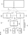
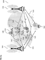
- the system 100 can include an evolved universal terrestrial radio access network (“EUTRAN”) 102, an evolved packet core (“EPC”) 108, and a packet data network (“PDN”) 101, where the EUTRAN 102 and EPC 108 provide communication between a user equipment 104 and the PDN 101.
- the EUTRAN 102 can include a plurality of evolved node B's (“eNodeB” or “ENODEB” or “enodeb” or “eNB”) or base stations 106 (a, b, c) (as shown in FIG. 1b ) that provide communication capabilities to a plurality of user equipment 104(a, b, c).
- the user equipment 104 can be a mobile telephone, a smartphone, a tablet, a personal computer, a personal digital assistant ("PDA"), a server, a data terminal, and/or any other type of user equipment, and/or any combination thereof.
- the user equipment 104 can connect to the EPC 108 and eventually, the PDN 101, via any eNodeB 106.
- the user equipment 104 can connect to the nearest, in terms of distance, eNodeB 106.
- the EUTRAN 102 and EPC 108 work together to provide connectivity, mobility and services for the user equipment 104.
- FIG. 1b illustrates further detail of the network 100 shown in FIG. 1a .
- the EUTRAN 102 includes a plurality of eNodeBs 106, also known as cell sites.
- the eNodeBs 106 provides radio functions and performs key control functions including scheduling of air link resources or radio resource management, active mode mobility or handover, and admission control for services.
- the eNodeBs 106 are responsible for selecting which mobility management entities (MMEs, as shown in FIG. 1c ) will serve the user equipment 104 and for protocol features like header compression and encryption.
- MMEs mobility management entities
- the eNodeBs 106 that make up an EUTRAN 102 collaborate with one another for radio resource management and handover.
- Air interface 122 also known as "LTE-Uu" interface.
- the air interface 122 provides communication between user equipment 104b and the eNodeB 106a.
- the air interface 122 uses Orthogonal Frequency Division Multiple Access (“OFDMA”) and Single Carrier Frequency Division Multiple Access (“SC-FDMA”), an OFDMA variant, on the downlink and uplink respectively.
- OFDMA allows use of multiple known antenna techniques, such as, Multiple Input Multiple Output (“MIMO").
- MIMO Multiple Input Multiple Output
- the air interface 122 uses various protocols, which include a radio resource control (“RRC”) for signaling between the user equipment 104 and eNodeB 106 and non-access stratum (“NAS”) for signaling between the user equipment 104 and MME (as shown in FIG. 1c ).
- RRC radio resource control
- NAS non-access stratum
- user traffic is transferred between the user equipment 104 and eNodeB 106. Both signaling and traffic in the system 100 are carried by physical layer (“PHY”) channels.
- PHY physical layer
- eNodeBs 106 can be interconnected with one another using an X2 interface 130(a, b, c).
- X2 interface 130a provides interconnection between eNodeB 106a and eNodeB106b
- X2 interface 130b provides interconnection between eNodeB 106a and eNodeB 106c
- X2 interface 130c provides interconnection between eNodeB 106b and eNodeB 106c.
- the X2 interface can be established between two eNodeBs in order to provide an exchange of signals, which can include a load- or interference-related information as well as handover-related information.
- the eNodeBs 106 communicate with the evolved packet core 108 via an S1 interface 124(a, b, c).
- the S1 interface 124 can be split into two interfaces: one for the control plane (shown as control plane interface (S1-MME interface) 128 in FIG. 1c ) and the other for the user plane (shown as user plane interface (S1-U interface) 125 in FIG. 1c ).
- the EPC 108 establishes and enforces Quality of Service ("QoS") for user services and allows user equipment 104 to maintain a consistent internet protocol (“IP”) address while moving. It should be noted that each node in the network 100 has its own IP address.
- the EPC 108 is designed to interwork with legacy wireless networks.
- the EPC 108 is also designed to separate control plane (i.e., signaling) and user plane (i.e., traffic) in the core network architecture, which allows more flexibility in implementation, and independent scalability of the control and user data functions.
- the EPC 108 architecture is dedicated to packet data and is shown in more detail in FIG. 1c .
- the EPC 108 includes a serving gateway (S-GW) 110, a PDN gateway (P-GW) 112, a mobility management entity (“MME”) 114, a home subscriber server (“HSS”) 116 (a subscriber database for the EPC 108), and a policy control and charging rules function (“PCRF”) 118.
- S-GW serving gateway
- P-GW PDN gateway
- MME mobility management entity
- HSS home subscriber server
- PCRF policy control and charging rules function
- the S-GW 110 functions as an IP packet data router and is the user equipment's bearer path anchor in the EPC 108. Thus, as the user equipment moves from one eNodeB 106 to another during mobility operations, the S-GW 110 remains the same and the bearer path towards the EUTRAN 102 is switched to talk to the new eNodeB 106 serving the user equipment 104. If the user equipment 104 moves to the domain of another S-GW 110, the MME 114 will transfer all of the user equipment's bearer paths to the new S-GW.
- the S-GW 110 establishes bearer paths for the user equipment to one or more P-GWs 112. If downstream data are received for an idle user equipment, the S-GW 110 buffers the downstream packets and requests the MME 114 to locate and reestablish the bearer paths to and through the EUTRAN 102.
- the P-GW 112 is the gateway between the EPC 108 (and the user equipment 104 and the EUTRAN 102) and PDN 101 (shown in FIG. 1a ).
- the P-GW 112 functions as a router for user traffic as well as performs functions on behalf of the user equipment. These include IP address allocation for the user equipment, packet filtering of downstream user traffic to ensure it is placed on the appropriate bearer path, enforcement of downstream QoS, including data rate.
- the subscriber can use services on PDNs served by different P-GWs, in which case the user equipment has at least one bearer path established to each P-GW 112.
- the bearer path from the P-GW 112 is switched to the new S-GW.
- the MME 114 manages user equipment 104 within the EPC 108, including managing subscriber authentication, maintaining a context for authenticated user equipment 104, establishing data bearer paths in the network for user traffic, and keeping track of the location of idle mobiles that have not detached from the network. For idle user equipment 104 that needs to be reconnected to the access network to receive downstream data, the MME 114 initiates paging to locate the user equipment and re-establishes the bearer paths to and through the EUTRAN 102. MME 114 for a particular user equipment 104 is selected by the eNodeB 106 from which the user equipment 104 initiates system access.
- the MME is typically part of a collection of MMEs in the EPC 108 for the purposes of load sharing and redundancy.
- the MME 114 is responsible for selecting the P-GW 112 and the S-GW 110, which will make up the ends of the data path through the EPC 108.
- the PCRF 118 is responsible for policy control decision-making, as well as for controlling the flow-based charging functionalities in the policy control enforcement function ("PCEF"), which resides in the P-GW 110.
- the PCRF 118 provides the QoS authorization (QoS class identifier (“QCI”) and bit rates) that decides how a certain data flow will be treated in the PCEF and ensures that this is in accordance with the user's subscription profile.
- QCI QoS class identifier
- bit rates bit rates
- the IP services 119 are provided by the PDN 101 (as shown in FIG. 1a ).
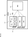
- FIG. 1d illustrates an exemplary structure of eNodeB 106.
- the eNodeB 106 can include at least one remote radio head (“RRH”) 132 (typically, there can be three RRH 132) and a baseband unit (“BBU”) 134.
- the RRH 132 can be connected to antennas 136.
- the RRH 132 and the BBU 134 can be connected using an optical interface that is compliant with common public radio interface (“CPRI") 142 standard specification.
- CPRI common public radio interface
- the operation of the eNodeB 106 can be characterized using the following standard parameters (and specifications): radio frequency band (Band4, Band9, Band17), bandwidth (5, 10, 15, 20 MHz), access scheme (downlink: OFDMA; uplink: SC-OFDMA), antenna technology (downlink: 2x2 MIMO; uplink: 1x2 single input multiple output (“SIMO")), number of sectors (6 maximum), maximum transmission power (60W), maximum transmission rate (downlink: 150 Mb/s; uplink: 50 Mb/s), S1/X2 interface (1000Base-SX, 1000Base-T), and mobile environment (up to 350 km/h).
- radio frequency band Band4, Band9, Band17
- bandwidth 5, 10, 15, 20 MHz
- access scheme downlink: OFDMA; uplink: SC-OFDMA
- antenna technology downlink: 2x2 MIMO; uplink: 1x2 single input multiple output (“SIMO")
- number of sectors (6 maximum), maximum transmission power (60W), maximum transmission rate (downlink: 150 Mb/s;
- the BBU 134 can be responsible for digital baseband signal processing, termination of S1 line, termination of X2 line, call processing and monitoring control processing. IP packets that are received from the EPC 108 (not shown in FIG. 1d ) can be modulated into digital baseband signals and transmitted to the RRH 132. Conversely, the digital baseband signals received from the RRH 132 can be demodulated into IP packets for transmission to EPC 108.
- the RRH 132 can transmit and receive wireless signals using antennas 136.
- the RRH 132 can convert (using converter (“CONV") 140) digital baseband signals from the BBU 134 into radio frequency ("RF") signals and power amplify (using amplifier (“AMP”) 138) them for transmission to user equipment 104 (not shown in FIG. 1d ).
- the RF signals that are received from user equipment 104 are amplified (using AMP 138) and converted (using CONV 140) to digital baseband signals for transmission to the BBU 134.
- FIG. 2 illustrates an additional detail of an exemplary eNodeB 106.
- the eNodeB 106 includes a plurality of layers: LTE layer 1 202, LTE layer 2 204, and LTE layer 3 206.
- the LTE layer 1 includes a physical layer ("PHY”).
- the LTE layer 2 includes a medium access control (“MAC”), a radio link control (“RLC”), a packet data convergence protocol (“PDCP”).
- the LTE layer 3 includes various functions and protocols, including a radio resource control (“RRC”), a dynamic resource allocation, eNodeB measurement configuration and provision, a radio admission control, a connection mobility control, and radio resource management (“RRM").
- RRC radio resource control
- RRM radio resource management
- the RLC protocol is an automatic repeat request ("ARQ") fragmentation protocol used over a cellular air interface.
- the RRC protocol handles control plane signaling of LTE layer 3 between the user equipment and the EUTRAN.
- RRC includes functions for connection establishment and release, broadcast of system information, radio bearer establishment/reconfiguration and release, RRC connection mobility procedures, paging notification and release, and outer loop power control.
- the PDCP performs IP header compression and decompression, transfer of user data and maintenance of sequence numbers for Radio Bearers.
- the BBU 134 shown in FIG. 1d , can include LTE layers L1-L3.
- the eNodeB 106 is radio resource management, which includes scheduling of both uplink and downlink air interface resources for user equipment 104, control of bearer resources, and admission control.
- the eNodeB 106 as an agent for the EPC 108, is responsible for the transfer of paging messages that are used to locate mobiles when they are idle.
- the eNodeB 106 also communicates common control channel information over the air, header compression, encryption and decryption of the user data sent over the air, and establishing handover reporting and triggering criteria.
- the eNodeB 106 can collaborate with other eNodeB 106 over the X2 interface for the purposes of handover and interference management.
- the eNodeBs 106 communicate with the EPC's MME via the S1-MME interface and to the S-GW with the S1-U interface. Further, the eNodeB 106 exchanges user data with the S-GW over the S1-U interface.
- the eNodeB 106 and the EPC 108 have a many-to-many relationship to support load sharing and redundancy among MMEs and S-GWs.
- the eNodeB 106 selects an MME from a group of MMEs so the load can be shared by multiple MMEs to avoid congestion.
- FIG. 3 illustrates an exemplary system 300, according to some implementations of the current subject matter.
- the system 300 can be implemented as a centralized cloud radio access network ("C-RAN").
- the system 300 can include at least one intelligent remote radio head (“iRRH”) unit 302 and an intelligent baseband unit (“iBBU) 304.
- the iRRH 302 and iBBU 304 can be connected using Ethernet fronthaul ("FH") communication 306 and the iBBU 304 can be connected to the EPC 108 using backhaul ("BH”) communication 308.
- the user equipment 104 (not shown in FIG. 3 ) can communicate with the iRRH 302.
- the iRRH 302 can include the power amplifier (“PA”) module 312, the radio frequency (“RF") module 314, LTE layer L1 (or PHY layer) 316, and a portion 318 of the LTE layer L2.
- the portion 318 of the LTE layer L2 can include the MAC layer and can further include some functionalities/protocols associated with RLC and PDCP, as will be discussed below.
- the iBBU 304 can be a centralized unit that can communicate with a plurality of iRRH and can include LTE layer L3 322 (e.g., RRC, RRM, etc.) and can also include a portion 320 of the LTE layer L2.
- the portion 320 can include various functionalities/protocols associated with PDCP.
- the system 300 can be configured to split functionalities/protocols associated with PDCP between iRRH 302 and the iBBU 304.
- the system 300 can implement carrier aggregation (“CA”) and coordinated multipoint (“CoMP”) transmission features.
- CA carrier aggregation
- CoMP coordinated multipoint
- the CA and CoMP features have been discussed in the 3GPP standards for 4G LTE-Advanced, Releases 10 and 11, respectively. Both features are designed to increase data throughput rate and designed to work with 4G LTE-Advanced. The following is a brief summary of each of these features.
- the CA or channel aggregation enables multiple LTE carriers to be used together to provide high data rates that are required for 4G LTE-Advanced. These channels or carriers can be in contiguous elements of the spectrum, or they may be in different bands.
- the carriers can be aggregated using contiguous intra-band carrier aggregation, non-contiguous intra-band carrier aggregation, and inter-band non-contiguous carrier aggregation.
- contiguous intra-band carrier aggregation carriers are adjacent to one another and aggregated channel can be considered by a user equipment as a single enlarged channel from a radio frequency ("RF") viewpoint and only one transceiver is required within the user equipment (usually, more transceivers are required where the channels are not adjacent).
- RF radio frequency
- each carrier can be referred to as a component carrier.
- component carriers There exist two categories of component carriers: a primary component carrier (i.e., main carrier in any group; there are a primary downlink carrier and an associated uplink primary component carrier), and a secondary component carrier (there are one or more secondary component carriers). Association between downlink primary and corresponding uplink primary component carriers is cell specific.
- Cross-carrier scheduling can be achieved individually via RRC signaling on a per component carrier basis or a per user equipment basis.
- the downlink scheduling assignments can be achieved on a per carrier basis.
- an association can be created between one downlink component carrier and an uplink component carrier.
- the physical downlink shared channel (“PDSCH”) on the downlink or the physical uplink shared channel (“PUSCH”) on the uplink is transmitted on an associate component carrier other than the physical downlink control channel (“PDCCH")
- the carrier indicator in the PDCCH provides the information about the component carrier used for the PDSCH or PUSCH.
- the PDSCH is the main data bearing channel allocated to users on a dynamic basis and that carries data in transport blocks (“TB") that correspond to a MAC packet data unit (“PDU”), which are passed from the MAC layer to the PHY layer once per transmission time interval (“TTI”) (i.e., 1 ms).
- TTI transmission time interval
- the PUSCH is a channel that carries user data and any control information necessary to decode information such as transport format indicators and MIMO parameters.
- the PDCCH is a channel that carries resource assignment for user equipments, which are contained in a downlink control information ("DCI") message.
- DCI downlink control information
- cells e.g., F1 and F2 cells
- F1 and F2 cells can be co-located and overlaid, thereby providing nearly the same coverage. Both layers provide sufficient coverage and mobility can be supported on both layers.
- cells F1 and F2 can be co-located and overlaid, however, F2 cells have smaller coverage due to larger path losses, where only F1 cells provide sufficient coverage and F2 cells are used to improve throughput.
- mobility is performed based on F1 cells coverage.
- F1 and F2 cells are co-located and overlaid, however, F2 cells have smaller coverage due to larger path losses, where only F1 cells provide sufficient coverage and F2 cells are used to improve throughput.
- F1 cells provide macro coverage and F2 cells' remote radio heads are used to improve throughput at hot spots, where mobility is again performed based on F1 cells coverage.
- frequency selective repeaters are deployed so that coverage is extended for one of the carrier frequencies. It is expected that F1 and F2 cells of the same eNodeB can be aggregated where coverage overlaps.
- the CoMP transmission feature is used to send and receive data to and from a user equipment from several points to ensure the optimum performance is achieved even at cell edges.
- CoMP enables dynamic coordination of transmission and reception over a variety of different base stations to improve overall quality for the user as well as improve utilization of the network.
- CoMP further requires close coordination between a number of geographically separated eNodeBs to provide joint scheduling and transmissions, joint processing of received signals, thereby allowing a user equipment at the edge of a cell to be served by two or more eNodeBs so as to improve signal reception/transmission and increase throughput.
- the first scenario involves a homogeneous network with intra-site CoMP.
- the second scenario also involves a homogeneous network but with high transmission power RRHs.
- the third scenario involves a heterogeneous network with low power RRHs within a macro cell coverage, where transmission/reception points created by the RRHs have different cell identifiers as the macro cell.
- the fourth scenario involves a heterogeneous network with low power RRHs within a macro cell coverage, where transmission/reception points created by the RRHs have the same cell identifiers as the macro cell.
- the CoMP feature uses the following three scheme: coordinated scheduling/beamforming ("CS/CB”), joint processing (“JP”), and dynamic point selection (“DPS”).
- CS/CB scheme coordinates steering of beams formed by different transmission points serving different user equipments.
- a user equipment can be semi-statically served by only one transmission point and data does not need to be passed around from transmission point to transmission point.
- the JP scheme involves simultaneous data transmission from multiple transmission points to a single user equipment or multiple user equipments in a time-frequency resource.
- JT scheme requires different transmission points to be completely synchronized in terms of the timing, TB format, PRB allocation and reference signals when transmitting data to a particular user equipment. The user equipment need not be aware that the transmission is coming from multiple transmission points.
- the DPS scheme (a variant of the JT scheme) involves data transmission from one transmission point in a time-frequency resource, where the transmission point may change from one subframe to another.
- FIG. 4a illustrates an exemplary system 400, according to some implementations of the current subject matter.
- the system 400 can be configured to implement 4G LTE-Advanced features, including carrier aggregation feature.
- the system 400 can include an intelligent baseband unit ("iBBU") 402, a primary cell (“Pcell”) intelligent remote radio head 404 and one or more secondary cells (“Scell”) intelligent remote radio heads 406.
- iBBU intelligent baseband unit
- Pcell primary cell
- Scell secondary cells
- the Pcell is the serving cell where the UE has an RRC connection with the radio access network.
- Pcell can only be changed through a successful execution of a handover procedure.
- Scell is a secondary cell that can be added/removed from the configured cells list when the UE moves into/out of its coverage area.
- the configuration of a Scell is done by RRC based on mobility measurement events triggered in the UE and sent to RRC.].
- each iRRH 404 and 406 can both include the LTE layer 1 (i.e., the PHY layer) and have LTE layer 2 (i.e., MAC, PDCP, RLC) split among themselves as well as iBBU 402.
- the iRRH 404 can include a PHY layer 412, a MAC layer 414, a scheduler-Pcell component 416, a master RLC component 418, a RLC status component 420, a PDCP-security component 422, and a BSR component 424.
- the iRRH 406 can include a PHY layer 411, a MAC layer 413, a scheduler-Scell component 415, a slave RLC component 419, a RLC status component 421, a PDCP-security component 423, and a BSR component 425.
- the iBBU 402 can include a buffer management component 432, a PDCP-SN component 434, a PDCP-RoHC component 436, a VAS component 438, an RRC component 440, and a GTP component 442.
- the buffer management component 432 can implement use of buffer occupancy reports that can be received from the iRRH's to control flow of user data to the Pcell and/or Scell in order to enable in sequence delivery of the data to the user equipment.
- the PDCP-SN component 434 can perform sequence numbering of the PDCP service data units ("PDCP SDUs").
- the PDCP robust header compression (“PDCP-RoHC”) component 436 can perform IP header compression for voice-over-LTE service flows.
- the value added services (“VAS”) component 438 can provide application intelligence in the eNodeB by performing shallow packet inspection and deep packet inspection of data flows. This component can also determine how a particular data flow can be treated.
- a shallow packet inspection can be performed by inspecting one or more headers of the data packet to determine information associated with the data packet. For example, the shallow packet inspection can inspect an IP header of the data packet in order to determine the source IP address of the data packet. In some implementations, based on the results of the shallow packet inspection, a deep packet inspection (“DPI”) can be performed by examining other layers of the data packet. In some implementations, the payload of a data packet can be inspected to determine what resource blocks should be assigned to the data packet.
- DPI deep packet inspection
- the iRRH 404 and the iRRH 406 can communicate with one another via an inter-iRRH interface, which can be a direct connection 452, or a connection that can be shared with a fronthaul connection 458.
- the iRRH 404 can communicate with the iBBU 402 using the fronthaul ("FH") connection 458 and the iRRH 406 can communicate with the iBBU 402 using FH connection 464.
- FH fronthaul
- the iBBU 402 can provide a centralized remote radio resource control ("RRC") using RRC component 440, thereby eliminating a need for a long-delay inter-RRC coordination and providing an ability to configure LTE layer 2 in iRRH 404 and 406.
- RRC remote radio resource control
- This capability can be implemented as part of the coordinated multipoint transmission feature, as discussed below.
- the functionalities associated PDCP protocol can be split among the iBBU 402, the iRRH 404, and the iRRH 406.
- the PDCP-ROHC 436 (where ROHC refers to robust header compression protocol that is used to compress packets) and the PDCP-SN 434 (where SN refers to sequence numbering) together with buffer management component 432 in iBBU 402 can be referred to as PDPC-upper, and PDCP-security 422, 423 in iRRH 404, 406, respectively, can be referred to as PDCP-lower.
- the PDCP functionalities can be centralized to handle the ROHC and sequence numbering functions by the iBBU 402, and ciphering functions by the iRRH (which refer to known functionalities of the PDPC).
- the PDCP-upper in iBBU 402 can also handle coordination of data flows to the schedulers in the iRRHs.
- flow control between iBBU 402 and iRRH 406 can be provided.
- the flow control can depend on an estimated data rate for the bearer.
- the PDCP-upper can send compressed and numbered packets to Pcell iRRH 404 and Scell iRRH 406 in proportion based on buffer occupancy level and estimated data rate from the reports provided by PDCP-lower.
- the PDCP-lower can generate a report of a buffer occupancy level. This report can be generated periodically, upon request, automatically, manually, and/or on for any period of time.
- the PDCP-upper can estimate a buffer draining rate based on consecutive buffer occupancy reports (e.g., two reports), a time that elapsed between the reports and the additional data that was sent to the buffer between the reports.
- the iBBU 402 can include a buffer management function 432 to support the in-sequenced delivery of PDCP packet data units ("PDCP PDU") and support value added services ("VAS") multi-queue implementation for the default bearer.
- the buffer management function 432 can detect buffer stalling in the Scell 406 and trigger a redirection of the staled PDCP PDU packets to the Pcell 404.
- PDCP-lower can detect outdated packets and discard them from its buffer.
- the in-sequenced delivery of PDCP PDUs can refer to a requirement for data flow transmitted in RLC acknowledged and unacknowledged modes.
- VAS multi-queue implementation can enable prioritization of data flows within the default bearer.
- the detection of buffer stalling can be based on an estimated buffer drain rate that can be derived from the buffer occupancy reports received from the PDCP-lower.
- the PDCP-upper can tag each packet data unit with time-to-live information (which can refer to an amount of time before a data packet expires). Then, the PDCP-lower can remove the packet from its buffer when the time-to-live timer for that packet expires and inform the PDCP-upper of the deleted packet's number. The PDCP-upper can decide whether to resend the deleted packet to the same PDCP-lower and/or redirect the deleted packet to a PDCP-lower of another iRRH. The discarding of packets can be performed on the Pcell and/or the Scell and the packets can be redirected toward the Pcell and/or the Scell.
- time-to-live information which can refer to an amount of time before a data packet expires.
- the RLC protocol handling can be split between iRRH 404 and iRRH 406, where the iRRH 404 can include a master RLC component 418 and the iRRH 406 can include a slave RLC component 419.
- the master RLC component 418 can allocate an RLC PDU sequence number to the slave RLC component 419, thereby centralizing RLC PDU sequence numbering process.
- each RLC entity can maintain a list of unacknowledged PDUs that it has transmitted and thus, handle the ARQ procedures for only those unacknowledged PDUs that it has transmitted.
- an RLC ARQ status PDU which can be sent from a user equipment at a rate of once very few 10's of a millisecond, can be shared between the two RLC entities over the inter-iRRH interface, i.e., the direct connection 452 and/or a connection shared with fronthaul 458.
- the physical connection for this inter-iRRH interface can either be direct and/or through a L2 Ethernet switch.
- the above inter-iRRH interface can leverage industry standard stream control transport protocol ("SCTP") over IP.
- SCTP industry standard stream control transport protocol
- the application layer information exchange can be based on an inter-process communication protocols.
- the inter-iRRH interface 452 can provide a low latency interface for sharing of the RLC status information PDUs as well as any other information between iRRHs 404 and 406.
- Channel state information (“CSI"), acknowledgement/non-acknowledgement (“ACK/NACK”) signaling, precoding matrix indicator (“PMI”), and rank indicator (“RI”) that are received by the Pcell iRRH 404 can be forwarded over the inter-iRRH interface 452 for sharing with an Scell scheduler 415 via the fronthaul or direct gigabit Ethernet (“GE”) connection.
- This information can be available to the Scell scheduler on the same sub-frame that it was sent in order not to incur any impact the H-ARQ RTT, which can be targeted to be 8ms.
- the Scell scheduler can also accommodate longer delay in obtaining the H-ARQ feedback and can impact H-ARQ round trip time on the Scell.
- the inter-iRRH interface 452 can be used by the Scell iRRH 406 to inform the Pcell iRRH 404 which PUCCH resource to expect the arrival of the H-ARQ ACK/NACK feedback for a packet sent on the Scell (where the allocation of PUCCH resources is defined in the 3GPP Standards for 4G LTE).
- the scheduler can be designed to determine which user equipment to schedule 2ms in advance of when the data is transmitted over the air.
- the H-ARQ ACK/NACK can be sent from the user equipment 4ms after the data has been received.
- an exemplary one-way latency for the inter-iRRH interface 452 might not be more than 4ms.
- the above is provided as an illustrative non-limiting, exemplary implementation of the current subject matter system. It should be further understood that the current subject matter system is not limited to specific data scheduling parameters and/or particular latency associated with transmission of data, and can be designed using any scheduling, latency and/or any other parameters.
- the inter-iRRH transport 456 can be shared with the fronthaul and switched at the iBBU 402 and/or a physical direct connection 452 between the iRRHs 404, 406 using a gigabit Ethernet interface.
- the fronthaul latency can be based on a very low latency transport such as in the case when the iBBU 402 and the iRRHs 404 and/or 406 are collocated and/or when based on LOS wireless transport such as MW, mmWave, FSO, when the iRRH's are geographically separated.
- the current subject matter system can be configured to implement 4G LTE-Advanced features, including coordinated multipoint transmission (“CoMP") feature.
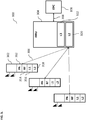
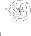
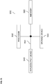
- FIGS. 4b-c illustrate exemplary known dynamic point selection (“DPS") ( FIG. 4b ) and coordinated scheduling/beamforming (“CS/CB”) ( FIG. 4c ) schemes that can be implemented as part of the CoMP feature.
- the DPS scheme can refer to a scheme where the transmission point is varied according to changes in channel and interference conditions.
- the CS/CB scheme can allow coordination of scheduling decisions of neighboring points to reduce interference.
- These schemes can include point blanking/muting, i.e., whereby one or more transmission points can be turned off in order to decrease interference. These schemes can reduce interference and improve the LTE cell-edge performance.
- the user equipment can be scheduled to receive data from two points while a third point is muted and/or the user equipment can be scheduled to receive data only from one point where the other one or more points coordinate scheduling and/or are muted to reduce interference.
- FIG. 4b illustrates an exemplary implementation of the DPS scheme.
- a user equipment 479 can be located within a coordination area 472 of two points 473 and 477, where each has cell areas 471 and 475, respectively.
- the user equipment 479 can be served by one of the points 473, 477 having better channel conditions.
- FIG. 4c illustrates an exemplary implementation of the CS/CB scheme.
- a user equipment 489 can be located within a coordination area 482 of two points 483 and 487, where each has cell areas 481 and 485, respectively.
- beam forming and scheduling for the user equipment can be coordinated by the network to avoid interference 486 that can be generated by one of the points (e.g., point 487 as shown in FIG. 4c ).
- the operation of the current subject matter system using dynamic point selection scheme can be as follows.
- the user equipment can connect to a serving cell using an RRC connection setup and configured for transmission (e.g., TM10 transmission mode). Once the connection is setup, the uplink connection can remain on the serving cell and can change with the handover procedure.
- RRC can configure initial downlink transmission points ("TP") based on known reference signal received power (“RSRP”) and reference signal received quality (“RSRQ”) measurements, which refer to parameters of a strength/quality of a reference signal (“RS”) of a cell as determined by a user equipment when it moves from cell to cell and performs cell selection/reselection and handover.
- RSRP reference signal received power
- RSRQ reference signal received quality
- the RRC can then configure channel state information reference signal ("CSI-RS") process per transmission point for channel state information (“CSI") reporting, including precoding matrix for physical downlink shared channel (“PMI”), which can be referred to as a measurement set. Then, the RRC can configure enhanced physical downlink control channel (“ePDCCH”) per transmission point, which can be referred as a cooperation set. Then, each CoMP transmission point can perform its own scheduling and send an allocation over ePDCCH, thereby providing resource and link adaptation information.
- the current transmission point serving the user equipment can decode physical uplink control channel information sent by user equipment to the serving cell to extract HARQ and CSI feedback information. Based on that information, the current transmission point can determine the resource allocation for the user equipment.
- the iBBU can preposition data at all transmission points in the cooperation set for fast switching of CoMP transmission points. Then, only the RLC context can be transferred from a previous transmission point to the current transmission point during transmission point switching. Based on the CSI feedback, the current transmission can inform RRC/RRM components in the iBBU to allow these components to make decisions on transmission point switching and transmission point addition/dropping from the cooperation and measurement sets as well as serving cell change (e.g., during handover). Further, the RRC/RRM components can then select an active transmission point based on a load level of each transmission point in the cooperation set as well as based on the CSI.
- the operation of the current subject matter system using the coordinated scheduling/beamforming scheme can be as follows.
- fractional frequency reuse (“FFR") mechanism can be activated to provide a blanking mechanism and/or to lower the power of physical resource blocks ("PRBs") in scheduling coordination with the serving transmission point (as discussed in 3GGP standards for 4G LTE, and in particular its Release 8 discussing a dynamic inter-cell interference coordination (“ICIC”)).
- PRBs physical resource blocks
- IRC dynamic inter-cell interference coordination
- TDD time division duplex
- UL SRS uplink sounding reference signal
- Coordinated beam forming can be achieved using semi-static time and spatial domain coordination between the transmission points in the cooperation set.
- the PMI feedback for each CSI-RS process can be configured.
- the PUCCH can be decoded at each transmission point for channel state information reported by the user equipment.
- the coordinated beam forming can be also achieved using semi-static time and spatial domain coordination between the transmission points in the cooperation set and based on channel state information reports at each transmission point.
- the inter-iRRH one-way latency may be less than 200ms, which can allow for transmission point switching with a gap of two transmission time intervals ("TTI"). Other values one-way latencies are possible and may or may not be noticeable.
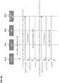
- FIGS. 5a-8d provide a discussion of exemplary call flow procedures using the current subject matter system, including the RRC procedures, such as, an inter-eNodeB handover procedure (as shown in FIGS. 5a-5d ), an intra-eNodeB handover procedure (as shown in FIGS. 6a-6c ), an RRC connection establishment procedure (as shown in FIGS. 7a-7h ), and an RRC connection re-establishment procedure (as shown in FIGS. 8a-8d ).
- the procedures shown in FIGS. 5a-8d are provided for exemplary, non-limiting and/or illustrative purposes. It is not intended that the current subject matter system be limited to the shown call flow procedures. Other procedures and/or variations of the illustrated procedures can be used by the current subject matter system.
- the current subject matter system can significantly reduce latency associated with communications in the LTE systems.
- FIGS. 5a-5d illustrate an exemplary inter-eNodeB handover procedures in the control plane, according to some implementations of the current subject matter.
- FIG. 5a illustrates an exemplary system 500 that can include an iBBU 504 and an iBBU 506 that can communicate with an evolved packet core ("EPC") 502 using S1 connections 531, 533, respectively.
- the iBBUs 504 and 506 can communicate with one another using an X2 connection 535.
- One of the iBBUs 504, 506 can be a source (i.e., from where a communication can originate) and the other can be a target (i.e., a recipient of the communication).
- the system 500 can also include a plurality of iRRHs 508, 510, 512, and 514.
- the iRRHs can be connected with to their respective iBBUs via fronthaul ("FH") connections.
- FH fronthaul
- the iRRH 508 can be connected to the iBBU 504 via FH connection 541;
- the iRRH 510 can be connected to the iBBU 504 via FH connection 543
- the iRRH 512 can be connected to the iBBU 506 via FH connection 545;
- iRRH 514 can be connected to the iBBU 506 via FH connection 547.
- a plurality of user equipments 516, 518, 520, and 522 can communicate over-the-air with the iRRH 508, 510, 512, and 514, respectively.
- the system 500 can allow for various handover scenarios, which can include a macro-to-macro scenario, micro-to-micro scenario, micro-to-macro scenario, and macro-to-micro scenario.
- the user equipment 520 can directly communicate with the iBBU 506.
- the iBBUs can be centralized, which can cause the X2 interface 535 to have zero latency.
- the macro iRRH can be collocated with the iBBU and thus, the two can be connected using a very low latency FH connection, thereby making an impact on HO performance caused by the FH latency negligible.
- the micro-to-micro scenario can involve a communication between two iRRH 510, 512.
- both the source and the target cells i.e., iBBUs 504, 506 can have high-latency FH connections.
- the micro-to-macro scenario can involve a communication between user equipment 516 and iBBU 506.
- any communications between the user equipment 516 and the source micro cell can involve at least one high-latency FH communication.
- the macro-to-micro scenario can involve communication between user equipment 522 and iRRH 514.
- any communications between the user equipment 522 and the target micro cell can involve at least one high-latency FH communication.
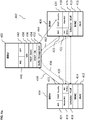
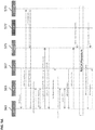
- FIG. 5b illustrates exemplary handover procedures for a source eNodeB, according to some implementations of the current subject matter.
- the commands or messages exchanged during the handover procedures are between a user equipment RRC 551, a radio resource management module 553 (located at an eNodeB), a eNodeB's RRC module (RRC_Cell) 555, an S1 application interface (S1AP (located at eNodeB)) 557, a PDCP layer (located at eNodeB) 559, and GPRS Tunneling Protocol ("GTP”) Manager (GTP Mgr (located at eNodeB)) 561.
- RRC 551 radio resource management module
- RRC_Cell Radio Resource Control module
- S1AP located at eNodeB
- S1AP located at eNodeB
- PDCP layer located at eNodeB
- GTP Mgr GPRS Tunneling Protocol
- This message can be directed from the source eNodeB to the target eNodeB and can traverse the S1/X2 interface(s) with an equivalent of two links, one for each eNodeB.
- a handover command (to user equipment) (“Handover Command (to UE)" message can be originated from the target eNodeB and can also traverse the S1/X2 interface with an equivalent of two links, one for each eNodeB.
- the "eNB Status Transfer Request,” “eNB Transfer Response” and “eNB Status Transfer” messages are exchanged with the RRC-UE 55 to provide the source eNodeB status. Once that information is provided, a known “UE Context Release Procedure” can be initiated with “UE Context Release Command” and can be completed with “UE Context Release Complete” messages.
- the Meas Result and Handover Command (to UE) messages can go over a very low latency the FH connection, thereby making the impact of transmission of these messages negligible.
- the Handover Required message going over the S1/X2 interface might not add more latency to the handover procedure when compared to the handover procedure based on the distributed deployment of the eNodeB.
- the FH connection latency can affect the connection, with the latency on the S1 or X2 interface being insignificant.
- the FH latency can be more than offset by the zero latency on the S1/X2. A reduction equivalent to two links can be achieved.
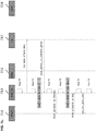
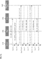
- FIG. 5c illustrates exemplary handover procedures for a target eNodeB, according to some implementations of the current subject matter.
- the commands or messages exchanged during the handover procedures are between a user equipment RRC 563, a radio resource management module 565 (located at the target eNodeB), S1 application interface (S1AP (located at the target eNodeB)) 567, radio link control/MAC layer (located at the target eNodeB) 569, a PDCP layer (located at the target eNodeB) 571, and GTP Manager (GTP Mgr (located at eNodeB)) 573.
- RRC 563 a radio resource management module 565 (located at the target eNodeB), S1 application interface (S1AP (located at the target eNodeB)) 567, radio link control/MAC layer (located at the target eNodeB) 569, a PDCP layer (located at the target eNodeB
- the current call flow can have three pairs of request/response messages traversing the fronthaul before the handover request acknowledge message is sent back to the source eNodeB.
- These messages can include: "CRNTI Request/CRNTI Response,” "RLC/MAC Config/RLC/MAC Config response”, and "PDCP Config/PDCP Config Response," which can be layer 1 and/or layer 2 configuration messages.
- This part of the call flow can be considered as the handover preparation phase. Similar to FIG.
- target eNodeB status transfer information messages can be exchanged with the RRC-UE 563 and subsequent to the exchange of this information, a known random access channel ("RACH") procedure can be performed.
- RACH random access channel
- these pairs of three layer 1 and/or layer 2 configuration messages can be combined into one layer 2 "Config Request”/"L2 Config Response” pair. Thus, only two messages would have to traverse the fronthaul during this handover preparation phase.
- two additional messages can traverse the fronthaul before the target eNodeB starts sending data to the user equipment.
- These can include: "RRCConnectionReconfigurationComplete” and "Send DL Data to UE.” These can also be optimized by giving the PDCP entity in the iRRH an intelligence to know when the "RRCConnectionReconfigurationComplete" is received and start sending data without being instructed by the RRC component. In some implementations, both messages can be eliminated from gating the start of data transfer.
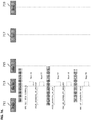
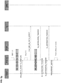
- FIG. 5d illustrates an exemplary optimized call flow for the S1-based handover in the target eNodeB, according to some implementations of the current subject matter.
- FIG. 5d is similar to FIG. 5c and includes some of the same components which are used to exchange commands or messages (i.e., the user equipment RRC 563, a radio resource management module 565, S1AP 567, and GTP Manager 573).
- the radio link control/MAC layer and a PDCP layer have been combined into a single component 575 and a VAS component 577 has been added.
- the target eNodeB is a macro cell and its iRRH is co-located with the iBBU, then there can be no penalty on the handover procedure due to the low latency fronthaul.
- varying degrees of latency on the fronthaul can affect inter eNodeB handover performance .
- FIGS. 6a-6d illustrate an exemplary intra-eNodeB handover procedures in the control plane, according to some implementations of the current subject matter.
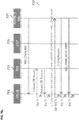
- FIG. 6a illustrates an exemplary system 600 that can include an iBBU 604 that can communicate with an evolved packet core ("EPC") 602 using an S1 connection 631.
- the system 600 can also include iRRHs 608 and 610.
- the iRRHs 608, 610 can be connected with to the iBBU 604 via fronthaul ("FH") connections.
- FH fronthaul
- the iRRH 608 can be connected to the iBBU 604 via FH connection 641; the iRRH 610 can be connected to the iBBU 604 via FH connection 643.
- a plurality of user equipments 616, 618, 620, and 622 can communicate over-the-air with the iRRH 608 and 610.
- the system 600 can allow for various handover scenarios, which can include a macro-to-macro scenario, micro-to-micro scenario, micro-to-macro scenario, and macro-to-micro scenario.
- the iBBU 604 in the macro-to-macro scenario, can be centralized (having higher latency on the fronthaul) or a macro iRRH can be collocated with the iBBU 604 (having a low latency on the fronthaul). In this scenario, an impact to handover performance caused by the fronthaul latency can be negligible.
- both source and target cells can have high latency fronthaul connections.
- any handovers involving a micro cell can involve an inter-eNodeB handover with inter-eNodeB control messages traversing the S1 or X2 links with an associated latency impact.
- any communications between user equipment and a source micro cell can involve at least one high latency fronthaul link. Similar to the micro-to-micro scenario, latency can impact any inter-eNodeB handover that can involve inter-eNodeB control messages traversing S1 or X2 links.
- any communications between user equipment and the target micro cell can involve at least one high latency fronthaul link.
- This scenario is also similar to the micro-to-micro and micro-to-macro scenarios.
- the intra-eNodeB handover can be similar to X2 (inter-eNodeB) handover.
- an X2AP module 639 can route messages meant for cells belonging to the same eNodeB.
- FIGS. 6b-c illustrate exemplary call flows for the X2-based handover procedures in the source and the target eNodeB, respectively.
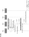
- FIG. 6b illustrates exemplary X2-based handover procedures for a source eNodeB, according to some implementations of the current subject matter.
- the commands or messages exchanged during the handover procedures are between a user equipment RRC 633, a radio resource management module 635 (located at an eNodeB), a eNodeB's RRC module (RRC_Cell) 637, an X2 application interface (X2AP (located at eNodeB)) 639, a PDCP layer (located at eNodeB) 641, and GTP Manager (GTP Mgr (located at eNodeB)) 643.
- RRC 633 a radio resource management module 635 (located at an eNodeB), a eNodeB's RRC module (RRC_Cell) 637, an X2 application interface (X2AP (located at eNodeB)) 639, a PDCP layer (located at eNodeB) 64
- the number of messages traversing the fronthaul can similar to the number of messages traversing the fronthaul in the inter-eNodeB handover procedures, as discussed in FIG. 5b above.
- the source eNodeB is a micro cell
- two additional messages - "Handover Request” and "Handover Request Ack” can traverse the S1/X2 interface with similar link latency in the fronthaul, as discussed above.
- the fronthaul latency can be offset by a zero latency in the intra-eNodeB handover.
- the "Meas Result" and "Handover Command (to UE)" messages can traverse the fronthaul with a low latency, thereby making the latency impact substantially negligible.
- FIG. 6c illustrates exemplary X2-based handover procedures for a target eNodeB, according to some implementations of the current subject matter.
- the commands or messages exchanged during the handover procedures are between a user equipment RRC 645, a radio resource management module (located at the target eNodeB) 647, X2 application interface (X2AP (located at the target eNodeB)) 649, RLC/MAC layer (located at the target eNodeB) 651, a PDCP layer (located at the target eNodeB) 653, and GTP Manager (GTP Mgr (located at eNodeB)) 655.
- RRC 645 a radio resource management module
- X2 application interface X2AP (located at the target eNodeB)
- RLC/MAC layer located at the target eNodeB
- PDCP located at the target eNodeB
- GTP Mgr located at eNodeB
- the X2-based handover procedures for the target eNodeB can be similar to the S1-based handover procedures for the target eNodeB, as discussed above in connection with FIG. 5c . Additionally, if eNodeB is a micro cell, two additional messages - "Handover Request” and "Handover Request Ack" can traverse the S1/X2 interface with similar link latency, as discussed above. As such, there is no increase in intra-eNodeB handover control plane latency due to the fronthaul in the target eNodeB during the handover preparation.
- the "L2 Config Request/L2 Config" messages can traverse the fronthaul with a low latency, thereby making the overall latency impact substantially negligible.
- key performance indicator can include a transmission gap starting at the time the user equipment is informed to switch to a new cell to the time when data can start flowing again.
- DL downlink
- UL uplink
- the DL user-plane performance impact can be based on a number of messages that can traverse the fronthaul thereby gating the start of the downlink data transfer over the air.
- the downlink user-plane performance can be impacted if the data forwarding procedure takes too long and forces the target eNodeB to wait for data to be available to send while the user equipment has already indicated that it is ready to receive.
- FIGS. 5c and 6c illustrate call flow handover procedures during handover execution phase starting when the user equipment has indicated that it has switched over to the target eNodeB using a "RRCConnectionReconfigurationComplete" message. Assuming that the target eNodeB already has data forwarded from the source eNodeB and is ready to send, one additional message "Send DL Data to UE" can be sent to PDCP to start the data transmission to the user equipment.
- the PDCP component in the iRRH can be pre-configured using a "L2 Config Request" message sent during the preparation phase, discussed above, to automatically start sending downlink data and accepting uplink data as soon as the "RRCConnectionReconfigurationComplete” message with the appropriate C-RNTI identity is detected (as shown in FIG. 5d ).
- FIGS. 5b and 6b illustrate exemplary forwarding procedures for the S1-based ( FIG. 5b ) and X2-based ( FIG. 6b ) handovers. If all PDCP functions are located in the iRRH, then there can be three messages that traverse the fronthaul, which are gating the start of the flowing of the forwarded data: "eNodeB Status Transfer Request,” "eNodeB Status Transfer Response” and "Start Data Forwarding" messages.
- PDCP buffers can be co-located in the iBBU along with layer 3 and GTP functions. This optimization can eliminate sending of "Start Data Forwarding" message all the way to PDCP, which can terminate locally.
- the "Status Transfer Request/Response" messages can be also terminated locally in the iBBU.
- the uplink user-plane performance can be affected by the fronthaul latency, through which the traffic must traverse before being forwarded to the EPC over the backhaul link. If the iBBU is centralized at the CO with the S-GW and P-GW, then the S1 latency can be substantially zero. Thus, the increase in latency introduced by the fronthaul can be offset by the reduction in latency from S1.
- the 3GPP Standards can also allow for the buffered UL PDCP SDU received out of sequence in the source eNodeB to be forwarded to the target eNodeB. Even though the buffered data to be forwarded does not gate the first few packets of data sent toward the EPC in the UL, it is important that the data forwarding is carried out in a timely manner to avoid data flow from being interrupted with subsequent packets.
- some PDCP functions e.g. compression and SN numbering
- PDCP buffers can be co-located in the iBBU along with the layer 3 and GTP functions. This can eliminate the need to forward the UL PDCP SDU all the way from the source iRRH to the target iRRH. Instead, the data can be forwarded from the PDCP buffers in the iBBU.
- impact on the uplink user-plane handover performance due to fronthaul latency can be similar to the one for the downlink.
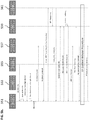
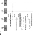
- FIGS.7a-h illustrate details associated with an exemplary RRC connection establishment procedure.
- this procedure can transition a user equipment from an idle state to an active state and can include the following exchange of commands/messages: "RACH Access”, “RRC Connection Establishment Request”, “S1 Setup”, “Initial Security Activation”, “UE Capability Transfer”, and “RRC Connection Reconfiguration” to start the downlink data flow from the EPC.
- the RACH Access procedure can be handled by layer 2 and thus might not involve any messages traversing the fronthaul.
- the S1 interface latency can be assumed to be zero and thus can compensate for some increase in latency due to the front haul.
- FIG. 7a illustrates an exemplary RRC connection establishment procedure 700, according to some implementations of the current subject matter.
- the procedure 700 can involve exchanging or traversing of commands/messages between PDCP component 711, RRC user equipment 713, RRM 715, S1 interface 717 and MAC layer 719.
- the procedure 700 can be initiated by sending a "RRC-CONXN_REQ” message and completed by sending a "RRC_CONXN_SETUP_CMPLT” message from PDPC 711 to RRC user equipment 713. Between these two messages, five additional messages can traverse the fronthaul and thus, contribute to the procedure duration time. These messages can include a pair of PDCP configuration messages - "PDCP_ADDMOD_UE_PROFILE/RSP"; a pair of MAC configuration messages - "DP_CONFIG_CREATE_UE_PROFILE/RSP"; and another RRC message - "RRC_CONXN_SETUP".
- PDCP and MAC messages can be carried out in parallel and/or can be combined into a single layer 2 Config/Rsp message.
- "RRC_CONXN_SETUP” can be combined with the "L2 Config” message, thereby further reducing number of messages traversing fronthaul by one.
- the "L2 Config Rsp” message can also be combined with these two message, thereby further reducing number of messages and total duration time for the procedure 700.
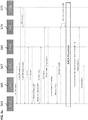
- FIG. 7b illustrates an exemplary optimized RRC connection establishment procedure 710 in accordance with the optimization technique discussed above.
- the combined messages can now be exchanged between RRC-UE 713, RRM 715, S1AP 725, and PDCP/RLC/MAC 727.
- the procedure begins with sending "RRC_CONXN_REQ” message and completes with sending "RRC_CONXN_SETUP_CMPLT” message from PDPC/RLC/MAC 727 to the RRC at the user equipment 713.
- the "Dedicated_RR_Request” and “Dedicated_RR_Response” messages are exchanged between RRC-UE 713 and RRM 715.
- L2 Config Request (which can include “RLC/MAC_Create UE Profile” and “PDPC_ADDMOD UE Profile” messages) and RRC_CONXN_SETUP” can be sent from RRC-UE 713 to PDCP/RLC/MAC 727.
- the "L2 Config Response” message can be sent back to the RRC-UE 713 and followed by the "RRC_CONXN_SETUP_CMPLT” message to complete the RRC connection establishment procedure.
- FIGS. 7c illustrates an exemplary S1 interface setup procedure, according to some implementations of the current subject matter.
- the S1 setup procedure can follow the RRC establishment procedure discussed in connection with FIGS. 7a-b above.
- the S1 setup procedure can include a pair of PDCP configuration messages traversing the fronthaul: "PDCP_ADDMOD_UE_PROFILE" and "PDCP_ADDMOD_UE_RSP" (between PDCP 711 and RRC-UE 713).
- FIG. 7d illustrates an exemplary initial security activation procedure that can follow the S1 interface setup procedure.
- This procedure can include an exchange of the following four messages that traverse the fronthaul: a pair of RRC messages (“RRC_SEC_MOD_CMD” and “RRC_SEC_MOD_COMPLETE” (between PDCP 711 and RRC-UE 713)) and a pair of PDCP configuration messages (“PDCP_ADDMOD_UE_PROFILE” and "PDCP_ADDMOD_UE_RSP” (between PDCP 711 and RRC-UE 713)).
- FIG. 7d also illustrates an exemplary UE capability transfer procedure. This procedure can follow the initial security activation procedure discussed above.
- RRC_UE_CAPABILITY_ENQUIRY and "RRC_UE_CAPABILITY_INFO” (between PDCP 711 and RRC-UE 713)).
- RRC_UE_CAPABILITY_ENQUIRY and "RRC_UE_CAPABILITY_INFO” (between PDCP 711 and RRC-UE 713)).
- the current subject matter system can optimize these three procedures by combining some of the messages that are exchanged between its components into a single message.
- FIG. 7e illustrates an exemplary optimization technique that can reduce the number of messages traversing the fronthaul by a half by combining each "L2 Config" message with an RRC message.
- the optimized procedure can begin with "S1C_NEW_ATTACH_REQ” AND “S1C_INITIAL_UE_CONTEX_SETUP” messages exchanged between the RRC-UE 713 and S1AP 725. Then, a combination of "L2 Config Request” and “RRC_SEC_MOD_CMD” message can be sent from RRC-UE 713 to the PDCP/RLC/MAC 727, where the "L2 Config Request” can include "PDCP_ADDMOD UE PROFILE” message. A "L2 Config Response” and "RRC_SEC_MOD_CMP" messages can follow from PDCP/RLC/MAC 727.
- the next L2 Config message can be also a combination of "L2 Config Request” and “RRC_UE_CAPABILITY_ENQUIRY” messages that are sent from the RRC-UE 713 to the PDCP/RLC/MAC 727, where the "L2 Config Request” can include PDCP_ADDMOD UE Profile” message.
- This combined message can be followed by "L2 Config Response” and "RRC_UE_CAPABILITY INFO” message, thereby completing the optimized procedure.
- the overall delay impact of the fronthaul can be offset by two S1-AP messages ("S1C_NEW_ATTACH_REQ" and "S1C_INITIAL_UE_CONTEXT_SETUP”), which can have a substantially zero transport delay.
- FIGS. 7f-g illustrate exemplary RRC connection reconfiguration and S1 downlink activation procedures, according to some implementations of the current subject matter. These procedures (i.e., exchange of messages that can traverse the fronthaul) can be performed after completion of the S1 setup, initial security activation and UE capability transfer procedures discussed above in connection with FIGS. 7c-e .
- the RRC connection reconfiguration procedure shown in FIG. 7c
- the RRC connection establishment procedure as shown in FIG.
- the PDCP and MAC configuration procedures can occur in parallel and/or can be combined into a single L2 Config/L2 Config Rsp procedure with two messages traversing the fronthaul. Further, similar to the RRC connection establishment procedure (shown in FIG. 7a ), the RRC connection reconfiguration procedure can be optimized by combining the RRC messages with the L2 Config messages, thereby, reducing the two pairs of messages to one.
- the eNodeB can activate the downlink S1 bearer with the EPC to start a data flow.
- the data flow might have to traverse the fronthaul and incur one segment delay before the user equipment state can be considered active.
- FIG. 7h illustrates an exemplary optimized procedures for RRC connection reconfiguration procedures, according to some implementations of the current subject matter.
- the "L2 Config Request” can be combined with the "RRC_CONXN_RECONFIG_REQ” message, where the "L2 Config Request” can include "RLC/MAC_CONFIG_DEDICATED_REQ” and "PDCP_ADDMOD UE Profile” messages, which can be sent to PCP/RLC/MAC 727 from the RRC-UE 713.
- An "L2 Config Response” message followed by "RRC_CONXN_RECONFIG_COMPLETE” message can be received at the RRC-UE 713.
- RRC-UE 713 can send "S1AP_RRC_RB_STATUS_REPORT” message to S1AP 725.
- the S1AP 725 can send a "DL INFORMATION_TRANSFER” message to GTP Manager 733, which can contain information on the downlink.
- the PDCP/RLC/MAC 727 can send the "UL_INFORMATION_TRANSFER” message to GTP Manager 733, which can contain information on the uplink.
- the overall delay impact of the fronthaul can be offset by one S1-AP message, "S1AP_RRC_RB_STATUS REPORT", and the start of the downlink data transfer from the EPC, both of which can have a zero transport delay.
- the RRC connection establishment procedure can be performed in a total of 10 messages being traversed across the fronthaul if the iBBU is co-located with the macro cell and just 6 messages if the iBBU is co-located with the central office.
- the current subject matter system is not limited to the above indicated values.
- FIGS. 8a-d illustrate an exemplary RRC connection re-establishment procedure, according to some implementations of the current subject matter.
- the RRC connection re-establishment procedure can include two stages: an RRC connection re-establishment request stage and an RRC connection re-configuration stage. Each stage's procedures can be similar to the RRC connection establishment procedures shown in FIGS. 7a-g .
- the RRC connection re-establishment procedure can be initiated by sending a "RRC_CONXN_REESTALISH_REQ” message and can be completed by sending "RRC_CONXN_REESTABLISH_CMPLT” message. As shown in FIGS.
- the RRC connection re-establishment procedure can include a pair of PDCP configuration messages ("PDCP_REESTABLISH_REQ” and "PDCP_REESTABLISH_RSP") and a pair of MAC configuration messages (“MAC REESTABISH_REQ” and "MAC_REESTABLISH_RSP”), which can be followed by a pair of RRC messages ("RRC_CONXN_RECONFIG_REQ” and "RRC_CONXN_REESTABLISH” and "RRC_CONXN_REESTABLISH_CMPLT”) between the eNodeB and the UE.
- the PDCP and MAC configuration procedures can occur in parallel and/or can be combined into a single L2 Config/L2 Config Rsp procedure, which can result in one pair of messages traversing the fronthaul.
- FIG. 8d illustrates an exemplary optimized RRC connection reestablishment procedure, according to some implementations of the current subject matter.
- the "RRC_CONXN_REESTABLISH” message can be combined with an "L2 Config Request” message, where the "L2 Config Request” message can include "MAC_REESTABLISH_REQ” and "PDPC_REESTABLISH_REQ” message, thereby reducing the two pairs of messages to one. This can be followed by an "L2 Config Response” message and "RRC_CONXN_REESTABLISH_CMPLT” message.
- L2 Config Request can include "MAC REESTABLISH_RESUME_REQUEST” and "PDPC_REESTABLISH_RESUME_REQUEST” message, thereby reducing the two pairs of messages to one.
- L2 Config Response can be followed by an "L2 Config Response” message and "RRC_CONXN_RECONFIG_RSP” message.
- the optimized procedure can involve 5 messages for RRC connection re-establishment procedure as opposed to 9 messages in a non-optimized procedure.
- the current subject matter system is not limited to the above indicated values.
- the current subject matter can be configured to be implemented in a system 900, as shown in FIG. 9 .
- the system 900 can include one or more of a processor 910, a memory 920, a storage device 930, and an input/output device 940. Each of the components 910, 920, 930 and 940 can be interconnected using a system bus 950.
- the processor 910 can be configured to process instructions for execution within the system 600.
- the processor 910 can be a single-threaded processor. In alternate implementations, the processor 910 can be a multi-threaded processor.
- the processor 910 can be further configured to process instructions stored in the memory 920 or on the storage device 930, including receiving or sending information through the input/output device 940.
- the memory 920 can store information within the system 900.
- the memory 920 can be a computer-readable medium.
- the memory 920 can be a volatile memory unit.
- the memory 920 can be a non-volatile memory unit.
- the storage device 930 can be capable of providing mass storage for the system 900.
- the storage device 930 can be a computer-readable medium.
- the storage device 930 can be a floppy disk device, a hard disk device, an optical disk device, a tape device, non-volatile solid state memory, or any other type of storage device.
- the input/output device 940 can be configured to provide input/output operations for the system 900.
- the input/output device 940 can include a keyboard and/or pointing device.
- the input/output device 940 can include a display unit for displaying graphical user interfaces.
- FIG. 10 illustrates an exemplary method 1000 for coordinating communication of data packets between a user device and a core network, according to some implementations of the current subject matter.
- a first device e.g., iBBU 304 as shown in FIG. 3
- a second device e.g., iRRH 302
- data packets can be received from the user device by the second device.
- the received data packets can be transmitted to the core network by the first device.
- the first device and the second device can share at least one functionality associated with layer 2 of a long term evolution radio access network.
- the current subject matter can also include one or more of the following optional features.
- the first device can include at least a portion of an evolved node (eNodeB) base station.
- the second device can include a remote radio head.
- the remote radio head can include a radio transmitter and a radio receiver.
- the functionality shared by the first and second device can be a packet data convergence protocol ("PDCP").
- PDCP packet data convergence protocol
- the first device and the second device can be communicatively coupled via a fronthaul Ethernet connection.
- the first device can be communicatively coupled with the core network using a backhaul connection.
- At least one message in a plurality of messages can traverse the fronthaul Ethernet connection.
- the messages can be associated with establishing communication between the user device and the core network.
- the plurality of messages can include messages relating to layer 1 and/or layer 2 configuration and messages relating to establishing a radio resource control ("RRC") connection.
- RRC radio resource control
- the messages relating to layer 1 and/or layer 2 configuration can be combined with messages relating to establishing the RRC connection, which can reduce latency associated with the Ethernet fronthaul connection.
- the messages can also include messages relating to re-establishing the RRC connection.
- the messages relating to layer 1 and/or layer 2 configuration can be combined with the messages relating to re-establishing the remote radio control RRC connection, which can also reduce latency associated with the Ethernet fronthaul connection.
- a third device can be communicatively coupled to the core network.
- the third device can include at least one of the following: at least a portion of an evolved node (eNodeB) base station and a remote radio head.
- the first device and the third device can be at least one of the following: a macro cell and a micro cell.
- the first device and the third device can exchange a plurality of messages relating to handover.
- the messages exchanged between the first device and the third device can also include messages relating to layer 1 and/or layer 2 configuration.
- the messages relating to handover can be combined with messages relating to layer 1 and/or layer 2 configuration.
- at least one of the second device and the third device upon detecting a reconfiguration of a connection with the user device, can begin transmission of data on a downlink connection connecting the user device and at least one of the second device and the third device.
- the current subject matter can relate to a system (as well as a method and/or a computer program product) for coordinating communication of data packets between a user device and a core network.
- the system can include a communications device that can be communicatively coupled to the core network via a backhaul connection.
- the communications device can have at least one functionality associated with layer 2 of a long term evolution radio access network.
- the communications device can include at least a portion of an evolved node (eNodeB) base station, where the functionality can relate to packet data convergence protocol (PDCP).
- eNodeB evolved node
- PDCP packet data convergence protocol
- the current subject matter can relate to a system (as well as a method and/or a computer program product) for coordinating communication of data packets between a user device and a core network.
- the system can include a first communications device that can receive at least one data packet from the user device.
- the first communications device can have at least one functionality associated with layer 2 of a long term evolution radio access network.
- the first communications device can include a remote radio head.
- the remote radio head can include a radio transmitter and a radio receiver.
- the functionality can relate to packet data convergence protocol (PDCP).
- PDCP packet data convergence protocol
- the first communications device can be communicatively coupled to a second device using a fronthaul Ethernet connection for exchanging at least one message relating to layer 1 and/or layer 2 configuration and/or establishing a radio resource control (RRC) connection using PDCP.
- RRC radio resource control
- the current subject matter can relate to a communications device (as an associated method and computer program product), such as iBBU 304 shown in FIG. 3 , that is a configured to be communicatively coupled to a core network (e.g., core network 108 shown in FIG. 3 ) and a remote radio head (e.g., an iRRH 302 shown in FIG. 3 ) for coordinating communication of data packets between a user device (e.g., user equipment 104 shown in FIGS. 1a-c ) and the core network.
- the communications device can include a processing component (e.g., component 320 as shown in FIG. 3 ) having at least one functionality associated with layer 2 of a long term evolution radio access network (e.g., PDCP-upper as shown and discussed in connection with FIG. 4 ).
- the communications device and the remote radio head can be configured to share that functionality.
- the communications device can be a portion of an evolved node (eNodeB) base station.
- the communications device and the remote radio head can be communicatively coupled via a fronthaul Ethernet connection (e.g., fronthaul 306 shown in FIG. 3 ).
- the communications device can be communicatively coupled with the core network using a backhaul connection (e.g., backhaul 308 shown in FIG. 3 ).
- At least one message in a plurality of messages can traverse the fronthaul Ethernet connection.
- the plurality of message can be associated with establishing communication between the user device and the core network.
- the messages can include messages relating to layer 1 and/or layer 2 configuration and messages relating to establishing a RRC connection. Further, the messages relating to layer 1 and/or layer 2 configuration can be combined with the messages relating to establishing the RRC connection. This can reduce latency associated with the Ethernet fronthaul connection as discussed above in connection with FIGS. 3-8d .
- the messages can include messages relating to re-establishing the RRC connection. Additionally, the messages relating to layer 1 and/or layer 2 configuration can be combined with the messages relating to re-establishing the RRC connection. This can further reduce latency associated with the Ethernet fronthaul connection, as discussed above in connection with FIGS. 3-8d .
- another communications device e.g., an iRRH and/or an iBBU
- these devices can exchange a plurality of messages relating to handover.
- the messages can include messages relating to layer 1 and/or layer 2 configuration. Further, at least one message relating to handover can be combined with at least one message relating to layer 1 and/or layer 2 configuration.
- the remote radio head e.g., iRRH 302
- the remote radio head upon detecting a reconfiguration of a connection with the user device, can transmit data on a downlink connection connecting the user device and the remote radio head.
- the current subject matter relates to a communications device (as well as an associated method and a computer program product) (e.g., iRRH 302) for coordinating communication of data packets between a user device and a second communications device (e.g., iBBU 304).
- the communications device can include a radio transmitter and a radio receiver (along power amplification component 312 and radio frequency component 314).
- the communications device can also include a processing component (e.g., component 318 as shown in FIG. 3 ) having at least one functionality associated with layer 2 of a long term evolution radio access network, which can be shared with the second communications device (e.g., iBBU 304).
- the communications device can be coupled to the second communications device (e.g., iBBU 304) using a fronthaul Ethernet connection.
- the communications device can be a remote radio head comprising a portion of an evolved node (eNodeB) base station.
- the communications device and the second communications device e.g, iBBU 304) can be communicatively coupled via a fronthaul Ethernet connection and the second communications device (e.g, iBBU 304) is communicatively coupled with the core network using a backhaul connection.
- the communications device upon detecting a reconfiguration of a connection with the user device, can transmit data on a downlink connection connecting the user device and the communications device.
- the systems and methods disclosed herein can be embodied in various forms including, for example, a data processor, such as a computer that also includes a database, digital electronic circuitry, firmware, software, or in combinations of them.
- a data processor such as a computer that also includes a database, digital electronic circuitry, firmware, software, or in combinations of them.
- the above-noted features and other aspects and principles of the present disclosed implementations can be implemented in various environments. Such environments and related applications can be specially constructed for performing the various processes and operations according to the disclosed implementations or they can include a general-purpose computer or computing platform selectively activated or reconfigured by code to provide the necessary functionality.
- the processes disclosed herein are not inherently related to any particular computer, network, architecture, environment, or other apparatus, and can be implemented by a suitable combination of hardware, software, and/or firmware.
- various general-purpose machines can be used with programs written in accordance with teachings of the disclosed implementations, or it can be more convenient to construct a specialized apparatus or system to perform the required methods and techniques
- the systems and methods disclosed herein can be implemented as a computer program product, i.e., a computer program tangibly embodied in an information carrier, e.g., in a machine readable storage device or in a propagated signal, for execution by, or to control the operation of, data processing apparatus, e.g., a programmable processor, a computer, or multiple computers.
- a computer program can be written in any form of programming language, including compiled or interpreted languages, and it can be deployed in any form, including as a stand-alone program or as a module, component, subroutine, or other unit suitable for use in a computing environment.
- a computer program can be deployed to be executed on one computer or on multiple computers at one site or distributed across multiple sites and interconnected by a communication network.
- the term "user” can refer to any entity including a person or a computer.
- ordinal numbers such as first, second, and the like can, in some situations, relate to an order; as used in this document ordinal numbers do not necessarily imply an order. For example, ordinal numbers can be merely used to distinguish one item from another. For example, to distinguish a first event from a second event, but need not imply any chronological ordering or a fixed reference system (such that a first event in one paragraph of the description can be different from a first event in another paragraph of the description).
- machine-readable medium refers to any computer program product, apparatus and/or device, such as for example magnetic discs, optical disks, memory, and Programmable Logic Devices (PLDs), used to provide machine instructions and/or data to a programmable processor, including a machine-readable medium that receives machine instructions as a machine-readable signal.
- machine-readable signal refers to any signal used to provide machine instructions and/or data to a programmable processor.
- the machine-readable medium can store such machine instructions non-transitorily, such as for example as would a non-transient solid state memory or a magnetic hard drive or any equivalent storage medium.
- the machine-readable medium can alternatively or additionally store such machine instructions in a transient manner, such as for example as would a processor cache or other random access memory associated with one or more physical processor cores.
- the subject matter described herein can be implemented on a computer having a display device, such as for example a cathode ray tube (CRT) or a liquid crystal display (LCD) monitor for displaying information to the user and a keyboard and a pointing device, such as for example a mouse or a trackball, by which the user can provide input to the computer.
- a display device such as for example a cathode ray tube (CRT) or a liquid crystal display (LCD) monitor for displaying information to the user and a keyboard and a pointing device, such as for example a mouse or a trackball, by which the user can provide input to the computer.
- CTR cathode ray tube
- LCD liquid crystal display
- a keyboard and a pointing device such as for example a mouse or a trackball
- Other kinds of devices can be used to provide for interaction with a user as well.
- feedback provided to the user can be any form of sensory feedback, such as for example visual feedback, auditory feedback, or tactile feedback
- the subject matter described herein can be implemented in a computing system that includes a back-end component, such as for example one or more data servers, or that includes a middleware component, such as for example one or more application servers, or that includes a front-end component, such as for example one or more client computers having a graphical user interface or a Web browser through which a user can interact with an implementation of the subject matter described herein, or any combination of such back-end, middleware, or front-end components.
- the components of the system can be interconnected by any form or medium of digital data communication, such as for example a communication network. Examples of communication networks include, but are not limited to, a local area network (“LAN”), a wide area network (“WAN”), and the Internet.
- LAN local area network
- WAN wide area network
- the Internet the global information network
- the computing system can include clients and servers.
- a client and server are generally, but not exclusively, remote from each other and typically interact through a communication network.
- the relationship of client and server arises by virtue of computer programs running on the respective computers and having a client-server relationship to each other.
Landscapes
- Engineering & Computer Science (AREA)
- Computer Networks & Wireless Communication (AREA)
- Signal Processing (AREA)
- Mobile Radio Communication Systems (AREA)
- Data Exchanges In Wide-Area Networks (AREA)
Applications Claiming Priority (2)
| Application Number | Priority Date | Filing Date | Title |
|---|---|---|---|
| US201361763927P | 2013-02-12 | 2013-02-12 | |
| PCT/US2014/016123 WO2014127054A1 (en) | 2013-02-12 | 2014-02-12 | Long term evolution radio access network |
Publications (2)
| Publication Number | Publication Date |
|---|---|
| EP2957141A1 EP2957141A1 (en) | 2015-12-23 |
| EP2957141B1 true EP2957141B1 (en) | 2019-01-02 |
Family
ID=50190790
Family Applications (1)
| Application Number | Title | Priority Date | Filing Date |
|---|---|---|---|
| EP14707561.8A Active EP2957141B1 (en) | 2013-02-12 | 2014-02-12 | Long term evolution radio access network |
Country Status (10)
| Country | Link |
|---|---|
| US (5) | US10009803B2 (pt) |
| EP (1) | EP2957141B1 (pt) |
| JP (1) | JP6348517B2 (pt) |
| CN (1) | CN105165087B (pt) |
| BR (1) | BR112015019401B1 (pt) |
| CA (1) | CA2901203C (pt) |
| HK (1) | HK1219383A1 (pt) |
| MX (1) | MX354062B (pt) |
| WO (1) | WO2014127054A1 (pt) |
| ZA (1) | ZA201505910B (pt) |
Families Citing this family (71)
| Publication number | Priority date | Publication date | Assignee | Title |
|---|---|---|---|---|
| US10009803B2 (en) | 2013-02-12 | 2018-06-26 | Altiostar Networks, Inc. | Long term evolution radio access network |
| US10326569B2 (en) | 2013-02-12 | 2019-06-18 | Altiostar Networks, Inc. | Inter-site carrier aggregation with physical uplink control channel monitoring |
| JP6539588B2 (ja) | 2013-02-21 | 2019-07-03 | アルティオスター ネットワークス, インコーポレイテッド | 基地局におけるフレームタイプ検出に基づく複数のデータパケットの協働送信のためのシステム及び方法 |
| CN105122830B (zh) | 2013-02-21 | 2021-03-12 | 奥提欧斯塔网络公司 | 基于基站中的应用检测调度数据分组的系统和方法 |
| PT2979432T (pt) | 2013-03-25 | 2019-11-26 | Altiostar Networks Inc | Otimização de uma ligação intermédia numa rede de comunicações móveis |
| ES2810159T3 (es) | 2013-03-25 | 2021-03-08 | Altiostar Networks Inc | Proxy de protocolo de control de trasmisión en una red de acceso de radio de evolución a largo plazo |
| US9774525B2 (en) | 2013-03-25 | 2017-09-26 | Altiostar Networks, Inc. | Systems and methods for scheduling of data packets based on delay tolerance of applications |
| CN105191465A (zh) * | 2013-05-03 | 2015-12-23 | 日电(中国)有限公司 | 用于在多小区网络中的设备到设备与蜂窝通信的资源共享的方法和装置 |
| US20150195326A1 (en) * | 2014-01-03 | 2015-07-09 | Qualcomm Incorporated | Detecting whether header compression is being used for a first stream based upon a delay disparity between the first stream and a second stream |
| WO2015130202A1 (en) * | 2014-02-27 | 2015-09-03 | Telefonaktiebolaget L M Ericsson (Publ) | Collecting characteristics for a path between ip end-points associated with a radio access transport network |
| US9615283B1 (en) * | 2014-07-30 | 2017-04-04 | Sprint Spectrum L.P. | Dynamic management of control channel capacity |
| US10772051B2 (en) | 2014-08-15 | 2020-09-08 | Parallel Wireless, Inc. | Inter-cell interference mitigation |
| US9844070B2 (en) * | 2014-09-10 | 2017-12-12 | Cisco Technology, Inc. | System and method for decoupling long term evolution media access control scheduling from subframe rate procedures |
| CN105451210A (zh) * | 2014-09-29 | 2016-03-30 | 中兴通讯股份有限公司 | 数据同步处理方法及装置 |
| US9681451B1 (en) | 2014-10-08 | 2017-06-13 | Sprint Spectrum L.P. | Reducing PDCCH interference |
| US9729396B2 (en) | 2014-11-04 | 2017-08-08 | Cisco Technology, Inc. | System and method for providing dynamic radio access network orchestration |
| US10880951B2 (en) | 2015-01-13 | 2020-12-29 | Raniot Technologies Oy | Base station for controlling a transmission of data packets and a method thereto |
| KR102347405B1 (ko) * | 2015-01-19 | 2022-01-06 | 삼성전자주식회사 | 무선 통신 시스템에서 협력 전송을 위한 스케줄링 장치 및 방법 |
| EP3247162B1 (en) * | 2015-02-09 | 2019-04-10 | Huawei Technologies Co., Ltd. | Method for retransmitting rlc data packet and base station |
| WO2016145371A2 (en) * | 2015-03-11 | 2016-09-15 | Phluido, Inc. | Distributed radio access network with adaptive fronthaul |
| US10028274B2 (en) * | 2015-04-15 | 2018-07-17 | Viavi Solutions Uk Limited | Techniques for providing front-haul data awareness |
| US9973963B2 (en) | 2015-05-07 | 2018-05-15 | Parallel Wireless, Inc. | Virtual guard bands |
| CN107710692B (zh) * | 2015-06-24 | 2020-08-25 | 日本电信电话株式会社 | 无线电网络系统 |
| CN106332152B (zh) * | 2015-06-30 | 2019-09-27 | 华为技术有限公司 | 一种数据传输方法以及相关设备 |
| US10244422B2 (en) | 2015-07-16 | 2019-03-26 | Cisco Technology, Inc. | System and method to manage network utilization according to wireless backhaul and radio access network conditions |
| PT3614596T (pt) | 2015-08-26 | 2021-04-21 | Ericsson Telefon Ab L M | Sinalização de ligação ascendente para conetividade dual |
| WO2017065657A1 (en) * | 2015-10-15 | 2017-04-20 | Telefonaktiebolaget Lm Ericsson (Publ) | Methods, apparatuses and computer programs for providing an x2 interface between a network unit and a remote network in wireless communication systems |
| US10608734B2 (en) | 2015-10-22 | 2020-03-31 | Phluido, Inc. | Virtualization and orchestration of a radio access network |
| US11051259B2 (en) * | 2015-11-02 | 2021-06-29 | Qualcomm Incorporated | Methods and apparatuses for an access procedure |
| WO2017106711A1 (en) * | 2015-12-17 | 2017-06-22 | Altiostar Networks, Inc. | Inter-site carrier aggregation with physical uplink control channel monitoring |
| US10420134B2 (en) | 2016-02-02 | 2019-09-17 | Cisco Technology, Inc. | System and method to facilitate subframe scheduling in a split medium access control radio access network environment |
| EP3424151B1 (en) * | 2016-03-03 | 2020-09-30 | Andrew Wireless Systems GmbH | Hybrid ran/digital das repeater system with ethernet transport |
| JP6600265B2 (ja) | 2016-03-11 | 2019-10-30 | 株式会社Nttドコモ | 無線通信システム及び基地局 |
| CN108781477B (zh) * | 2016-03-24 | 2022-09-27 | 株式会社Ntt都科摩 | 无线基站及通信控制方法 |
| US10880304B2 (en) * | 2016-04-06 | 2020-12-29 | Qualcomm Incorporated | Network verification of wearable devices |
| US10791481B2 (en) * | 2016-04-08 | 2020-09-29 | Altiostar Networks, Inc. | Dual connectivity |
| US10499413B2 (en) | 2016-04-08 | 2019-12-03 | Altiostar Networks, Inc. | Wireless data priority services |
| KR20190005828A (ko) * | 2016-05-10 | 2019-01-16 | 광동 오포 모바일 텔레커뮤니케이션즈 코포레이션 리미티드 | 통신 방법 및 통신 장치 |
| CN107466111B (zh) | 2016-06-06 | 2020-11-06 | 华为技术有限公司 | 媒体接入控制方法及无线接入设备 |
| EP3479527B1 (en) * | 2016-07-01 | 2022-09-07 | Telefonaktiebolaget LM Ericsson (PUBL) | Round trip time skew control methods and arrangements |
| KR102100491B1 (ko) * | 2016-07-13 | 2020-04-14 | 주식회사 케이티 | 프론트홀 인터페이스를 이용한 중앙 유닛 구성 방법 및 그 장치 |
| WO2018017468A1 (en) | 2016-07-18 | 2018-01-25 | Phluido, Inc. | Synchronization of radio units in radio access networks |
| US10080215B2 (en) * | 2016-08-05 | 2018-09-18 | Nokia Technologies Oy | Transportation of user plane data across a split fronthaul interface |
| US10231254B2 (en) * | 2016-08-05 | 2019-03-12 | Nokia Technologies Oy | 5G cloud RAN method for symbol by symbol bit streaming |
| CN106792887B (zh) * | 2016-12-02 | 2020-12-15 | 惠州Tcl移动通信有限公司 | 一种面向5g平台的节点发现方法及系统 |
| US10624034B2 (en) | 2016-12-13 | 2020-04-14 | Altiostar Networks, Inc. | Power control in wireless communications |
| US10673502B2 (en) * | 2017-02-06 | 2020-06-02 | Altiostar Networks, Inc. | Multi-site MIMO communications system with hybrid beamforming in L1-split architecture |
| CN110537384A (zh) | 2017-02-06 | 2019-12-03 | 奥提欧斯塔网络公司 | 用于长期演进通信系统的多技术聚合架构 |
| US10616772B2 (en) * | 2017-03-15 | 2020-04-07 | At&T Mobility Ii Llc | Systems and methods for using femtocell functionality in user devices |
| CN112738858B (zh) * | 2017-03-24 | 2022-05-31 | 华为技术有限公司 | 切换的方法和设备 |
| KR102386844B1 (ko) * | 2017-05-12 | 2022-04-14 | 삼성전자 주식회사 | 클라우드 랜 환경에서 네트워크 엔티티들 간의 통신 방법 및 장치 |
| IT201700073442A1 (it) | 2017-06-30 | 2018-12-30 | Telecom Italia Spa | Controllo di congestione del fronthaul in una rete di comunicazione mobile |
| US11206549B1 (en) * | 2017-11-09 | 2021-12-21 | Verana Networks, Inc. | Wireless mesh network |
| US11271699B1 (en) | 2017-11-09 | 2022-03-08 | Verana Networks, Inc. | Wireless mesh network |
| US11838151B1 (en) * | 2017-11-09 | 2023-12-05 | Verana Networks, Inc. | Wireless mesh network |
| US11140695B1 (en) | 2017-11-09 | 2021-10-05 | Verana Networks, Inc. | Wireless mesh network |
| US11375527B1 (en) | 2017-11-09 | 2022-06-28 | Verana Networks, Inc. | Wireless mesh network |
| CN107911830B (zh) * | 2017-11-14 | 2021-01-05 | 西北工业大学 | 一种基于信道状态信息的网络节点移动控制方法 |
| US11617224B2 (en) * | 2018-02-15 | 2023-03-28 | Telefonaktiebolaget Lm Ericsson (Publ) | Gateway, a frontend device, a method and a computer readable storage medium for providing cloud connectivity to a network of communicatively interconnected network nodes |
| US10484063B1 (en) | 2018-05-04 | 2019-11-19 | At&T Intellectual Property I, L.P. | Transmission of beamforming weight coefficients from digital baseband unit to remote radio unit |
| US10979932B2 (en) | 2018-06-06 | 2021-04-13 | The Board Of Regents Of The University Of Oklahoma | Enhancement of capacity and user quality of service (QoS) in mobile cellular networks |
| US10367568B1 (en) | 2018-08-08 | 2019-07-30 | At&T Intellectual Property I, L.P. | Determining precoding coefficients for fronthaul links in a cloud radio access network |
| CN110891287B (zh) * | 2018-09-07 | 2021-05-28 | 维沃移动通信有限公司 | 以太网包头压缩、解压缩的方法和设备、及可读存储介质 |
| CN111479212B (zh) * | 2019-01-23 | 2022-08-09 | 成都鼎桥通信技术有限公司 | 小区切换方法及装置 |
| WO2020222437A1 (en) * | 2019-04-30 | 2020-11-05 | Lg Electronics Inc. | Method and apparatus for determining whether to transmit packet containing a full header information or a compressed header information in wireless communication system |
| EP3925412A4 (en) | 2019-05-14 | 2023-04-05 | CommScope Technologies LLC | FRONTHAUL INTERFACE FOR A CENTRALIZED RADIO ACCESS NETWORK |
| US20210297835A1 (en) * | 2020-03-23 | 2021-09-23 | Arris Enterprises Llc | Security device with alternate communication channel |
| BR112023019686A2 (pt) * | 2021-04-01 | 2023-10-31 | Apple Inc | Operação de camada 2 para mobilidade intercelular centrada em camada 1 e camada 2 |
| US20220394815A1 (en) * | 2021-06-08 | 2022-12-08 | Qualcomm Incorporated | Techniques for remote radio head configuration for user equipment |
| WO2024096883A1 (en) * | 2022-11-04 | 2024-05-10 | Altiostar Networks India Private Limited | Providing services in radio access networks specific to user equipments |
| CN116193508B (zh) * | 2023-04-28 | 2023-06-27 | 河北远东通信系统工程有限公司 | 一种核心网用户面数据的多线程加速处理控制方法 |
Family Cites Families (92)
| Publication number | Priority date | Publication date | Assignee | Title |
|---|---|---|---|---|
| US5923650A (en) | 1997-04-08 | 1999-07-13 | Qualcomm Incorporated | Method and apparatus for reverse link rate scheduling |
| US20020141376A1 (en) | 2000-09-18 | 2002-10-03 | Sharp Labs Of America | Devices, softwares, and methods for wireless devices to form a network on the fly by performing admission control in the second layer |
| JP4015428B2 (ja) | 2001-05-16 | 2007-11-28 | 株式会社日立コミュニケーションテクノロジー | インアクティビティタイマを備えた無線基地局/無線基地局制御装置、無線端末及び状態制御方法 |
| US7289480B2 (en) | 2002-06-24 | 2007-10-30 | Telefonaktiebolaget Lm Ericsson (Publ) | Applications based radio resource management in a wireless communication network |
| US8059625B2 (en) * | 2006-02-03 | 2011-11-15 | Motorola Mobility, Inc. | Distributed architecture and methods for broadcast/multicast service |
| EP2079246A4 (en) | 2006-11-01 | 2012-08-22 | Fujitsu Ltd | DEVICE AND METHOD FOR WIRELESS COMMUNICATION |
| JP5032598B2 (ja) | 2007-03-21 | 2012-09-26 | テレフオンアクチーボラゲット エル エム エリクソン(パブル) | Lteモビリティのための選択的パケット転送 |
| US8320250B2 (en) | 2008-02-12 | 2012-11-27 | Nvidia Corporation | Method and arrangement for TCP flow control |
| EP2094039B1 (en) * | 2008-02-20 | 2016-11-09 | Amazon Technologies, Inc. | Method and apparatus for processing padding buffer status reports |
| US8165024B2 (en) | 2008-04-03 | 2012-04-24 | Alcatel Lucent | Use of DPI to extract and forward application characteristics |
| US8289864B2 (en) | 2008-08-28 | 2012-10-16 | Alcatel Lucent | DPI-triggered application-aware dormancy timer adjustment for mobile data bearers |
| US8179846B2 (en) | 2008-09-08 | 2012-05-15 | Alcatel Lucent | DPI-driven bearer termination for short-lived applications |
| US8254907B2 (en) | 2008-11-06 | 2012-08-28 | Motorola Mobility Llc | Method for activating a trace session in a wireless communication system |
| JP2010128604A (ja) | 2008-11-25 | 2010-06-10 | Canon Inc | メモリシステム |
| ES2359522B1 (es) | 2008-12-18 | 2012-04-02 | Vodafone España, S.A.U. | Procedimiento y estación base de radio para planificar tr�?fico en redes telefónicas celulares de �?rea amplia. |
| US8867428B2 (en) | 2009-04-13 | 2014-10-21 | Qualcomm Incorporated | Split-cell relay application protocol |
| US8531961B2 (en) | 2009-06-12 | 2013-09-10 | Cygnus Broadband, Inc. | Systems and methods for prioritization of data for intelligent discard in a communication network |
| US9014138B2 (en) | 2009-08-07 | 2015-04-21 | Blackberry Limited | System and method for a virtual carrier for multi-carrier and coordinated multi-point network operation |
| CN102045148B (zh) * | 2009-10-16 | 2013-04-10 | 中国移动通信集团公司 | 基于中继移动通信系统的数据传输方法及其装置 |
| WO2011080714A2 (en) | 2009-12-31 | 2011-07-07 | Allot Communications Ltd. | Device, system and method of media delivery optimization |
| CN102123477B (zh) | 2010-01-08 | 2015-06-10 | 中兴通讯股份有限公司 | M2m核心网络的接入实现方法及装置 |
| US9198089B2 (en) | 2010-02-01 | 2015-11-24 | Telefonaktiebolaget L M Ericsson (Publ) | Caching architecture for streaming data between base stations in mobile networks |
| US8531947B2 (en) | 2010-03-31 | 2013-09-10 | Qualcomm Incorporated | Single and dual internet protocol bearer support |
| JP5041035B2 (ja) | 2010-06-04 | 2012-10-03 | 住友電気工業株式会社 | 無線装置及び無線基地局装置 |
| US8649354B2 (en) * | 2010-06-17 | 2014-02-11 | Kathrein-Werke Kg | Handover in mobile communications networks |
| US9088989B2 (en) | 2010-07-15 | 2015-07-21 | Rivada Networks, Llc | Methods and systems for managing dynamic spectrum arbitrage based on usage of network resources |
| CN101998420B (zh) | 2010-11-12 | 2013-03-20 | 北京邮电大学 | 协作多点通信中的协作小区集合建立方法 |
| WO2012079604A1 (en) | 2010-12-15 | 2012-06-21 | Telefonaktiebolaget L M Ericsson (Publ) | Technique for inter-cell interference coordination in a heterogeneous communication network |
| US8843160B2 (en) | 2010-12-23 | 2014-09-23 | International Business Machines Corporation | Location based wireless tower caching |
| CN102075566A (zh) | 2010-12-24 | 2011-05-25 | 华为技术有限公司 | 业务的分流处理方法、通信设备及网络系统 |
| US20120188953A1 (en) | 2011-01-20 | 2012-07-26 | Electronics And Telecommunications Research Institute | Coordinated multipoint transmission and reception method and coordinated multipoint transmission and reception system |
| ES2401270B1 (es) | 2011-03-17 | 2014-02-25 | Vodafone España, S.A.U. | Método y entidad de red para descargar vídeo en redes móviles |
| JP5786089B2 (ja) | 2011-04-07 | 2015-09-30 | インターデイジタル パテント ホールディングス インコーポレイテッド | ローカルデータキャッシングのための方法および装置 |
| US20120257581A1 (en) * | 2011-04-11 | 2012-10-11 | Continuous Computing India Private Limited | Femto Cluster Architecture for WCDMA and LTE |
| US8467330B2 (en) | 2011-04-14 | 2013-06-18 | Alcatel Lucent | Method of scheduling and admission control for guaranteed bit rate and/or maximum bit rate services |
| EP2698028B1 (en) | 2011-04-14 | 2018-04-04 | Telefonaktiebolaget LM Ericsson (publ) | Qoe-aware traffic delivery in cellular networks |
| US20120300710A1 (en) * | 2011-05-27 | 2012-11-29 | Nokia Siemens Networks Oy | Distributing L2 Baseband Processing in a Radio Network |
| ES2556381T3 (es) | 2011-06-04 | 2016-01-15 | Alcatel Lucent | Un concepto de planificación |
| TWI562574B (en) | 2011-06-20 | 2016-12-11 | Vid Scale Inc | Method and apparatus for video aware bandwidth aggregation and/or management |
| KR101896001B1 (ko) | 2011-07-12 | 2018-09-06 | 한국전자통신연구원 | 이종 네트워크 환경에서 단말의 이동성 관리 방법 |
| US20140204895A1 (en) * | 2011-08-19 | 2014-07-24 | Nokia Solutions And Networks Oy | Remote-Site Operation |
| CN103733704B (zh) | 2011-08-31 | 2017-11-28 | 北京小米移动软件有限公司 | 利用站点间载波聚合的用于单载波上行控制信息的harq定时方案 |
| WO2013038167A2 (en) | 2011-09-12 | 2013-03-21 | Sca Ipla Holdings Inc | Mobile communications network, infrastructure equipment and method |
| WO2013048567A1 (en) * | 2011-09-30 | 2013-04-04 | Intel Corporation | Methods to transport internet traffic over multiple wireless networks simultaneously |
| US9204399B2 (en) | 2011-10-03 | 2015-12-01 | Qualcomm Incorporated | Method and apparatus for uplink transmission power control and timing in coordinated multipoint transmission schemes |
| GB2493574A (en) | 2011-11-10 | 2013-02-13 | Renesas Mobile Corp | Transmission of closed subscriber group identifiers (CSG IDs) based on load condition of a cell |
| EP2785139B1 (en) * | 2011-11-25 | 2019-06-05 | Nec Corporation | Wireless station and method of processing user data with wireless station |
| US8824478B2 (en) * | 2011-12-23 | 2014-09-02 | Cisco Technology, Inc. | System and method for transporting digital radio signal streams in a small cell network environment |
| US9237537B2 (en) * | 2012-01-25 | 2016-01-12 | Ofinno Technologies, Llc | Random access process in a multicarrier base station and wireless device |
| EP2813118A4 (en) | 2012-02-07 | 2015-09-30 | Nokia Technologies Oy | METHOD AND DEVICE FOR NOTIFYING AND HANDLING A BUFFER STATUS FOR A USER DEVICE IN A SITE-ALLOCATING AGGREGATE MODE |
| US9084287B2 (en) * | 2012-02-08 | 2015-07-14 | Qualcomm Incorporated | Dual domain camping with a single radio UE |
| JP5924403B2 (ja) | 2012-03-29 | 2016-05-25 | ソニー株式会社 | 無線通信装置及び無線通信方法、並びに無線通信システム |
| US9345024B2 (en) | 2012-04-13 | 2016-05-17 | Intel Corporation | Exchanging configuration data |
| US8931844B2 (en) * | 2012-07-02 | 2015-01-13 | Ford Global Technologies, Llc | Easy slim fold seat |
| US9300395B2 (en) * | 2012-07-05 | 2016-03-29 | Telefonaktiebolaget L M Ericsson (Publ) | Method and apparatus for carrier aggregation |
| US20140029458A1 (en) | 2012-07-24 | 2014-01-30 | Acer Incorporated | Apparatuses and methods for signaling coordinated multi-point (comp) measurement configuration |
| US9125047B2 (en) * | 2012-07-26 | 2015-09-01 | Nec Laboratories America, Inc. | Cloud-based radio access network for small cells |
| WO2014021664A1 (ko) | 2012-08-01 | 2014-02-06 | 엘지전자 주식회사 | 제어 정보를 시그널링 하는 방법 및 이를 위한 장치 |
| US8797905B2 (en) | 2012-08-09 | 2014-08-05 | International Business Machines Corporation | Lawful interception in a mobile data network with data offload at the basestation |
| WO2014043158A1 (en) * | 2012-09-11 | 2014-03-20 | Zansors Llc | Wearable patch comprising multiple separable adhesive layers |
| US8923880B2 (en) | 2012-09-28 | 2014-12-30 | Intel Corporation | Selective joinder of user equipment with wireless cell |
| US10588107B2 (en) * | 2012-10-26 | 2020-03-10 | Telefonaktiebolaget Lm Ericsson (Publ) | Methods of positioning in a system comprising measuring nodes with multiple receiving points |
| CN106211340A (zh) * | 2012-12-14 | 2016-12-07 | 华为技术有限公司 | 子母基站簇、集中单元、拉远单元及信息处理方法 |
| US9055520B2 (en) | 2012-12-19 | 2015-06-09 | Cisco Technology, Inc. | Systems, methods and media for mobile management entity (MME) selection by Evolved Node B (eNodeB) |
| EP3550897A1 (en) | 2013-01-03 | 2019-10-09 | LG Electronics Inc. | Method and apparatus for transmitting uplink signals in wireless communication system |
| CN104396302B (zh) * | 2013-01-18 | 2018-10-30 | 华为技术有限公司 | 传输数据的方法、基站和用户设备 |
| US10326569B2 (en) | 2013-02-12 | 2019-06-18 | Altiostar Networks, Inc. | Inter-site carrier aggregation with physical uplink control channel monitoring |
| US10009803B2 (en) | 2013-02-12 | 2018-06-26 | Altiostar Networks, Inc. | Long term evolution radio access network |
| JP6539588B2 (ja) | 2013-02-21 | 2019-07-03 | アルティオスター ネットワークス, インコーポレイテッド | 基地局におけるフレームタイプ検出に基づく複数のデータパケットの協働送信のためのシステム及び方法 |
| CN105122830B (zh) | 2013-02-21 | 2021-03-12 | 奥提欧斯塔网络公司 | 基于基站中的应用检测调度数据分组的系统和方法 |
| US9774525B2 (en) | 2013-03-25 | 2017-09-26 | Altiostar Networks, Inc. | Systems and methods for scheduling of data packets based on delay tolerance of applications |
| PT2979432T (pt) | 2013-03-25 | 2019-11-26 | Altiostar Networks Inc | Otimização de uma ligação intermédia numa rede de comunicações móveis |
| ES2810159T3 (es) | 2013-03-25 | 2021-03-08 | Altiostar Networks Inc | Proxy de protocolo de control de trasmisión en una red de acceso de radio de evolución a largo plazo |
| WO2014178765A1 (en) | 2013-05-03 | 2014-11-06 | Telefonaktiebolaget L M Ericsson (Publ) | Method and network node for downlink scheduling in a mobile communication network |
| JP6151801B2 (ja) | 2013-12-24 | 2017-06-21 | 京セラ株式会社 | マスタ基地局 |
| WO2015167546A1 (en) | 2014-04-30 | 2015-11-05 | Hitachi, Ltd. | Transmission control for bearer split under dual connectivity |
| EP3141012A1 (en) | 2014-05-08 | 2017-03-15 | Nokia Solutions and Networks Oy | Dynamic cell clustering for coordinated multipoint operation |
| US9838282B2 (en) | 2014-05-09 | 2017-12-05 | Telefonaktiebolaget Lm Ericsson (Publ) | PDCP and flow control for split bearer |
| GB2525935A (en) | 2014-05-09 | 2015-11-11 | Nec Corp | Communication system |
| US9439116B2 (en) | 2014-05-19 | 2016-09-06 | Cisco Technology, Inc. | System and method for identifying a subscriber in a network environment |
| US20160057687A1 (en) | 2014-08-19 | 2016-02-25 | Qualcomm Incorporated | Inter/intra radio access technology mobility and user-plane split measurement configuration |
| US10462192B2 (en) | 2014-09-10 | 2019-10-29 | Apple Inc. | Radio resource management for packet-switched voice communication |
| US20160182286A1 (en) | 2014-12-19 | 2016-06-23 | Nokia Technologies Oy | Method for provisioning non-real-time data |
| GB2534865A (en) | 2015-01-30 | 2016-08-10 | Nec Corp | Communication system |
| US10798685B2 (en) | 2015-05-27 | 2020-10-06 | Qualcomm Incorporated | Cyclic redundancy check for uplink control information on control and data channels |
| WO2017005854A1 (en) | 2015-07-08 | 2017-01-12 | Nokia Solutions And Networks Oy | Methods and apparatuses for selecting first base station or second base station transmit a packet data unit (pdu) to user equipment (ue) |
| EP3372003B1 (en) | 2015-11-04 | 2021-04-21 | Telefonaktiebolaget LM Ericsson (PUBL) | Method, system and device for providing flow control in a split bearer environment |
| US10499413B2 (en) | 2016-04-08 | 2019-12-03 | Altiostar Networks, Inc. | Wireless data priority services |
| US10791481B2 (en) | 2016-04-08 | 2020-09-29 | Altiostar Networks, Inc. | Dual connectivity |
| US11075688B2 (en) | 2016-05-19 | 2021-07-27 | Apple Inc. | In-band full duplex relay to enhance uplink performance in heterogeneous network |
| US20180077587A1 (en) | 2016-09-12 | 2018-03-15 | Telefonaktiebolaget Lm Ericsson (Publ) | Apparatus and method for assigning cells to coordination sets for optimizing coordination performance |
| US10624034B2 (en) | 2016-12-13 | 2020-04-14 | Altiostar Networks, Inc. | Power control in wireless communications |
-
2014
- 2014-02-12 US US14/179,421 patent/US10009803B2/en active Active
- 2014-02-12 CN CN201480021051.0A patent/CN105165087B/zh active Active
- 2014-02-12 CA CA2901203A patent/CA2901203C/en active Active
- 2014-02-12 BR BR112015019401-0A patent/BR112015019401B1/pt active IP Right Grant
- 2014-02-12 WO PCT/US2014/016123 patent/WO2014127054A1/en active Application Filing
- 2014-02-12 EP EP14707561.8A patent/EP2957141B1/en active Active
- 2014-02-12 JP JP2015558115A patent/JP6348517B2/ja active Active
- 2014-02-12 MX MX2015010418A patent/MX354062B/es active IP Right Grant
-
2015
- 2015-08-17 ZA ZA2015/05910A patent/ZA201505910B/en unknown
-
2016
- 2016-06-22 HK HK16107283.3A patent/HK1219383A1/zh unknown
-
2018
- 2018-06-25 US US16/017,612 patent/US10492110B2/en active Active
-
2019
- 2019-10-17 US US16/656,208 patent/US10959134B2/en active Active
-
2021
- 2021-03-11 US US17/198,953 patent/US11910250B2/en active Active
-
2024
- 2024-01-12 US US18/411,100 patent/US20240155440A1/en active Pending
Non-Patent Citations (1)
| Title |
|---|
| None * |
Also Published As
| Publication number | Publication date |
|---|---|
| JP2016510578A (ja) | 2016-04-07 |
| BR112015019401A2 (pt) | 2017-07-18 |
| EP2957141A1 (en) | 2015-12-23 |
| CA2901203A1 (en) | 2014-08-21 |
| CA2901203C (en) | 2019-05-21 |
| HK1219383A1 (zh) | 2017-03-31 |
| WO2014127054A1 (en) | 2014-08-21 |
| MX2015010418A (es) | 2016-03-11 |
| US10959134B2 (en) | 2021-03-23 |
| US11910250B2 (en) | 2024-02-20 |
| CN105165087B (zh) | 2019-05-03 |
| US20180310207A1 (en) | 2018-10-25 |
| JP6348517B2 (ja) | 2018-06-27 |
| US10492110B2 (en) | 2019-11-26 |
| BR112015019401B1 (pt) | 2023-02-14 |
| US20240155440A1 (en) | 2024-05-09 |
| CN105165087A (zh) | 2015-12-16 |
| MX354062B (es) | 2018-02-09 |
| US10009803B2 (en) | 2018-06-26 |
| US20210345189A1 (en) | 2021-11-04 |
| US20140226481A1 (en) | 2014-08-14 |
| ZA201505910B (en) | 2019-01-30 |
| US20200053605A1 (en) | 2020-02-13 |
Similar Documents
| Publication | Publication Date | Title |
|---|---|---|
| US11910250B2 (en) | Long term evolution radio access network | |
| US20230413252A1 (en) | Multi-technology aggregation architecture for long term evolution communications systems | |
| US11523346B2 (en) | Power control in wireless communications | |
| US20210112453A1 (en) | Dual Connectivity | |
| US10326569B2 (en) | Inter-site carrier aggregation with physical uplink control channel monitoring | |
| WO2017106711A1 (en) | Inter-site carrier aggregation with physical uplink control channel monitoring | |
| RU2782866C2 (ru) | Архитектура с агрегированием технологий для систем связи стандарта долгосрочного развития |
Legal Events
| Date | Code | Title | Description |
|---|---|---|---|
| PUAI | Public reference made under article 153(3) epc to a published international application that has entered the european phase |
Free format text: ORIGINAL CODE: 0009012 |
|
| 17P | Request for examination filed |
Effective date: 20150828 |
|
| AK | Designated contracting states |
Kind code of ref document: A1 Designated state(s): AL AT BE BG CH CY CZ DE DK EE ES FI FR GB GR HR HU IE IS IT LI LT LU LV MC MK MT NL NO PL PT RO RS SE SI SK SM TR |
|
| AX | Request for extension of the european patent |
Extension state: BA ME |
|
| DAX | Request for extension of the european patent (deleted) | ||
| STAA | Information on the status of an ep patent application or granted ep patent |
Free format text: STATUS: EXAMINATION IS IN PROGRESS |
|
| 17Q | First examination report despatched |
Effective date: 20170131 |
|
| REG | Reference to a national code |
Ref country code: HK Ref legal event code: DE Ref document number: 1219383 Country of ref document: HK |
|
| GRAP | Despatch of communication of intention to grant a patent |
Free format text: ORIGINAL CODE: EPIDOSNIGR1 |
|
| STAA | Information on the status of an ep patent application or granted ep patent |
Free format text: STATUS: GRANT OF PATENT IS INTENDED |
|
| RIC1 | Information provided on ipc code assigned before grant |
Ipc: H04W 72/04 20090101AFI20180713BHEP |
|
| INTG | Intention to grant announced |
Effective date: 20180730 |
|
| GRAS | Grant fee paid |
Free format text: ORIGINAL CODE: EPIDOSNIGR3 |
|
| GRAA | (expected) grant |
Free format text: ORIGINAL CODE: 0009210 |
|
| STAA | Information on the status of an ep patent application or granted ep patent |
Free format text: STATUS: THE PATENT HAS BEEN GRANTED |
|
| AK | Designated contracting states |
Kind code of ref document: B1 Designated state(s): AL AT BE BG CH CY CZ DE DK EE ES FI FR GB GR HR HU IE IS IT LI LT LU LV MC MK MT NL NO PL PT RO RS SE SI SK SM TR |
|
| REG | Reference to a national code |
Ref country code: GB Ref legal event code: FG4D |
|
| REG | Reference to a national code |
Ref country code: CH Ref legal event code: EP Ref country code: AT Ref legal event code: REF Ref document number: 1086090 Country of ref document: AT Kind code of ref document: T Effective date: 20190115 |
|
| REG | Reference to a national code |
Ref country code: DE Ref legal event code: R096 Ref document number: 602014039055 Country of ref document: DE |
|
| REG | Reference to a national code |
Ref country code: IE Ref legal event code: FG4D |
|
| REG | Reference to a national code |
Ref country code: NL Ref legal event code: MP Effective date: 20190102 |
|
| REG | Reference to a national code |
Ref country code: LT Ref legal event code: MG4D |
|
| REG | Reference to a national code |
Ref country code: AT Ref legal event code: MK05 Ref document number: 1086090 Country of ref document: AT Kind code of ref document: T Effective date: 20190102 |
|
| PG25 | Lapsed in a contracting state [announced via postgrant information from national office to epo] |
Ref country code: NL Free format text: LAPSE BECAUSE OF FAILURE TO SUBMIT A TRANSLATION OF THE DESCRIPTION OR TO PAY THE FEE WITHIN THE PRESCRIBED TIME-LIMIT Effective date: 20190102 |
|
| PG25 | Lapsed in a contracting state [announced via postgrant information from national office to epo] |
Ref country code: PT Free format text: LAPSE BECAUSE OF FAILURE TO SUBMIT A TRANSLATION OF THE DESCRIPTION OR TO PAY THE FEE WITHIN THE PRESCRIBED TIME-LIMIT Effective date: 20190502 Ref country code: SE Free format text: LAPSE BECAUSE OF FAILURE TO SUBMIT A TRANSLATION OF THE DESCRIPTION OR TO PAY THE FEE WITHIN THE PRESCRIBED TIME-LIMIT Effective date: 20190102 Ref country code: FI Free format text: LAPSE BECAUSE OF FAILURE TO SUBMIT A TRANSLATION OF THE DESCRIPTION OR TO PAY THE FEE WITHIN THE PRESCRIBED TIME-LIMIT Effective date: 20190102 Ref country code: NO Free format text: LAPSE BECAUSE OF FAILURE TO SUBMIT A TRANSLATION OF THE DESCRIPTION OR TO PAY THE FEE WITHIN THE PRESCRIBED TIME-LIMIT Effective date: 20190402 Ref country code: PL Free format text: LAPSE BECAUSE OF FAILURE TO SUBMIT A TRANSLATION OF THE DESCRIPTION OR TO PAY THE FEE WITHIN THE PRESCRIBED TIME-LIMIT Effective date: 20190102 Ref country code: ES Free format text: LAPSE BECAUSE OF FAILURE TO SUBMIT A TRANSLATION OF THE DESCRIPTION OR TO PAY THE FEE WITHIN THE PRESCRIBED TIME-LIMIT Effective date: 20190102 Ref country code: LT Free format text: LAPSE BECAUSE OF FAILURE TO SUBMIT A TRANSLATION OF THE DESCRIPTION OR TO PAY THE FEE WITHIN THE PRESCRIBED TIME-LIMIT Effective date: 20190102 |
|
| PG25 | Lapsed in a contracting state [announced via postgrant information from national office to epo] |
Ref country code: GR Free format text: LAPSE BECAUSE OF FAILURE TO SUBMIT A TRANSLATION OF THE DESCRIPTION OR TO PAY THE FEE WITHIN THE PRESCRIBED TIME-LIMIT Effective date: 20190403 Ref country code: IS Free format text: LAPSE BECAUSE OF FAILURE TO SUBMIT A TRANSLATION OF THE DESCRIPTION OR TO PAY THE FEE WITHIN THE PRESCRIBED TIME-LIMIT Effective date: 20190502 Ref country code: HR Free format text: LAPSE BECAUSE OF FAILURE TO SUBMIT A TRANSLATION OF THE DESCRIPTION OR TO PAY THE FEE WITHIN THE PRESCRIBED TIME-LIMIT Effective date: 20190102 Ref country code: LV Free format text: LAPSE BECAUSE OF FAILURE TO SUBMIT A TRANSLATION OF THE DESCRIPTION OR TO PAY THE FEE WITHIN THE PRESCRIBED TIME-LIMIT Effective date: 20190102 Ref country code: BG Free format text: LAPSE BECAUSE OF FAILURE TO SUBMIT A TRANSLATION OF THE DESCRIPTION OR TO PAY THE FEE WITHIN THE PRESCRIBED TIME-LIMIT Effective date: 20190402 Ref country code: RS Free format text: LAPSE BECAUSE OF FAILURE TO SUBMIT A TRANSLATION OF THE DESCRIPTION OR TO PAY THE FEE WITHIN THE PRESCRIBED TIME-LIMIT Effective date: 20190102 |
|
| REG | Reference to a national code |
Ref country code: CH Ref legal event code: PL |
|
| REG | Reference to a national code |
Ref country code: DE Ref legal event code: R097 Ref document number: 602014039055 Country of ref document: DE |
|
| PG25 | Lapsed in a contracting state [announced via postgrant information from national office to epo] |
Ref country code: CZ Free format text: LAPSE BECAUSE OF FAILURE TO SUBMIT A TRANSLATION OF THE DESCRIPTION OR TO PAY THE FEE WITHIN THE PRESCRIBED TIME-LIMIT Effective date: 20190102 Ref country code: LU Free format text: LAPSE BECAUSE OF NON-PAYMENT OF DUE FEES Effective date: 20190212 Ref country code: IT Free format text: LAPSE BECAUSE OF FAILURE TO SUBMIT A TRANSLATION OF THE DESCRIPTION OR TO PAY THE FEE WITHIN THE PRESCRIBED TIME-LIMIT Effective date: 20190102 Ref country code: RO Free format text: LAPSE BECAUSE OF FAILURE TO SUBMIT A TRANSLATION OF THE DESCRIPTION OR TO PAY THE FEE WITHIN THE PRESCRIBED TIME-LIMIT Effective date: 20190102 Ref country code: EE Free format text: LAPSE BECAUSE OF FAILURE TO SUBMIT A TRANSLATION OF THE DESCRIPTION OR TO PAY THE FEE WITHIN THE PRESCRIBED TIME-LIMIT Effective date: 20190102 Ref country code: DK Free format text: LAPSE BECAUSE OF FAILURE TO SUBMIT A TRANSLATION OF THE DESCRIPTION OR TO PAY THE FEE WITHIN THE PRESCRIBED TIME-LIMIT Effective date: 20190102 Ref country code: AT Free format text: LAPSE BECAUSE OF FAILURE TO SUBMIT A TRANSLATION OF THE DESCRIPTION OR TO PAY THE FEE WITHIN THE PRESCRIBED TIME-LIMIT Effective date: 20190102 Ref country code: MC Free format text: LAPSE BECAUSE OF FAILURE TO SUBMIT A TRANSLATION OF THE DESCRIPTION OR TO PAY THE FEE WITHIN THE PRESCRIBED TIME-LIMIT Effective date: 20190102 Ref country code: AL Free format text: LAPSE BECAUSE OF FAILURE TO SUBMIT A TRANSLATION OF THE DESCRIPTION OR TO PAY THE FEE WITHIN THE PRESCRIBED TIME-LIMIT Effective date: 20190102 Ref country code: SK Free format text: LAPSE BECAUSE OF FAILURE TO SUBMIT A TRANSLATION OF THE DESCRIPTION OR TO PAY THE FEE WITHIN THE PRESCRIBED TIME-LIMIT Effective date: 20190102 |
|
| PLBE | No opposition filed within time limit |
Free format text: ORIGINAL CODE: 0009261 |
|
| STAA | Information on the status of an ep patent application or granted ep patent |
Free format text: STATUS: NO OPPOSITION FILED WITHIN TIME LIMIT |
|
| REG | Reference to a national code |
Ref country code: BE Ref legal event code: MM Effective date: 20190228 |
|
| REG | Reference to a national code |
Ref country code: IE Ref legal event code: MM4A |
|
| PG25 | Lapsed in a contracting state [announced via postgrant information from national office to epo] |
Ref country code: SM Free format text: LAPSE BECAUSE OF FAILURE TO SUBMIT A TRANSLATION OF THE DESCRIPTION OR TO PAY THE FEE WITHIN THE PRESCRIBED TIME-LIMIT Effective date: 20190102 |
|
| 26N | No opposition filed |
Effective date: 20191003 |
|
| PG25 | Lapsed in a contracting state [announced via postgrant information from national office to epo] |
Ref country code: CH Free format text: LAPSE BECAUSE OF NON-PAYMENT OF DUE FEES Effective date: 20190228 Ref country code: LI Free format text: LAPSE BECAUSE OF NON-PAYMENT OF DUE FEES Effective date: 20190228 |
|
| PG25 | Lapsed in a contracting state [announced via postgrant information from national office to epo] |
Ref country code: IE Free format text: LAPSE BECAUSE OF NON-PAYMENT OF DUE FEES Effective date: 20190212 |
|
| PG25 | Lapsed in a contracting state [announced via postgrant information from national office to epo] |
Ref country code: SI Free format text: LAPSE BECAUSE OF FAILURE TO SUBMIT A TRANSLATION OF THE DESCRIPTION OR TO PAY THE FEE WITHIN THE PRESCRIBED TIME-LIMIT Effective date: 20190102 Ref country code: BE Free format text: LAPSE BECAUSE OF NON-PAYMENT OF DUE FEES Effective date: 20190228 |
|
| PG25 | Lapsed in a contracting state [announced via postgrant information from national office to epo] |
Ref country code: TR Free format text: LAPSE BECAUSE OF FAILURE TO SUBMIT A TRANSLATION OF THE DESCRIPTION OR TO PAY THE FEE WITHIN THE PRESCRIBED TIME-LIMIT Effective date: 20190102 |
|
| PG25 | Lapsed in a contracting state [announced via postgrant information from national office to epo] |
Ref country code: MT Free format text: LAPSE BECAUSE OF NON-PAYMENT OF DUE FEES Effective date: 20190212 |
|
| PG25 | Lapsed in a contracting state [announced via postgrant information from national office to epo] |
Ref country code: CY Free format text: LAPSE BECAUSE OF FAILURE TO SUBMIT A TRANSLATION OF THE DESCRIPTION OR TO PAY THE FEE WITHIN THE PRESCRIBED TIME-LIMIT Effective date: 20190102 |
|
| PG25 | Lapsed in a contracting state [announced via postgrant information from national office to epo] |
Ref country code: HU Free format text: LAPSE BECAUSE OF FAILURE TO SUBMIT A TRANSLATION OF THE DESCRIPTION OR TO PAY THE FEE WITHIN THE PRESCRIBED TIME-LIMIT; INVALID AB INITIO Effective date: 20140212 |
|
| PG25 | Lapsed in a contracting state [announced via postgrant information from national office to epo] |
Ref country code: MK Free format text: LAPSE BECAUSE OF FAILURE TO SUBMIT A TRANSLATION OF THE DESCRIPTION OR TO PAY THE FEE WITHIN THE PRESCRIBED TIME-LIMIT Effective date: 20190102 |
|
| PGFP | Annual fee paid to national office [announced via postgrant information from national office to epo] |
Ref country code: FR Payment date: 20230221 Year of fee payment: 10 |
|
| PGFP | Annual fee paid to national office [announced via postgrant information from national office to epo] |
Ref country code: DE Payment date: 20240123 Year of fee payment: 11 Ref country code: GB Payment date: 20240123 Year of fee payment: 11 |