EP2956447B1 - Procédé de production d'oxyde d'ethylène a partir d'un flux d'éthanol thermiquement intégré - Google Patents
Procédé de production d'oxyde d'ethylène a partir d'un flux d'éthanol thermiquement intégré Download PDFInfo
- Publication number
- EP2956447B1 EP2956447B1 EP14706901.7A EP14706901A EP2956447B1 EP 2956447 B1 EP2956447 B1 EP 2956447B1 EP 14706901 A EP14706901 A EP 14706901A EP 2956447 B1 EP2956447 B1 EP 2956447B1
- Authority
- EP
- European Patent Office
- Prior art keywords
- ethanol
- effluent
- vaporization
- flow
- ethylene
- Prior art date
- Legal status (The legal status is an assumption and is not a legal conclusion. Google has not performed a legal analysis and makes no representation as to the accuracy of the status listed.)
- Active
Links
- LFQSCWFLJHTTHZ-UHFFFAOYSA-N Ethanol Chemical compound CCO LFQSCWFLJHTTHZ-UHFFFAOYSA-N 0.000 title claims description 478
- IAYPIBMASNFSPL-UHFFFAOYSA-N Ethylene oxide Chemical compound C1CO1 IAYPIBMASNFSPL-UHFFFAOYSA-N 0.000 title claims description 21
- 238000004519 manufacturing process Methods 0.000 title description 5
- XLYOFNOQVPJJNP-UHFFFAOYSA-N water Substances O XLYOFNOQVPJJNP-UHFFFAOYSA-N 0.000 claims description 118
- 238000009834 vaporization Methods 0.000 claims description 96
- 230000008016 vaporization Effects 0.000 claims description 96
- 238000000034 method Methods 0.000 claims description 80
- VGGSQFUCUMXWEO-UHFFFAOYSA-N Ethene Chemical compound C=C VGGSQFUCUMXWEO-UHFFFAOYSA-N 0.000 claims description 78
- 238000006297 dehydration reaction Methods 0.000 claims description 78
- 239000005977 Ethylene Substances 0.000 claims description 69
- 230000008569 process Effects 0.000 claims description 67
- 230000018044 dehydration Effects 0.000 claims description 64
- 238000007254 oxidation reaction Methods 0.000 claims description 52
- 239000003054 catalyst Substances 0.000 claims description 49
- 230000003647 oxidation Effects 0.000 claims description 44
- 238000007906 compression Methods 0.000 claims description 30
- 230000006835 compression Effects 0.000 claims description 30
- 239000000203 mixture Substances 0.000 claims description 23
- 238000000746 purification Methods 0.000 claims description 23
- 238000010791 quenching Methods 0.000 claims description 23
- GNFTZDOKVXKIBK-UHFFFAOYSA-N 3-(2-methoxyethoxy)benzohydrazide Chemical compound COCCOC1=CC=CC(C(=O)NN)=C1 GNFTZDOKVXKIBK-UHFFFAOYSA-N 0.000 claims description 22
- 238000004064 recycling Methods 0.000 claims description 21
- 230000002378 acidificating effect Effects 0.000 claims description 20
- 238000000926 separation method Methods 0.000 claims description 17
- 239000007787 solid Substances 0.000 claims description 17
- 238000011144 upstream manufacturing Methods 0.000 claims description 16
- FGUUSXIOTUKUDN-IBGZPJMESA-N C1(=CC=CC=C1)N1C2=C(NC([C@H](C1)NC=1OC(=NN=1)C1=CC=CC=C1)=O)C=CC=C2 Chemical compound C1(=CC=CC=C1)N1C2=C(NC([C@H](C1)NC=1OC(=NN=1)C1=CC=CC=C1)=O)C=CC=C2 FGUUSXIOTUKUDN-IBGZPJMESA-N 0.000 claims description 13
- YTAHJIFKAKIKAV-XNMGPUDCSA-N [(1R)-3-morpholin-4-yl-1-phenylpropyl] N-[(3S)-2-oxo-5-phenyl-1,3-dihydro-1,4-benzodiazepin-3-yl]carbamate Chemical compound O=C1[C@H](N=C(C2=C(N1)C=CC=C2)C1=CC=CC=C1)NC(O[C@H](CCN1CCOCC1)C1=CC=CC=C1)=O YTAHJIFKAKIKAV-XNMGPUDCSA-N 0.000 claims description 13
- 238000009833 condensation Methods 0.000 claims description 11
- 230000005494 condensation Effects 0.000 claims description 11
- 230000036961 partial effect Effects 0.000 claims description 6
- 239000003377 acid catalyst Substances 0.000 claims description 5
- 229910052799 carbon Inorganic materials 0.000 claims description 5
- 238000002203 pretreatment Methods 0.000 claims description 5
- 239000003957 anion exchange resin Substances 0.000 claims description 2
- 238000007865 diluting Methods 0.000 claims 10
- 208000005156 Dehydration Diseases 0.000 description 57
- 238000010790 dilution Methods 0.000 description 52
- 239000012895 dilution Substances 0.000 description 52
- RTZKZFJDLAIYFH-UHFFFAOYSA-N Diethyl ether Chemical compound CCOCC RTZKZFJDLAIYFH-UHFFFAOYSA-N 0.000 description 43
- 238000006243 chemical reaction Methods 0.000 description 36
- 239000011347 resin Substances 0.000 description 20
- 229920005989 resin Polymers 0.000 description 20
- 239000007789 gas Substances 0.000 description 18
- 239000010457 zeolite Substances 0.000 description 17
- 230000004907 flux Effects 0.000 description 16
- VNWKTOKETHGBQD-UHFFFAOYSA-N methane Chemical compound C VNWKTOKETHGBQD-UHFFFAOYSA-N 0.000 description 16
- 230000000171 quenching effect Effects 0.000 description 15
- 239000002253 acid Substances 0.000 description 12
- 230000008929 regeneration Effects 0.000 description 12
- 238000011069 regeneration method Methods 0.000 description 12
- 229910021536 Zeolite Inorganic materials 0.000 description 11
- HNPSIPDUKPIQMN-UHFFFAOYSA-N dioxosilane;oxo(oxoalumanyloxy)alumane Chemical compound O=[Si]=O.O=[Al]O[Al]=O HNPSIPDUKPIQMN-UHFFFAOYSA-N 0.000 description 11
- LYCAIKOWRPUZTN-UHFFFAOYSA-N Ethylene glycol Chemical compound OCCO LYCAIKOWRPUZTN-UHFFFAOYSA-N 0.000 description 10
- OKKJLVBELUTLKV-UHFFFAOYSA-N Methanol Chemical compound OC OKKJLVBELUTLKV-UHFFFAOYSA-N 0.000 description 9
- 239000007788 liquid Substances 0.000 description 9
- 239000012071 phase Substances 0.000 description 9
- IJGRMHOSHXDMSA-UHFFFAOYSA-N Atomic nitrogen Chemical compound N#N IJGRMHOSHXDMSA-UHFFFAOYSA-N 0.000 description 8
- 239000012530 fluid Substances 0.000 description 8
- -1 ethoxylates Chemical class 0.000 description 7
- 239000013529 heat transfer fluid Substances 0.000 description 7
- QTBSBXVTEAMEQO-UHFFFAOYSA-N Acetic acid Chemical compound CC(O)=O QTBSBXVTEAMEQO-UHFFFAOYSA-N 0.000 description 6
- PNEYBMLMFCGWSK-UHFFFAOYSA-N aluminium oxide Inorganic materials [O-2].[O-2].[O-2].[Al+3].[Al+3] PNEYBMLMFCGWSK-UHFFFAOYSA-N 0.000 description 6
- 238000004821 distillation Methods 0.000 description 6
- 238000002347 injection Methods 0.000 description 6
- 239000007924 injection Substances 0.000 description 6
- 238000013459 approach Methods 0.000 description 5
- QVGXLLKOCUKJST-UHFFFAOYSA-N atomic oxygen Chemical compound [O] QVGXLLKOCUKJST-UHFFFAOYSA-N 0.000 description 5
- 125000002091 cationic group Chemical group 0.000 description 5
- 239000011159 matrix material Substances 0.000 description 5
- 229910052760 oxygen Inorganic materials 0.000 description 5
- 239000001301 oxygen Substances 0.000 description 5
- VYPSYNLAJGMNEJ-UHFFFAOYSA-N Silicium dioxide Chemical compound O=[Si]=O VYPSYNLAJGMNEJ-UHFFFAOYSA-N 0.000 description 4
- 238000010521 absorption reaction Methods 0.000 description 4
- 150000001298 alcohols Chemical class 0.000 description 4
- 125000003118 aryl group Chemical group 0.000 description 4
- 230000015572 biosynthetic process Effects 0.000 description 4
- 230000003197 catalytic effect Effects 0.000 description 4
- 150000001875 compounds Chemical class 0.000 description 4
- 238000001816 cooling Methods 0.000 description 4
- 238000005265 energy consumption Methods 0.000 description 4
- 235000021183 entrée Nutrition 0.000 description 4
- 238000000855 fermentation Methods 0.000 description 4
- 230000004151 fermentation Effects 0.000 description 4
- 230000010354 integration Effects 0.000 description 4
- 239000000543 intermediate Substances 0.000 description 4
- 229910052757 nitrogen Inorganic materials 0.000 description 4
- 239000000047 product Substances 0.000 description 4
- 230000002829 reductive effect Effects 0.000 description 4
- OAICVXFJPJFONN-UHFFFAOYSA-N Phosphorus Chemical compound [P] OAICVXFJPJFONN-UHFFFAOYSA-N 0.000 description 3
- BQCADISMDOOEFD-UHFFFAOYSA-N Silver Chemical compound [Ag] BQCADISMDOOEFD-UHFFFAOYSA-N 0.000 description 3
- HEMHJVSKTPXQMS-UHFFFAOYSA-M Sodium hydroxide Chemical compound [OH-].[Na+] HEMHJVSKTPXQMS-UHFFFAOYSA-M 0.000 description 3
- 239000008346 aqueous phase Substances 0.000 description 3
- 230000008901 benefit Effects 0.000 description 3
- 230000009849 deactivation Effects 0.000 description 3
- 230000007423 decrease Effects 0.000 description 3
- 239000012153 distilled water Substances 0.000 description 3
- 230000000694 effects Effects 0.000 description 3
- 238000005516 engineering process Methods 0.000 description 3
- 239000000945 filler Substances 0.000 description 3
- 229910052739 hydrogen Inorganic materials 0.000 description 3
- 239000001257 hydrogen Substances 0.000 description 3
- 239000012535 impurity Substances 0.000 description 3
- 238000006386 neutralization reaction Methods 0.000 description 3
- 229910017464 nitrogen compound Inorganic materials 0.000 description 3
- 150000002830 nitrogen compounds Chemical class 0.000 description 3
- 238000013021 overheating Methods 0.000 description 3
- 230000001590 oxidative effect Effects 0.000 description 3
- 229910052698 phosphorus Inorganic materials 0.000 description 3
- 239000011574 phosphorus Substances 0.000 description 3
- 229910052709 silver Inorganic materials 0.000 description 3
- 239000004332 silver Substances 0.000 description 3
- 239000000243 solution Substances 0.000 description 3
- 238000005507 spraying Methods 0.000 description 3
- 238000003786 synthesis reaction Methods 0.000 description 3
- 238000012546 transfer Methods 0.000 description 3
- IKHGUXGNUITLKF-UHFFFAOYSA-N Acetaldehyde Chemical compound CC=O IKHGUXGNUITLKF-UHFFFAOYSA-N 0.000 description 2
- 239000002028 Biomass Substances 0.000 description 2
- CURLTUGMZLYLDI-UHFFFAOYSA-N Carbon dioxide Chemical compound O=C=O CURLTUGMZLYLDI-UHFFFAOYSA-N 0.000 description 2
- SRBFZHDQGSBBOR-IOVATXLUSA-N D-xylopyranose Chemical compound O[C@@H]1COC(O)[C@H](O)[C@H]1O SRBFZHDQGSBBOR-IOVATXLUSA-N 0.000 description 2
- 241000196324 Embryophyta Species 0.000 description 2
- WQZGKKKJIJFFOK-GASJEMHNSA-N Glucose Natural products OC[C@H]1OC(O)[C@H](O)[C@@H](O)[C@@H]1O WQZGKKKJIJFFOK-GASJEMHNSA-N 0.000 description 2
- UFHFLCQGNIYNRP-UHFFFAOYSA-N Hydrogen Chemical compound [H][H] UFHFLCQGNIYNRP-UHFFFAOYSA-N 0.000 description 2
- XEEYBQQBJWHFJM-UHFFFAOYSA-N Iron Chemical compound [Fe] XEEYBQQBJWHFJM-UHFFFAOYSA-N 0.000 description 2
- CPLXHLVBOLITMK-UHFFFAOYSA-N Magnesium oxide Chemical compound [Mg]=O CPLXHLVBOLITMK-UHFFFAOYSA-N 0.000 description 2
- LRHPLDYGYMQRHN-UHFFFAOYSA-N N-Butanol Chemical compound CCCCO LRHPLDYGYMQRHN-UHFFFAOYSA-N 0.000 description 2
- PPBRXRYQALVLMV-UHFFFAOYSA-N Styrene Chemical compound C=CC1=CC=CC=C1 PPBRXRYQALVLMV-UHFFFAOYSA-N 0.000 description 2
- CZMRCDWAGMRECN-UGDNZRGBSA-N Sucrose Chemical compound O[C@H]1[C@H](O)[C@@H](CO)O[C@@]1(CO)O[C@@H]1[C@H](O)[C@@H](O)[C@H](O)[C@@H](CO)O1 CZMRCDWAGMRECN-UGDNZRGBSA-N 0.000 description 2
- 229930006000 Sucrose Natural products 0.000 description 2
- NINIDFKCEFEMDL-UHFFFAOYSA-N Sulfur Chemical compound [S] NINIDFKCEFEMDL-UHFFFAOYSA-N 0.000 description 2
- MCMNRKCIXSYSNV-UHFFFAOYSA-N Zirconium dioxide Chemical compound O=[Zr]=O MCMNRKCIXSYSNV-UHFFFAOYSA-N 0.000 description 2
- 150000007513 acids Chemical class 0.000 description 2
- WQZGKKKJIJFFOK-VFUOTHLCSA-N beta-D-glucose Chemical compound OC[C@H]1O[C@@H](O)[C@H](O)[C@@H](O)[C@@H]1O WQZGKKKJIJFFOK-VFUOTHLCSA-N 0.000 description 2
- 239000011575 calcium Substances 0.000 description 2
- 238000006555 catalytic reaction Methods 0.000 description 2
- 239000013043 chemical agent Substances 0.000 description 2
- 239000007795 chemical reaction product Substances 0.000 description 2
- 239000003795 chemical substances by application Substances 0.000 description 2
- 239000003245 coal Substances 0.000 description 2
- 239000000571 coke Substances 0.000 description 2
- 238000002485 combustion reaction Methods 0.000 description 2
- 239000002826 coolant Substances 0.000 description 2
- 238000004132 cross linking Methods 0.000 description 2
- 239000003085 diluting agent Substances 0.000 description 2
- 150000002148 esters Chemical class 0.000 description 2
- 238000001704 evaporation Methods 0.000 description 2
- 230000008020 evaporation Effects 0.000 description 2
- 239000008103 glucose Substances 0.000 description 2
- 150000002430 hydrocarbons Chemical class 0.000 description 2
- WGCNASOHLSPBMP-UHFFFAOYSA-N hydroxyacetaldehyde Natural products OCC=O WGCNASOHLSPBMP-UHFFFAOYSA-N 0.000 description 2
- 230000002401 inhibitory effect Effects 0.000 description 2
- 238000005342 ion exchange Methods 0.000 description 2
- 239000003456 ion exchange resin Substances 0.000 description 2
- 229920003303 ion-exchange polymer Polymers 0.000 description 2
- 239000007791 liquid phase Substances 0.000 description 2
- 125000004430 oxygen atom Chemical group O* 0.000 description 2
- 238000006116 polymerization reaction Methods 0.000 description 2
- 239000011148 porous material Substances 0.000 description 2
- BWHMMNNQKKPAPP-UHFFFAOYSA-L potassium carbonate Chemical compound [K+].[K+].[O-]C([O-])=O BWHMMNNQKKPAPP-UHFFFAOYSA-L 0.000 description 2
- 238000007781 pre-processing Methods 0.000 description 2
- 238000011084 recovery Methods 0.000 description 2
- 229920006395 saturated elastomer Polymers 0.000 description 2
- 239000000377 silicon dioxide Substances 0.000 description 2
- 239000002904 solvent Substances 0.000 description 2
- 238000001179 sorption measurement Methods 0.000 description 2
- 241000894007 species Species 0.000 description 2
- 239000005720 sucrose Substances 0.000 description 2
- 235000000346 sugar Nutrition 0.000 description 2
- 229910052717 sulfur Inorganic materials 0.000 description 2
- 239000011593 sulfur Substances 0.000 description 2
- MYRTYDVEIRVNKP-UHFFFAOYSA-N 1,2-Divinylbenzene Chemical compound C=CC1=CC=CC=C1C=C MYRTYDVEIRVNKP-UHFFFAOYSA-N 0.000 description 1
- NWUYHJFMYQTDRP-UHFFFAOYSA-N 1,2-bis(ethenyl)benzene;1-ethenyl-2-ethylbenzene;styrene Chemical compound C=CC1=CC=CC=C1.CCC1=CC=CC=C1C=C.C=CC1=CC=CC=C1C=C NWUYHJFMYQTDRP-UHFFFAOYSA-N 0.000 description 1
- VTPNYMSKBPZSTF-UHFFFAOYSA-N 1-ethenyl-2-ethylbenzene Chemical compound CCC1=CC=CC=C1C=C VTPNYMSKBPZSTF-UHFFFAOYSA-N 0.000 description 1
- WAEOXIOXMKNFLQ-UHFFFAOYSA-N 1-methyl-4-prop-2-enylbenzene Chemical group CC1=CC=C(CC=C)C=C1 WAEOXIOXMKNFLQ-UHFFFAOYSA-N 0.000 description 1
- IGGDKDTUCAWDAN-UHFFFAOYSA-N 1-vinylnaphthalene Chemical compound C1=CC=C2C(C=C)=CC=CC2=C1 IGGDKDTUCAWDAN-UHFFFAOYSA-N 0.000 description 1
- ISRGONDNXBCDBM-UHFFFAOYSA-N 2-chlorostyrene Chemical compound ClC1=CC=CC=C1C=C ISRGONDNXBCDBM-UHFFFAOYSA-N 0.000 description 1
- JLBJTVDPSNHSKJ-UHFFFAOYSA-N 4-Methylstyrene Chemical compound CC1=CC=C(C=C)C=C1 JLBJTVDPSNHSKJ-UHFFFAOYSA-N 0.000 description 1
- 239000005995 Aluminium silicate Substances 0.000 description 1
- 241000269350 Anura Species 0.000 description 1
- 235000016068 Berberis vulgaris Nutrition 0.000 description 1
- 241000335053 Beta vulgaris Species 0.000 description 1
- OYPRJOBELJOOCE-UHFFFAOYSA-N Calcium Chemical compound [Ca] OYPRJOBELJOOCE-UHFFFAOYSA-N 0.000 description 1
- 239000004215 Carbon black (E152) Substances 0.000 description 1
- 229930091371 Fructose Natural products 0.000 description 1
- RFSUNEUAIZKAJO-ARQDHWQXSA-N Fructose Chemical compound OC[C@H]1O[C@](O)(CO)[C@@H](O)[C@@H]1O RFSUNEUAIZKAJO-ARQDHWQXSA-N 0.000 description 1
- 239000005715 Fructose Substances 0.000 description 1
- 108010068370 Glutens Proteins 0.000 description 1
- DGAQECJNVWCQMB-PUAWFVPOSA-M Ilexoside XXIX Chemical compound C[C@@H]1CC[C@@]2(CC[C@@]3(C(=CC[C@H]4[C@]3(CC[C@@H]5[C@@]4(CC[C@@H](C5(C)C)OS(=O)(=O)[O-])C)C)[C@@H]2[C@]1(C)O)C)C(=O)O[C@H]6[C@@H]([C@H]([C@@H]([C@H](O6)CO)O)O)O.[Na+] DGAQECJNVWCQMB-PUAWFVPOSA-M 0.000 description 1
- 239000004793 Polystyrene Substances 0.000 description 1
- 240000000111 Saccharum officinarum Species 0.000 description 1
- 235000007201 Saccharum officinarum Nutrition 0.000 description 1
- 229920002472 Starch Polymers 0.000 description 1
- QAOWNCQODCNURD-UHFFFAOYSA-L Sulfate Chemical compound [O-]S([O-])(=O)=O QAOWNCQODCNURD-UHFFFAOYSA-L 0.000 description 1
- LSNNMFCWUKXFEE-UHFFFAOYSA-N Sulfurous acid Chemical class OS(O)=O LSNNMFCWUKXFEE-UHFFFAOYSA-N 0.000 description 1
- GWEVSGVZZGPLCZ-UHFFFAOYSA-N Titan oxide Chemical compound O=[Ti]=O GWEVSGVZZGPLCZ-UHFFFAOYSA-N 0.000 description 1
- 241000209140 Triticum Species 0.000 description 1
- 235000021307 Triticum Nutrition 0.000 description 1
- 150000001299 aldehydes Chemical class 0.000 description 1
- 150000001336 alkenes Chemical class 0.000 description 1
- WQZGKKKJIJFFOK-PHYPRBDBSA-N alpha-D-galactose Chemical compound OC[C@H]1O[C@H](O)[C@H](O)[C@@H](O)[C@H]1O WQZGKKKJIJFFOK-PHYPRBDBSA-N 0.000 description 1
- 150000004645 aluminates Chemical class 0.000 description 1
- ILRRQNADMUWWFW-UHFFFAOYSA-K aluminium phosphate Chemical class O1[Al]2OP1(=O)O2 ILRRQNADMUWWFW-UHFFFAOYSA-K 0.000 description 1
- 235000012211 aluminium silicate Nutrition 0.000 description 1
- 150000001412 amines Chemical class 0.000 description 1
- PYMYPHUHKUWMLA-UHFFFAOYSA-N arabinose Natural products OCC(O)C(O)C(O)C=O PYMYPHUHKUWMLA-UHFFFAOYSA-N 0.000 description 1
- 230000001174 ascending effect Effects 0.000 description 1
- 239000011324 bead Substances 0.000 description 1
- 239000000440 bentonite Substances 0.000 description 1
- 229910000278 bentonite Inorganic materials 0.000 description 1
- SVPXDRXYRYOSEX-UHFFFAOYSA-N bentoquatam Chemical compound O.O=[Si]=O.O=[Al]O[Al]=O SVPXDRXYRYOSEX-UHFFFAOYSA-N 0.000 description 1
- SRBFZHDQGSBBOR-UHFFFAOYSA-N beta-D-Pyranose-Lyxose Natural products OC1COC(O)C(O)C1O SRBFZHDQGSBBOR-UHFFFAOYSA-N 0.000 description 1
- 239000011230 binding agent Substances 0.000 description 1
- 239000002551 biofuel Substances 0.000 description 1
- 229910052810 boron oxide Inorganic materials 0.000 description 1
- 239000006227 byproduct Substances 0.000 description 1
- 229910052791 calcium Inorganic materials 0.000 description 1
- 150000001720 carbohydrates Chemical class 0.000 description 1
- 235000014633 carbohydrates Nutrition 0.000 description 1
- 239000001569 carbon dioxide Substances 0.000 description 1
- 229910002092 carbon dioxide Inorganic materials 0.000 description 1
- 230000006315 carbonylation Effects 0.000 description 1
- 238000005810 carbonylation reaction Methods 0.000 description 1
- 150000001768 cations Chemical class 0.000 description 1
- 239000001913 cellulose Substances 0.000 description 1
- 229920002678 cellulose Polymers 0.000 description 1
- 235000013339 cereals Nutrition 0.000 description 1
- 229920001429 chelating resin Polymers 0.000 description 1
- 239000007806 chemical reaction intermediate Substances 0.000 description 1
- 238000004587 chromatography analysis Methods 0.000 description 1
- 238000004939 coking Methods 0.000 description 1
- 229920001577 copolymer Polymers 0.000 description 1
- 238000007334 copolymerization reaction Methods 0.000 description 1
- 230000003247 decreasing effect Effects 0.000 description 1
- 230000001419 dependent effect Effects 0.000 description 1
- 238000013461 design Methods 0.000 description 1
- 238000011161 development Methods 0.000 description 1
- 230000018109 developmental process Effects 0.000 description 1
- GUJOJGAPFQRJSV-UHFFFAOYSA-N dialuminum;dioxosilane;oxygen(2-);hydrate Chemical compound O.[O-2].[O-2].[O-2].[Al+3].[Al+3].O=[Si]=O.O=[Si]=O.O=[Si]=O.O=[Si]=O GUJOJGAPFQRJSV-UHFFFAOYSA-N 0.000 description 1
- JKWMSGQKBLHBQQ-UHFFFAOYSA-N diboron trioxide Chemical compound O=BOB=O JKWMSGQKBLHBQQ-UHFFFAOYSA-N 0.000 description 1
- 238000007323 disproportionation reaction Methods 0.000 description 1
- 238000009837 dry grinding Methods 0.000 description 1
- 230000008030 elimination Effects 0.000 description 1
- 238000003379 elimination reaction Methods 0.000 description 1
- UPUANNBILBRCST-UHFFFAOYSA-N ethanol;ethene Chemical compound C=C.CCO UPUANNBILBRCST-UHFFFAOYSA-N 0.000 description 1
- 150000002169 ethanolamines Chemical class 0.000 description 1
- 150000002170 ethers Chemical class 0.000 description 1
- 235000019439 ethyl acetate Nutrition 0.000 description 1
- 238000011066 ex-situ storage Methods 0.000 description 1
- 238000000605 extraction Methods 0.000 description 1
- 238000001125 extrusion Methods 0.000 description 1
- 229930182830 galactose Natural products 0.000 description 1
- 235000021312 gluten Nutrition 0.000 description 1
- 150000002334 glycols Chemical class 0.000 description 1
- 238000010438 heat treatment Methods 0.000 description 1
- 229930195733 hydrocarbon Natural products 0.000 description 1
- 150000002431 hydrogen Chemical class 0.000 description 1
- 238000005984 hydrogenation reaction Methods 0.000 description 1
- 238000011065 in-situ storage Methods 0.000 description 1
- 239000003112 inhibitor Substances 0.000 description 1
- 229910052500 inorganic mineral Inorganic materials 0.000 description 1
- 229910052742 iron Inorganic materials 0.000 description 1
- PHTQWCKDNZKARW-UHFFFAOYSA-N isoamylol Chemical compound CC(C)CCO PHTQWCKDNZKARW-UHFFFAOYSA-N 0.000 description 1
- NLYAJNPCOHFWQQ-UHFFFAOYSA-N kaolin Chemical compound O.O.O=[Al]O[Si](=O)O[Si](=O)O[Al]=O NLYAJNPCOHFWQQ-UHFFFAOYSA-N 0.000 description 1
- 150000002576 ketones Chemical class 0.000 description 1
- 239000002029 lignocellulosic biomass Substances 0.000 description 1
- 230000000670 limiting effect Effects 0.000 description 1
- 238000005461 lubrication Methods 0.000 description 1
- 239000000395 magnesium oxide Substances 0.000 description 1
- 239000011707 mineral Substances 0.000 description 1
- 150000007522 mineralic acids Chemical class 0.000 description 1
- 239000002808 molecular sieve Substances 0.000 description 1
- 229910052901 montmorillonite Inorganic materials 0.000 description 1
- 239000003345 natural gas Substances 0.000 description 1
- 230000003472 neutralizing effect Effects 0.000 description 1
- QJGQUHMNIGDVPM-UHFFFAOYSA-N nitrogen group Chemical group [N] QJGQUHMNIGDVPM-UHFFFAOYSA-N 0.000 description 1
- 238000006384 oligomerization reaction Methods 0.000 description 1
- 230000036284 oxygen consumption Effects 0.000 description 1
- 239000002245 particle Substances 0.000 description 1
- 238000005373 pervaporation Methods 0.000 description 1
- 229920005862 polyol Polymers 0.000 description 1
- 150000003077 polyols Chemical class 0.000 description 1
- 229920002223 polystyrene Polymers 0.000 description 1
- 229920006216 polyvinyl aromatic Polymers 0.000 description 1
- 230000008092 positive effect Effects 0.000 description 1
- 229910000027 potassium carbonate Inorganic materials 0.000 description 1
- 238000004313 potentiometry Methods 0.000 description 1
- 239000000843 powder Substances 0.000 description 1
- 239000002243 precursor Substances 0.000 description 1
- HJWLCRVIBGQPNF-UHFFFAOYSA-N prop-2-enylbenzene Chemical compound C=CCC1=CC=CC=C1 HJWLCRVIBGQPNF-UHFFFAOYSA-N 0.000 description 1
- 238000010926 purge Methods 0.000 description 1
- 239000000376 reactant Substances 0.000 description 1
- 239000012429 reaction media Substances 0.000 description 1
- 238000010992 reflux Methods 0.000 description 1
- 238000010517 secondary reaction Methods 0.000 description 1
- 238000007873 sieving Methods 0.000 description 1
- 239000011734 sodium Substances 0.000 description 1
- 229910052708 sodium Inorganic materials 0.000 description 1
- URGAHOPLAPQHLN-UHFFFAOYSA-N sodium aluminosilicate Chemical compound [Na+].[Al+3].[O-][Si]([O-])=O.[O-][Si]([O-])=O URGAHOPLAPQHLN-UHFFFAOYSA-N 0.000 description 1
- 239000008107 starch Substances 0.000 description 1
- 235000019698 starch Nutrition 0.000 description 1
- 238000003860 storage Methods 0.000 description 1
- 239000000126 substance Substances 0.000 description 1
- 150000008163 sugars Chemical class 0.000 description 1
- 238000006277 sulfonation reaction Methods 0.000 description 1
- 239000004094 surface-active agent Substances 0.000 description 1
- OGIDPMRJRNCKJF-UHFFFAOYSA-N titanium oxide Inorganic materials [Ti]=O OGIDPMRJRNCKJF-UHFFFAOYSA-N 0.000 description 1
- JUWGUJSXVOBPHP-UHFFFAOYSA-B titanium(4+);tetraphosphate Chemical class [Ti+4].[Ti+4].[Ti+4].[O-]P([O-])([O-])=O.[O-]P([O-])([O-])=O.[O-]P([O-])([O-])=O.[O-]P([O-])([O-])=O JUWGUJSXVOBPHP-UHFFFAOYSA-B 0.000 description 1
- 230000009466 transformation Effects 0.000 description 1
- GETQZCLCWQTVFV-UHFFFAOYSA-N trimethylamine Chemical compound CN(C)C GETQZCLCWQTVFV-UHFFFAOYSA-N 0.000 description 1
- 239000012808 vapor phase Substances 0.000 description 1
- 125000000391 vinyl group Chemical group [H]C([*])=C([H])[H] 0.000 description 1
- 229920002554 vinyl polymer Polymers 0.000 description 1
- 239000002699 waste material Substances 0.000 description 1
- LEHFSLREWWMLPU-UHFFFAOYSA-B zirconium(4+);tetraphosphate Chemical class [Zr+4].[Zr+4].[Zr+4].[O-]P([O-])([O-])=O.[O-]P([O-])([O-])=O.[O-]P([O-])([O-])=O.[O-]P([O-])([O-])=O LEHFSLREWWMLPU-UHFFFAOYSA-B 0.000 description 1
Images
Classifications
-
- C—CHEMISTRY; METALLURGY
- C07—ORGANIC CHEMISTRY
- C07D—HETEROCYCLIC COMPOUNDS
- C07D301/00—Preparation of oxiranes
- C07D301/02—Synthesis of the oxirane ring
- C07D301/03—Synthesis of the oxirane ring by oxidation of unsaturated compounds, or of mixtures of unsaturated and saturated compounds
-
- C—CHEMISTRY; METALLURGY
- C07—ORGANIC CHEMISTRY
- C07C—ACYCLIC OR CARBOCYCLIC COMPOUNDS
- C07C1/00—Preparation of hydrocarbons from one or more compounds, none of them being a hydrocarbon
- C07C1/20—Preparation of hydrocarbons from one or more compounds, none of them being a hydrocarbon starting from organic compounds containing only oxygen atoms as heteroatoms
- C07C1/24—Preparation of hydrocarbons from one or more compounds, none of them being a hydrocarbon starting from organic compounds containing only oxygen atoms as heteroatoms by elimination of water
-
- C—CHEMISTRY; METALLURGY
- C07—ORGANIC CHEMISTRY
- C07D—HETEROCYCLIC COMPOUNDS
- C07D301/00—Preparation of oxiranes
- C07D301/02—Synthesis of the oxirane ring
- C07D301/03—Synthesis of the oxirane ring by oxidation of unsaturated compounds, or of mixtures of unsaturated and saturated compounds
- C07D301/04—Synthesis of the oxirane ring by oxidation of unsaturated compounds, or of mixtures of unsaturated and saturated compounds with air or molecular oxygen
- C07D301/08—Synthesis of the oxirane ring by oxidation of unsaturated compounds, or of mixtures of unsaturated and saturated compounds with air or molecular oxygen in the gaseous phase
- C07D301/10—Synthesis of the oxirane ring by oxidation of unsaturated compounds, or of mixtures of unsaturated and saturated compounds with air or molecular oxygen in the gaseous phase with catalysts containing silver or gold
-
- C—CHEMISTRY; METALLURGY
- C07—ORGANIC CHEMISTRY
- C07D—HETEROCYCLIC COMPOUNDS
- C07D303/00—Compounds containing three-membered rings having one oxygen atom as the only ring hetero atom
- C07D303/02—Compounds containing oxirane rings
- C07D303/04—Compounds containing oxirane rings containing only hydrogen and carbon atoms in addition to the ring oxygen atoms
-
- Y—GENERAL TAGGING OF NEW TECHNOLOGICAL DEVELOPMENTS; GENERAL TAGGING OF CROSS-SECTIONAL TECHNOLOGIES SPANNING OVER SEVERAL SECTIONS OF THE IPC; TECHNICAL SUBJECTS COVERED BY FORMER USPC CROSS-REFERENCE ART COLLECTIONS [XRACs] AND DIGESTS
- Y02—TECHNOLOGIES OR APPLICATIONS FOR MITIGATION OR ADAPTATION AGAINST CLIMATE CHANGE
- Y02P—CLIMATE CHANGE MITIGATION TECHNOLOGIES IN THE PRODUCTION OR PROCESSING OF GOODS
- Y02P20/00—Technologies relating to chemical industry
- Y02P20/10—Process efficiency
Definitions
- the present invention relates to a process for converting ethanol to ethylene oxide including an ethanol dehydration step and an integrated thermally produced ethylene oxidation step.
- the DEE can then be converted to ethylene at higher temperatures.
- the reference catalyst often used is an acid monofunctional catalyst, gamma-alumina being the most cited catalyst.
- Zeolites are also used for this application, especially ZSM5 since the 1980s, as for example in " Reactions of ethanol over ZSM-5, SN Chaudhuri et al., Journal of Molecular Catalysis 62: 289-295 (1990) ).
- the patent US 4,232,179 discloses a method of dehydrating ethanol to ethylene wherein the heat required for the reaction is provided by the introduction into the reactor of a coolant mixed with the load.
- the coolant is either water vapor from an external source, or an external flow from the process, or the recycle of a portion of the effluent of the dehydration reactor, ie ethylene product.
- the introduction of the mixture of the charge with said heat transfer fluid makes it possible to supply the heat necessary to maintain the temperature of the catalytic bed at a level compatible with the desired conversions.
- the heat transfer fluid is the effluent of the dehydration reactor, a compressor for recycling said effluent is necessary.
- the patent application WO 2007/134415 discloses an ethylene ethanol dehydration process improved from that of the patent US 4,232,179 allowing a reduced investment cost, thanks to a reduced number of equipment and a reduced operational cost, thanks to the non-use of water vapor external to the process.
- this process at least a portion of the effluent from the dehydration reactor (mixture of ethylene produced and steam) and superheated steam obtained from the water produced by the dehydration of the ethanol and condensed in the reactor, are used as heat transfer fluid and enter the dehydration reactor mixed with ethanol.
- Said patent application is silent on the pressure condition to be respected between the ethanol feedstock and the effluent in order to maximize the heat exchange.
- the patent US4,396,789 also describes a method of dehydrating ethanol to ethylene in which ethanol and water vapor acting as heat transfer fluid are introduced into the first reactor at a temperature between 400 and 520 ° C and at a high pressure between 20 and 40 atm, so that the effluent produced by the dehydration reaction is withdrawn from the last reactor at a pressure at least greater than 18 atm, said reaction product, ie ethylene, can undergo after cooling the final cryogenic distillation step without intermediate compression step.
- Said process is also characterized by heat exchange between said product of the dehydration reaction and the feedstock introduced into the first reactor, said reaction product being used to vaporize feedstock entering the first reactor.
- the unconverted ethanol, at least a portion of the water formed during the process reactions and the added water for the final gas wash are recycled to ensure the complete conversion of the ethanol.
- the patent application WO 2011/002699 discloses a method of dehydrating an ethanol feedstock to ethylene comprising vaporizing a mixture of ethanol and water and reacting said mixture in an adiabatic reactor. This application does not address the problem of maximizing heat recovery in order to reduce the energy consumption of the process.
- the patent US3119837 discloses a method of oxidizing ethylene in the presence of a silver-based catalyst. It is based on the positive effect of methane on the selectivity of the conversion reaction of ethylene to ethylene oxide and gives the operating conditions of the oxidation in the presence of purified oxygen.
- the main operating conditions given are as follows: temperature between 200 ° C and 300 ° C (preferably) and pressure between 15 and 500 psi abs (preferably).
- the patent EP0496470B1 discloses an oxidation catalyst that can be used in the process described by the patent US3119837 .
- This patent describes the main characteristics of the catalyst as well as the ranges of operating conditions (temperature) in which it can be used.
- the catalyst described is based on silver and the operating conditions are compatible with those described in the patent US3119837 .
- An object of the invention is to provide a process for the production of ethylene oxide comprising a step of dehydration of ethanol to ethylene and a catalytic oxidation step of the ethylene produced, these two stages being integrated into the process. to decrease energy consumption and water consumption, said decreases being effected by a particular arrangement of the thermal integration and the use of appropriate operating conditions, in particular the adequacy of the evacuation of the heat generated by the oxidation reaction and the necessary level of dilution at the inlet of the dehydration step.
- the invention describes a process for producing ethylene oxide from ethanol. This process consists of the integration of two distinct processes: the catalytic dehydration of ethanol, and the oxidation of the ethylene produced.
- the process for dehydrating an ethanol feedstock to ethylene preferably comprises a pretreatment step which reduces the level of organic or basic nitrogen contained in said feedstock and converts a fraction of the ethanol into DEE, and a step of vaporizing the feedstock.
- pretreated ethanol in admixture with at least a portion of a dilution water stream comprising ethanol, in a heat exchanger by heat exchange with the effluent from the last dewatering reactor.
- the catalytic oxidation process uses at least one multitubular reactor cooled by vaporization of a heat transfer fluid, said fluid preferably comprising water, in the reactor shell.
- the present invention has the advantage over prior art methods of reducing water consumption and decreasing the energy consumption required to convert ethanol to ethylene oxide.
- the ethylene oxide produced is a reaction intermediate in the synthesis of many products, for example glycols, polyols, ethoxylates, glycol ethers, ethanol-amines.
- the feedstock treated in the process is an ethanol feedstock.
- Said ethanol feedstock is advantageously a concentrated ethanol feedstock.
- concentrated ethanol feed is meant an ethanol feedstock comprising a mass percentage of ethanol greater than or equal to 35% by weight.
- said concentrated ethanol feedstock comprises a mass percentage of ethanol of between 35 and 99.9% by weight.
- the ethanol feedstock comprising less than 35% by weight of ethanol may be concentrated by any means known to those skilled in the art, for example by distillation, by absorption, by pervaporation.
- Said ethanol feedstock also advantageously comprises, in addition to water, a content of alcohols other than ethanol, such as, for example, methanol, butanol and / or isopentanol of less than 10% by weight, and preferably less than 10% by weight. 5% by weight, a content of oxygenated compounds other than alcohols such as, for example, ethers, acids, ketones, aldehydes and / or esters of less than 1% by weight and a content of nitrogen and sulfur, organic and inorganic , less than 0.5% by weight, the weight percentages being expressed relative to the total mass of said load.
- alcohols other than ethanol such as, for example, methanol, butanol and / or isopentanol of less than 10% by weight, and preferably less than 10% by weight.
- 5% by weight a content of oxygenated compounds other than alcohols such as, for example, ethers, acids, ketones, aldehydes and / or esters of less than 1% by weight and
- the ethanol feedstock treated in the process according to the invention is optionally obtained by a process for the synthesis of alcohol from fossil resources such as, for example, from coal, natural gas or carbonaceous waste. Said charge can also advantageously come from non-fossil resources.
- the ethanol feedstock treated in the process according to the invention is an ethanol feedstock produced from a renewable source derived from biomass, often called "bioethanol”.
- Bioethanol is a filler produced biologically, preferably by fermentation of sugars from, for example, sugar plant crops such as sugar cane (sucrose, glucose, fructose, and sucrose), beets, or starchy plants (starch ) or lignocellulosic biomass or hydrolysed cellulose (majority glucose and xylose, galactose), containing varying amounts of water.
- sugar plant crops such as sugar cane (sucrose, glucose, fructose, and sucrose), beets, or starchy plants (starch ) or lignocellulosic biomass or hydrolysed cellulose (majority glucose and xylose, galactose), containing varying amounts of water.
- Said filler can also advantageously be obtained from synthesis gas.
- Said filler can also advantageously also be obtained by hydrogenation of the corresponding acids or esters.
- acetic acid or acetic esters are advantageously hydrogenated with hydrogen to ethanol.
- Acetic acid can advantageously be obtained by carbonylation of methanol or by fermentation of carbohydrates.
- the ethanol feedstock treated in the process according to the invention is an ethanol feedstock produced from a renewable source derived from biomass.
- the ethanol feedstock is optionally subjected to a step a) of preheating in a heat exchanger so as to produce a preheated ethanol feedstock, by means of heat exchange with the effluent resulting from the dehydration step e).
- a pretreatment step b) the temperature at the end of step a) is between 70 and 130 ° C., preferably between 110 ° C. and 130 ° C.
- the pressure of the ethanol feed is adjusted so that it remains liquid at the end of the preheating step a) at a value of between 0.1 and 3 MPa.
- the optionally preheated ethanol feed optionally undergoes a pretreatment step b) so as to produce a pretreated ethanol feedstock.
- Said pre-treatment step makes it possible to eliminate the nitrogenous compounds present in said preheated feedstock so as to limit the deactivation of the dehydration catalyst placed downstream.
- Said pretreatment step b) is carried out on an acidic solid, preferably an acidic resin, and at a temperature of between 70 and 130.degree. C., preferably between 110.degree. C. and 130.degree.
- Said pretreatment step b) makes it possible to eliminate the impurities, basic and / or organic, and the cationic species in order to obtain a pretreated ethanol feed corresponding to the level of impurities compatible with the dehydration catalyst.
- the pretreatment on the acidic solid under the operating conditions according to the invention makes it possible to convert between 3% by weight and 20% by weight, preferably between 8 and 12% by weight of the ethanol present in said DEE feed, the weight percentage being determined by relative to the total weight of ethanol present in said feedstock at the inlet of pretreatment step b).
- the acidic solid comprises all the acidic solids known to those skilled in the art: silica-aluminas, acidic clays, zeolites, sulphated zirconias, acid resins, etc.
- the essential point is that the acidic solid has a high exchange capacity to capture as much as possible the basic and cationic species and a sufficiently high acidity strength to carry out the partial conversion of ethanol into DEE.
- Acidic solids that are commonly commercially available are acid-treated clays to render them acidic (such as montmorillonite) and zeolites, having a silica to alumina ratio in the 2.5 to 100 molar lattice.
- the acidic resin comprises sulphonic groups, grafted onto an organic support composed of aromatic and / or haloaliphatic chains.
- the acidic solids have an exchange capacity of at least 0.1 mmol H + equivalent per gram.
- the acidic resin is prepared by polymerization or co-polymerization of aromatic vinyl groups followed by sulfonation, said vinyl aromatic groups being selected from styrene, vinyl toluene, vinyl naphthalene, vinyl ethyl benzene, methyl styrene, vinyl chlorobenzene and vinyl xylene, said resin having a degree of crosslinking of between 20 and 35%, preferably between 25 and 35% and preferably equal to 30%, and a potentiometric acid strength determined by neutralization with a solution of KOH, from 0.2 to 10 mmol H + equivalent per gram and preferably between 0.2 and 2.5 mmol H + equivalent per gram.
- Said acidic ion exchange resin contains between 1 and 2 terminal sulphonic groups per aromatic group. Its size is between 0.15 and 1.5 mm. By size of the resin is meant the diameter of the smallest sphere including the resin particle. Resin size classes are measured by sieving on sieves adapted according to a technique known to those skilled in the art.
- a preferred resin is a resin consisting of monovinyl aromatic and polyvinyl aromatic copolymers, and very preferably a copolymer of di-vinyl benzene and polystyrene having a degree of crosslinking of between 20 and 45%, preferably between 30 and 40%, and preferably equal to 35% and an acidic force, representing the number of active sites of said resin, determined by potentiometry during the neutralization with a KOH solution, included between 1 and 10 mmol H + equivalent per gram and preferably between 3.5 and 6 mmol H + equivalent per gram.
- the resin is a TA801 resin sold by Axens.
- the acidic solids can be regenerated from time to time once the exchange capacity is almost saturated by the adsorption of basic and cationic species in situ or ex situ.
- the regeneration may consist of simple heating at high temperature to desorb the basic species in the presence of an inert stream or containing oxygen.
- the cations can be removed by ion exchange.
- the acidic resins can be regenerated by ion exchange, typically by treatment with a liquid phase acid. Acid solids can also be used once to saturation and replaced with virgin solid.
- the acidic solid can be used alone or in admixture with other types of acid solids. Mixtures of different acid solids or acidic solids sequences can be implemented to optimize the ability to adsorb basic and cationic species and the ability to partially convert ethanol into DEE.
- the pretreatment described above may advantageously be completed by pretreatment using anion exchange resin.
- This resin may for example be a resin loaded with sodium, or trimethylammonium characterized by an exchange capacity measured in mg (OH - / liter).
- This resin may for example be Amberlite resin IRN78. This additional resin makes it possible to retain the sulfate ions SO 4 2- in order to prolong the life of the catalyst.
- the mixture comprising said pretreated ethanol feedstock and at least a portion of the dilution water stream comprising recycled ethanol according to step h) of recycling and vaporization is called a vaporization charge.
- the dewatering process comprises a step c) of vaporizing said vaporization charge so as to produce a vaporized charge. Said vaporization is carried out by heat exchange with the effluent from the dehydration step e) in a heat exchanger.
- said vaporization charge is introduced in said vaporization step c) at a pressure lower than the pressure of the effluent from the dehydration step e).
- the pressure of said vaporization charge upstream of the vaporization stage c) is advantageously chosen so that the temperature difference in the heat exchanger between the effluent from the dehydrating step e) which condenses and said vaporizing charge which evaporates is at least greater than 2 ° C, and preferably at least greater than 3 ° C.
- This temperature difference in the heat exchanger is called the thermal approach.
- the adjustment of said pressure upstream of the vaporization step c) is an essential criterion of the present invention.
- This pressure is chosen as high as possible, so that the difference between the condensation temperature of the effluent of the dehydration step e) and the vaporization temperature of the said vaporization charge is greater than or equal to 2 ° C. C, preferably greater than or equal to 3 ° C, so as to maximize the heat exchange between said vaporization charge and said effluent from the dehydration step e).
- the vaporization temperature of the given pressure vaporization charge is lowered relative to that of a charge obtained by a sequence which would not include step b) pretreatment.
- the pressure upstream of the vaporization step c) it is therefore possible to adjust the pressure upstream of the vaporization step c) to a higher value than it would have been in a sequence not including step b) preprocessing.
- Said vaporization charge is introduced into said step c) of vaporization at a pressure of between 0.1 and 1.4 MPa, preferably between 0.2 and 0.6 MPa.
- step c) of vaporization at this specific pressure level of between 0.1 and 1.4 MPa, preferably between 0.2 and 0.6 MPa, lower than the pressure of the effluent at the outlet of the last reactor of the dehydration step e), allows to benefit from a vaporization temperature of said vaporization charge lower than the condensation temperature of the effluent from the last adiabatic reactor.
- a vaporization temperature of said vaporization charge lower than the condensation temperature of the effluent from the last adiabatic reactor.
- said vaporized charge is compressed in a compression step d) so as to produce a compressed charge.
- Said compression step d) is advantageously implemented in any type of compressor known to those skilled in the art.
- the compression step d) is advantageously carried out in a radial compressor compressor with integrated multiplier or in a compressor comprising one or more blowers with a radial wheel placed in series without intermediate cooling or in a compressor type volumetric with or without lubrication.
- step b) In an arrangement where step b) is performed, said step b) surprisingly making it possible to operate at higher pressure upstream of step c), the compression ratio required in step d) is reduced for to reach a given pressure at the end of said step d), thus reducing the energy consumption of said step d).
- Step d) of compression makes it possible to produce a heat pump integrated in said method, using the flows resulting from the process, and not involving external heat transfer fluid.
- step c) makes it possible to avoid the supply of heat-transfer fluid external to the process for vaporizing said vaporization charge by recovering most of the latent heat.
- the aqueous phase of the effluent from the last adiabatic reactor to vaporize the vaporization charge.
- the pressure of said compressed charge at the end of the compression step d) is advantageously between 0.3 and 1.8 MPa, preferably between 0.5 and 1.3 MPa.
- the outlet pressure of said charge is sufficiently high for the condensation temperature of the effluent from the last reactor to be greater than the vaporization temperature of the feedstock entering step c), which is a necessary condition for the feasibility of step c).
- Said compressed charge resulting from the compression step d) is optionally heated in a monophasic gas-type exchanger, thanks to a heat exchange with the effluent from the last adiabatic reactor of step e).
- said compressed charge is superheated and the resulting effluent, in the gaseous state, from the last adiabatic reactor of step e) is "desuperheated" without being condensed.
- Said compressed charge is advantageously superheated at an outlet temperature of between 250 and 420 ° C and preferably between 280 and 410 ° C.
- the effluent resulting, in the gaseous state, from the last adiabatic reactor of step e) advantageously has a temperature of between 180 and 260 ° C.
- the use of the different exchangers, of the single-phase gas and gas / liquid evaporator type, and the vaporization, at a pressure lower than the pressure of the effluent at the outlet of the last reactor, of the said vaporization charge allows the condensation of at least 60% of the water vapor present in the effluent from the last reactor of the dehydration step e).
- the single-phase gas-type exchanger is a heat exchanger of a technology known to those skilled in the art which makes it possible to minimize head losses while having a large exchange surface.
- This gas / gas exchange at low pressure induces a low heat flux density through the wall of the exchanger (low transfer coefficient), which forces to have a large exchange surface.
- the pressure loss must be minimized in order to limit the compressor load of step d).
- this exchanger can be a pressurized plate heat exchanger in a calender, Packinox type supplied by Alphalaval.
- said compressed and possibly heated charge is mixed with the vaporized stream of dilution water comprising ethanol from step h) of recycling and vaporization.
- the mixture is advantageously introduced into an oven so as to bring it to an inlet temperature in at least one adiabatic reactor compatible with the temperature of the dehydration reaction. It then undergoes a step e) of dehydration in at least one adiabatic reactor containing at least one fixed bed of dehydration catalyst and in which the dehydration reaction takes place.
- the mixture at the inlet of step (e) of dehydration of the stream consisting of the ethanol feedstock and the flow of dilution water comprising the ethanol from step g) is carried out in such a way that the mixture, the mass ratio water on ethanol, called dilution ratio, is between 1 and 4.
- the dilution is intended to lower the partial pressures of ethanol in the reactor or reactors and to make the process more selective in ethylene.
- This mass ratio is adjusted by modifying the flow rate of treated water at the end of step g) and / or by modifying the flow rate of ethanol feedstock.
- the dehydration step e) is advantageously carried out in one or two reactors.
- step e) is carried out in an adiabatic reactor
- said compressed charge, and possibly heated is advantageously introduced into said reactor at an inlet temperature of between 350 and 550 ° C. and preferably between 400 and 550 ° C. and 500 ° C, and at an inlet pressure of between 0.3 and 1.8 MPa, and preferably between 0.4 and 0.8 MPa.
- the effluent from said adiabatic reactor of step e) advantageously has a temperature of between 270 and 450 ° C. and preferably between 340 and 430 ° C., and an outlet pressure of between 0.2 and 1.6 MPa and preferably between 0.3 and 0.8 MPa.
- step e) is carried out in two adiabatic reactors
- said compressed and optionally heated feedstock is advantageously introduced into the first reactor at an inlet temperature of between 350 and 550 ° C. and preferably at a temperature of between 370 and 500 ° C., and at an inlet pressure of between 0.3 and 1.8 MPa, and preferably between 0.4 and 1.1 MPa.
- the effluent from the first adiabatic reactor advantageously exits said first reactor at a temperature of between 270 and 450 ° C. and preferably between 290 and 390 ° C., and at a pressure of between 0.3 and 1.7 MPa and preferably between 0.3 and 1.0 MPa.
- Said effluent is then advantageously introduced into a furnace so that the inlet temperature of said effluent in the second adiabatic reactor is between 350 and 550 ° C and preferably between 400 and 500 ° C.
- Said effluent has an inlet pressure in said second reactor advantageously between 0.3 and 1.7 MPa and preferably between 0.3 and 0.9 MPa.
- the effluent from the second adiabatic reactor leaves said second adiabatic reactor at a temperature advantageously between 270 and 450 ° C. and preferably between 340 and 430 ° C.
- the outlet pressure of said effluent from the second adiabatic reactor is advantageously between 0.2 and 1.6 MPa and preferably between 0.3 and 0.8 MPa.
- the inlet temperature of the reactor (s) can advantageously be gradually increased to avoid deactivation of the dehydration catalyst.
- the dehydration reaction which takes place in at least one adiabatic reactor of step e) of the process according to the invention advantageously operates at a weight hourly weight of between 0.1 and 20 h -1 and preferably between 0.5 and 15 h -1 .
- Hourly weight speed is defined as the ratio of the mass flow rate of the pure ethanol feedstock to the catalyst mass.
- the dehydration catalyst used in step e) is a catalyst known to those skilled in the art.
- Said catalyst is preferably an amorphous acid catalyst or a zeolitic acid catalyst.
- said catalyst comprises at least one zeolite chosen from zeolites having at least pore openings containing 8, 10 or 12 oxygen atoms (8).
- MR, 10 MR or 12 MR He is known indeed, to define the pore size of the zeolites by the number of oxygen atoms forming the annular section of the zeolite channels, called "member ring" or MR in English.
- said zeolitic dehydration catalyst comprises at least one zeolite having a structural type chosen from the structural types MFI, FAU, MOR, IRON, SAPO, TON, CHA, EUO and BEA.
- said zeolitic dehydration catalyst comprises a zeolite of structural type MFI and preferably a zeolite ZSM-5.
- the zeolite used in the dehydration catalyst used in step e) of the process according to the invention may advantageously be modified by dealumination or desilication according to any method of dealumination or desilication known to those skilled in the art.
- the zeolite used in the dehydration catalyst used in stage e) of the process according to the invention or the final catalyst can advantageously be modified by an agent of a nature to attenuate its total acidity and to improve its hydrothermal resistance properties.
- said zeolite or said catalyst advantageously comprises phosphorus, preferably added in H 3 PO 4 form followed by a steam treatment after neutralization of the excess of acid with a basic precursor such as, for example, calcium Ca
- said zeolite comprises a phosphorus content of between 1 and 4.5% by weight, preferably between 1.5 and 3.1% by weight relative to the total weight of the catalyst.
- the dehydration catalyst used in step e) of the process according to the invention is the catalyst described in the patent applications WO / 2009/098262 WO / 2009/098267 , WO / 2009/098268 , or WO / 2009/098269 .
- said catalyst comprises at least one porous refractory oxide chosen from alumina, alumina activated by a deposit of mineral acid and silica. alumina.
- Said amorphous or zeolitic dehydration catalyst used in step e) of the process according to the invention may advantageously also comprise at least one oxide type matrix also called binder.
- matrix according to the invention is understood to mean an amorphous matrix, crystallized, or comprising amorphous and crystallized parts.
- Said matrix is advantageously chosen from the elements of the group formed by clays (such as, for example, natural clays such as kaolin or bentonite), magnesia, aluminas, silicas, silica-aluminas, aluminates, titanium oxide, boron oxide, zirconia, aluminum phosphates, titanium phosphates, zirconium phosphates, and coal, used alone or in admixture.
- said matrix is chosen from the elements of the group formed by aluminas, silicas and clays.
- Said dehydration catalyst used in step e) of the process according to the invention is advantageously shaped in the form of grains of different shapes and sizes. It is advantageously used in the form of cylindrical or multi-lobed extrusions such as bilobed, trilobed, straight-lobed or twisted, but can optionally be manufactured and used in the form of crushed powder, tablets, rings, beads, wheels, spheres. Preferably, said catalyst is in the form of extrudates.
- Said dehydration catalyst used in stage e) of the process according to the invention is advantageously used in at least one reactor, in a fixed bed or in a moving bed.
- step e) of the process according to the invention the catalysts used and the operating conditions are chosen so as to maximize the production of ethylene.
- the conversion of the ethanol feedstock in step e) is greater than 90%, preferably 95% and preferably greater than 99%.
- a conversion of less than 90% has the effect of lowering the overall yield of the process, since a larger quantity of unconverted DEE to ethylene is lost in the downstream separation stages.
- the conversion of the ethanol feedstock is defined as a percentage by the following formula: 1 - mass of ethanol time output / hourly mass of ethanol input ⁇ 100.
- the hourly mass of ethanol at the inlet and at the outlet is measured in a conventional manner, for example by chromatography.
- Step e) in which the dehydration reaction takes place is advantageously carried out in one or two reactors.
- a preferred reactor is a radial reactor operating in ascending or descending mode.
- the transformation of the feed is accompanied by the deactivation of the dehydration catalyst by coking and / or by adsorption of inhibiting compounds.
- the dehydration catalyst must therefore periodically undergo a regeneration step.
- the reactor is used in an alternating regeneration mode, also called swing reactor, in order to alternate the reaction and regeneration phases of said dehydration catalyst.
- the goal of this regeneration treatment is to burn organic deposits as well as that species containing nitrogen and sulfur, contained on the surface and within said dehydration catalyst.
- the pretreatment step b) used in this invention makes it possible to reduce the amount of impurities, basic and organic, as well as the cationic species that will alter the catalyst cycle time. The elimination of these species thus makes it possible to limit the number of regeneration of the catalyst.
- the regeneration of the dehydration catalyst used in said step e) is advantageously carried out by oxidation of the coke and of the inhibiting compounds under an air stream or under an air / nitrogen mixture, for example by using a recirculation of the combustion air with or without water to dilute the oxygen and control the regeneration exotherm.
- the regeneration takes place at a pressure between atmospheric pressure and the reaction pressure.
- the regeneration temperature is advantageously chosen between 400 and 600 ° C .; it can advantageously vary during regeneration.
- the end of the regeneration is detected when there is no more oxygen consumption, sign of a total combustion of the coke.
- the effluent from the last adiabatic reactor of step e) is optionally sent to a single-phase gas-type exchanger in which it is "desuperheated" without being condensed by heat exchange with the compressed charge resulting from step d), who is overheated.
- Said "desuperheated" effluent is then advantageously sent to a second gas / liquid type exchanger in which it is partially condensed by a heat exchange for vaporizing the vaporization charge.
- Said effluent is then further cooled by heat exchange with the ethanol feedstock during step a) of preheating the ethanol feedstock.
- the effluent from the last adiabatic reactor of step e) undergoes a separation step f) an effluent comprising ethylene at a pressure of less than 1.6 MPa, preferably less than 0.8 MPa and an effluent comprising water.
- the f) separation step of said effluent from the last adiabatic reactor of step e) can advantageously be carried out by any method known to those skilled in the art such as for example by a gas / liquid separation zone, and preferably a gas / liquid separation column.
- the effluent comprising ethylene at a pressure of less than 1.6 MPa then advantageously undergoes compression. Said compression makes it possible to raise the pressure of said effluent to a pressure advantageously between 2 and 4 MPa necessary for its purification.
- the effluent comprising water from the separation step f) undergoes a purification step g).
- Step g) of purification can be carried out by any purification method known to those skilled in the art.
- the purification step g) can advantageously be carried out by the use of ion exchange resins, by adding chemical agents to adjust the pH such as, for example, sodium hydroxide or amines and by the addition of chemical agents to stabilize the products, such as, for example, the polymerization inhibitors chosen from bisulfites and surfactants.
- At least one stream of treated water and at least one flow of dilution water comprising ethanol are then separated.
- This ethanol corresponds to the ethanol that is not converted in step e)
- the separation makes it possible to obtain a stream of treated water without ethanol (less than 10% by mass of ethanol, preferably less than 1%), which limits the loss of ethanol, and can be implemented by any separation method known to those skilled in the art.
- the separation may advantageously be carried out by distillation, the use of molecular sieves, steam or heat stripping or by solvent absorption, such as, for example, glycolated solvents.
- a stream containing the light gases and ethanol, preferably acetaldehyde and methanol, can advantageously also be separated and recycled to step f).
- the flow of dilution water comprising ethanol from the purification step g) undergoes a step h) recycling and vaporization.
- at least part is meant a cleverly chosen quantity so that its vaporized fraction is at least 50%, preferably 80% at the outlet of the vaporization exchanger.
- the quenching stream from step j) is partially, preferably totally, condensed during said heat exchange, and then recycled to the oxidation stage j).
- step (h) of recycling and vaporization of dilution water comprising ethanol is adjusted so as to allow the uncompressed injection of the vaporized stream of dilution water comprising ethanol upstream of the step e).
- the dilution water flow comprises ethanol is partially vaporized by the heat exchange with the quenching stream from step (j), the non-vaporized portion is separated, relaxed, and recycled to the input of step c).
- the dilution water stream comprising ethanol from step h) is injected at the inlet of step e).
- the dilution water stream comprising ethanol from step h) is injected at the inlet of a monophasic gas / gas exchanger in step d) compression and overheating.
- the non-vaporized portion of the dilution water stream comprising ethanol from purification step g) comprising the non-vaporized fraction resulting from the heat exchange as well as the non-vaporized portion Heat exchange is advantageously recycled and mixed at the inlet of step c) of vaporization, pretreated ethanol feed.
- step c By vaporizing a portion of the dilution water flow comprising ethanol from step g) and recycling this vaporized portion upstream of step e), the dilution of ethanol at the inlet is minimized. of step c).
- This minimization of the dilution has the effect of lowering the temperature and the enthalpy of vaporization of the mixture in step c), compared with the situation where the entire flow of dilution water comprising ethanol would was recycled at the input of step c), which facilitates the evaporation of said mixture and therefore minimizes the energy requirements in step c).
- the recycled water streams act as a thermal reaction diluent.
- step j) of oxidation of ethylene and of step e) of dehydration allows, by the implementation of step h), to limit the energy required to compression in step d) avoiding vapor phase compressing the entire flow of dilution water comprising ethanol from step (g) and maximize the thermal integration of the process, while reducing the total consumption of water.
- the flow comprising ethylene from step f) is then compressed by means known to those skilled in the art, for example by centrifugal or volumetric compressor, possibly in several stages with intermediate cooling.
- the condensates may advantageously be mixed with the feed of the purification step g).
- This compression makes it possible to bring the effluent to a pressure that is sufficient to allow the possible subsequent purification steps, the operating pressure of which is directly dependent on this compressor, with the pressure losses ready.
- the discharge pressure is sufficiently raised to allow direct injection of ethylene into the oxidation step j). This discharge pressure is between 1.1 and 5.1 MPa, preferably between 1.6 and 3.6 MPa.
- the compressed stream is then advantageously purified by means known to those skilled in the art, for example by one or more distillations, possibly cryogenic, and / or by using resin-type capture masses.
- the purification of the stream comprising ethylene depends on its destination, for example of the technology chosen for the oxidation step i) or the possibility or not of producing ethylene without oxidizing it (in parallel with the production ethylene oxide).
- At least a portion of the stream comprising ethylene from the separation step f), compressed in a step i) compression and optionally purified is directed to a step j) oxidation.
- This oxidation step comprises all the equipment, catalysts and chemicals known to those skilled in the art for oxidation of ethylene to ethylene oxide.
- the oxidation catalyst is advantageously based on silver.
- the reaction selectivity can advantageously be optimized by controlling the temperature of the reaction and, optionally, by using a methane dilution. This methane can come from either a storage facility or a methane production unit.
- the temperature of the oxidation reaction of ethylene is controlled between 100 and 500 ° C., preferably between 150 and 300 ° C., by means of the vaporization of a heat-transfer flux, called the quench flow, in the calender of one or more multitubular reactor (s), the reaction taking place in the tubes.
- the quenching stream preferably comprises water and may advantageously be a stream of process water, distilled water, or any other stream comprising little or no fouling water.
- the temperature of the reaction may for example be controlled by varying the calender side pressure of the reactor (s), which has the effect of varying the vaporization temperature of the quenching fluid.
- the vaporization pressure of the quenching stream is chosen so as to maximize the heat flux density in the exchanger (s) of the recycling stage (h) and vaporization of water of dilution comprising ethanol.
- the thermal approach of a Heat exchange is defined as the minimum absolute value of the temperature difference between the two sides of the heat exchange considered.
- the vaporization pressure of the quenching stream is chosen so as to have a maximum thermal approach in the exchanger (s) of step h), preferably greater than 10 ° C., preferably greater than 30 ° C. This minimizes the exchange surface and the price of (or) exchanger (s) vaporizationde step h).
- the oxidation step j) produces at least one effluent comprising ethylene oxide and at least one partially or totally vaporized quench stream which is then directed to the recycling and vaporization step h).
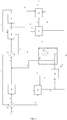
- the figure 1 schematically represents the ethanol dehydration process followed by the oxidation of the ethylene produced in the case of a concentrated ethanol feedstock with a recycling of the dilution water flow comprising ethanol resulting from the step h) the process.
- the ethanol feedstock (1) is preheated in an exchanger a) with the effluent from the dehydration step e) which enters the exchanger via the pipe (7).
- the preheated ethanol feedstock is then introduced into a pre-treatment zone b) via line (2).
- the pretreated ethanol feed is then mixed in line 3 with the non-vaporized flow of dilution water comprising ethanol from the recycle and vaporization zone h) which is recycled to serve as a reaction diluent via the lines (23).
- This mixture constituting the vaporization charge, is introduced via the line (3) into the vaporization step c) in which the said mixture undergoes heat exchange with the effluent from the dehydration step e) which enters the exchanger via the pipe (23) so as to produce a vaporized charge.
- the latent heat, also called enthalpy of condensation, of the effluent from the dehydration step e) is used to vaporize the vaporization charge, without external heat input.
- the vaporized charge is then sent via line (4) in the compression and overheating step d).
- said vaporized charge is compressed and superheated, and the effluent from the gaseous state of the dewatering section e) is "desuperheated" without being condensed.
- step e) Said vaporized, compressed and superheated feedstock is then mixed with the vaporized stream of dilution water comprising ethanol from step h) of recycling and vaporization and then introduced into step e) in which it passes through a furnace or any other equipment known to those skilled in the art so as to bring it to a temperature compatible with the temperature of the dehydration reaction.
- the effluent from step a) is sent via line (8) into separation section f) where it is separated into an effluent comprising ethylene (9) and an effluent comprising water (14). ).
- the effluent comprising ethylene is sent to the compression step i) via the pipe (9).
- Stage i) makes it possible to bring said effluent comprising ethylene to a pressure sufficient to allow its purification and preferably compatible with the feed pressure of the oxidation section j).
- Step i) also makes it possible to purify the effluent comprising ethylene by separating at least one stream comprising the light gases (17) and a stream of water and unreacted ethanol (18) recycled to the stage g) purification.
- the compressed and purified effluent comprising ethylene (10) from step i) is sent to the oxidation section j) or undergoes conversion to ethylene oxide.
- Step j) makes it possible to form a stream comprising ethylene oxide (11).
- the heat of reaction of step j) makes it possible to vaporize the quenching fluid (13) which is then recycled via line (12) to the recycling and vaporization step h).
- the effluent comprising water from step f) is sent via line (14) in a purification step g). At least one dilution water stream comprising the unconverted ethanol and at least one treated water stream (19) are separated. A stream containing the light gases and unconverted ethanol (21) is also separated and recycled to step f).
- All of said flow of dilution water comprising unconverted ethanol from purification step g) is sent to the recycling and vaporization step h) where it is divided into two streams (15) and (23) .
- the flow (15) is optionally pumped at a pressure that is compatible with the injection of the flow (16) upstream of step (e) and then is vaporized partially or totally by means of heat exchange using the condensation of the fluid (12). ). vaporized quenching from oxidation j).
- the condensed quench fluid is recycled via the line (13) into the oxidation section j).
- the effluent from the vaporized step (h) (16) is incorporated upstream of the dehydration step e) with the pretreated ethanol feedstock.
- the non-vaporized part (23) resulting from stage h) is recycled upstream of stage c) of vaporization.
- the liquid part can advantageously be relaxed and mixed with the flow (23).
- Example 1 illustrates a process according to the invention.
- the ethanol feedstock is produced by fermentation of wheat, without extraction of glutens, by a dry milling method according to the Anglo-Saxon term.
- Said ethanol feed is introduced at a flow rate of 45 664 kg / h in an E1 exchanger at a pressure equal to 1.15 MPa and is heated while remaining in the liquid phase to a temperature of 120 ° C. against the effluent from the last adiabatic reactor of step e).
- the heated ethanol feed is pretreated on a TA801 resin to remove traces of nitrogen compounds. During this pretreatment, a part of the ethanol is converted into DEE.
- the characteristics of the raw and pretreated ethanol feed are given in Table 1. Table 1: Characteristics of ethanol feed before and after pretreatment (percentages by mass) ETHANOL LOAD ETHANOL AFTER PRETREATMENT ETHANOL 91.2% 82.1% H2O 8.7% 10.5% DEE 0% 7.3% NITROGEN COMPOUNDS 0.005% 0.000%
- the vaporization charge consisting of the pretreated ethanol feed mixed with 85380 kg / h of dilution water and unconverted ethanol recycled according to step (h), is introduced into an exchanger E2 at a pressure equal to 0, 37 MPa.
- the vaporization charge enters the exchanger E2 at 113 ° C. and is therefore already vaporized at 8% by mass.
- the inlet pressure of the exchanger E2 has been adjusted so that the thermal approach with the flow from the last adiabatic reactor of step e) is at least 15 ° C.
- step c) the majority of the latent heat of the aqueous phase of the effluent from the last adiabatic reactor of step e) is recovered to vaporize the vaporization charge without external heat input.
- 51.9 MW are exchanged between said vaporization charge and said effluent.
- the vaporized charge is then compressed in a radial compressor K1 with an integrated multiplier so that the pressure of said vaporized charge is equal to 0.695 MPa at the end of the compression.
- the compressed charge is then heated in a single-phase gas-phase exchanger E 3 by heat exchange with the effluent from the adiabatic reactor of step e).
- said compressed charge is superheated at a temperature of 419 ° C. and the effluent resulting, in the gaseous state, from the last adiabatic reactor of step e) is "desuperheated" without being condensed and has a temperature of 273 ° C.
- the dehydration stage (e) comprises two furnaces and two adiabatic reactors in series. Said charge compressed and heated in said monophasic gas-type exchanger is then mixed with 55590 kg / h of vaporized dilution water from step (h) recycling and vaporization. This mixture is then introduced into an oven so as to bring it to an inlet temperature in the first adiabatic reactor of step e) compatible with the temperature of the dehydration reaction and conversion of DEE to highly endothermic ethylene, that is, at a temperature of 470 ° C.
- the outlet temperature of the last adiabatic reactor of step e) is 420 ° C.
- the dilution ratio at the reactor inlet (ie the water / ethanol mass ratio) is 3.
- the entrapment of the nitrogen compounds in the pretreatment step b) makes it possible to significantly reduce the temperature at the inlet of the first adiabatic reactor of step e).
- Said compressed and heated charge is introduced into the first adiabatic reactor at an inlet pressure of 0.595 MPa.
- the pressure of the effluent at the outlet of the last adiabatic reactor of step e) is 0.500 MPa.
- the dehydration step e) is carried out at a weight hourly weight of 7 h -1 .
- the adiabatic reactor contains a fixed bed of dehydration catalyst, said catalyst comprising 80% by weight of zeolite ZSM-5 treated with H 3 PO 4 so that the phosphorus content P is 3% by weight.
- the conversion of the ethanol feedstock in step e) is 95%.
- the effluent from the last adiabatic reactor of step e) then undergoes the three heat exchanges described above and is sent to a gas / liquid separation column.
- An effluent comprising ethylene at a pressure of 0.36 MPa is separated as well as an effluent comprising water. This separation is achieved by the use of a gas / liquid separation column, with recycling of the water produced at the bottom of the column to the column head and after cooling and injection of neutralizing agent.
- a dilution water stream comprising the unconverted ethanol (15) and a stream containing the light gases (21) are then separated by conventional low pressure distillation of the raw water.
- a stream of treated water is separated (19) and constitutes the purge of the process, its partial flow of water corresponds to the water formed by the dehydration reaction of step (e).
- the dilution water stream comprising unconverted ethanol is divided into two streams (23) and (15).
- the flow (15) is sent into a reboiler for vaporizing it through the heat provided by the flow (12) from the oxidation section (j). 35 MW are exchanged in this stage and make it possible to vaporize 100% by mass of the stream (15).
- the hot stream from step (j) is condensed and recycled to the reactor of the oxidation step (j). This flow consists solely of 65914 kg / h of distilled water, its inlet pressure in step (h) is 1.5 MPa at its dew point, here 200 ° C.
- the vaporized stream (16) is recycled upstream of step (r) and the liquid stream (23) is recycled upstream of step (c).
- the effluent comprising ethylene then undergoes compression to raise its pressure to 2.78 MPa before its final purification carried out with a cryogenic distillation.
- a light gas stream is separated (17) at the top of this column and a condensate stream comprising water and ethanol is recycled to step g).
- the exotherm of the reaction, and therefore its selectivity, is limited by a high dilution of the reaction medium with methane which is recycled in the process.
- the purification of the methane is carried out by means of an absorption column using a solution of potassium carbonate.
- the reactor is a multitubular reactor capable of generating 65914 kg / h of saturated steam at a pressure of 1.5 MPa. This steam is sent to the section (h) recycling and vaporization via the stream (12).
- the separation of the ethylene oxide is carried out in a water absorption column followed by a stripping column.
- a mixture of oxygen and makeup methane is injected into the oxidation section (j) via line (22).
- the purified ethylene oxide is extracted into the stream (11) before being sent to a conversion section to ethylene glycol.
- the light compounds are C3 and C4 hydrocarbon compounds, as well as hydrogen and carbon dioxide.
- the selectivity of the ethanol conversion process to ethylene is 99%.
- This example shows that the exchanger E3 allows to recover 35MW of thermal energy from the oxidation section to achieve the vaporization of the dilution water of the dewatering section. Since the thermal level of this heat source is much higher (200 ° C. in this example) than the vaporization temperature of the dilution water comprising ethanol (approximately 135 ° C. in this example), the flow density of heat through the exchange E3 is high compared to a method according to the prior art or vaporization of the dilution water would be achieved by exchange with the effluent of step e) dehydration.
- the fact of using a closed loop of distilled water for the heat recovery produced in the oxidation step j) has the advantage of not requiring a purification section of the quenching water before its recycling (compared to a process where the dilution water is directly used as a quenching fluid in the calandria of the oxidation reactor before being injected into the dewatering section).
- step g) The fact of not compressing the entire flow of dilution water comprising ethanol from step g) makes it possible to reduce the power required for compression in step d) by 40% compared to a process according to the prior art or dilution water flow comprising ethanol from step g) is recycled completely upstream of step (c) of vaporization.
Landscapes
- Chemical & Material Sciences (AREA)
- Organic Chemistry (AREA)
- Chemical Kinetics & Catalysis (AREA)
- Organic Low-Molecular-Weight Compounds And Preparation Thereof (AREA)
- Epoxy Compounds (AREA)
- Low-Molecular Organic Synthesis Reactions Using Catalysts (AREA)
Applications Claiming Priority (2)
| Application Number | Priority Date | Filing Date | Title |
|---|---|---|---|
| FR1351163A FR3001969B1 (fr) | 2013-02-12 | 2013-02-12 | Procede de production d'oxyde d'ethylene a partir d'un flux d'ethanol thermiquement integre |
| PCT/FR2014/050227 WO2014125192A1 (fr) | 2013-02-12 | 2014-02-06 | Procédé de production d'oxyde d'ethylène a partir d'un flux d'éthanol thermiquement intégré |
Publications (2)
| Publication Number | Publication Date |
|---|---|
| EP2956447A1 EP2956447A1 (fr) | 2015-12-23 |
| EP2956447B1 true EP2956447B1 (fr) | 2018-01-17 |
Family
ID=48570251
Family Applications (1)
| Application Number | Title | Priority Date | Filing Date |
|---|---|---|---|
| EP14706901.7A Active EP2956447B1 (fr) | 2013-02-12 | 2014-02-06 | Procédé de production d'oxyde d'ethylène a partir d'un flux d'éthanol thermiquement intégré |
Country Status (11)
Families Citing this family (6)
| Publication number | Priority date | Publication date | Assignee | Title |
|---|---|---|---|---|
| FR3001968B1 (fr) * | 2013-02-12 | 2015-02-27 | IFP Energies Nouvelles | Procede de production d'oxyde d'ethylene a partir d'un flux d'ethanol thermo-mecaniquement integre |
| FR3026406B1 (fr) * | 2014-09-26 | 2016-12-09 | Ifp Energies Now | Procede de deshydratation isomerisante d'une charge alcool primaire substitue en position 2 par un groupement alkyl sur un catalyseur comprenant une zeolithe de type fer |
| US11180609B2 (en) | 2018-08-02 | 2021-11-23 | Saudi Aramco Technologies Company | Sustainable polymer compositions and methods |
| EP3858820A1 (en) * | 2020-01-29 | 2021-08-04 | Clariant International Ltd | Reactor concept and process for preparing ethylene oxide from ethanol |
| US11718920B2 (en) | 2020-12-08 | 2023-08-08 | Wisconsin Alumni Research Foundation | Electrochemical, dehydrogenation, epoxidation, substitution, and halogenation of hydrocarbons and hydrocarbon derivatives |
| CN115322068B (zh) * | 2022-08-30 | 2023-03-28 | 天津大学 | 乙醇脱水制乙烯热耦合方法及装置 |
Family Cites Families (17)
| Publication number | Priority date | Publication date | Assignee | Title |
|---|---|---|---|---|
| US3119837A (en) * | 1961-01-31 | 1964-01-28 | Shell Int Research | Curve |
| US3119387A (en) * | 1962-07-09 | 1964-01-28 | Belson Mfg Company | Grill-carried door |
| BR7705256A (pt) | 1977-08-09 | 1979-04-03 | Petroleo Brasileiro Sa | Processo e preparacao de eteno |
| BR8101487A (pt) * | 1981-03-13 | 1982-10-26 | Petroleo Brasileiro Sa | Processo de desidratacao de um alcool de baixo peso molecular |
| US5145824A (en) | 1991-01-22 | 1992-09-08 | Shell Oil Company | Ethylene oxide catalyst |
| DE19843654A1 (de) * | 1998-09-23 | 2000-03-30 | Basf Ag | Verfahren zur Herstellung von Ethylenoxid durch Direktoxidation von Ethylen mit Luft oder Sauerstoff |
| JP5421587B2 (ja) * | 2005-03-22 | 2014-02-19 | シエル・インターナシヨナル・リサーチ・マートスハツペイ・ベー・ヴエー | エチレンオキシドの製造のための反応器システムおよびプロセス |
| BRPI0601803A (pt) * | 2006-05-18 | 2008-02-19 | Helcio Valladares Barrocas | processo para produção de eteno a partir de álcool etìlico |
| CA2713172C (en) | 2008-02-07 | 2013-06-18 | Total Petrochemicals Research Feluy | Dehydration of alcohols in the presence of an inert component |
| WO2009098262A1 (en) | 2008-02-07 | 2009-08-13 | Total Petrochemicals Research Feluy | Dehydration of alcohols on crystalline silicates |
| US20110137096A1 (en) | 2008-02-07 | 2011-06-09 | Total Petrochemicals Research Feluy | Process to Make Olefins from Ethanol |
| US20110105815A1 (en) | 2008-02-07 | 2011-05-05 | Total Petrochemicals Research Feluy | Process to Make Olefins from Ethanol |
| US9242919B2 (en) | 2009-07-01 | 2016-01-26 | Dow Global Technologies Llc | Process to prepare olefins from aliphatic alcohols |
| JP2012214399A (ja) * | 2011-03-31 | 2012-11-08 | Nippon Shokubai Co Ltd | エチレンオキシドの製造方法 |
| FR2978146B1 (fr) * | 2011-07-21 | 2013-08-30 | IFP Energies Nouvelles | Procede de deshydratation de l'ethanol en ethylene a basse consommation energetique |
| FR2998568B1 (fr) * | 2012-11-27 | 2015-01-23 | IFP Energies Nouvelles | Procede de deshydratation de l'ethanol en ethylene a basse consommation |
| FR3001968B1 (fr) * | 2013-02-12 | 2015-02-27 | IFP Energies Nouvelles | Procede de production d'oxyde d'ethylene a partir d'un flux d'ethanol thermo-mecaniquement integre |
-
2013
- 2013-02-12 FR FR1351163A patent/FR3001969B1/fr active Active
-
2014
- 2014-02-06 EP EP14706901.7A patent/EP2956447B1/fr active Active
- 2014-02-06 RU RU2015138917A patent/RU2647597C2/ru active
- 2014-02-06 KR KR1020157021864A patent/KR102146597B1/ko active Active
- 2014-02-06 CA CA2899515A patent/CA2899515C/fr active Active
- 2014-02-06 JP JP2015556551A patent/JP6442418B2/ja active Active
- 2014-02-06 CN CN201480020971.0A patent/CN105308027B/zh active Active
- 2014-02-06 WO PCT/FR2014/050227 patent/WO2014125192A1/fr active Application Filing
- 2014-02-06 UA UAA201508807A patent/UA119535C2/uk unknown
- 2014-02-06 US US14/767,184 patent/US9353074B2/en active Active
- 2014-02-06 BR BR112015018332A patent/BR112015018332B1/pt active IP Right Grant
Also Published As
| Publication number | Publication date |
|---|---|
| RU2647597C2 (ru) | 2018-03-16 |
| KR102146597B1 (ko) | 2020-08-20 |
| CN105308027B (zh) | 2017-08-25 |
| CA2899515A1 (fr) | 2014-08-21 |
| CN105308027A (zh) | 2016-02-03 |
| FR3001969B1 (fr) | 2015-08-21 |
| RU2015138917A (ru) | 2017-03-20 |
| JP2016511242A (ja) | 2016-04-14 |
| CA2899515C (fr) | 2021-07-13 |
| US9353074B2 (en) | 2016-05-31 |
| FR3001969A1 (fr) | 2014-08-15 |
| KR20150115806A (ko) | 2015-10-14 |
| US20150376151A1 (en) | 2015-12-31 |
| BR112015018332A2 (pt) | 2017-07-18 |
| EP2956447A1 (fr) | 2015-12-23 |
| JP6442418B2 (ja) | 2018-12-19 |
| BR112015018332B1 (pt) | 2020-04-22 |
| UA119535C2 (uk) | 2019-07-10 |
| WO2014125192A1 (fr) | 2014-08-21 |
Similar Documents
| Publication | Publication Date | Title |
|---|---|---|
| EP2956446B1 (fr) | Procédé de production d'oxyde d'éthylène a partir d'un flux d'éthanol thermo-mécaniquement intégré | |
| EP2925706B1 (fr) | Procede de déshydratation de l'éthanol en éthylene a basse consommation énergétique | |
| EP2734490B1 (fr) | Procédé de déshydratation de l'éthanol en éthylène a basse consommation énergétique | |
| EP2956447B1 (fr) | Procédé de production d'oxyde d'ethylène a partir d'un flux d'éthanol thermiquement intégré | |
| WO2020120136A1 (fr) | Procede de deshydratation de l'ethanol en ethylene a basse consommation energetique | |
| WO2013050669A1 (fr) | Procede de deshydratation de l'ethanol dilue en ethylene a basse consommation energetique sans recyclage de l'eau | |
| EP2925707B1 (fr) | Procede de deshydratation d'ethanol en ethylene mettant en oeuvre un pretraitement de la charge | |
| WO2024132696A1 (fr) | Conversion d'une charge hydrocarbonee issue de la biomasse en sels d'acrylate |
Legal Events
| Date | Code | Title | Description |
|---|---|---|---|
| PUAI | Public reference made under article 153(3) epc to a published international application that has entered the european phase |
Free format text: ORIGINAL CODE: 0009012 |
|
| 17P | Request for examination filed |
Effective date: 20150914 |
|
| AK | Designated contracting states |
Kind code of ref document: A1 Designated state(s): AL AT BE BG CH CY CZ DE DK EE ES FI FR GB GR HR HU IE IS IT LI LT LU LV MC MK MT NL NO PL PT RO RS SE SI SK SM TR |
|
| AX | Request for extension of the european patent |
Extension state: BA ME |
|
| DAX | Request for extension of the european patent (deleted) | ||
| GRAP | Despatch of communication of intention to grant a patent |
Free format text: ORIGINAL CODE: EPIDOSNIGR1 |
|
| INTG | Intention to grant announced |
Effective date: 20170809 |
|
| RAP1 | Party data changed (applicant data changed or rights of an application transferred) |
Owner name: IFP ENERGIES NOUVELLES |
|
| GRAS | Grant fee paid |
Free format text: ORIGINAL CODE: EPIDOSNIGR3 |
|
| GRAA | (expected) grant |
Free format text: ORIGINAL CODE: 0009210 |
|
| AK | Designated contracting states |
Kind code of ref document: B1 Designated state(s): AL AT BE BG CH CY CZ DE DK EE ES FI FR GB GR HR HU IE IS IT LI LT LU LV MC MK MT NL NO PL PT RO RS SE SI SK SM TR |
|
| REG | Reference to a national code |
Ref country code: GB Ref legal event code: FG4D Free format text: NOT ENGLISH |
|
| REG | Reference to a national code |
Ref country code: CH Ref legal event code: EP |
|
| REG | Reference to a national code |
Ref country code: IE Ref legal event code: FG4D Free format text: LANGUAGE OF EP DOCUMENT: FRENCH |
|
| REG | Reference to a national code |
Ref country code: AT Ref legal event code: REF Ref document number: 964303 Country of ref document: AT Kind code of ref document: T Effective date: 20180215 |
|
| REG | Reference to a national code |
Ref country code: DE Ref legal event code: R096 Ref document number: 602014020016 Country of ref document: DE Ref country code: FR Ref legal event code: PLFP Year of fee payment: 5 |
|
| REG | Reference to a national code |
Ref country code: NL Ref legal event code: FP |
|
| REG | Reference to a national code |
Ref country code: LT Ref legal event code: MG4D |
|
| REG | Reference to a national code |
Ref country code: AT Ref legal event code: MK05 Ref document number: 964303 Country of ref document: AT Kind code of ref document: T Effective date: 20180117 |
|
| PG25 | Lapsed in a contracting state [announced via postgrant information from national office to epo] |
Ref country code: ES Free format text: LAPSE BECAUSE OF FAILURE TO SUBMIT A TRANSLATION OF THE DESCRIPTION OR TO PAY THE FEE WITHIN THE PRESCRIBED TIME-LIMIT Effective date: 20180117 Ref country code: CY Free format text: LAPSE BECAUSE OF FAILURE TO SUBMIT A TRANSLATION OF THE DESCRIPTION OR TO PAY THE FEE WITHIN THE PRESCRIBED TIME-LIMIT Effective date: 20180117 Ref country code: FI Free format text: LAPSE BECAUSE OF FAILURE TO SUBMIT A TRANSLATION OF THE DESCRIPTION OR TO PAY THE FEE WITHIN THE PRESCRIBED TIME-LIMIT Effective date: 20180117 Ref country code: LT Free format text: LAPSE BECAUSE OF FAILURE TO SUBMIT A TRANSLATION OF THE DESCRIPTION OR TO PAY THE FEE WITHIN THE PRESCRIBED TIME-LIMIT Effective date: 20180117 Ref country code: HR Free format text: LAPSE BECAUSE OF FAILURE TO SUBMIT A TRANSLATION OF THE DESCRIPTION OR TO PAY THE FEE WITHIN THE PRESCRIBED TIME-LIMIT Effective date: 20180117 Ref country code: NO Free format text: LAPSE BECAUSE OF FAILURE TO SUBMIT A TRANSLATION OF THE DESCRIPTION OR TO PAY THE FEE WITHIN THE PRESCRIBED TIME-LIMIT Effective date: 20180417 |
|
| PG25 | Lapsed in a contracting state [announced via postgrant information from national office to epo] |
Ref country code: BG Free format text: LAPSE BECAUSE OF FAILURE TO SUBMIT A TRANSLATION OF THE DESCRIPTION OR TO PAY THE FEE WITHIN THE PRESCRIBED TIME-LIMIT Effective date: 20180417 Ref country code: AT Free format text: LAPSE BECAUSE OF FAILURE TO SUBMIT A TRANSLATION OF THE DESCRIPTION OR TO PAY THE FEE WITHIN THE PRESCRIBED TIME-LIMIT Effective date: 20180117 Ref country code: RS Free format text: LAPSE BECAUSE OF FAILURE TO SUBMIT A TRANSLATION OF THE DESCRIPTION OR TO PAY THE FEE WITHIN THE PRESCRIBED TIME-LIMIT Effective date: 20180117 Ref country code: PL Free format text: LAPSE BECAUSE OF FAILURE TO SUBMIT A TRANSLATION OF THE DESCRIPTION OR TO PAY THE FEE WITHIN THE PRESCRIBED TIME-LIMIT Effective date: 20180117 Ref country code: SE Free format text: LAPSE BECAUSE OF FAILURE TO SUBMIT A TRANSLATION OF THE DESCRIPTION OR TO PAY THE FEE WITHIN THE PRESCRIBED TIME-LIMIT Effective date: 20180117 Ref country code: IS Free format text: LAPSE BECAUSE OF FAILURE TO SUBMIT A TRANSLATION OF THE DESCRIPTION OR TO PAY THE FEE WITHIN THE PRESCRIBED TIME-LIMIT Effective date: 20180517 Ref country code: LV Free format text: LAPSE BECAUSE OF FAILURE TO SUBMIT A TRANSLATION OF THE DESCRIPTION OR TO PAY THE FEE WITHIN THE PRESCRIBED TIME-LIMIT Effective date: 20180117 Ref country code: GR Free format text: LAPSE BECAUSE OF FAILURE TO SUBMIT A TRANSLATION OF THE DESCRIPTION OR TO PAY THE FEE WITHIN THE PRESCRIBED TIME-LIMIT Effective date: 20180418 |
|
| REG | Reference to a national code |
Ref country code: CH Ref legal event code: PL |
|
| PG25 | Lapsed in a contracting state [announced via postgrant information from national office to epo] |
Ref country code: MT Free format text: LAPSE BECAUSE OF FAILURE TO SUBMIT A TRANSLATION OF THE DESCRIPTION OR TO PAY THE FEE WITHIN THE PRESCRIBED TIME-LIMIT Effective date: 20180117 |
|
| REG | Reference to a national code |
Ref country code: DE Ref legal event code: R097 Ref document number: 602014020016 Country of ref document: DE |
|
| PG25 | Lapsed in a contracting state [announced via postgrant information from national office to epo] |
Ref country code: IT Free format text: LAPSE BECAUSE OF FAILURE TO SUBMIT A TRANSLATION OF THE DESCRIPTION OR TO PAY THE FEE WITHIN THE PRESCRIBED TIME-LIMIT Effective date: 20180117 Ref country code: RO Free format text: LAPSE BECAUSE OF FAILURE TO SUBMIT A TRANSLATION OF THE DESCRIPTION OR TO PAY THE FEE WITHIN THE PRESCRIBED TIME-LIMIT Effective date: 20180117 Ref country code: AL Free format text: LAPSE BECAUSE OF FAILURE TO SUBMIT A TRANSLATION OF THE DESCRIPTION OR TO PAY THE FEE WITHIN THE PRESCRIBED TIME-LIMIT Effective date: 20180117 Ref country code: MC Free format text: LAPSE BECAUSE OF FAILURE TO SUBMIT A TRANSLATION OF THE DESCRIPTION OR TO PAY THE FEE WITHIN THE PRESCRIBED TIME-LIMIT Effective date: 20180117 Ref country code: EE Free format text: LAPSE BECAUSE OF FAILURE TO SUBMIT A TRANSLATION OF THE DESCRIPTION OR TO PAY THE FEE WITHIN THE PRESCRIBED TIME-LIMIT Effective date: 20180117 |
|
| PLBE | No opposition filed within time limit |
Free format text: ORIGINAL CODE: 0009261 |
|
| STAA | Information on the status of an ep patent application or granted ep patent |
Free format text: STATUS: NO OPPOSITION FILED WITHIN TIME LIMIT |
|
| REG | Reference to a national code |
Ref country code: IE Ref legal event code: MM4A |
|
| PG25 | Lapsed in a contracting state [announced via postgrant information from national office to epo] |
Ref country code: SM Free format text: LAPSE BECAUSE OF FAILURE TO SUBMIT A TRANSLATION OF THE DESCRIPTION OR TO PAY THE FEE WITHIN THE PRESCRIBED TIME-LIMIT Effective date: 20180117 Ref country code: DK Free format text: LAPSE BECAUSE OF FAILURE TO SUBMIT A TRANSLATION OF THE DESCRIPTION OR TO PAY THE FEE WITHIN THE PRESCRIBED TIME-LIMIT Effective date: 20180117 Ref country code: LU Free format text: LAPSE BECAUSE OF NON-PAYMENT OF DUE FEES Effective date: 20180206 Ref country code: CZ Free format text: LAPSE BECAUSE OF FAILURE TO SUBMIT A TRANSLATION OF THE DESCRIPTION OR TO PAY THE FEE WITHIN THE PRESCRIBED TIME-LIMIT Effective date: 20180117 Ref country code: CH Free format text: LAPSE BECAUSE OF NON-PAYMENT OF DUE FEES Effective date: 20180228 Ref country code: SK Free format text: LAPSE BECAUSE OF FAILURE TO SUBMIT A TRANSLATION OF THE DESCRIPTION OR TO PAY THE FEE WITHIN THE PRESCRIBED TIME-LIMIT Effective date: 20180117 Ref country code: LI Free format text: LAPSE BECAUSE OF NON-PAYMENT OF DUE FEES Effective date: 20180228 |
|
| 26N | No opposition filed |
Effective date: 20181018 |
|
| GBPC | Gb: european patent ceased through non-payment of renewal fee |
Effective date: 20180417 |
|
| PG25 | Lapsed in a contracting state [announced via postgrant information from national office to epo] |
Ref country code: IE Free format text: LAPSE BECAUSE OF NON-PAYMENT OF DUE FEES Effective date: 20180206 |
|
| PG25 | Lapsed in a contracting state [announced via postgrant information from national office to epo] |
Ref country code: GB Free format text: LAPSE BECAUSE OF NON-PAYMENT OF DUE FEES Effective date: 20180417 Ref country code: SI Free format text: LAPSE BECAUSE OF FAILURE TO SUBMIT A TRANSLATION OF THE DESCRIPTION OR TO PAY THE FEE WITHIN THE PRESCRIBED TIME-LIMIT Effective date: 20180117 |
|
| PG25 | Lapsed in a contracting state [announced via postgrant information from national office to epo] |
Ref country code: TR Free format text: LAPSE BECAUSE OF FAILURE TO SUBMIT A TRANSLATION OF THE DESCRIPTION OR TO PAY THE FEE WITHIN THE PRESCRIBED TIME-LIMIT Effective date: 20180117 |
|
| PG25 | Lapsed in a contracting state [announced via postgrant information from national office to epo] |
Ref country code: PT Free format text: LAPSE BECAUSE OF FAILURE TO SUBMIT A TRANSLATION OF THE DESCRIPTION OR TO PAY THE FEE WITHIN THE PRESCRIBED TIME-LIMIT Effective date: 20180117 |
|
| PG25 | Lapsed in a contracting state [announced via postgrant information from national office to epo] |
Ref country code: MK Free format text: LAPSE BECAUSE OF NON-PAYMENT OF DUE FEES Effective date: 20180117 Ref country code: HU Free format text: LAPSE BECAUSE OF FAILURE TO SUBMIT A TRANSLATION OF THE DESCRIPTION OR TO PAY THE FEE WITHIN THE PRESCRIBED TIME-LIMIT; INVALID AB INITIO Effective date: 20140206 |
|
| PGFP | Annual fee paid to national office [announced via postgrant information from national office to epo] |
Ref country code: NL Payment date: 20250224 Year of fee payment: 12 |
|
| PGFP | Annual fee paid to national office [announced via postgrant information from national office to epo] |
Ref country code: DE Payment date: 20250226 Year of fee payment: 12 |
|
| PGFP | Annual fee paid to national office [announced via postgrant information from national office to epo] |
Ref country code: BE Payment date: 20250224 Year of fee payment: 12 |
|
| PGFP | Annual fee paid to national office [announced via postgrant information from national office to epo] |
Ref country code: FR Payment date: 20250224 Year of fee payment: 12 |