EP2956080B1 - Systeme zur proximalen steuerung eines chirurgischen instruments - Google Patents
Systeme zur proximalen steuerung eines chirurgischen instruments Download PDFInfo
- Publication number
- EP2956080B1 EP2956080B1 EP14751850.0A EP14751850A EP2956080B1 EP 2956080 B1 EP2956080 B1 EP 2956080B1 EP 14751850 A EP14751850 A EP 14751850A EP 2956080 B1 EP2956080 B1 EP 2956080B1
- Authority
- EP
- European Patent Office
- Prior art keywords
- instrument
- proximal
- surgical
- chassis
- actuator
- Prior art date
- Legal status (The legal status is an assumption and is not a legal conclusion. Google has not performed a legal analysis and makes no representation as to the accuracy of the status listed.)
- Active
Links
- 230000033001 locomotion Effects 0.000 claims description 63
- 238000000034 method Methods 0.000 description 16
- 230000007246 mechanism Effects 0.000 description 15
- 210000000707 wrist Anatomy 0.000 description 11
- 239000012636 effector Substances 0.000 description 9
- 238000003780 insertion Methods 0.000 description 9
- 230000037431 insertion Effects 0.000 description 9
- 238000001356 surgical procedure Methods 0.000 description 7
- 230000006870 function Effects 0.000 description 5
- 238000012545 processing Methods 0.000 description 4
- 238000002432 robotic surgery Methods 0.000 description 4
- 238000012978 minimally invasive surgical procedure Methods 0.000 description 3
- 230000004044 response Effects 0.000 description 3
- 239000004065 semiconductor Substances 0.000 description 3
- XEEYBQQBJWHFJM-UHFFFAOYSA-N Iron Chemical compound [Fe] XEEYBQQBJWHFJM-UHFFFAOYSA-N 0.000 description 2
- 208000002847 Surgical Wound Diseases 0.000 description 2
- 239000000919 ceramic Substances 0.000 description 2
- 210000003679 cervix uteri Anatomy 0.000 description 2
- 238000004891 communication Methods 0.000 description 2
- 230000008878 coupling Effects 0.000 description 2
- 238000010168 coupling process Methods 0.000 description 2
- 238000005859 coupling reaction Methods 0.000 description 2
- 238000006073 displacement reaction Methods 0.000 description 2
- 230000000694 effects Effects 0.000 description 2
- 210000000867 larynx Anatomy 0.000 description 2
- 229910052751 metal Inorganic materials 0.000 description 2
- 239000002184 metal Substances 0.000 description 2
- 150000002739 metals Chemical class 0.000 description 2
- 230000003287 optical effect Effects 0.000 description 2
- 229920003023 plastic Polymers 0.000 description 2
- 239000004033 plastic Substances 0.000 description 2
- 210000003857 wrist joint Anatomy 0.000 description 2
- 241001631457 Cannula Species 0.000 description 1
- 210000003484 anatomy Anatomy 0.000 description 1
- 230000005540 biological transmission Effects 0.000 description 1
- 210000000481 breast Anatomy 0.000 description 1
- 230000008859 change Effects 0.000 description 1
- 238000010276 construction Methods 0.000 description 1
- 230000002939 deleterious effect Effects 0.000 description 1
- 230000001419 dependent effect Effects 0.000 description 1
- 238000002405 diagnostic procedure Methods 0.000 description 1
- 238000007429 general method Methods 0.000 description 1
- 238000009802 hysterectomy Methods 0.000 description 1
- 229910052742 iron Inorganic materials 0.000 description 1
- 239000011159 matrix material Substances 0.000 description 1
- 238000012986 modification Methods 0.000 description 1
- 230000004048 modification Effects 0.000 description 1
- 230000008569 process Effects 0.000 description 1
- 238000011084 recovery Methods 0.000 description 1
Images


Classifications
-
- A—HUMAN NECESSITIES
- A61—MEDICAL OR VETERINARY SCIENCE; HYGIENE
- A61B—DIAGNOSIS; SURGERY; IDENTIFICATION
- A61B34/00—Computer-aided surgery; Manipulators or robots specially adapted for use in surgery
- A61B34/30—Surgical robots
- A61B34/35—Surgical robots for telesurgery
-
- A—HUMAN NECESSITIES
- A61—MEDICAL OR VETERINARY SCIENCE; HYGIENE
- A61B—DIAGNOSIS; SURGERY; IDENTIFICATION
- A61B34/00—Computer-aided surgery; Manipulators or robots specially adapted for use in surgery
- A61B34/30—Surgical robots
- A61B34/37—Master-slave robots
-
- A—HUMAN NECESSITIES
- A61—MEDICAL OR VETERINARY SCIENCE; HYGIENE
- A61B—DIAGNOSIS; SURGERY; IDENTIFICATION
- A61B34/00—Computer-aided surgery; Manipulators or robots specially adapted for use in surgery
- A61B34/30—Surgical robots
-
- A—HUMAN NECESSITIES
- A61—MEDICAL OR VETERINARY SCIENCE; HYGIENE
- A61B—DIAGNOSIS; SURGERY; IDENTIFICATION
- A61B34/00—Computer-aided surgery; Manipulators or robots specially adapted for use in surgery
- A61B34/70—Manipulators specially adapted for use in surgery
- A61B34/74—Manipulators with manual electric input means
-
- A—HUMAN NECESSITIES
- A61—MEDICAL OR VETERINARY SCIENCE; HYGIENE
- A61B—DIAGNOSIS; SURGERY; IDENTIFICATION
- A61B17/00—Surgical instruments, devices or methods, e.g. tourniquets
- A61B17/00234—Surgical instruments, devices or methods, e.g. tourniquets for minimally invasive surgery
-
- A—HUMAN NECESSITIES
- A61—MEDICAL OR VETERINARY SCIENCE; HYGIENE
- A61B—DIAGNOSIS; SURGERY; IDENTIFICATION
- A61B17/00—Surgical instruments, devices or methods, e.g. tourniquets
- A61B17/00234—Surgical instruments, devices or methods, e.g. tourniquets for minimally invasive surgery
- A61B2017/00292—Surgical instruments, devices or methods, e.g. tourniquets for minimally invasive surgery mounted on or guided by flexible, e.g. catheter-like, means
- A61B2017/003—Steerable
- A61B2017/00318—Steering mechanisms
- A61B2017/00323—Cables or rods
- A61B2017/00327—Cables or rods with actuating members moving in opposite directions
-
- A—HUMAN NECESSITIES
- A61—MEDICAL OR VETERINARY SCIENCE; HYGIENE
- A61B—DIAGNOSIS; SURGERY; IDENTIFICATION
- A61B17/00—Surgical instruments, devices or methods, e.g. tourniquets
- A61B2017/00477—Coupling
-
- A—HUMAN NECESSITIES
- A61—MEDICAL OR VETERINARY SCIENCE; HYGIENE
- A61B—DIAGNOSIS; SURGERY; IDENTIFICATION
- A61B34/00—Computer-aided surgery; Manipulators or robots specially adapted for use in surgery
- A61B34/30—Surgical robots
- A61B2034/301—Surgical robots for introducing or steering flexible instruments inserted into the body, e.g. catheters or endoscopes
-
- A—HUMAN NECESSITIES
- A61—MEDICAL OR VETERINARY SCIENCE; HYGIENE
- A61B—DIAGNOSIS; SURGERY; IDENTIFICATION
- A61B90/00—Instruments, implements or accessories specially adapted for surgery or diagnosis and not covered by any of the groups A61B1/00 - A61B50/00, e.g. for luxation treatment or for protecting wound edges
- A61B90/36—Image-producing devices or illumination devices not otherwise provided for
- A61B90/361—Image-producing devices, e.g. surgical cameras
Definitions
- the present disclosure is directed to surgical systems and methods for use in minimally invasive robotically assisted surgery, and more particularly to systems and methods for moving a surgical instrument about a pivot located proximally of an anatomical entry point.
- Minimally invasive medical techniques are intended to reduce the amount of extraneous tissue that is damaged during diagnostic or surgical procedures, thereby reducing patient recovery time, discomfort, and deleterious side effects.
- Minimally invasive robotic surgical or telesurgical systems have been developed to increase a surgeon's dexterity and to avoid some of the limitations on traditional minimally invasive techniques.
- the surgeon uses some form of remote control, e.g., a servomechanism or the like, to manipulate surgical instrument movements, rather than directly holding and moving the instruments by hand.
- the surgeon can be provided with an image of the surgical site at the surgical workstation. While viewing a two or three dimensional image of the surgical site on a display, the surgeon performs the surgical procedures on the patient by manipulating master control devices, which in turn control motion of the servomechanically operated instruments.
- the surgeon typically operates a master controller to control the motion of surgical instruments at the surgical site from a location that may be remote from the patient (e.g., across the operating room, in a different room, or a completely different building from the patient).
- the master controller usually includes one or more hand input devices, such as hand-held wrist gimbals, joysticks, exoskeletal gloves or the like, which are operatively coupled to the surgical instruments that are releasably coupled to a patient side surgical manipulator ("the slave").
- the master controller controls the instrument's position, orientation, and articulation at the surgical site.
- the slave is an electromechanical assembly which includes one or more arms, joints, linkages, servo motors, etc. that are connected together to support and control the surgical instruments.
- the surgical instruments including an endoscope
- the surgical instruments may be introduced directly into an open surgical site, through a natural orifice, or through cannulas into a body cavity.
- the surgical instruments controlled by the surgical manipulator, may be introduced into the body cavity through a single surgical incision site, multiple closely spaced incision sites on the patient's body, and/or one or more natural orifices in the patient anatomy.
- multiple surgical instruments may be introduced in a closely gathered cluster with nearly parallel instrument shafts.
- Previous surgical systems and techniques maintained a common center of motion, known as a "remote center,” at an area near the anatomical entry point.
- US 2007/173977 discloses a robotic arm including a parallel spherical five-bar linkage with a remote center of spherical rotation.
- the robotic arm movably supports an endoscopic camera.
- Two outboard links are pivotally coupled together. At least one of the two outboard links supports the endoscopic camera.
- Two inboard links are respectively pivotally coupled to the two outboard links such that the two inboard links are able to cross over one another.
- the two inboard links moveably support the two outboard links.
- a ground link is pivotally coupled to the two inboard links.
- the ground link moveably supports the two inboard links.
- Claim 1 defines the invention and the dependent claims disclose the preferred embodiments.
- the present invention provides a robotic surgical system as set out in the appended claims.
- a robotic surgical system comprises an instrument chassis having a proximal chassis portion and a distal chassis portion both positioned along a central axis of the instrument chassis, the distal chassis portion being positioned closer to a patient entry point than the proximal chassis portion during use of the surgical system.
- the system also comprises a surgical instrument having a shaft with a proximal instrument end and a distal instrument end, the shaft defining a central instrument axis, wherein the proximal instrument end is coupled to the proximal chassis portion; an instrument guide member configured to receive the ridged shaft of the surgical instrument and configured to moveably couple the surgical instrument to a distal bridge member disposed at the distal chassis portion such that the central instrument axis is moveable relative to the central chassis axis; an actuator mounted to the proximal chassis portion; and a linkage system operably interconnecting the actuator and the instrument guide member to transmit motion from the actuator to the instrument guide member to reorient the central instrument axis relative to the central chassis axis.
- an exemplary robotic surgical method which comprises providing an instrument chassis having a proximal mounting section and a distal mounting section.
- An instrument guide assembly is movably coupled to the distal mounting section.
- a pair of proximal actuators are coupled to the proximal mounting section, and a linkage system operably interconnects the actuators and the instrument guide assembly.
- the method further includes providing first control signals to one of the proximal actuators to cause the linkage system to move the instrument guide assembly in a first rotational degree of freedom.
- the method also includes providing second control signals to the other one of the proximal actuators to cause the linkage system to move the instrument guide assembly in a second rotational degree of freedom.
- a robotic surgical system which comprises an instrument chassis assembly having a proximal mounting section and a distal mounting section.
- the chassis includes an instrument interface coupled to the proximal mounting section.
- the surgical system further comprises an actuation system coupled to the proximal mounting section.
- the surgical system further comprises a linkage system operably coupled between the actuation system and the distal mounting section.
- the linkage system includes an instrument guide.
- the surgical system further includes a surgical instrument configured to couple with the instrument interface and the instrument guide.
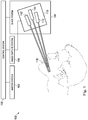
- a robotic surgical system is generally indicated by the reference numeral 100.
- the robotic surgical system 100 includes a master system 102, also referred to as a master or surgeon's console, for inputting a surgical procedure and a slave system 104, also referred to as a patient-side manipulator (PSM), for robotically moving surgical instruments at a surgical site within a patient.
- the robotic surgical system 100 is used to perform minimally invasive robotic surgery.
- a robotic surgical system architecture that can be used to implement the systems and techniques described in this disclosure is a da Vinci® Surgical System manufactured by Intuitive Surgical, Inc. of Sunnyvale, California.
- a smaller scale robotic surgical system with a single manipulator arm may be suitable for some procedures.
- the robotic surgical system 100 also includes an image capture system 106, which includes an image capture device, such as an endoscope, and related image processing hardware and software.
- the robotic surgical system 100 also includes a control system 108 that is operatively linked to sensors, motors, actuators, and other components of the master system 102 and the slave system 104 and to the image capture system 106.
- the system 100 is used by a system operator, generally a surgeon, who performs a minimally invasive surgical procedure on a patient.
- the system operator sees images, captured by the image capture system 106, presented for viewing at the master system 102.
- the control system 108 effects servomechanical movement of surgical instruments coupled to the robotic slave system 104.
- the control system 108 includes at least one processor and typically a plurality of processors for effecting control between the master system 102, the slave system 104, and the image capture system 106.
- the control system 108 also includes software programming instructions to implement some or all of the methods described herein. While control system 108 is shown as a single block in the simplified schematic of Fig. 1 , the system may comprise a number of data processing circuits (e.g., on the master system 102 and/or on the slave system 104), with at least a portion of the processing optionally being performed adjacent an input device, a portion being performed adjacent a manipulator, and the like. Any of a wide variety of centralized or distributed data processing architectures may be employed.
- control system 108 may support wireless communication protocols such as Bluetooth, IrDA, HomeRF, IEEE 802.11, DECT, and Wireless Telemetry.
- the robotic surgical system 100 further includes an instrument chassis 110 that couples to the slave system 104.
- the instrument chassis 110 provides a common platform for coupling surgical instruments 112 and endoscope 114 for introduction into a patient entry point 116.
- the patient entry point is a human mouth for providing access to the throat or larynx. It will be appreciated that the embodiments of this disclosure may be used for accessing body tissues through other natural or surgically created orifices.
- FIG. 2A is a schematic depiction of a minimally invasive surgical system 200 according to an embodiment of the present disclosure.
- the system 200 includes an instrument chassis 202 having a proximal section 204 and a distal section 206.
- the chassis 202 supports an endoscope 216.
- Instrument interfaces 208, 210 are movably mounted to the proximal section 204 of the instrument chassis 202.
- Surgical instrument 212 is mounted at its proximal end 213 to the instrument interface 208.
- Surgical instrument 214 is mounted at its proximal end 215 to the instrument interface 210.
- the interface 208 drives movable components in the surgical instrument 212 as described in U.S. 6,491,701 .
- the interface 210 drives the instrument 214 in a similar way.
- the surgical instruments 212, 214 are also movably coupled to the distal section 206 of the chassis 202.
- the instrument interfaces 208, 210 are mounted to the proximal section 204 of the chassis 202 such that rotational and linear motion is permitted.
- an instrument interface mounting or a flexible instrument shaft permits a pitch motion of the instrument interfaces 208, 210 relative to the chassis 202, a yaw motion of the instrument interfaces relative to the chassis and an insertion sliding motion of the instrument interfaces relative to the chassis.
- the system 200 functions similar to the manner in which chopsticks operate, in that small motions at the proximal end of the tool, near a pivot location, can correspond to larger motions at the distal end of the tool for manipulating objects.
- An actuation system 220 operates the components of instrument 212, such as an end effector and various wrist joints.
- An actuation system 222 operates the components of instrument 214, such as an end effector and various wrist joints.
- the actuation systems 220, 222 may include motors, actuators, drive systems, control systems, and other components for effecting the control of the instruments.
- An interface actuation system 224 controls the movement of the instrument 212 with respect to the chassis 202, and an interface actuation system 226 controls the movement of the instrument 214 with respect to the chassis 202.
- the reference system X 1 , Y 1 , Z 1 moves with the instrument 212 and the reference system X 2 , Y 2 , Z 2 moves with the instrument 214.
- the surgical system 200 may be configured to manipulate two instruments as shown, however in alternative embodiments, the system may be used to control the movement of more than two instruments.
- FIG. 2B is a schematic depiction of the minimally invasive surgical system 200 according to another embodiment of the present disclosure.
- the interface actuation system 224' includes a motor M1 driving an orientation system G (e.g., a gimbal system such as shown in FIG. 3 , gimbal components 334, 336) to control the proximal instrument interface 208 to move in a yaw movement (e.g., about the axis Y 1 ).
- the interface actuation system 224' also includes a motor M2 driving the orientation system G to control the proximal instrument interface 208 to move in a pitch movement (e.g., about the axis X 1 ).
- the interface actuation system 224' also includes a motor M3 to control the proximal instrument interface 208 to move axially along the axis Z 1 (e.g., for instrument insertion and withdrawal).
- the interface actuation system 226' may include similar components for effecting similar motion in the proximal instrument interface 210.
- the motion of the instruments may be controlled at the proximal end without support or control at the distal end.
- the interface actuation systems 224' and 226' are between the proximal instrument interfaces 208, 210.
- the surgical system 200 may be configured to manipulate two instruments as shown, however in alternative embodiments, the system may be used to control the movement of more than two instruments.
- FIG. 2C is a schematic depiction of the minimally invasive surgical system 200 according to another embodiment of the present disclosure.
- the interface actuation systems 224" and 226" are substantially similar to interface actuation systems 224' and 226', respectively, but in this embodiment, the proximal instrument interfaces 208, 210 are between the interface actuation systems 224" and 226".
- the surgical system 200 may be configured to manipulate two instruments as shown, however in alternative embodiments, the system may be used to control the movement of more than two instruments.
- Surgical instrument that was coupled to a robotic manipulator arm and to an insertion linkage system that constrained motion of the surgical instrument about a remote center of motion aligned along the shaft of the surgical instrument and coincident with a patient entry point, such as an entry incision. Further details of these methods and systems are described in U.S. Patents 5,817,084 and 6,441,577 .
- the embodiments of this disclosure remove the constraint of the remote center of motion at the patient entry point and permit a surgical instrument to pivot, with at least one rotational degree of freedom, about a location in space near or coincident with a proximal end of the surgical instrument.
- the proximal pivot locations may be, for example, approximately 30 cm from the patient entry point when using a surgical instrument with an approximate 40-50 cm length.
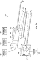
- FIG. 3 is a perspective view of a minimally invasive surgical system 300 according to an embodiment of the invention.
- the system 300 may be effective to avoid instrument collisions when working in small spaces.
- the system 300 includes an instrument chassis 302 and instrument interfaces 304, 306 for mounting surgical instruments 308, 310, respectively to the chassis.
- the surgical instrument 308 includes an end effector 308a and a wrist mechanism 308b.
- the surgical instrument 310 includes an end effector 310a and a wrist mechanism 310b.
- the surgical instruments 308, 310 move independently of one another based upon control input signals originating from the master system 102 and manipulator actuation signals from control system 108.
- the system 300 further includes a chassis mounted actuator system 312 and a linkage system 314 interconnecting the actuator system 312 with the surgical instruments 308, 310.
- An image capture system 316 is supported by the chassis 302 and is generally aligned along a central axis 318 (in a Z-axis direction) through the chassis.
- the instrument chassis 302 includes a proximal portion 320 and a distal portion 322.
- the system 300 generally includes a left lateral half 324 and a right lateral half 326 split generally about the central axis 318.
- the structures and function of the right and left lateral halves of the system 300 are generally the same. Therefore, a full description of the structure and function of the system 300 will be directed toward the left lateral half 324 with the understanding that the structures and function of the right lateral half 326 are the same.
- the instrument chassis 302 includes a bridge 328 located at a proximal end 329 of the chassis and includes a bridge 330 located at a distal end 331 of the chassis.
- a support tube 332 extends generally along the axis 318 and supports the image capture system 316.
- the support tube 332 rigidly connects the bridges 328, 330.
- the components of the instrument chassis may be formed of relatively rigid metals, plastics, or ceramics.
- the instrument chassis 302 further includes a gimbal support 334 pivotally connected to a gimbal plate 336.
- the gimbal system 334, 336 permits a yaw motion of the surgical instrument 308 (i.e., a rotational degree of freedom about a Y-direction axis) and permits a pitch motion of the surgical instrument 308 (i.e., a rotational degree of freedom about an X-direction axis.
- the motion of the gimbal system 334, 336 is passive, in that the motion is responsive to other actuated forces in the system 300 as will be described in greater detail.
- other joint or pivot systems including multi-axis gimbals, ball/ socket joints, and hinges, may provide one or more degrees of freedom at the proximal section of the chassis.
- the instrument chassis 302 also includes a guide (not shown) slidably engaged with a track (not shown) of the instrument interface 304.
- a guide 338 and track 340 are more clearly visible on the right half 326 of the system 300.
- the guide and track of the left half 324 permit insertion motion of the surgical instrument 308 generally along a Z-direction axis.
- Insertion drive systems 341a, 341b are coupled to the instruments 308, 310, respectively, to provide a driven insertion motion that moves the guide and track relative to one another.
- the insertion drive systems 341a, 341b include a drive motor and a drive mechanism such as a lead screw, ball screw, cable drive, or rack and pinion system.
- the motion of the guide/track may be passive, in that the motion is responsive to other actuated forces in the system 300.
- the left half of the actuation system 312 includes actuators 340, 342 coupled to the chassis 302.
- the actuators 340, 342 each include a motor M1, M2, respectively with a drive mechanism that provides variable and controllable force and position control and an encoder E1, E2, respectively for providing the control system 108 with the rotational position of the respective motor drive shafts. Further details of the actuation system, including suitable alternatives, are provided in U.S. Patent 5,792,135 .
- the actuators 340, 342 are coupled to the linkage system 314 which transmits the actuation.
- Each actuator provides a predetermined type of actuation.
- the actuator 340 provides an actuated pitch motion (about an X-direction axis)
- the actuator 342 provides an actuated yaw motion (about a Y-direction axis).
- the left half of the linkage system 314 includes an actuation rod 346 coupled between ball and socket joints 348, 350.
- the ball and socket joint 348 is coupled to the actuator 340.
- the linkage system 314 also includes an instrument guide 352 coupled to ball and socket joint 350.
- the instrument guide 352 is a tubular sleeve sized to receive the shaft of the surgical instrument 308.
- the instrument guide may be a ring, a tray, an opening tube, or other structure to movably link the surgical instrument to the chassis.
- the linkages 346, 348, 350 serve to transmit a motion from the actuator 340 to the instrument guide 352.
- the linkages may move the instrument guide 352 in a generally linear Y-direction or in a rotational pitch motion.
- the linkage system 314 also includes an actuation rod 354 coupled between ball and socket joints 356 (view obstructed by chassis), 358.
- the ball and socket joint 350 is coupled to the actuator 342.
- the instrument guide 352 is also coupled to the ball and socket joint 358.
- the linkages 354, 356, 358 serve to transmit a motion from the actuator 342 to the instrument guide 352.
- the linkages may move the instrument guide 352 in a generally X-direction or in a rotational yaw motion.
- the linkage system 314 further includes a ball joint 360 positioned within a socket formed in the distal bridge 330.
- the ball joint 360 is coupled to the instrument guide 352 to tether the instrument guide to the chassis 302.
- the components of the linkage system may be formed of relatively rigid metals, plastics, or ceramics.
- the components of the linkage system may be sterilizable or disposable.
- the components of the linkage system may have a small cross-sectional area to minimize the volume of the surgical equipment near the patient entry point.
- the rod linkages may have a diameter of approximately 1-3mm.
- other linkage components may be suitable to transmit a predetermined motion.
- Such alternative components may include unidirectional hinge joints, saddle joints, slide joints, flexible components such as springs, and fixed joints.
- the chassis 302 also supports the image capture system 316. More specifically, an endoscopic instrument 370 of the image capture system 316 extends through the support tube 332.
- the endoscopic instrument 370 has a viewing end 372 and is operatively connected to a viewer in the master system 102 to display an image captured at the viewing end to the surgeon or other viewer.
- the endoscopic instrument 370 may be fixed relative to the instrument chassis 302 or may be constrained to movement along an insertion axis generally aligned with the axis 318. Alternatively, the endoscopic instrument may be steerable, pivotable, or otherwise articulatable relative to the instrument chassis to change the viewpoint of the viewing end.
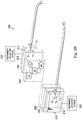
- the instrument interface 304 is shown in greater detail in FIG. 4 .
- a chassis interface plate 380 (which may be considered part of the chassis or part of the interface) is rotatably connected to an instrument interface plate 382.
- the rotational motion may be provided by a swivel joint, a ball/socket joint, or other known mechanism to provide full or partial rotational motion.
- the rotational motion between the plates 380, 382 is passive, in that the motion is responsive to other actuated forces in the system 300 as will be described in greater detail.
- Actuators 384, 386, 388, 390 are operably coupled to interface discs 392, 394, 396, 398, respectively.
- a more detailed description of the interface discs and their function in driving a predetermined motion in an attached surgical instrument is fully described, for example, in U.S. Patent No. 7,963,913, filed Dec. 10, 2006 , disclosing "Instrument Interface of Robotic Surgical System".
- each actuator includes a motor M and an encoder E.
- Each actuator 384-390 influences a specific motion in the end effector 308a and/or the wrist mechanism 308b of the surgical instrument 308.
- the actuator 384 may control a roll motion of the wrist mechanism 308b.
- the actuator 386 may control an actuated pitch motion of the wrist mechanism 308b.
- the actuator 388 and the actuator 390 may be coordinated to control actuated yaw and grip motions of the wrist mechanism.
- the assigned controls for the various actuators are merely examples.
- the actuators may be configured to control different motions in the surgical end effector or wrist. For example a single actuator may control grip while the coordinated combination of two actuators may control pitch and yaw of the wrist mechanism.
- the surgical instrument 308 includes a proximal housing 394 that couples to the interface 304.
- An instrument shaft 396 extends between the proximal housing 394 and the wrist mechanism 308b.
- the proximal housing 394 is coupled to the instrument interface 304 and the shaft 396 is inserted through the instrument guide 352.
- the shaft 396 passively slides within the instrument guide 352, in response to actuated forces in the system 300.
- actuators 340, 342 may provide coupled motion for pitch about axis X and for yaw about axis Y.
- the shaft 396 moves in yaw.
- the actuators 340, 342 move in different directions about the axis Y, the shaft 396 moves in pitch.
- the combined movement of the actuators 340, 342 may be governed by a 2x2 coupling matrix to move the shaft 396 in a range of directions.
- the system 300 as described, allows surgical access to body tissues through small natural or surgically created patient entry points.
- the system may be particularly suited for surgically accessing larynx or throat tissues via an open patient mouth or for accessing uterine tissues via the cervix to perform a vaginal hysterectomy.
- the system 300 may be used to perform surgery that may be tiring for a surgeon or require awkward positioning, such as breast surgery.
- the system 300 uses a minimized-size chassis that supports multiple surgical instruments.
- system 300 describes the use of two surgical instruments coupled to a common chassis, in alternative embodiments, three or more surgical instruments may be mounted and controlled from a common chassis.
- Locating the actuation system for controlling the movement of the instrument guides at a proximal section of the chassis minimizes the number and size of the structures needed at intermediate or distal locations along the instrument shaft to support and control multiple surgical instruments.
- the linkage system allows the actuation system to remotely control the motion of the instrument guides.
- a manipulator arm of the slave manipulator system 104 Prior to the use of the system 300, a manipulator arm of the slave manipulator system 104 is positioned and locked into place.
- the manipulator arm may be, for example, an arm of a da Vinci® Surgical System or may be a smaller scale manipulator with a linked arm having up to six degrees of freedom.
- the manipulator arm supporting the system 300 is not controlled by motors. It may be a passive lockable arm with one or more balanced joints having brakes or locks. A passive lockable arm may move freely in a released configuration, allowing the system to be positioned at the surgical site in a selected orientation. The passive lockable arm is then moved to a locked configuration with brakes holding the selected orientation.
- the system 300 may be held by an iron intern, a passive multi-jointed unbalanced arm that may be manually locked.
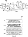
- an exemplary general method 400 of robotic surgery using the system 300 is provided.
- the housing 394 at the proximal end of the surgical instrument 308 is received into engagement with the instrument interface 304.
- the shaft 396 of the surgical instrument 309 is received into the instrument guide 352 at the distal end of the instrument chassis 302. More specifically, a distal or intermediate portion of the shaft 396 is received into the instrument guide 352.
- the actuation system 312 actuates linkage system 314 to move the instrument guide 352 relative to the instrument chassis 302. More specifically, the actuator 340 receives control signals from the control system 108 to drive the linkage system 314, including moving the ball and socket joint 348 which moves the rod 346.
- the actuator 342 receives control signals from the control system 108 to drive the linkage system 314, including moving the ball and socket joint 356 which moves the rod 354.
- instrument guide 352 moves along an X-direction axis.
- instrument guide 352 moves along a Y-direction axis. If only one rod 346 or 354 is moving, instrument guide 352 moves at an angle to both the X and Y-direction axes.
- the instrument guide 352 is tethered to the distal portion 330 of the chassis 302 by the ball joint 360.
- the proximal end of the surgical instrument 308 in response to the motor-driven actuation of the instrument guide 352, the proximal end of the surgical instrument 308 is permitted to passively move in multiple rotational degrees of freedom. More specifically, the proximal end of the surgical instrument 308 is permitted to passively rotate (yaw) with the gimbal plate 336 about a Y-direction axis. Additionally, the proximal end of the surgical instrument 308 is permitted to passively rotate (pitch) with the instrument interface plate 382 relative to the chassis interface plate 380 about an X-direction axis.
- the movement of the instrument guide 352 near a distal or intermediate location of the instrument shaft 396 affects a smaller scale motion at the proximal end of the surgical instrument 308.
- the smaller scale motion at the proximal end of the surgical instruments reduces or prevents proximal end instrument collisions.
- some existing systems may require spacing between instrument anatomic entry points of approximately 8-9cm. The systems of this disclosure may allow closer instrument spacing while avoiding robotic arm collisions.
- one or more of the gimbals or other rotational joints at the proximal end of the chassis may be replaced with fixed joints.
- a flexible instrument shaft may be used, allowing the surgical instrument a limited amount of rotational movement relative to the chassis.
- a parallel motion mechanism or "joggle joint” may be added to the distal end of the surgical instrument.
- the parallel motion mechanism includes a series of joints and linkages at the distal of the surgical instrument, proximal of the end effector, that permit lateral displacement of the end effector.
- a description of joggle joints and parallel motion mechanisms is provided in U.S. Patent No. 7,942,868 and U.S. Patent Application No. 12/489,566 , published as US2009326318 .
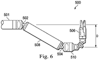
- Fig. 6 is a side view of a distal surgical instrument section 500 with a shaft 501.
- the section 500 includes a joint 502, a joint 504, a joint 506, and linkages 508, 510.
- the joints 502, 504 permit +/- 45° of rotation and the joint 510 permits +/- 90° of rotation.
- the joints 502, 504, 506 and linkages 508, 510 provide a lateral displacement D from the axis of the shaft 510, allowing for a greater surgical workspace between generally parallel surgical instruments.
- One or more elements in embodiments of the invention may be implemented in software to execute on a processor of a computer system such as control system 108.
- the elements of the embodiments of the invention are essentially the code segments to perform the necessary tasks.
- the program or code segments can be stored in a processor readable storage medium or device that may have been downloaded by way of a computer data signal embodied in a carrier wave over a transmission medium or a communication link.
- the processor readable storage device may include any medium that can store information including an optical medium, semiconductor medium, and magnetic medium.
- Processor readable storage device examples include an electronic circuit; a semiconductor device, a semiconductor memory device, a read only memory (ROM), a flash memory, an erasable programmable read only memory (EPROM); a floppy diskette, a CD-ROM, an optical disk, a hard disk, or other storage device,
- the code segments may be downloaded via computer networks such as the Internet, Intranet, etc.
Landscapes
- Health & Medical Sciences (AREA)
- Engineering & Computer Science (AREA)
- Life Sciences & Earth Sciences (AREA)
- Surgery (AREA)
- Robotics (AREA)
- Medical Informatics (AREA)
- Biomedical Technology (AREA)
- Heart & Thoracic Surgery (AREA)
- Nuclear Medicine, Radiotherapy & Molecular Imaging (AREA)
- Molecular Biology (AREA)
- Animal Behavior & Ethology (AREA)
- General Health & Medical Sciences (AREA)
- Public Health (AREA)
- Veterinary Medicine (AREA)
- Manipulator (AREA)
- Oral & Maxillofacial Surgery (AREA)
- Pathology (AREA)
Claims (9)
- Chirurgisches System, das Folgendes umfasst:ein Instrumentenchassis (302) mit einem proximalen Chassisabschnitt (320) und einem distalen Chassisabschnitt (322), die beide entlang einer Mittelachse des Instrumentenchassis (302) positioniert sind; wobei der distale Chassisabschnitt (322) während der Verwendung des chirurgischen Systems näher an einem Patienteneintrittspunkt als der proximale Chassisabschnitt (320) positioniert ist;ein chirurgisches Instrument (308), das einen Schaft mit einem proximalen Instrumentenende und einem distalen Instrumentenende aufweist; wobei der Schaft eine zentrale Instrumentenachse definiert, wobei das proximale Instrumentenende mit dem proximalen Chassisabschnitt (320) gekoppelt ist;ein Instrumentenführungselement (352), das dafür konfiguriert ist, den Schaft des chirurgischen Instruments (308) aufzunehmen, und das dafür konfiguriert ist, das chirurgische Instrument (308) beweglich mit einem distalen Brückenelement (330) zu koppeln, das an dem distalen Chassisabschnitt (322) angeordnet ist, so dass die zentrale Instrumentenachse relativ zur zentralen Chassisachse beweglich ist;einen Aktuator (340, 342), der an dem proximalen Chassisabschnitt (320) angebracht ist; undein Verbindungssystem (314), das den Aktuator (340, 342) und das Instrumentenführungselement (352) betriebsmäßig miteinander verbindet, um eine Bewegung vom Aktuator (340, 342) zum Instrumentenführungselement (352) zu übertragen, um die zentrale Instrumentenachse relativ zur zentralen Chassisachse neu auszurichten.
- System nach Anspruch 1, das ferner Folgendes umfasst:
eine Instrumentenkopplungsstelle (304), die beweglich mit dem proximalen Chassisabschnitt (320) verbunden ist, wobei das proximale Instrumentenende über die Instrumentenkopplungsstelle mit dem proximalen Chassisabschnitt (320) verbunden ist. - System nach Anspruch 2, wobei die Instrumentenkopplungsstelle verschiebbar mit dem proximalen Chassisabschnitt (320) gekoppelt ist.
- System nach Anspruch 2, das ferner Folgendes umfasst:
ein kardanisches System (334, 336), das die Instrumentenkopplungsstelle und den proximalen Chassisabschnitt (320) verbindet. - System nach Anspruch 2, das ferner Folgendes umfasst:
eine Schwenkverbindung zwischen der Instrumentenkopplungsstelle und dem proximalen Chassisabschnitt (320). - System nach Anspruch 1, wobei das Instrumentenchassis (302) ein proximales Stützelement (328) umfasst, das dafür bemessen ist, eine Bilderfassungsvorrichtung (316) zu tragen, und wobei das proximale Stützelement (328) durch ein Stützrohr (332) starr mit der distalen Brücke verbunden ist, wobei sich die Bilderfassungsvorrichtung durch das Stützrohr (332) und über die distale Brücke hinaus erstreckt.
- System nach Anspruch 1, wobei das Verbindungssystem eine Betätigungsstange (354) umfasst, die schwenkbar zwischen dem Aktuator (340, 342) und dem Instrumentenführungselement (352) gekoppelt ist, um das Instrumentenführungselement (352) in einem ersten Rotationsfreiheitsgrad zu bewegen.
- System nach Anspruch 7, wobei das Verbindungssystem ferner Folgendes umfasst: ein erstes Kugelgelenk (348), das den Aktuator (340, 342) und die Betätigungsstange verbindet, und ein zweites Kugelgelenk (350), das die Betätigungsstange und das Instrumentenführungselement (352) verbindet.
- System nach Anspruch 7, das ferner Folgendes umfasst: einen zweiten Aktuator (340, 342), der mit dem proximalen Chassisabschnitt (320) verbunden ist, und ein zweites Verbindungssystem, das den zweiten Aktuator (340, 342) und das Instrumentenführungselement (352) funktionsfähig miteinander verbindet, wobei das zweite Verbindungssystem eine zweite Betätigungsstange umfasst, die schwenkbar zwischen dem zweiten Aktuator (340, 342) und dem Instrumentenführungselement (352) gekoppelt ist, um das Instrumentenführungselement (352) in einem zweiten Rotationsfreiheitsgrad zu bewegen.
Applications Claiming Priority (2)
| Application Number | Priority Date | Filing Date | Title |
|---|---|---|---|
| US201361765482P | 2013-02-15 | 2013-02-15 | |
| PCT/US2014/016552 WO2014127271A1 (en) | 2013-02-15 | 2014-02-14 | Systems and methods for proximal control of a surgical instrument |
Publications (3)
| Publication Number | Publication Date |
|---|---|
| EP2956080A1 EP2956080A1 (de) | 2015-12-23 |
| EP2956080A4 EP2956080A4 (de) | 2016-07-27 |
| EP2956080B1 true EP2956080B1 (de) | 2020-08-05 |
Family
ID=51351758
Family Applications (1)
| Application Number | Title | Priority Date | Filing Date |
|---|---|---|---|
| EP14751850.0A Active EP2956080B1 (de) | 2013-02-15 | 2014-02-14 | Systeme zur proximalen steuerung eines chirurgischen instruments |
Country Status (6)
| Country | Link |
|---|---|
| US (4) | US9662176B2 (de) |
| EP (1) | EP2956080B1 (de) |
| JP (3) | JP6321047B2 (de) |
| KR (1) | KR102229337B1 (de) |
| CN (3) | CN108309453B (de) |
| WO (1) | WO2014127271A1 (de) |
Families Citing this family (27)
| Publication number | Priority date | Publication date | Assignee | Title |
|---|---|---|---|---|
| CA2816089A1 (en) | 2010-10-29 | 2012-05-03 | Richard H. Feins | Modular staged reality simulator |
| US9805625B2 (en) | 2010-10-29 | 2017-10-31 | KindHeart, Inc. | Surgical simulation assembly |
| US9662176B2 (en) | 2013-02-15 | 2017-05-30 | Intuitive Surgical Operations, Inc. | Systems and methods for proximal control of a surgical instrument |
| CN110251233B (zh) * | 2014-03-17 | 2023-02-03 | 直观外科手术操作公司 | 用于与基准靶对准的系统和方法 |
| USD779678S1 (en) | 2014-07-24 | 2017-02-21 | KindHeart, Inc. | Surgical tray |
| WO2016035086A2 (en) | 2014-09-04 | 2016-03-10 | Memic Innovative Surgery Ltd. | Device and system including mechanical arms |
| WO2016137612A1 (en) * | 2015-02-26 | 2016-09-01 | Covidien Lp | Robotically controlling remote center of motion with software and guide tube |
| US20160314711A1 (en) | 2015-04-27 | 2016-10-27 | KindHeart, Inc. | Telerobotic surgery system for remote surgeon training using robotic surgery station and remote surgeon station with display of actual animal tissue images and associated methods |
| US20170239005A1 (en) | 2015-09-04 | 2017-08-24 | Memic Innovative Surgery Ltd. | Actuation of a device comprising mechanical arms |
| WO2017048922A1 (en) | 2015-09-16 | 2017-03-23 | KindHeart, Inc. | Surgical simulation system and associated methods |
| CN108472087B (zh) | 2016-01-29 | 2021-08-27 | 直观外科手术操作公司 | 用于可变速外科手术器械的系统和方法 |
| CA2960354A1 (en) | 2016-03-09 | 2017-09-09 | Memic Innovative Surgery Ltd. | Modular device comprising mechanical arms |
| WO2017189317A1 (en) | 2016-04-26 | 2017-11-02 | KindHeart, Inc. | Telerobotic surgery system for remote surgeon training using robotic surgery station and remote surgeon station and an animating device |
| US11129683B2 (en) * | 2016-07-14 | 2021-09-28 | Intuitive Surgical Operations, Inc. | Systems and methods for controlling a surgical instrument |
| WO2018122993A1 (ja) * | 2016-12-28 | 2018-07-05 | オリンパス株式会社 | 医療システム、医療用オーバーチューブ、及び医療デバイスアダプタ |
| US10813710B2 (en) | 2017-03-02 | 2020-10-27 | KindHeart, Inc. | Telerobotic surgery system using minimally invasive surgical tool with variable force scaling and feedback and relayed communications between remote surgeon and surgery station |
| US10973592B2 (en) | 2017-03-09 | 2021-04-13 | Memie Innovative Surgery Ltd. | Control console for surgical device with mechanical arms |
| US11779410B2 (en) | 2017-03-09 | 2023-10-10 | Momentis Surgical Ltd | Control console including an input arm for control of a surgical mechanical arm |
| US10806532B2 (en) | 2017-05-24 | 2020-10-20 | KindHeart, Inc. | Surgical simulation system using force sensing and optical tracking and robotic surgery system |
| WO2019050797A1 (en) * | 2017-09-05 | 2019-03-14 | Intuitive Surgical Operations, Inc. | SYSTEMS AND METHODS FOR COMPUTER-AIDED REMOTE CONTROL SURGERY |
| CN109009449B (zh) * | 2018-06-22 | 2020-08-11 | 深圳市精锋医疗科技有限公司 | 操作臂及从操作设备 |
| CN109091240B (zh) * | 2018-06-22 | 2020-08-25 | 深圳市精锋医疗科技有限公司 | 单切口手术机器人 |
| CN109330700B (zh) * | 2018-07-31 | 2020-10-09 | 深圳市精锋医疗科技有限公司 | 从操作设备组件及手术机器人 |
| CN110870793B (zh) * | 2018-08-31 | 2024-04-05 | 新加坡国立大学 | 机械臂、微创手术机器人及其制造方法 |
| CN112739283A (zh) | 2018-09-17 | 2021-04-30 | 奥瑞斯健康公司 | 用于伴随医学规程的系统和方法 |
| CN110772324B (zh) * | 2018-12-20 | 2021-07-09 | 深圳市精锋医疗科技有限公司 | 连接组件、操作臂、从操作设备及手术机器人 |
| EP3900661A1 (de) * | 2020-04-23 | 2021-10-27 | Microsure B.V. | Chirurgisches robotersystem mit strebenanordnung |
Family Cites Families (36)
| Publication number | Priority date | Publication date | Assignee | Title |
|---|---|---|---|---|
| US5685821A (en) * | 1992-10-19 | 1997-11-11 | Arthrotek | Method and apparatus for performing endoscopic surgical procedures |
| EP0699053B1 (de) | 1993-05-14 | 1999-03-17 | Sri International | Chirurgiegerät |
| JPH07254207A (ja) * | 1994-01-25 | 1995-10-03 | Sony Corp | ディスクチェンジャ |
| US5814038A (en) * | 1995-06-07 | 1998-09-29 | Sri International | Surgical manipulator for a telerobotic system |
| ATE394995T1 (de) * | 1995-06-07 | 2008-05-15 | Stanford Res Inst Int | Chirurgischer manipulator für ein ferngesteuertes robotersystem |
| US5595965A (en) * | 1996-05-08 | 1997-01-21 | The Lubrizol Corporation | Biodegradable vegetable oil grease |
| US5792135A (en) | 1996-05-20 | 1998-08-11 | Intuitive Surgical, Inc. | Articulated surgical instrument for performing minimally invasive surgery with enhanced dexterity and sensitivity |
| US6331181B1 (en) | 1998-12-08 | 2001-12-18 | Intuitive Surgical, Inc. | Surgical robotic tools, data architecture, and use |
| AU5391999A (en) | 1998-08-04 | 2000-02-28 | Intuitive Surgical, Inc. | Manipulator positioning linkage for robotic surgery |
| US6522906B1 (en) | 1998-12-08 | 2003-02-18 | Intuitive Surgical, Inc. | Devices and methods for presenting and regulating auxiliary information on an image display of a telesurgical system to assist an operator in performing a surgical procedure |
| US6424885B1 (en) | 1999-04-07 | 2002-07-23 | Intuitive Surgical, Inc. | Camera referenced control in a minimally invasive surgical apparatus |
| US6645196B1 (en) | 2000-06-16 | 2003-11-11 | Intuitive Surgical, Inc. | Guided tool change |
| US6817974B2 (en) | 2001-06-29 | 2004-11-16 | Intuitive Surgical, Inc. | Surgical tool having positively positionable tendon-actuated multi-disk wrist joint |
| US20040243147A1 (en) | 2001-07-03 | 2004-12-02 | Lipow Kenneth I. | Surgical robot and robotic controller |
| US20070005002A1 (en) | 2005-06-30 | 2007-01-04 | Intuitive Surgical Inc. | Robotic surgical instruments for irrigation, aspiration, and blowing |
| WO2007075864A1 (en) | 2005-12-20 | 2007-07-05 | Intuitive Surgical, Inc. | Instrument interface of a robotic surgical system |
| US8182470B2 (en) | 2005-12-20 | 2012-05-22 | Intuitive Surgical Operations, Inc. | Telescoping insertion axis of a robotic surgical system |
| US8469945B2 (en) * | 2006-01-25 | 2013-06-25 | Intuitive Surgical Operations, Inc. | Center robotic arm with five-bar spherical linkage for endoscopic camera |
| US8518024B2 (en) * | 2006-04-24 | 2013-08-27 | Transenterix, Inc. | System and method for multi-instrument surgical access using a single access port |
| CA2650474A1 (en) | 2006-04-24 | 2007-11-08 | Synecor, Llc | Natural orifice surgical system |
| US7967813B2 (en) * | 2006-06-13 | 2011-06-28 | Intuitive Surgical Operations, Inc. | Surgical instrument control and actuation |
| US9089256B2 (en) * | 2008-06-27 | 2015-07-28 | Intuitive Surgical Operations, Inc. | Medical robotic system providing an auxiliary view including range of motion limitations for articulatable instruments extending out of a distal end of an entry guide |
| GB2451498A (en) | 2007-07-31 | 2009-02-04 | Prosurgics Ltd | A motorised manipulator that accommodates manual movement of a surgical instrument |
| US7677129B2 (en) | 2007-09-28 | 2010-03-16 | Intuitive Surgical, Inc. | Multiaxis counterbalance and positioning system using a spatial linkage |
| US9895813B2 (en) | 2008-03-31 | 2018-02-20 | Intuitive Surgical Operations, Inc. | Force and torque sensing in a surgical robot setup arm |
| JP5219073B2 (ja) * | 2008-05-19 | 2013-06-26 | 国立大学法人 名古屋工業大学 | 手術支援マニピュレータ |
| JP5435327B2 (ja) | 2008-10-27 | 2014-03-05 | 国立大学法人 名古屋工業大学 | 3軸を有する手術支援マニピュレータ |
| KR101075363B1 (ko) * | 2008-10-31 | 2011-10-19 | 정창욱 | 최소 침습 수술 도구를 포함하는 수술용 로봇 시스템 |
| JP5582561B2 (ja) | 2009-07-03 | 2014-09-03 | 国立大学法人九州大学 | 鉗子支持装置 |
| KR101180665B1 (ko) | 2009-07-03 | 2012-09-07 | 주식회사 이턴 | 하이브리드 수술용 로봇 시스템 및 수술용 로봇 제어방법 |
| US8551115B2 (en) | 2009-09-23 | 2013-10-08 | Intuitive Surgical Operations, Inc. | Curved cannula instrument |
| WO2011060031A1 (en) * | 2009-09-23 | 2011-05-19 | Intuitive Surgical Operations, Inc. | Curved cannula surgical system |
| US8603077B2 (en) * | 2010-05-14 | 2013-12-10 | Intuitive Surgical Operations, Inc. | Force transmission for robotic surgical instrument |
| US20130190774A1 (en) * | 2010-08-11 | 2013-07-25 | Ecole Polytechnique Ferderale De Lausanne (Epfl) | Mechanical positioning system for surgical instruments |
| KR102088541B1 (ko) | 2012-02-02 | 2020-03-13 | 그레이트 빌리프 인터내셔널 리미티드 | 기계화된 다중기구 수술 시스템 |
| US9662176B2 (en) | 2013-02-15 | 2017-05-30 | Intuitive Surgical Operations, Inc. | Systems and methods for proximal control of a surgical instrument |
-
2014
- 2014-02-14 US US14/181,110 patent/US9662176B2/en active Active
- 2014-02-14 CN CN201810014321.5A patent/CN108309453B/zh active Active
- 2014-02-14 WO PCT/US2014/016552 patent/WO2014127271A1/en active Application Filing
- 2014-02-14 EP EP14751850.0A patent/EP2956080B1/de active Active
- 2014-02-14 KR KR1020157020757A patent/KR102229337B1/ko active IP Right Grant
- 2014-02-14 CN CN201480008846.8A patent/CN105073055B/zh active Active
- 2014-02-14 CN CN202111072669.8A patent/CN113616337A/zh active Pending
- 2014-02-14 JP JP2015558163A patent/JP6321047B2/ja active Active
-
2017
- 2017-05-09 US US15/590,710 patent/US10299872B2/en active Active
-
2018
- 2018-04-04 JP JP2018072543A patent/JP6615931B2/ja active Active
-
2019
- 2019-04-09 US US16/379,314 patent/US11000337B2/en active Active
- 2019-11-06 JP JP2019201321A patent/JP6896047B2/ja active Active
-
2021
- 2021-02-18 US US17/178,873 patent/US11484376B2/en active Active
Non-Patent Citations (1)
| Title |
|---|
| None * |
Also Published As
| Publication number | Publication date |
|---|---|
| EP2956080A1 (de) | 2015-12-23 |
| CN113616337A (zh) | 2021-11-09 |
| EP2956080A4 (de) | 2016-07-27 |
| JP6615931B2 (ja) | 2019-12-04 |
| CN105073055A (zh) | 2015-11-18 |
| JP6321047B2 (ja) | 2018-05-09 |
| KR102229337B1 (ko) | 2021-03-19 |
| KR20150118586A (ko) | 2015-10-22 |
| CN105073055B (zh) | 2018-02-06 |
| WO2014127271A1 (en) | 2014-08-21 |
| JP2016506859A (ja) | 2016-03-07 |
| US11484376B2 (en) | 2022-11-01 |
| CN108309453B (zh) | 2021-10-08 |
| JP2018126549A (ja) | 2018-08-16 |
| US20140236175A1 (en) | 2014-08-21 |
| JP6896047B2 (ja) | 2021-06-30 |
| US20190231462A1 (en) | 2019-08-01 |
| US11000337B2 (en) | 2021-05-11 |
| US20210228294A1 (en) | 2021-07-29 |
| US10299872B2 (en) | 2019-05-28 |
| US20170239009A1 (en) | 2017-08-24 |
| JP2020036920A (ja) | 2020-03-12 |
| CN108309453A (zh) | 2018-07-24 |
| US9662176B2 (en) | 2017-05-30 |
Similar Documents
| Publication | Publication Date | Title |
|---|---|---|
| US11484376B2 (en) | Systems and methods for proximal control of a surgical instrument | |
| EP3522814B1 (de) | Systeme zur computerunterstützten telebetriebenen chirurgie | |
| US20240115335A1 (en) | Computer-assisted medical systems and methods | |
| EP3119326B1 (de) | Befehlsformung zur dämpfung von schwingungen bei modusübergängen | |
| CN108143497B (zh) | 用于利用零空间跟踪路径的系统和方法 | |
| EP2038712B1 (de) | Steuersystem zur kompensation nichtidealer betätiger-zu-gelenk-verbindungsmerkmale bei einem medizinischen robotersystem | |
| CN105073058A (zh) | 用于通过在零垂直空间内进行咬合同时发生零空间移动而定位操纵器臂的系统和方法 | |
| CN114364334A (zh) | 具有能够延伸的棱柱形连接件的机器人臂 | |
| US11517383B2 (en) | Computer-assisted tele-operated surgery systems and methods | |
| US11832911B2 (en) | Surgical platform supported by multiple arms | |
| US20220175480A1 (en) | Systems and methods for a kinematically-controlled remote center manipulator | |
| WO2024073044A1 (en) | Instrument repositioning for computer-assisted system |
Legal Events
| Date | Code | Title | Description |
|---|---|---|---|
| PUAI | Public reference made under article 153(3) epc to a published international application that has entered the european phase |
Free format text: ORIGINAL CODE: 0009012 |
|
| 17P | Request for examination filed |
Effective date: 20150709 |
|
| AK | Designated contracting states |
Kind code of ref document: A1 Designated state(s): AL AT BE BG CH CY CZ DE DK EE ES FI FR GB GR HR HU IE IS IT LI LT LU LV MC MK MT NL NO PL PT RO RS SE SI SK SM TR |
|
| AX | Request for extension of the european patent |
Extension state: BA ME |
|
| DAX | Request for extension of the european patent (deleted) | ||
| A4 | Supplementary search report drawn up and despatched |
Effective date: 20160629 |
|
| RIC1 | Information provided on ipc code assigned before grant |
Ipc: A61B 34/30 20160101ALI20160623BHEP Ipc: A61B 17/29 20060101AFI20160623BHEP |
|
| RAP1 | Party data changed (applicant data changed or rights of an application transferred) |
Owner name: INTUITIVE SURGICAL OPERATIONS INC. |
|
| RAP1 | Party data changed (applicant data changed or rights of an application transferred) |
Owner name: INTUITIVE SURGICAL OPERATIONS, INC. |
|
| REG | Reference to a national code |
Ref country code: DE Ref legal event code: R079 Ref document number: 602014068587 Country of ref document: DE Free format text: PREVIOUS MAIN CLASS: A61B0019000000 Ipc: A61B0017290000 |
|
| GRAP | Despatch of communication of intention to grant a patent |
Free format text: ORIGINAL CODE: EPIDOSNIGR1 |
|
| STAA | Information on the status of an ep patent application or granted ep patent |
Free format text: STATUS: GRANT OF PATENT IS INTENDED |
|
| RIC1 | Information provided on ipc code assigned before grant |
Ipc: A61B 17/00 20060101ALI20191217BHEP Ipc: A61B 34/30 20160101ALI20191217BHEP Ipc: A61B 17/29 20060101AFI20191217BHEP Ipc: A61B 34/37 20160101ALI20191217BHEP |
|
| INTG | Intention to grant announced |
Effective date: 20200116 |
|
| GRAJ | Information related to disapproval of communication of intention to grant by the applicant or resumption of examination proceedings by the epo deleted |
Free format text: ORIGINAL CODE: EPIDOSDIGR1 |
|
| STAA | Information on the status of an ep patent application or granted ep patent |
Free format text: STATUS: REQUEST FOR EXAMINATION WAS MADE |
|
| GRAP | Despatch of communication of intention to grant a patent |
Free format text: ORIGINAL CODE: EPIDOSNIGR1 |
|
| STAA | Information on the status of an ep patent application or granted ep patent |
Free format text: STATUS: GRANT OF PATENT IS INTENDED |
|
| INTC | Intention to grant announced (deleted) | ||
| INTG | Intention to grant announced |
Effective date: 20200414 |
|
| GRAS | Grant fee paid |
Free format text: ORIGINAL CODE: EPIDOSNIGR3 |
|
| GRAA | (expected) grant |
Free format text: ORIGINAL CODE: 0009210 |
|
| STAA | Information on the status of an ep patent application or granted ep patent |
Free format text: STATUS: THE PATENT HAS BEEN GRANTED |
|
| AK | Designated contracting states |
Kind code of ref document: B1 Designated state(s): AL AT BE BG CH CY CZ DE DK EE ES FI FR GB GR HR HU IE IS IT LI LT LU LV MC MK MT NL NO PL PT RO RS SE SI SK SM TR |
|
| REG | Reference to a national code |
Ref country code: GB Ref legal event code: FG4D |
|
| REG | Reference to a national code |
Ref country code: CH Ref legal event code: EP |
|
| REG | Reference to a national code |
Ref country code: AT Ref legal event code: REF Ref document number: 1297615 Country of ref document: AT Kind code of ref document: T Effective date: 20200815 |
|
| REG | Reference to a national code |
Ref country code: DE Ref legal event code: R096 Ref document number: 602014068587 Country of ref document: DE |
|
| REG | Reference to a national code |
Ref country code: IE Ref legal event code: FG4D |
|
| REG | Reference to a national code |
Ref country code: LT Ref legal event code: MG4D |
|
| REG | Reference to a national code |
Ref country code: NL Ref legal event code: MP Effective date: 20200805 |
|
| REG | Reference to a national code |
Ref country code: AT Ref legal event code: MK05 Ref document number: 1297615 Country of ref document: AT Kind code of ref document: T Effective date: 20200805 |
|
| REG | Reference to a national code |
Ref country code: DE Ref legal event code: R082 Ref document number: 602014068587 Country of ref document: DE Representative=s name: MATHYS & SQUIRE EUROPE PATENTANWAELTE PARTNERS, DE Ref country code: DE Ref legal event code: R082 Ref document number: 602014068587 Country of ref document: DE Representative=s name: MATHYS & SQUIRE GBR, DE |
|
| PG25 | Lapsed in a contracting state [announced via postgrant information from national office to epo] |
Ref country code: NO Free format text: LAPSE BECAUSE OF FAILURE TO SUBMIT A TRANSLATION OF THE DESCRIPTION OR TO PAY THE FEE WITHIN THE PRESCRIBED TIME-LIMIT Effective date: 20201105 Ref country code: AT Free format text: LAPSE BECAUSE OF FAILURE TO SUBMIT A TRANSLATION OF THE DESCRIPTION OR TO PAY THE FEE WITHIN THE PRESCRIBED TIME-LIMIT Effective date: 20200805 Ref country code: BG Free format text: LAPSE BECAUSE OF FAILURE TO SUBMIT A TRANSLATION OF THE DESCRIPTION OR TO PAY THE FEE WITHIN THE PRESCRIBED TIME-LIMIT Effective date: 20201105 Ref country code: GR Free format text: LAPSE BECAUSE OF FAILURE TO SUBMIT A TRANSLATION OF THE DESCRIPTION OR TO PAY THE FEE WITHIN THE PRESCRIBED TIME-LIMIT Effective date: 20201106 Ref country code: ES Free format text: LAPSE BECAUSE OF FAILURE TO SUBMIT A TRANSLATION OF THE DESCRIPTION OR TO PAY THE FEE WITHIN THE PRESCRIBED TIME-LIMIT Effective date: 20200805 Ref country code: PT Free format text: LAPSE BECAUSE OF FAILURE TO SUBMIT A TRANSLATION OF THE DESCRIPTION OR TO PAY THE FEE WITHIN THE PRESCRIBED TIME-LIMIT Effective date: 20201207 Ref country code: HR Free format text: LAPSE BECAUSE OF FAILURE TO SUBMIT A TRANSLATION OF THE DESCRIPTION OR TO PAY THE FEE WITHIN THE PRESCRIBED TIME-LIMIT Effective date: 20200805 Ref country code: SE Free format text: LAPSE BECAUSE OF FAILURE TO SUBMIT A TRANSLATION OF THE DESCRIPTION OR TO PAY THE FEE WITHIN THE PRESCRIBED TIME-LIMIT Effective date: 20200805 Ref country code: FI Free format text: LAPSE BECAUSE OF FAILURE TO SUBMIT A TRANSLATION OF THE DESCRIPTION OR TO PAY THE FEE WITHIN THE PRESCRIBED TIME-LIMIT Effective date: 20200805 Ref country code: LT Free format text: LAPSE BECAUSE OF FAILURE TO SUBMIT A TRANSLATION OF THE DESCRIPTION OR TO PAY THE FEE WITHIN THE PRESCRIBED TIME-LIMIT Effective date: 20200805 |
|
| PG25 | Lapsed in a contracting state [announced via postgrant information from national office to epo] |
Ref country code: IS Free format text: LAPSE BECAUSE OF FAILURE TO SUBMIT A TRANSLATION OF THE DESCRIPTION OR TO PAY THE FEE WITHIN THE PRESCRIBED TIME-LIMIT Effective date: 20201205 Ref country code: LV Free format text: LAPSE BECAUSE OF FAILURE TO SUBMIT A TRANSLATION OF THE DESCRIPTION OR TO PAY THE FEE WITHIN THE PRESCRIBED TIME-LIMIT Effective date: 20200805 Ref country code: NL Free format text: LAPSE BECAUSE OF FAILURE TO SUBMIT A TRANSLATION OF THE DESCRIPTION OR TO PAY THE FEE WITHIN THE PRESCRIBED TIME-LIMIT Effective date: 20200805 Ref country code: RS Free format text: LAPSE BECAUSE OF FAILURE TO SUBMIT A TRANSLATION OF THE DESCRIPTION OR TO PAY THE FEE WITHIN THE PRESCRIBED TIME-LIMIT Effective date: 20200805 Ref country code: PL Free format text: LAPSE BECAUSE OF FAILURE TO SUBMIT A TRANSLATION OF THE DESCRIPTION OR TO PAY THE FEE WITHIN THE PRESCRIBED TIME-LIMIT Effective date: 20200805 |
|
| PG25 | Lapsed in a contracting state [announced via postgrant information from national office to epo] |
Ref country code: RO Free format text: LAPSE BECAUSE OF FAILURE TO SUBMIT A TRANSLATION OF THE DESCRIPTION OR TO PAY THE FEE WITHIN THE PRESCRIBED TIME-LIMIT Effective date: 20200805 Ref country code: SM Free format text: LAPSE BECAUSE OF FAILURE TO SUBMIT A TRANSLATION OF THE DESCRIPTION OR TO PAY THE FEE WITHIN THE PRESCRIBED TIME-LIMIT Effective date: 20200805 Ref country code: EE Free format text: LAPSE BECAUSE OF FAILURE TO SUBMIT A TRANSLATION OF THE DESCRIPTION OR TO PAY THE FEE WITHIN THE PRESCRIBED TIME-LIMIT Effective date: 20200805 Ref country code: CZ Free format text: LAPSE BECAUSE OF FAILURE TO SUBMIT A TRANSLATION OF THE DESCRIPTION OR TO PAY THE FEE WITHIN THE PRESCRIBED TIME-LIMIT Effective date: 20200805 Ref country code: DK Free format text: LAPSE BECAUSE OF FAILURE TO SUBMIT A TRANSLATION OF THE DESCRIPTION OR TO PAY THE FEE WITHIN THE PRESCRIBED TIME-LIMIT Effective date: 20200805 |
|
| REG | Reference to a national code |
Ref country code: DE Ref legal event code: R097 Ref document number: 602014068587 Country of ref document: DE |
|
| PG25 | Lapsed in a contracting state [announced via postgrant information from national office to epo] |
Ref country code: AL Free format text: LAPSE BECAUSE OF FAILURE TO SUBMIT A TRANSLATION OF THE DESCRIPTION OR TO PAY THE FEE WITHIN THE PRESCRIBED TIME-LIMIT Effective date: 20200805 |
|
| PLBE | No opposition filed within time limit |
Free format text: ORIGINAL CODE: 0009261 |
|
| STAA | Information on the status of an ep patent application or granted ep patent |
Free format text: STATUS: NO OPPOSITION FILED WITHIN TIME LIMIT |
|
| PG25 | Lapsed in a contracting state [announced via postgrant information from national office to epo] |
Ref country code: SK Free format text: LAPSE BECAUSE OF FAILURE TO SUBMIT A TRANSLATION OF THE DESCRIPTION OR TO PAY THE FEE WITHIN THE PRESCRIBED TIME-LIMIT Effective date: 20200805 |
|
| 26N | No opposition filed |
Effective date: 20210507 |
|
| PG25 | Lapsed in a contracting state [announced via postgrant information from national office to epo] |
Ref country code: IT Free format text: LAPSE BECAUSE OF FAILURE TO SUBMIT A TRANSLATION OF THE DESCRIPTION OR TO PAY THE FEE WITHIN THE PRESCRIBED TIME-LIMIT Effective date: 20200805 |
|
| PG25 | Lapsed in a contracting state [announced via postgrant information from national office to epo] |
Ref country code: SI Free format text: LAPSE BECAUSE OF FAILURE TO SUBMIT A TRANSLATION OF THE DESCRIPTION OR TO PAY THE FEE WITHIN THE PRESCRIBED TIME-LIMIT Effective date: 20200805 |
|
| PG25 | Lapsed in a contracting state [announced via postgrant information from national office to epo] |
Ref country code: MC Free format text: LAPSE BECAUSE OF FAILURE TO SUBMIT A TRANSLATION OF THE DESCRIPTION OR TO PAY THE FEE WITHIN THE PRESCRIBED TIME-LIMIT Effective date: 20200805 |
|
| GBPC | Gb: european patent ceased through non-payment of renewal fee |
Effective date: 20210214 |
|
| REG | Reference to a national code |
Ref country code: BE Ref legal event code: MM Effective date: 20210228 |
|
| PG25 | Lapsed in a contracting state [announced via postgrant information from national office to epo] |
Ref country code: CH Free format text: LAPSE BECAUSE OF NON-PAYMENT OF DUE FEES Effective date: 20210228 Ref country code: LU Free format text: LAPSE BECAUSE OF NON-PAYMENT OF DUE FEES Effective date: 20210214 Ref country code: LI Free format text: LAPSE BECAUSE OF NON-PAYMENT OF DUE FEES Effective date: 20210228 |
|
| PG25 | Lapsed in a contracting state [announced via postgrant information from national office to epo] |
Ref country code: FR Free format text: LAPSE BECAUSE OF NON-PAYMENT OF DUE FEES Effective date: 20210228 Ref country code: GB Free format text: LAPSE BECAUSE OF NON-PAYMENT OF DUE FEES Effective date: 20210214 Ref country code: IE Free format text: LAPSE BECAUSE OF NON-PAYMENT OF DUE FEES Effective date: 20210214 |
|
| PG25 | Lapsed in a contracting state [announced via postgrant information from national office to epo] |
Ref country code: BE Free format text: LAPSE BECAUSE OF NON-PAYMENT OF DUE FEES Effective date: 20210228 |
|
| PG25 | Lapsed in a contracting state [announced via postgrant information from national office to epo] |
Ref country code: HU Free format text: LAPSE BECAUSE OF FAILURE TO SUBMIT A TRANSLATION OF THE DESCRIPTION OR TO PAY THE FEE WITHIN THE PRESCRIBED TIME-LIMIT; INVALID AB INITIO Effective date: 20140214 |
|
| P01 | Opt-out of the competence of the unified patent court (upc) registered |
Effective date: 20230510 |
|
| PG25 | Lapsed in a contracting state [announced via postgrant information from national office to epo] |
Ref country code: CY Free format text: LAPSE BECAUSE OF FAILURE TO SUBMIT A TRANSLATION OF THE DESCRIPTION OR TO PAY THE FEE WITHIN THE PRESCRIBED TIME-LIMIT Effective date: 20200805 |
|
| PG25 | Lapsed in a contracting state [announced via postgrant information from national office to epo] |
Ref country code: MK Free format text: LAPSE BECAUSE OF FAILURE TO SUBMIT A TRANSLATION OF THE DESCRIPTION OR TO PAY THE FEE WITHIN THE PRESCRIBED TIME-LIMIT Effective date: 20200805 |
|
| PGFP | Annual fee paid to national office [announced via postgrant information from national office to epo] |
Ref country code: DE Payment date: 20240228 Year of fee payment: 11 |