EP2955442A1 - Agencement de paroi refroidie par convection - Google Patents
Agencement de paroi refroidie par convection Download PDFInfo
- Publication number
- EP2955442A1 EP2955442A1 EP14171995.5A EP14171995A EP2955442A1 EP 2955442 A1 EP2955442 A1 EP 2955442A1 EP 14171995 A EP14171995 A EP 14171995A EP 2955442 A1 EP2955442 A1 EP 2955442A1
- Authority
- EP
- European Patent Office
- Prior art keywords
- flow
- diverter
- cooling
- impingement
- wall
- Prior art date
- Legal status (The legal status is an assumption and is not a legal conclusion. Google has not performed a legal analysis and makes no representation as to the accuracy of the status listed.)
- Withdrawn
Links
Images


Classifications
-
- F—MECHANICAL ENGINEERING; LIGHTING; HEATING; WEAPONS; BLASTING
- F02—COMBUSTION ENGINES; HOT-GAS OR COMBUSTION-PRODUCT ENGINE PLANTS
- F02C—GAS-TURBINE PLANTS; AIR INTAKES FOR JET-PROPULSION PLANTS; CONTROLLING FUEL SUPPLY IN AIR-BREATHING JET-PROPULSION PLANTS
- F02C7/00—Features, components parts, details or accessories, not provided for in, or of interest apart form groups F02C1/00 - F02C6/00; Air intakes for jet-propulsion plants
- F02C7/12—Cooling of plants
- F02C7/16—Cooling of plants characterised by cooling medium
- F02C7/18—Cooling of plants characterised by cooling medium the medium being gaseous, e.g. air
-
- F—MECHANICAL ENGINEERING; LIGHTING; HEATING; WEAPONS; BLASTING
- F02—COMBUSTION ENGINES; HOT-GAS OR COMBUSTION-PRODUCT ENGINE PLANTS
- F02C—GAS-TURBINE PLANTS; AIR INTAKES FOR JET-PROPULSION PLANTS; CONTROLLING FUEL SUPPLY IN AIR-BREATHING JET-PROPULSION PLANTS
- F02C3/00—Gas-turbine plants characterised by the use of combustion products as the working fluid
- F02C3/04—Gas-turbine plants characterised by the use of combustion products as the working fluid having a turbine driving a compressor
-
- F—MECHANICAL ENGINEERING; LIGHTING; HEATING; WEAPONS; BLASTING
- F23—COMBUSTION APPARATUS; COMBUSTION PROCESSES
- F23R—GENERATING COMBUSTION PRODUCTS OF HIGH PRESSURE OR HIGH VELOCITY, e.g. GAS-TURBINE COMBUSTION CHAMBERS
- F23R3/00—Continuous combustion chambers using liquid or gaseous fuel
- F23R3/002—Wall structures
-
- F—MECHANICAL ENGINEERING; LIGHTING; HEATING; WEAPONS; BLASTING
- F05—INDEXING SCHEMES RELATING TO ENGINES OR PUMPS IN VARIOUS SUBCLASSES OF CLASSES F01-F04
- F05D—INDEXING SCHEME FOR ASPECTS RELATING TO NON-POSITIVE-DISPLACEMENT MACHINES OR ENGINES, GAS-TURBINES OR JET-PROPULSION PLANTS
- F05D2220/00—Application
- F05D2220/30—Application in turbines
- F05D2220/32—Application in turbines in gas turbines
-
- F—MECHANICAL ENGINEERING; LIGHTING; HEATING; WEAPONS; BLASTING
- F05—INDEXING SCHEMES RELATING TO ENGINES OR PUMPS IN VARIOUS SUBCLASSES OF CLASSES F01-F04
- F05D—INDEXING SCHEME FOR ASPECTS RELATING TO NON-POSITIVE-DISPLACEMENT MACHINES OR ENGINES, GAS-TURBINES OR JET-PROPULSION PLANTS
- F05D2260/00—Function
- F05D2260/20—Heat transfer, e.g. cooling
- F05D2260/201—Heat transfer, e.g. cooling by impingement of a fluid
-
- F—MECHANICAL ENGINEERING; LIGHTING; HEATING; WEAPONS; BLASTING
- F05—INDEXING SCHEMES RELATING TO ENGINES OR PUMPS IN VARIOUS SUBCLASSES OF CLASSES F01-F04
- F05D—INDEXING SCHEME FOR ASPECTS RELATING TO NON-POSITIVE-DISPLACEMENT MACHINES OR ENGINES, GAS-TURBINES OR JET-PROPULSION PLANTS
- F05D2260/00—Function
- F05D2260/20—Heat transfer, e.g. cooling
- F05D2260/221—Improvement of heat transfer
- F05D2260/2212—Improvement of heat transfer by creating turbulence
-
- F—MECHANICAL ENGINEERING; LIGHTING; HEATING; WEAPONS; BLASTING
- F23—COMBUSTION APPARATUS; COMBUSTION PROCESSES
- F23R—GENERATING COMBUSTION PRODUCTS OF HIGH PRESSURE OR HIGH VELOCITY, e.g. GAS-TURBINE COMBUSTION CHAMBERS
- F23R2900/00—Special features of, or arrangements for continuous combustion chambers; Combustion processes therefor
- F23R2900/03044—Impingement cooled combustion chamber walls or subassemblies
Definitions
- the disclosure refers to an Impingement cooling arrangement, more particularly, to an Impingement cooled wall arrangement for cooling a wall exposed to hot gases.
- thermodynamic efficiency of power generating cycles depends on the maximum temperature of its working fluid which, in the case for example of a gas turbine, is the hot gas exiting the combustor.
- the maximum feasible temperature of the hot gas is limited by combustion emissions as well as by the operating temperature limit of the metal parts in contact with this hot gas, and on the ability to cool these parts below the hot gas temperature.
- the cooling of the hot gas duct walls forming the hot gas flow paths of advanced heavy duty gas turbines is difficult and currently known cooling methods carry high performance penalties, i.e. lead to a reduction in power and efficiency.
- Impingement cooling is one of the most effective cooling techniques for components which are exposed to gases with high hot gas temperatures.
- a sleeve is disposed a short distance away from the wall outer surface (the surface facing away from the hot gas).
- the impingement sleeve contains an array of holes through which compressed gas discharges to generate an array of air jets which impinge on and cool the outer surface of the wall.
- the compressed gas flows as cooling gas in a cooling path delimited by the wall and the impingement sleeve towards an end of cooling flow path. This flow leads to a so called cross flow.
- the first impingement rows allow impingement on the wall without any cross-flow in the cooling channel.
- the cross flow in the cooling channel builds up.
- the increasing cross flow in the cooling channel hinders and lowers the possible heat transfer coefficients of the impingement cooling as the impingement jets are diverted and bent away from the wall (see Fig.2a ) before they impinge on it.
- the object of the present disclosure is to propose an impingement cooled wall arrangement which allows efficient impingement cooling of a wall independent of the position on the wall guiding a hot gas flow and to maintain a high cooling efficiency along the extension of a wall.
- the disclosed impingement cooled wall arrangement comprises an impingement sleeve and a wall exposed to a hot gas during operation.
- the impingement sleeve is at least partly disposed in a plenum and spaced at a distance from the wall to form a cooling flow path between the wall and the impingement sleeve such that during operation compressed gas injected from the plenum through first apertures in the cooling sleeve impinges on the wall. After impinging on the wall the compressed gas flows as a cross flow towards an exit at a downstream end of the cooling flow path thereby further cooling the wall.
- a flow diverter (also simply called diverter) is arranged in the cooling flow path to divert the cross flow away from a second aperture.
- the flow diverter extends from a location between the first aperture and the second aperture in downstream direction of the cross flow beyond the second aperture (the first aperture can be a plurality of first aperture and the second aperture can be a plurality of apertures).
- the flow diverter has a first leg extending along on one side of the second aperture in downstream direction of the cross flow and a second leg extending along on the other side of the second aperture in downstream direction of the cross flow.
- no impingement cooling aperture is arranged in a first convective cooling section of the wall, which is the wall section between the upstream end and downstream end of flow diverter outside the section shielded by the diverter.
- the shielded section is the section between the legs of the flow diverter.
- the outside section can for example extend from one diverter to a neighbouring diverter in an arrangement with a plurality of diverters arranged in the cooling flow path or from one diverter to a side wall delimiting the cooling flow path.
- an inside section of the flow diverter i.e. the section extending from an upstream end of the flow diverter between the legs of the flow diverter to the downstream end of the legs is impingement cooled.
- the inside section can be at least partly shielded from the cross flow of the first aperture.
- Compressed gas injected from the second apertures into the section between the two legs of the diverter impinges on the wall for effective impingement cooling of this wall section. After impingement the compressed gas flows towards the downstream end of the diverter forming a new cross flow.
- the cross flow formed inside the diverter flows out into the downstream direction through an opening between the downstream ends of the legs of the diverter and joins the cross flow of the first apertures which is guided around the diverter through the first convective cooling section.
- the cross flow which is guided around the diverter can have an increased flow velocity leading to effective convective cooling in the first convective cooling section.
- Such an arrangement can for example be used for cooling a duct wall of a gas turbine, more specifically for cooling a wall of a combustor or combustion chamber.
- the cooling flow and the hot gas flow typically flow in counter flow, i.e. the cooling flow flows towards the downstream end of the cooling flow path and the hot gas in opposite direction.
- arrangements with parallel cooling air flow and hot gas flow are conceivable.
- Such a parallel flow arrangement can be advantageous for combustion chambers and combustor arrangements with staged or sequential combustion where additional air is injected in the second combustion stage.
- the cooling air can for example also be air for a so called late lean combustion.
- the cooling air can be used as dilution air for a second combustion stage to cool the hot gases by admixing the cooling air to the hot gas downstream of a first flame.
- a flow diverter can be a rib or a wall extending into the cooling channel from the sleeve or the duct wall or can be connecting the sleeve with the duct wall.
- the flow diverter is connected to the sleeve or forms an integral part of the sleeve as the thermal load of the sleeve is lower, since it is not exposed to the hot gas, and cheaper materials can therefore be used.
- the flow diverter can be connected to the duct wall or form an integral part of the duct wall. In this case they can act as cooling ribs to better cool the duct wall.
- the cross section for the cross flow is reduced at a position in flow direction of the second aperture relative to the cross section of the cooling flow path upstream of the flow diverter.
- the cross section for the cross flow is the unobstructed cross section of the cooling flow path normal to a main flow direction of the cross flow. The reduction in cross section facilitates the acceleration of the cross flow around the diverter for better convective heat transfer in the outside section.
- the cross section for the cross flow around the diverter increases towards a downstream end of the flow diverter relative to the cross section for the cross flow at the position in flow direction of the second aperture.
- the cross flow around the diverter can be decelerated.
- deceleration dynamic pressure can be recovered to minimize pressure losses of the impingement cooled wall arrangement. It can for example be decelerated to a flow velocity substantially equal to the flow velocity of the cross flow leaving the diverter to minimize mixing losses of the cross flows.
- Substantially equal flow velocities can mean that the difference between flow velocity in the area downstream of the diverter and the flow velocity in the areas at the sides of the diverters is less than 30% of the overall flow velocity. Preferably the difference is less than 10%.
- the legs of the flow diverter turn towards each other at the downstream end of the flow diverter thereby increasing the cross section for the cross flow outside the flow diverter.
- the legs can for example extend parallel to each other and parallel to cross flow direction.
- the legs can be parallel for 50% or more of the extension of the flow diverter in flow direction.
- Such an arrangement can work as a diffusor for the cross flow around the diverter and as a nozzle for the cross flow leaving the diverter.
- the cross flow leaving the diverter can be accelerated due to the reduction in cross section between the downstream ends of the diverter legs.
- the flow diverter can extend from the duct wall all the way to the impingement sleeve.
- the flow diverter can extend from the duct wall or from the impingement sleeve into the cooling flow path with a height which is smaller than the height of the cooling flow path.
- the height of the cooling flow path is reduced in the region of the flow diverter relative to the height of the cooing flow path upstream of the flow diverter.
- the region of the flow diverter is the section of the wall arrangement extending from the upstream end of the flow diverter in flow direction of the cross flow to the downstream end of the flow diverter.
- the height of the cooling flow path is increased downstream of the flow diverter relative to the height of the cooing flow path in the region of the flow diverter.
- an additional compressed gas injection hole for injecting compressed gas into the cross flow is arranged in the sleeve in a downstream region of the flow diverter.
- the additional compressed gas can help to equalize the flow velocity of the cross flow downstream of the diverter thus avoiding unnecessary pressure drops due to mixing losses.
- the downstream region of the diverter can for example be defined as the region extending in flow direction of the cross flow from the position of the last second impingement hole to a position two times the cooling flow path height downstream of the flow diverter.
- a turbulator can be arranged on the duct wall section of the cross flow between the upstream end and downstream end of flow diverter outside the section shielded by the diverter, i.e. in the region between legs of neighbouring flow diverters, respectively between the leg of a flow diverter and a cooling field wall delimiting the impingement cooled wall arrangement.
- a turbulator can be arranged on the duct wall section downstream of a flow diverter for heat transfer enhancement.
- a turbulator can for example be a rib or pin arranged on or extending from the wall.
- the downstream end of a leg of the flow diverter has a porous section.
- balancing hole to allow a gas flow through the downstream end of the leg can be arranged in the downstream end of a leg of the diverter.
- Such a porous section or balancing hole allows the flow of compressed gas through the downstream end of the leg in the direction of a difference in the static pressure on both sides of the wall. This can reduce the pressure difference before the flows join at the downstream end.
- converging legs i.e.
- a combustor such an impingement cooled wall arrangement is an object of the disclosure.
- a gas turbine comprising such an impingement cooled wall arrangement is an object of the disclosure.
- a method for impingement cooling a wall exposed to a hot gas during operation comprises providing impingement sleeve which is at least partly disposed in a compressed gas plenum, and spaced at a distance from the wall to form a cooling flow path between the wall and the impingement sleeve.
- the method further comprises the steps of injecting compressed gas from the plenum through a first aperture into the cooling flow path, impinging the compressed gas on the wall, and directing compressed gas as a cross flow towards an exit at a downstream end of the cooling flow path.
- the cross flow is diverted by a flow diverter, which is arranged in the cooling flow path downstream of a first aperture away from at least one second aperture.
- the flow diverter extends from a location between the first aperture and the second aperture in downstream direction of the cross flow beyond the second aperture with a first leg extending along on one side of the second aperture in downstream direction of the cross flow and a second leg extending along on the other side of the second aperture in downstream direction of the cross flow.
- no impingement compressed gas is injected in is arranged a first convective cooling section of the wall.
- the first convective cooling section of the wall is the wall section between the upstream end and downstream end of flow diverter outside the section shielded by the diverter.
- the wall is convectively cooled in this section by the cross flow.
- the cross flow is accelerated when it enters the first convective cooling section of the cooling flow path.
- the cross flow which is flowing through first convective cooling section is decelerated when it enters the section of the cooling flow path which is extending in downstream direction from the downstream end of the flow diverter.
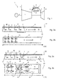
- Fig. 1 shows a gas turbine 1 with an impingement cooled combustor 4. It comprises a compressor 3, a combustor 4, and a turbine 5.
- Intake air 2 is compressed to compressed gas 11 by the compressor 3 and feed to the combustor via a plenum 20 to a combustor.
- Fuel 8 is burned with the compressed gas in the combustor 4 to generate a hot gas flow 19. The hot gas is expended in the turbine 5 generating mechanical work.
- the gas turbine system includes a generator 17 which is coupled to a shaft 6 of the gas turbine 1.
- the gas turbine 1 further comprises a cooling system for the turbine 5 and the combustor 4, which is not shown, as it is not the subject of this disclosure.
- Fig. 2a shows a cut through an impingement cooled wall arrangement 12 and Fig. 2b shows a top view of the impingement cooled wall arrangement 12 of Fig 2a .
- the impingement cooled wall arrangement 12 comprises a wall 7 which is exposed to a hot gas flow 19 on one side.
- a cooling sleeve 10 comprising apertures 14 for impingement cooling of the wall 7 is arranged at a distance above the wall 7.
- Compressed gas 11 is feed from the plenum 20 through apertures 13 and impinges on the wall 7. After the compressed gas 11 impinges on the wall 7 it flows as a cross flow 16 in the cooling flow path 15 formed by the wall 7 and the sleeve 10 towards the downstream end 28 of the cooling flow path 15.
- the hot gas flow 19 and cross flow 16 flow in the same direction parallel to each other towards the downstream end 28 of the cooling flow path 15.
- Fig. 2b shows a top view of the arrangement of Fig. 2a .
- the impingement cooled wall arrangement 12 is delimited to an upstream end and to both sides by a cooling field wall 27.
- Two rows of apertures 13 are arranged in parallel.
- the compressed gas 11 flows through the apertures 13 to form a cross flow 16.
- apertures for compressed gas injection on the wall 7 are arranged in an upstream section of the impingement cooled wall arrangement 12.
- the downstream section is only cooled by the cross flow 16.
- the length x of the cooling flow path starting from the upstream end is indicated below the Fig. 2b .
- FIG. 3a, 3b A first example of an impingement cooled wall arrangement according to the disclosure is shown in Fig. 3a, 3b, Fig. 3a, 3b is based on Fig. 2a, 2b and same elements are numbered identically.
- the number of first apertures 13 arranged in the direction of the cross flow is reduced compared to the arrangement of Fig. 2a, 2b .
- the arrangement shown in Fig. 3a, 3b has diverter 21 arranged downstream (in direction of the cross flow) of the group of first apertures 13.
- the flow diverter 21 shields a group of second apertures 14 from the cross flow 16 of the compressed gas introduced through the first apertures 13 and it around second apertures 14.
- compressed gas 11 introduced through the second apertures can impinge on the wall 7 without deflection by the cross flow originating from the first apertures 13.
- the deflector 21 has a U-formed shape with the two legs of the U extending in flow direction of the cross flow 16 around the second apertures 14. Due to the compressed gas 11 introduced through the second apertures 14 a cross flow or inner cross flow 16 i starts in the diverter 21.
- the first convective section 29 which is the region outside the diverter 21, in the region between the diverter 21, and the cooling field wall 27, or more precisely between the legs of the diverter 21 and the cooling field wall 27 in the section between the upstream and downstream end of the diverter 21, there is no impingement cooling.
- This section of the wall 7 is convectively cooled by the diverted cross flow.
- the outer cross flow 16o and the inner cross flow 16i merge. Differences in the flow velocity of the inner cross flow 16i and outer flow velocity 16o can lead to mixing losses, i.e. pressure losses.
- the resulting cross flow 16 of the inner and outer cross flow 16i, 16o cool the second convective section 31 which extends from the downstream end of the diverter 21 to the downstream end 28 of the impingement cooled wall arrangement 12.
- hot gas flow 19 is indicated as counter flow to the direction of the cross flow 16.
- Fig. 3c shows modification based on the example shown in Fig. 3b .
- the cooling arrangement has a plurality of diverters 21 without a separation of a cooling field wall. Also there is no cooling field wall defining an upstream end of the impingement cooled wall. At the upstream end further first apertures 13 are arranged. However, the compressed gas 11 introduced through the first two rows of first apertures 13 flows in the opposite direction of the cross flow 16 away from the diverter 21.
- the length x of the cooling flow path starting from the upstream end is indicated below the Fig. 3c . Here the starting point is the location where upstream of the first apertures 13 from which cross flow 16 flows towards the diverter 21.
- Fig. 4 shows the development the resulting heat transfer coefficient II over the length of the impingement cooled wall of Fig. 2a/2b and the heat transfer coefficient III of the impingement cooled wall with diverters of Fig. 3a/3b / 3c .
- the local peaks in cooling due to impingement of the compressed gas introduced through the apertures 13, 14 on the wall 7 are clearly indicated.
- the resulting heat transfer coefficient over the length of the impingement cooled wall is an average heat transfer coefficient over the width of the cooled wall section.
- the peaks are reduced due to the cross flow 16 over the length x.
- the heat transfer coefficient III at the first shielded aperture 14 as indicated by the dotted line is as high as for the very first aperture 13.
- Fig. 5a, 5b is based on Fig. 2a, 2b . It shows an impingement cooled wall arrangement with a diverter to shield a second aperture for impingement cooling and adapted cooling flow path height H.
- the cooling flow path height H is adapted to the local requirements for optimized cooling. In an upstream region upstream of the flow diverter 21 the flow path height H is biggest to keep the flow velocity of the cross flow low. In the region of the diverter 21 the flow path height is reduced to accelerate the cross flow guided around the flow diverter 21 through the first convective cooling section 29 (upstream and downstream end of this section is indicated by a chain-dotted line in Fig. 5b ).
- the legs of the diverter 21 are inclined towards each other at the downstream end. This inclination or convergence leads to a nozzle like geometry with reduction of the cross section at the outlet of the diverter 21, thus accelerating the inner cross flow 16i. At the same time the inclination leads to a diffusor like geometry of the downstream end of the first convective cooling section 29, thus decelerating the outer cross flow 16o.
- the inclination of the legs' downstream ends can be chosen to minimize the differences between the inner and outer cross flow 16i, 16o velocities at the downstream end of the diverter 21 thereby mitigating mixing losses.
- Fig. 6 shows the development the total pressure drop ⁇ p over the length x of an impingement cooled wall 7.
- the chain-dotted line III indicates the pressure loss for an embodiment like the one shown in Fig. 3 with a diverter 21 having straight legs and a constant channel height H.
- the dotted line VIII indicates the pressure loss for an embodiment with some pressure recovery like the one shown in Fig. 8 , e.g. with a diverter 21 having a constant channel height H and diverter legs which converge towards the downstream end of the diverter 21.
- the solid line V indicates the pressure loss for an embodiment with optimized pressure recovery and minimized mixing losses like the one shown in Fig. 5 .
- the channel height H is reduced around the diverter and increase again downstream of the diverter.
- the diverter legs converge towards the downstream end of the diverter 21.
- Fig. 7a, b is based on the example shown in Fig. 5a , b.
- additional cooling gas is introduced through injection holes 30 in the sleeve 10 at the downstream end of the diverter 21 in the region where the channel height H is increasing.
- balancing holes 23 are provided in the converging sections of the legs at the downstream end of the diverter 21. Depending on the static pressure distribution along the legs inside of the diverter relative to outside the diverter these balancing holes 23 allow injection of cooling gas from the inside of the diverter 21 into the boundary layer of the flow around the diverter 21, respectively allow boundary layer suction. Both measures can avoid flow separation at the downstream end of the diverter and can therefore reduce the pressure loss.
- Fig. 8a, b shows an impingement cooled wall arrangement with legs converging at the downstream end of the diverter 21.
- the converging end sections of the legs are made out of a porous material to allow for boundary layer suction of addition of cooling gas into the boundary layer on the downstream ends of the diverter legs.
- the impingement cooled wall arrangement shown in embodiments can be used for example in a gas turbine with can combustors.
- the can combustors are typically circumferentially distributed around the shaft 6 of the gas turbine and have a transition piece or transition section for the transition from a circular cross section of the combustion chamber to a cross section with a shape of a section of an annulus or practically rectangular flow cross section at the outlet, i.e. at the turbine inlet.
- the transition piece can be integrated into the duct or be a separate duct and the disclosed impingement cooled wall arrangement can equally be used for the duct guiding the hot gases in the transition piece.
- the impingement cooled wall arrangement can also be used for cooling of any other component like for example blade cooling.
- the arrangement of the flow diverters relative to the flow direction in the flow path can be modified.
- the flow diverters can for example be included to direction of the cross flow upstream of the diverter to cause secondary flows for increased heat transfer.
- the diverter can also have a fluid dynamically optimized contour like a blade profile.
- the disclosed impingement cooled wall arrangement and method for cooling can be used in gas turbines as well as in other machines or plants in which a wall is exposed to hot gas such as for example a furnace or a reactor.
Landscapes
- Engineering & Computer Science (AREA)
- Chemical & Material Sciences (AREA)
- Combustion & Propulsion (AREA)
- Mechanical Engineering (AREA)
- General Engineering & Computer Science (AREA)
- Turbine Rotor Nozzle Sealing (AREA)
Priority Applications (7)
| Application Number | Priority Date | Filing Date | Title |
|---|---|---|---|
| EP14171995.5A EP2955442A1 (fr) | 2014-06-11 | 2014-06-11 | Agencement de paroi refroidie par convection |
| EP15168544.3A EP2955443B1 (fr) | 2014-06-11 | 2015-05-20 | Agencement de paroi refroidi par impact |
| US14/732,070 US10060352B2 (en) | 2014-06-11 | 2015-06-05 | Impingement cooled wall arrangement |
| JP2015117430A JP2016006374A (ja) | 2014-06-11 | 2015-06-10 | インピンジメント冷却される壁配列 |
| KR1020150081752A KR20150142621A (ko) | 2014-06-11 | 2015-06-10 | 충돌 냉각식 벽 장치 |
| RU2015122395A RU2696830C2 (ru) | 2014-06-11 | 2015-06-10 | Устройство для инжекционного охлаждения стенки |
| CN201510318236.4A CN105275620B (zh) | 2014-06-11 | 2015-06-11 | 冲击冷却式壁组件、包括它的燃烧器和/或燃气涡轮及冲击冷却方法 |
Applications Claiming Priority (1)
| Application Number | Priority Date | Filing Date | Title |
|---|---|---|---|
| EP14171995.5A EP2955442A1 (fr) | 2014-06-11 | 2014-06-11 | Agencement de paroi refroidie par convection |
Publications (1)
| Publication Number | Publication Date |
|---|---|
| EP2955442A1 true EP2955442A1 (fr) | 2015-12-16 |
Family
ID=50942104
Family Applications (2)
| Application Number | Title | Priority Date | Filing Date |
|---|---|---|---|
| EP14171995.5A Withdrawn EP2955442A1 (fr) | 2014-06-11 | 2014-06-11 | Agencement de paroi refroidie par convection |
| EP15168544.3A Active EP2955443B1 (fr) | 2014-06-11 | 2015-05-20 | Agencement de paroi refroidi par impact |
Family Applications After (1)
| Application Number | Title | Priority Date | Filing Date |
|---|---|---|---|
| EP15168544.3A Active EP2955443B1 (fr) | 2014-06-11 | 2015-05-20 | Agencement de paroi refroidi par impact |
Country Status (6)
| Country | Link |
|---|---|
| US (1) | US10060352B2 (fr) |
| EP (2) | EP2955442A1 (fr) |
| JP (1) | JP2016006374A (fr) |
| KR (1) | KR20150142621A (fr) |
| CN (1) | CN105275620B (fr) |
| RU (1) | RU2696830C2 (fr) |
Cited By (1)
| Publication number | Priority date | Publication date | Assignee | Title |
|---|---|---|---|---|
| EP3485213B1 (fr) * | 2016-07-14 | 2023-01-04 | General Electric Company | Échangeur de chaleur à entraînement |
Families Citing this family (4)
| Publication number | Priority date | Publication date | Assignee | Title |
|---|---|---|---|---|
| EP3205937B1 (fr) | 2016-02-09 | 2021-03-31 | Ansaldo Energia IP UK Limited | Agencement de paroi refroidie par impact |
| JP6956779B2 (ja) * | 2016-08-30 | 2021-11-02 | シーメンス アクチエンゲゼルシヤフトSiemens Aktiengesellschaft | ガスタービン用のインピンジメント冷却特徴 |
| US11933223B2 (en) * | 2019-04-18 | 2024-03-19 | Rtx Corporation | Integrated additive fuel injectors for attritable engines |
| CN112228905B (zh) * | 2020-10-13 | 2022-01-21 | 西北工业大学 | 一种可抑制超临界流体流量分配偏差的通道结构 |
Citations (5)
| Publication number | Priority date | Publication date | Assignee | Title |
|---|---|---|---|---|
| US4719748A (en) | 1985-05-14 | 1988-01-19 | General Electric Company | Impingement cooled transition duct |
| US5605046A (en) * | 1995-10-26 | 1997-02-25 | Liang; George P. | Cooled liner apparatus |
| EP1188902A1 (fr) * | 2000-09-14 | 2002-03-20 | Siemens Aktiengesellschaft | Paroi refroidie par jet |
| WO2011020485A1 (fr) * | 2009-08-20 | 2011-02-24 | Siemens Aktiengesellschaft | Dispositifs de blocage d'écoulement transversal dans une fente de refroidissement par impact de jets d'une turbine à gaz |
| CA2859154A1 (fr) * | 2011-12-15 | 2013-06-20 | Ihi Corporation | Mecanisme de refroidissement par contact, aube de turbine et chambre de combustion |
Family Cites Families (19)
| Publication number | Priority date | Publication date | Assignee | Title |
|---|---|---|---|---|
| SU1126027A1 (ru) * | 1983-08-26 | 1985-06-07 | Производственное Объединение Турбостроения "Ленинградский Металлический Завод" | Цилиндр паровой турбины |
| US4887425A (en) | 1988-03-18 | 1989-12-19 | General Electric Company | Fuel spraybar |
| FR2689567B1 (fr) | 1992-04-01 | 1994-05-27 | Snecma | Injecteur de carburant pour chambre de post-combustion d'une turbomachine. |
| GB2266579B (en) * | 1992-04-16 | 1995-12-20 | Baj Ltd | Gas operated ejection system |
| JP3110227B2 (ja) * | 1993-11-22 | 2000-11-20 | 株式会社東芝 | タービン冷却翼 |
| FR2873411B1 (fr) | 2004-07-21 | 2009-08-21 | Snecma Moteurs Sa | Turboreacteur avec des moyens de protection pour un dispositif d'injection de carburant, dispositif d'injection et tole de protection pour le turboreacteur |
| US7373778B2 (en) * | 2004-08-26 | 2008-05-20 | General Electric Company | Combustor cooling with angled segmented surfaces |
| JP2008521437A (ja) * | 2004-11-30 | 2008-06-26 | マックスサイト インコーポレーティッド | コンピュータ化されたエレクトロポレーション |
| US8387396B2 (en) | 2007-01-09 | 2013-03-05 | General Electric Company | Airfoil, sleeve, and method for assembling a combustor assembly |
| US8281600B2 (en) * | 2007-01-09 | 2012-10-09 | General Electric Company | Thimble, sleeve, and method for cooling a combustor assembly |
| US8127553B2 (en) * | 2007-03-01 | 2012-03-06 | Solar Turbines Inc. | Zero-cross-flow impingement via an array of differing length, extended ports |
| RU2403491C2 (ru) * | 2008-03-26 | 2010-11-10 | Федеральное государственное унитарное предприятие "Центральный институт авиационного моторостроения имени П.И. Баранова" | Термосиловая охлаждаемая конструкция стенки элемента высокотемпературного воздушно-газового тракта |
| US8166764B2 (en) * | 2008-07-21 | 2012-05-01 | United Technologies Corporation | Flow sleeve impingement cooling using a plenum ring |
| WO2011054760A1 (fr) | 2009-11-07 | 2011-05-12 | Alstom Technology Ltd | Système de refroidissement permettant d'accroître le rendement d'une turbine à gaz |
| US20130081401A1 (en) * | 2011-09-30 | 2013-04-04 | Solar Turbines Incorporated | Impingement cooling of combustor liners |
| US9243801B2 (en) * | 2012-06-07 | 2016-01-26 | United Technologies Corporation | Combustor liner with improved film cooling |
| US20130333388A1 (en) * | 2012-06-13 | 2013-12-19 | General Electric Company | Combustor liner cooling assembly for a gas turbine system |
| KR101556532B1 (ko) * | 2014-01-16 | 2015-10-01 | 두산중공업 주식회사 | 냉각슬리브를 포함하는 라이너, 플로우슬리브 및 가스터빈연소기 |
| US10113745B2 (en) * | 2015-03-26 | 2018-10-30 | Ansaldo Energia Switzerland AG | Flow sleeve deflector for use in gas turbine combustor |
-
2014
- 2014-06-11 EP EP14171995.5A patent/EP2955442A1/fr not_active Withdrawn
-
2015
- 2015-05-20 EP EP15168544.3A patent/EP2955443B1/fr active Active
- 2015-06-05 US US14/732,070 patent/US10060352B2/en active Active
- 2015-06-10 JP JP2015117430A patent/JP2016006374A/ja active Pending
- 2015-06-10 KR KR1020150081752A patent/KR20150142621A/ko unknown
- 2015-06-10 RU RU2015122395A patent/RU2696830C2/ru active
- 2015-06-11 CN CN201510318236.4A patent/CN105275620B/zh active Active
Patent Citations (5)
| Publication number | Priority date | Publication date | Assignee | Title |
|---|---|---|---|---|
| US4719748A (en) | 1985-05-14 | 1988-01-19 | General Electric Company | Impingement cooled transition duct |
| US5605046A (en) * | 1995-10-26 | 1997-02-25 | Liang; George P. | Cooled liner apparatus |
| EP1188902A1 (fr) * | 2000-09-14 | 2002-03-20 | Siemens Aktiengesellschaft | Paroi refroidie par jet |
| WO2011020485A1 (fr) * | 2009-08-20 | 2011-02-24 | Siemens Aktiengesellschaft | Dispositifs de blocage d'écoulement transversal dans une fente de refroidissement par impact de jets d'une turbine à gaz |
| CA2859154A1 (fr) * | 2011-12-15 | 2013-06-20 | Ihi Corporation | Mecanisme de refroidissement par contact, aube de turbine et chambre de combustion |
Cited By (1)
| Publication number | Priority date | Publication date | Assignee | Title |
|---|---|---|---|---|
| EP3485213B1 (fr) * | 2016-07-14 | 2023-01-04 | General Electric Company | Échangeur de chaleur à entraînement |
Also Published As
| Publication number | Publication date |
|---|---|
| US20150361889A1 (en) | 2015-12-17 |
| RU2015122395A3 (fr) | 2018-12-18 |
| RU2015122395A (ru) | 2016-12-27 |
| CN105275620A (zh) | 2016-01-27 |
| RU2696830C2 (ru) | 2019-08-06 |
| KR20150142621A (ko) | 2015-12-22 |
| EP2955443B1 (fr) | 2018-07-04 |
| JP2016006374A (ja) | 2016-01-14 |
| US10060352B2 (en) | 2018-08-28 |
| EP2955443A1 (fr) | 2015-12-16 |
| CN105275620B (zh) | 2019-01-04 |
Similar Documents
| Publication | Publication Date | Title |
|---|---|---|
| US9970355B2 (en) | Impingement cooling arrangement | |
| JP6952460B2 (ja) | ガスタービンの燃焼システムにおける段階的な燃料および空気噴射 | |
| EP2955443B1 (fr) | Agencement de paroi refroidi par impact | |
| JP2016099108A (ja) | 多段燃焼を備えるガスタービンのための燃料ランス冷却 | |
| US7118326B2 (en) | Cooled gas turbine vane | |
| US10393022B2 (en) | Cooled component having effusion cooling apertures | |
| KR100570149B1 (ko) | 가스 터빈 스팀 냉각 베인 | |
| US20090047136A1 (en) | Angled tripped airfoil peanut cavity | |
| EP2921779B1 (fr) | Chambre de combustion avec manchon de refroidissement | |
| EP2562479A2 (fr) | Éléments muraux pour moteurs à turbine à gaz | |
| JP2008169837A (ja) | 翼形、スリーブ及び燃焼器アセンブリの組立方法 | |
| US9512782B2 (en) | Gas turbine engine end-wall component | |
| US20150132117A1 (en) | Gas turbine engine ducting arrangement having discrete insert | |
| EP2966356B1 (fr) | Agencement de combustion séquentielle avec un mélangeur | |
| KR20160064019A (ko) | 연소기 터빈 계면용 프레임 세그먼트 | |
| KR20150063949A (ko) | 인접 벽 마이크로회로 에지 냉각 수단을 구비한 터빈 블레이드 | |
| JP2014009937A (ja) | ガスタービン用移行ダクト | |
| EP3205937B1 (fr) | Agencement de paroi refroidie par impact | |
| US20170122112A1 (en) | Controlling cooling flow in a cooled turbine vane or blade using an impingement tube | |
| WO2019002274A1 (fr) | Composant de turbomachine et procédé de fabrication du composant de turbomachine | |
| JP5614954B2 (ja) | 燃焼器とタービン部との連通構造、および、ガスタービン | |
| CN113250758B (zh) | 涡轮喷嘴部段和包括这种涡轮喷嘴部段的涡轮喷嘴 |
Legal Events
| Date | Code | Title | Description |
|---|---|---|---|
| PUAI | Public reference made under article 153(3) epc to a published international application that has entered the european phase |
Free format text: ORIGINAL CODE: 0009012 |
|
| 17P | Request for examination filed |
Effective date: 20140611 |
|
| AK | Designated contracting states |
Kind code of ref document: A1 Designated state(s): AL AT BE BG CH CY CZ DE DK EE ES FI FR GB GR HR HU IE IS IT LI LT LU LV MC MK MT NL NO PL PT RO RS SE SI SK SM TR |
|
| AX | Request for extension of the european patent |
Extension state: BA ME |
|
| STAA | Information on the status of an ep patent application or granted ep patent |
Free format text: STATUS: THE APPLICATION IS DEEMED TO BE WITHDRAWN |
|
| 18D | Application deemed to be withdrawn |
Effective date: 20160617 |