EP2562479A2 - Éléments muraux pour moteurs à turbine à gaz - Google Patents
Éléments muraux pour moteurs à turbine à gaz Download PDFInfo
- Publication number
- EP2562479A2 EP2562479A2 EP12180538A EP12180538A EP2562479A2 EP 2562479 A2 EP2562479 A2 EP 2562479A2 EP 12180538 A EP12180538 A EP 12180538A EP 12180538 A EP12180538 A EP 12180538A EP 2562479 A2 EP2562479 A2 EP 2562479A2
- Authority
- EP
- European Patent Office
- Prior art keywords
- wall
- protrusion
- cooling fluid
- double
- gas turbine
- Prior art date
- Legal status (The legal status is an assumption and is not a legal conclusion. Google has not performed a legal analysis and makes no representation as to the accuracy of the status listed.)
- Granted
Links
- 238000001816 cooling Methods 0.000 claims abstract description 77
- 239000012809 cooling fluid Substances 0.000 claims abstract description 75
- 238000000034 method Methods 0.000 claims description 11
- 238000011144 upstream manufacturing Methods 0.000 claims description 9
- 239000012530 fluid Substances 0.000 claims description 8
- 239000007789 gas Substances 0.000 description 18
- 238000002485 combustion reaction Methods 0.000 description 8
- 239000000446 fuel Substances 0.000 description 6
- 230000001141 propulsive effect Effects 0.000 description 5
- 238000004519 manufacturing process Methods 0.000 description 4
- 238000005201 scrubbing Methods 0.000 description 4
- 230000001154 acute effect Effects 0.000 description 2
- 230000008021 deposition Effects 0.000 description 2
- 239000000203 mixture Substances 0.000 description 2
- 238000000926 separation method Methods 0.000 description 2
- 238000013459 approach Methods 0.000 description 1
- 230000006835 compression Effects 0.000 description 1
- 238000007906 compression Methods 0.000 description 1
- 230000003247 decreasing effect Effects 0.000 description 1
- 230000000694 effects Effects 0.000 description 1
- 239000007921 spray Substances 0.000 description 1
- 230000002889 sympathetic effect Effects 0.000 description 1
Images


Classifications
-
- F—MECHANICAL ENGINEERING; LIGHTING; HEATING; WEAPONS; BLASTING
- F23—COMBUSTION APPARATUS; COMBUSTION PROCESSES
- F23R—GENERATING COMBUSTION PRODUCTS OF HIGH PRESSURE OR HIGH VELOCITY, e.g. GAS-TURBINE COMBUSTION CHAMBERS
- F23R3/00—Continuous combustion chambers using liquid or gaseous fuel
- F23R3/002—Wall structures
-
- F—MECHANICAL ENGINEERING; LIGHTING; HEATING; WEAPONS; BLASTING
- F23—COMBUSTION APPARATUS; COMBUSTION PROCESSES
- F23R—GENERATING COMBUSTION PRODUCTS OF HIGH PRESSURE OR HIGH VELOCITY, e.g. GAS-TURBINE COMBUSTION CHAMBERS
- F23R2900/00—Special features of, or arrangements for continuous combustion chambers; Combustion processes therefor
- F23R2900/03041—Effusion cooled combustion chamber walls or domes
-
- F—MECHANICAL ENGINEERING; LIGHTING; HEATING; WEAPONS; BLASTING
- F23—COMBUSTION APPARATUS; COMBUSTION PROCESSES
- F23R—GENERATING COMBUSTION PRODUCTS OF HIGH PRESSURE OR HIGH VELOCITY, e.g. GAS-TURBINE COMBUSTION CHAMBERS
- F23R2900/00—Special features of, or arrangements for continuous combustion chambers; Combustion processes therefor
- F23R2900/03044—Impingement cooled combustion chamber walls or subassemblies
-
- Y—GENERAL TAGGING OF NEW TECHNOLOGICAL DEVELOPMENTS; GENERAL TAGGING OF CROSS-SECTIONAL TECHNOLOGIES SPANNING OVER SEVERAL SECTIONS OF THE IPC; TECHNICAL SUBJECTS COVERED BY FORMER USPC CROSS-REFERENCE ART COLLECTIONS [XRACs] AND DIGESTS
- Y02—TECHNOLOGIES OR APPLICATIONS FOR MITIGATION OR ADAPTATION AGAINST CLIMATE CHANGE
- Y02T—CLIMATE CHANGE MITIGATION TECHNOLOGIES RELATED TO TRANSPORTATION
- Y02T50/00—Aeronautics or air transport
- Y02T50/60—Efficient propulsion technologies, e.g. for aircraft
Definitions
- This invention relates to cooling in gas turbine engines, and in particular to cooling wall elements for use in wall structures of components, such as combustors and turbines, of gas turbine engines.
- Combustors of gas turbine engines can be constructed with a double-wall (also known as a double-skin) structure.
- a double-wall also known as a double-skin
- an annular combustor may have radially inner and outer walls, each having a double-wall structure.
- Other elements of a gas turbine engine that are exposed to high temperature can be similarly constructed with a double-wall structure.
- Such a double-wall structure has an external wall and an internal wall.
- the internal wall is usually formed of a plurality of tiles or other similar wall elements.
- the internal wall has a surface that faces the hot fluid, for example the combustion fluids inside the combustion chamber.
- cooling methods involve passing cooling air through holes in the external wall such that it directly impinges on the internal wall. This may be referred to as impingement cooling. Further cooling may be provided through convection by passing the cooling air between the internal and external walls. Still further cooling may be provided by passing the cooling air out through holes in the internal wall to provide a cooling film on the surface of the internal wall that faces the hot fluid.
- a significant amount of cooling airflow is used to cool such a double-wall structure using current methods.
- the airflow that is used for cooling could otherwise be used to provide thrust and thus to improve propulsive efficiency of the engine.
- An object of the present invention is therefore to provide an improved cooling arrangement to reduce the amount of cooling airflow required for a given level of cooling.
- a gas turbine engine component comprising a double-wall structure.
- the double-wall structure comprises: a first wall having a first surface and a second surface; and a second wall spaced apart from the first wall such that the second surface of the first wall faces the second wall, the second wall comprising at least one cooling fluid orifice configured to direct cooling fluid in the direction of the first wall.
- the double wall structure also comprises a protrusion extending from a base on the second surface of the first wall to a tip. The protrusion is located such that, in use, cooling fluid from a respective cooling fluid orifice is directed towards the tip thereof.
- the height of the protrusion above the second surface may be at least 25% of the distance between the first wall and the second wall.
- the first surface (which may be referred to as the outer surface) of the first wall (which may be referred to as the internal wall) may, in use, be exposed to high temperatures, for example the inside of a combustor.
- Providing a protrusion on the second surface (which may be referred to as the inner surface) of the first wall and directing cooling fluid towards and over it may increase the heat transfer away from the first wall. This may increase the efficiency of the cooling flow, and thus decrease the amount of cooling fluid required to obtain a desired amount of cooling.
- the protrusion may have a generally tapered shape from the base to the tip.
- the cooling fluid may be caused to diverge over the protrusion as it passes from the tip to the base. In this way, heat is transferred from the protrusion to the cooling fluid as it passes over the protrusion, and the direction of the cooling fluid can be changed in a controlled manner, for example so as to become more aligned with the surface from which the protrusion extends.
- the double-wall structure may comprise a plurality of protrusions, each protrusion corresponding to a respective cooling fluid orifice.
- substantially all cooling fluid that is directed towards the tip of any given protrusion may be from its corresponding respective cooling fluid orifice.
- substantially all of the cooling fluid supplied to any given protrusion is from a single cooling fluid orifice.
- each orifice may supply cooling fluid to more than one protrusion, such that the number of protrusions may be greater than the number of cooling fluid orifices.
- the double-wall structure may comprise a plurality of cooling fluid orifices, each cooling fluid orifice corresponding to a single respective protrusion.
- substantially all cooling fluid from any given cooling fluid orifice may be directed towards its corresponding single respective protrusion. This means that substantially all of the cooling fluid supplied by any given cooling fluid orifice is supplied to a single protrusion.
- each orifice may only supply cooling fluid to one protrusion, although each protrusion may be supplied with cooling fluid by more than one orifice, such that the number of protrusions may be less than the number of cooling fluid orifices.
- the double-wall structure may comprise a trough.
- the trough may extend around at least a part of the perimeter of the base of each protrusion.
- the trough may be formed in the second surface of the first wall. Such a trough may help to further enhance heat transfer from the first wall to the cooling fluid, for example by causing a "scrubbing" vortex to be formed therein.
- Each protrusion may have a major axis that is aligned with a major axis of a corresponding cooling fluid orifice. This can help to ensure that the cooling fluid is delivered from the cooling fluid orifice to the protrusion in the desired way.
- Each protrusion may have a major axis that is parallel to and offset from a major axis of a corresponding cooling fluid orifice.
- the or each protrusion may be axisymmetric about a major axis that is substantially normal to the second surface of the first wall, from which the protrusion extends.
- Cross sections taken through the or each protrusion in any plane perpendicular to the major axis may be circular.
- Each protrusion may skewed from base to tip in a direction that is parallel to the principal rotational axis of the gas turbine engine when assembled.
- the direction in which the protrusion is skewed may be the upstream direction of the fluid flow through the gas turbine engine when in use
- each protrusion may have a major axis that is parallel to the second surface of the first wall.
- it may be particularly advantageous to have more than one cooling fluid orifice arranged to supply cooling fluid to a single protrusion, so as to ensure appropriate cooling fluid (in terms of, for example, flow rate and distribution) is directed to each protrusion.
- the or each cooling fluid orifice may be a feed hole in the second wall.
- the cooling fluid may be cooling air, for example taken from a compressor, such as the high pressure compressor, or from a bypass flow or secondary flow.
- the cooling air may, in operation, flow along or around the surface of the second wall (which may be referred to as the external wall) that faces away from the first wall before passing through the feed hole.
- the tip of the or each protrusion may extend at least partially into a respective feed hole in the second wall. This arrangement may help to provide the desired flow pattern over the protrusion(s).
- Each protrusion may have a major longitudinal axis, and the spacing between neighbouring longitudinal axes may be at least 50% of the spacing between the first wall and the second wall. This feature may help to ensure that the protrusions are spaced to provide optimum heat transfer away from the first wall, for example as the cooling fluid flows along the surfaces of the protrusions. For example, it may reduce any impact of thermal boundary layers of neighbouring protrusions interacting with each other.
- a combustor comprising a gas turbine engine component comprising a double-wall structure as described herein.
- the first surface of the first wall may face the inside of the combustor.
- the double-wall structure may thus substantially reduce and/or minimize the amount of cooling air required to cool the combustor walls.
- an aerofoil comprising a gas turbine engine component comprising a double-wall structure according as described herein.
- the first surface of the first wall may face a working fluid. This may substantially reduce and/or minimize the amount of cooling air required to cool such a component.
- a nozzle comprising a gas turbine engine component comprising a double-wall structure according as described herein.
- a method of manufacturing a gas turbine engine component comprising a double-wall structure as described herein, wherein at least the protrusions are manufactured using direct laser deposition.
- Such a manufacturing technique may, for example, assist in accurate alignment of features as required, for example alignment of the protrusions with the cooling fluid orifices.
- a method of cooling a double-wall structure comprising providing a protrusion on a second surface of the first wall, the protrusion extending from a base in the direction of the second wall to a tip.
- the height of the protrusion above the second surface may be at least 25% of the (local minimum) distance between the first wall and the second wall.
- the method comprises supplying a cooling fluid flow to the protrusion from a respective cooling fluid orifice, the cooling fluid flow being directed towards the tip of the protrusion.
- a method of cooling a double-wall structure comprising supplying a cooling fluid flow to a protrusion from a respective cooling fluid orifice.
- the protrusion is provided on a second surface of the first wall.
- the protrusion extends from a base in the direction of the second wall to a tip, the cooling fluid flow being directed towards the tip of the protrusion.
- the cooling fluid flows over the surface of the protrusion from the tip to the base, thereby removing heat from the protrusion.
- the cooling fluid orifice is a hole in the second wall, and the method comprises supplying cooling fluid flow through the hole.
- a ducted fan gas turbine engine generally indicated at 10 has a principal and rotational axis X-X.
- the engine 10 comprises, in axial flow series, an air intake 11, a propulsive fan 12, an intermediate pressure compressor 13, a high-pressure compressor 14, combustion equipment 15, a high-pressure turbine 16, an intermediate pressure turbine 17, a low-pressure turbine 18 and a core engine exhaust nozzle 19.
- a nacelle 21 generally surrounds the engine 10 and defines the intake 12, a bypass duct 22 and a bypass exhaust nozzle 23.
- the gas turbine engine 10 works in a conventional manner so that air entering the intake 11 is accelerated by the fan 12 to produce two air flows: a first air flow A into the intermediate pressure compressor 14 and a second air flow B which passes through the bypass duct 22 to provide propulsive thrust.
- the intermediate pressure compressor 13 compresses the air flow A directed into it before delivering that air to the high pressure compressor 14 where further compression takes place.
- the compressed air exhausted from the high-pressure compressor 14 is directed into the combustion equipment 15 where it is mixed with fuel and the mixture combusted.
- the resultant hot combustion products then expand through, and thereby drive, the high, intermediate and low-pressure turbines 16, 17, 18 before being exhausted through the nozzle 19 to provide additional propulsive thrust.
- the high, intermediate and low-pressure turbines 16, 17, 18 respectively drive the high and intermediate pressure compressors 14, 13 and the fan 12 by suitable interconnecting shafts.
- This ducted gas turbine engine is one of many engines that the double-wall structure can be applied to and is not intended to be limiting. Purely by way of further example, other engines that the double-wall structure could be applied to include turbofan, turbojet, turboshaft, ramjet (and variants thereof) and nozzles thereof.
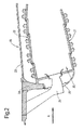
- the combustor 15 comprises an annular combustion chamber 20 having radially inner and outer double-wall structures 21 and 22 respectively.
- the combustor 15 is secured to a wall 23 by a plurality of pins 24 (only one of which is shown).
- Fuel is directed into the chamber 20 through a number of fuel nozzles 25 located at the upstream end 26 of the chamber 20.
- the fuel nozzles are circumferentially spaced around the engine 10 and serve to spray fuel into air (flow A) derived from the high-pressure compressor 14. The resultant fuel/air mixture is then combusted within the chamber 20.
- the combustion process which takes place within the chamber 20, naturally generates a large amount of heat. It is necessary therefore to arrange the inner and outer wall structures 21 and 22 such that they are capable of withstanding the heat.
- conventional radially inner and outer double-wall structures 21 and 22 each comprise an external wall in the form of a liner 27 and an internal wall 28.
- Figure 3 shows an outer double-wall structure 22.
- the terms 'internal' and 'external' are with respect to the combustion chamber 20.
- the internal wall 28 is made up of a plurality of discrete wall elements in the form of tiles 29A and 29B.
- Each of the tiles 29A, 29B has circumferentially extending edges 30 and 31, and the tiles are positioned adjacent each other, such that the edges 30 and 31 of adjacent tiles 29A, 29B overlap each other. Alternatively, the edges 30, 31 of adjacent tiles can abut each other.
- the circumferentially extending edges 30 and 31 are spaced from the liner 27 to define therebetween a space 38 for the flow of cooling fluid in the form of cooling air.
- Conventional securing means in the form of a plurality of threaded plugs extend from the base portions of the tiles 29A, 29B through apertures in the outer wall 27. Nuts are screwed onto the plugs to secure the tiles 29A, 29B to the external wall 27.
- Feed holes 42 are provided in the liner 27 to permit air from the high pressure compressor 14 to pass into the space 38 as illustrated by the arrows 44. Air entering the space will pass forwards and backwards (with respect to the main airflow A through the engine) as illustrated by the arrows 46A and 46B. At the edges 30, 31 of the tiles 29A, 29B the air will pass over the inner surface 41 of an adjacent tile 29B. For forward flowing air 46B, the path is simply over the inner hot surface 41 of an adjacent downstream tile 29B which will be offset outwardly as illustrated in the figure. For backwards flowing cooling air 46B, the air will turn 180°- to pass in a downstream direction with the air from the adjacent upstream tile 29A, 29B.
- This conventional configuration uses a significant amount of cooling airflow that could otherwise be used to improve propulsive efficiency of the engine.
- the point 48 at which the cooling air 44 entering through the feed holes 42 impinges on the inner surface 41 of the internal wall 28 may be a particular source of loss in the conventional configuration. For example turning the cooling flow through approximately 90 degrees at the point of impingement is relatively uncontrolled in the conventional configuration. This may lead to flow turbulence and/or loss in available cooling potential of the flow at the impingement point 48.
- An object of the present invention is therefore to provide more efficient cooling of the internal wall 28.
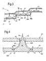
- a double-wall structure 100 according to an embodiment is shown in cross section. Some of the features of the double-wall structure 100 of Figure 4 are common to the conventional double-wall structure 22 described above in relation to Figure 3 , and so the same reference numerals are used where appropriate.
- the external wall 27 and feed hole 42 shown in Figure 4 are substantially the same as those shown in Figure 3 .
- a part of the internal wall 28 is also shown in Figure 4 , and this is at least in part different to that of Figure 3 , as described below.
- the internal wall 28 may comprise distinct tiles in a similar general arrangement to the tiles 29A, 29B described in relation to Figure 4 .
- other arrangements of internal wall 28 may also be in accordance with the invention, for example an arrangement in which the internal wall is continuous in the axial direction.
- the internal wall 28 of the double-wall structure 100 has a protrusion 50 extending therefrom.
- the protrusion 50 extends towards the external wall 27.
- the protrusion 50 extends towards the feed hole (or cooling fluid orifice) 42 in the external wall 27.
- the protrusion 50 has a base 52 that is located on the internal wall 28. The protrusion 50 extends from the base (or base portion) 52 to a tip (or tip portion) 54.
- cooling air 44 exits the feed hole 42 towards the tip 54 of the protrusion 50.
- the cooling air 44 may be bled from the HP compressor, for example from the exit of the compressor.
- the cooling air 44 may be provided by any other suitable source, such as a dedicated cooling feed.
- the cooling air 44 may be said to impinge on the tip 54 of the protrusion 50.
- the protrusion 50 of the embodiment shown in Figure 4 has a generally tapered shape from base 52 to tip 54.
- the protrusion 50 may be said to have a generally divergent shape from tip 54 to base 52.
- the cooling air follows the external shape of the protrusion 50 as it moves from the tip 54 to the base 52. This helps to improve heat transfer from the internal wall 28. Without being bound by any particular theory, the improved heat transfer may result from one or more than one effect, as described below with particular reference to Figures 4 and 5 .
- Figure 5 shows a cross section through an isometric view of the double-wall structure 100 shown in Figure 4 .
- the cooling air directed towards the tip 54 of the protrusion 50 follows the divergent shape of the sidewalls 56 along flow path 45A and 45B. This means that heat is transferred away from the protrusion 50, and thus away from the internal wall 28, along the length of the sidewall(s) 56 by the cooling air 45A and 45B.
- the arrows 45A and 45B in Figures 4 and 5 represent a continuous surface of cooling air flowing over the protrusion 50.
- the protrusion 50 therefore may be seen as increasing the surface area of the internal wall 28 that the cooling air flows over (or "scrubs"). This in itself may improve the efficiency of the heat transfer compared with the conventional impingement arrangement shown in Figure 3 , in which the cooling flow impinges directly on the inner surface 41 of the internal wall 28, by providing a greater surface area for cooling.
- an additional or alternative improvement in cooling may result from the protrusion 50 acting to redirect the cooling flow 44 in a controlled manner.
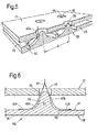
- the protrusion 50 may redirect the flow from a direction 44 that is substantially perpendicular to the internal wall 28 to a direction that is substantially parallel to the internal wall 28 (which may be referred to as a lateral direction) in a controlled (and thus more efficient) manner. This may be a feature of all embodiments, but may be particularly advantageous with regard to the embodiment shown in Figure 6 .
- the Figure 6 embodiment is substantially the same as the Figure 4 embodiment, other than in that it does not have the trough 60 (described in greater detail below) at the base of the protrusion 50.
- the redirected flow 43A/43B can then remove heat efficiently via convection from the inner surface 41 of the internal wall 28.
- the protrusion 50 has a trough (which may be referred to as a recess or channel) 60 formed at its base 52.
- the trough 60 may be formed around all of the base 52 (so as to form a closed loop around the protrusion 50), or around a part of the base 52.
- Such a trough 60 may be formed around at least a part of the base 52 of the protrusion 50 regardless of the shape of the protrusion 50.
- the trough 60 may act to further improve heat transfer from the internal wall 28 to the cooling air. As shown in Figure 4 , the trough 60 may generate a vortex (or recirculation) 47 therein. This vortex 47 removes heat from the internal wall 28 by generating high velocity cooling air flow on the surfaces of the trough 60. This high velocity cooling air flow may be said to "scrub" the surfaces of the trough 60, and as such the vortex 47 may be referred to as a "scrubbing vortex".
- the cross section of the trough 60 is shown in the embodiment of Figures 4 and 5 as having perpendicular corners.
- the base 52 of this embodiment is also shown to be lower (i.e. closer to the outer surface 39) than the inner surface 41. This may help to generate and/or strengthen the scrubbing vortex 47.
- any other suitable shape could be used for the trough 60.
- the base 52 of the protrusion 50 could be the same height above the outer surface 39 as the rest of the inner surface 41.
- the depth of the base 62 of the trough 60 below the inner surface 41 of the internal wall 28, and the width of the trough 60, may be chosen to maximize that heat transfer to the scrubbing vortex 47.
- the depth and width of the trough 60 may be chosen to avoid the vortex (or vortices) 47 breaking up and losing energy through turbulent dissipation.
- the depth of the base 62 of the trough 60 below the inner surface 41 of the internal wall 28 may be in the range of from 5% to 50%, for example 10% to 40%, for example 15%to 25% of the distance w between the internal wall 28 and the external wall 27.
- the depth of the trough 60 may be outside these ranges in some arrangements.
- the embodiment shown in Figure 4 is duplicated in Figure 7 , but with some of the reference numerals and flow paths removed and with dimensional labels added.
- the protrusion 50 shown in the embodiment of Figures 4 and 5 is axisymmetric about an axis 200.
- the protrusion 50 of this embodiment is circular in cross sections taken perpendicular to the axis 200 along the length of the axis.
- the diameters of the circular cross sections increase from the tip 54 to the base 52.
- the rate at which the diameters increase along the length of the axis 200 increases towards the base 52 of the protrusion shown in Figures 4 and 5 .
- protrusions are also in accordance with embodiments.
- other axisymmetric shapes may be used for the protrusion 50.
- shapes with 2, 3, 4, 5 or more than 5 axes of symmetry may be used.
- elongate shapes which have a major axis aligned with the inner surface 41 of the internal wall 28 may be used.
- Such an elongate shape may have a cross-section in the plane of that of Figures 4 and 5 that is substantially the same as that shown in Figures 4 or 5 , but with a longitudinal axis stretching into the plane of the paper in the view shown in Figure 4 , rather than being axisymmetric.
- FIG. 8 An example of an alternative shape of protrusion 50 is shown in Figure 8 .
- the protrusion 50 in Figure 8 is shaped to make effective use of cooling air 44A that flows (or has a flow component, for example a substantial flow component) parallel to the external wall 27 before flowing through the feed hole 42.
- the cooling air 44A may be said to have a component in the axial direction (or the downstream direction) of the engine as it approaches the feed hole 42. This means that the flow passing through the feed hole 42 may also have an axial component, i.e. it may not flow parallel to the feed hole axis.
- the protrusion 50 may be shaped such that, in cross section in a plane perpendicular to the internal wall 28 and parallel to the axial direction (i.e. in the cross section shown in Figure 8 ), the wall length from the tip 54 to the base 52 is greater in the downstream flow direction (i.e. wall length 56A) than in the upstream flow direction (i.e. wall length 56B). This means that the tip of the protrusion 50 may be skewed towards the upstream direction relative to the cooling flow 44A before the cooling flow 44A passes through the feed hole 42 (or relative to the main flow through the engine 10).
- the centroid of cross sections taken perpendicular to the (local) surface normal of the inner surface 41 may prescribe a path that has a component in the upstream (axial) direction as it moves from the base 52 to the tip 54 of the protrusion 50.
- the centroid path 300 (illustrated in Figure 8 ) may have a decreasing upstream (axial) component as it moves from the base 52 to the tip 54.
- the centroid path 300 may have an increasing radial component as it moves from the base 52 to the tip 54.
- this may mean the distance between equivalent points (in terms of the distance above the inner surface 41) on the centroid path 300 of neighbouring skewed protrusions.
- any suitable shape could be used for the cross sections taken perpendicular to the (local) surface normal of the inner surface 41 for the skewed protrusion 50 shown in Figure 8 .
- these cross sectional shapes could be circular, ovoid, or any other shape described herein in relation to other embodiments.
- Skewing the protrusion 50 may help to further improve cooling.
- the convection from the downstream side 56A of the protrusion may be improved due to the shape being more sympathetic (or aligned) with the oncoming flow 44A, which may have an axial component. This may mean that the flow 49A removes heat more effectively in this region.
- the protrusion 50 may be offset from the feed hole 42.
- the major axis 200 of the protrusion 50 is offset by a distance p from the major axis 300 of the feed hole 42.
- the protrusion 50 may be offset in an axial direction.
- the protrusion 50 may be offset in a downstream (relative to the flow of air through the engine 10 and/or relative to the oncoming cooling air flow 44A before it passes through the feed hole 42) axial direction.
- the protrusion 50 is shown in Figure 9 as having the same shape as the protrusion in Figure 4 . It will be appreciated that any suitable shape of protrusion, such as those described herein in relation to other embodiments, could be offset from the feed hole 42.
- Offsetting the protrusion 50 from the feed hole 42 may help to further improve cooling of the internal wall 28. For example, it may help to encourage uniform flow rates around the surface of the protrusion 50, as shown by the arrows 51 A, 51 B in Figure 9 . Additionally or alternatively, offsetting the protrusion 50 may help to encourage a higher overall flow rate through a given size of feed hole 42, for example by encouraging more flow in the axially upstream direction.
- the protrusion 50 extends into the feed hole 42.
- the tip 54 of the protrusion 50 lies inside the feed hole 42.
- the distance h of the tip 54 of the protrusion 50 from an extension of the inner surface 41 of the internal wall 28 is greater than the local distance w between the internal wall 28 and the external wall 27 (that is, the distance w between the inner surface 41 of the internal wall 28 and the facing surface 70 of the external wall 27).
- the tip 54 of the protrusion 50 may lie below the internal wall 27, such that the distance h is less than the distance w. In other embodiments, the tip 54 of the protrusion 50 may lie above the internal wall 27.
- the distance h is at least 25% of the distance w. In an embodiment, the distance h is in the range of from 25% to 200% of the distance w. In an embodiment, the distance h is in the range of from 50% to 150% of the distance w. In an embodiment, the distance h is in the range of from 75% to 125% of the distance w. In an embodiment, the distance h is in the range of from 85% to 115% of the distance w.
- the distance h is in the range of from 95% to 105% of the distance w, for example around 100%. In an embodiment, the ratio of the distance h to the distance w is chosen to be any value that ensures that the tip 54 lies within the hole 42.
- the width a of the base 52 of the protrusion shown in Figure 7 may be of the same order of magnitude as the distance h and distance w defined above.
- the width a may be in the range of from 50% to 500% of the distance w between the internal wall 27 and the external wall 28.
- the width a is in the range of from 75% to 250% of the distance w between the internal wall 27 and the external wall 28, preferably in the range of from 100% to 200%, for example on the order of 150%.
- the relationship between the width a and the distance w may be outside these ranges.
- the width a of the base 52 is the same as the diameter a of the base 52, because the protrusion 50 is of circular cross section along its longitudinal axis.
- the width a of the base 52 may be the width in the plane that is perpendicular to the major axis of the elongate shape.
- the separation s between the major axis 200 of the protrusions 50 in this embodiment may be greater than the distance h and/or than the distance w. In other embodiments, this may not be the case. Any suitable spacing between the protrusions may be used according to the flow regime and/or the cooling requirements.
- the separation s between the protrusions may be in the range of from 50% and 500% of the distance w between the internal wall 28 and the external wall 27, preferably in the range of from 75% to 250%, preferably in the range of from 100% to 200%, for example on the order of 150%.
- the relationship between the width s and the distance w may be outside these ranges.
- the feed holes 42 (which may also be referred to as cooling fluid orifices 42) in the described embodiment are circular.
- the axis of each of the feed holes 42 is aligned with the axis 200 of the protrusion 50.
- the feed holes 42 may not be circular.
- the feed hole 42 may be elongate (for example rectangular or oval), or square.
- the shape of the feed holes 42 may correspond to the shape of the protrusions 50 towards the tip 54.
- the feed holes may have a rectangular or oval shape.
- each protrusion 50 is fed with cooling air from a single corresponding feed hole 42.
- the number of feed holes 42 may thus be equal to the number of protrusions 50.
- the number of feed holes 42 may not be equal to the number of protrusions 50.
- each feed hole 42 may provide cooling air to more than one protrusion 50.
- the number of protrusions 50 may be greater than the number of feed holes 42.
- each protrusion 50 may receive cooling air from more than one feed hole 42. In this case, the number of protrusions 50 may be less than the number of feed holes 42.
- the ratio of the number of feed holes 42 to the number of protrusions 50 may be greater than 10:1, 10:1, 9:1, 8:1, 7:1, 6:1, 5:1, 4:1, 3:1, 2:1, 1:1, 1:2, 1:3, 1:4, 1:5, 1:6, 1:7, 1:8, 1:9, 1:10, or less than 1:10.
- the double-wall structure of the present invention may be similar to conventional arrangements, such as that shown in Figure 3 .
- the internal wall 28 may also comprise one or more holes extending therethrough. These holes may be referred to as effusion cooling holes. Such effusion cooling holes 80 are shown in Figure 8 .
- these holes 80 enable cooling air to pass from the inner surface 41 of the internal wall 28 to the outer surface 39 that faces the hot gases.
- the effusion cooling holes may thus operate in a conventional manner, i.e. to create a film of relatively cool air on the outer surface 39 of the internal wall 28.
- the cooling air that passes through the effusion cooling holes 80 may have passed through the feed hole(s) 42 and over the protrusion(s) 50 before passing through the effusion cooling holes 80.
- the axis of the effusion cooling holes 80 may be perpendicular to the plane (or the local plane) of the internal wall 28, as shown in Figure 8 .
- at least some of the effusion cooling holes 80 may be at an angle to the internal wall 28. That is, the axis of at least some of the effusion cooling holes 80 may form an acute angle with the internal wall 28.
- the axes of all of the effusion cooling holes 80 may form an acute angle with the internal wall 28.
- the internal wall 28 may be formed of discrete wall elements in the form of tile, in a similar general configuration to the tiles 29A and 29B described above in relation to Figure 3 .
- the internal wall 28 may be a continuous internal surface, rather than being in the form of discrete tiles.
- the axis of the feed hole 42 is accurately positioned (for example aligned) relative to the major (longitudinal) axis 200 of the protrusion 50.
- Any suitable manufacturing process could be used to achieve the accurate relative positioning.
- an integral manufacturing process including direct laser deposition, could be used.
- the present invention has been described herein in relation to a double-wall structure for a combustor in a gas turbine engine.
- the described double-wall structure could be applied to any suitable component.
- the double-wall structure could be applied to any component in a gas turbine engine that requires cooling, for example due to being exposed to a hot working fluid.
- the described double-wall structure 100 could, for example, be used in a turbine vane, blade, or shroud, or in any aerofoil component that is exposed to high temperature fluid.
Applications Claiming Priority (1)
| Application Number | Priority Date | Filing Date | Title |
|---|---|---|---|
| GBGB1114745.1A GB201114745D0 (en) | 2011-08-26 | 2011-08-26 | Wall elements for gas turbine engines |
Publications (3)
| Publication Number | Publication Date |
|---|---|
| EP2562479A2 true EP2562479A2 (fr) | 2013-02-27 |
| EP2562479A3 EP2562479A3 (fr) | 2013-04-24 |
| EP2562479B1 EP2562479B1 (fr) | 2016-03-16 |
Family
ID=44838744
Family Applications (1)
| Application Number | Title | Priority Date | Filing Date |
|---|---|---|---|
| EP12180538.6A Active EP2562479B1 (fr) | 2011-08-26 | 2012-08-15 | Éléments muraux pour moteurs à turbine à gaz |
Country Status (3)
| Country | Link |
|---|---|
| US (1) | US20130047618A1 (fr) |
| EP (1) | EP2562479B1 (fr) |
| GB (1) | GB201114745D0 (fr) |
Cited By (2)
| Publication number | Priority date | Publication date | Assignee | Title |
|---|---|---|---|---|
| WO2015057272A1 (fr) | 2013-10-18 | 2015-04-23 | United Technologies Corporation | Paroi de chambre de combustion ayant un ou plusieurs éléments de refroidissement dans une cavité de refroidissement |
| EP2935868A4 (fr) * | 2012-12-19 | 2016-04-20 | United Technologies Corp | Diffuseur pour système d'alimentation |
Families Citing this family (16)
| Publication number | Priority date | Publication date | Assignee | Title |
|---|---|---|---|---|
| WO2013139938A1 (fr) * | 2012-03-22 | 2013-09-26 | Alstom Technology Ltd | Paroi refroidie |
| EP3008387B1 (fr) * | 2013-06-14 | 2020-09-02 | United Technologies Corporation | Augmentation du refroidissement d'une surface de panneau conducteur pour chambre de combustion de moteur à turbine à gaz |
| US10415477B2 (en) * | 2013-07-31 | 2019-09-17 | General Electric Company | Turbine casing false flange flow diverter |
| JP6246562B2 (ja) * | 2013-11-05 | 2017-12-13 | 三菱日立パワーシステムズ株式会社 | ガスタービン燃焼器 |
| DE102013222863A1 (de) * | 2013-11-11 | 2015-05-13 | Rolls-Royce Deutschland Ltd & Co Kg | Gasturbinenbrennkammer sowie Verfahren zu deren Herstellung |
| EP3071887B1 (fr) * | 2013-11-22 | 2020-03-11 | United Technologies Corporation | Structure à parois multiples d'un moteur à turbine avec éléments de refroidissement |
| US10370981B2 (en) * | 2014-02-13 | 2019-08-06 | United Technologies Corporation | Gas turbine engine component cooling circuit with respirating pedestal |
| DE102014204468A1 (de) * | 2014-03-11 | 2015-10-01 | Rolls-Royce Deutschland Ltd & Co Kg | Gasturbinenbrennkammer sowie Verfahren zu deren Herstellung |
| US9995151B2 (en) * | 2015-08-17 | 2018-06-12 | General Electric Company | Article and manifold for thermal adjustment of a turbine component |
| US20170191417A1 (en) * | 2016-01-06 | 2017-07-06 | General Electric Company | Engine component assembly |
| US10386067B2 (en) * | 2016-09-15 | 2019-08-20 | United Technologies Corporation | Wall panel assembly for a gas turbine engine |
| US20190063322A1 (en) * | 2017-08-22 | 2019-02-28 | United Technologies Corporation | Hybrid floatwall cooling feature |
| US11359810B2 (en) | 2017-12-22 | 2022-06-14 | Raytheon Technologies Corporation | Apparatus and method for mitigating particulate accumulation on a component of a gas turbine |
| US10775044B2 (en) * | 2018-10-26 | 2020-09-15 | Honeywell International Inc. | Gas turbine engine dual-wall hot section structure |
| US11306918B2 (en) * | 2018-11-02 | 2022-04-19 | Chromalloy Gas Turbine Llc | Turbulator geometry for a combustion liner |
| FR3118658B1 (fr) * | 2021-01-04 | 2024-01-26 | Safran Helicopter Engines | Double paroi pour chambre de combustion de turbine à gaz d’aéronef et procédé de fabrication d’une telle double paroi |
Family Cites Families (7)
| Publication number | Priority date | Publication date | Assignee | Title |
|---|---|---|---|---|
| US5353865A (en) * | 1992-03-30 | 1994-10-11 | General Electric Company | Enhanced impingement cooled components |
| GB2356042A (en) * | 1999-11-06 | 2001-05-09 | Rolls Royce Plc | Improvements in or relating to wall elements for gas turbine engines |
| GB2384046B (en) * | 2002-01-15 | 2005-07-06 | Rolls Royce Plc | A double wall combuster tile arrangement |
| US7007482B2 (en) * | 2004-05-28 | 2006-03-07 | Power Systems Mfg., Llc | Combustion liner seal with heat transfer augmentation |
| GB2444947B (en) * | 2006-12-19 | 2009-04-08 | Rolls Royce Plc | Wall elements for gas turbine engine components |
| US8109724B2 (en) * | 2009-03-26 | 2012-02-07 | United Technologies Corporation | Recessed metering standoffs for airfoil baffle |
| US9133721B2 (en) * | 2010-11-15 | 2015-09-15 | Siemens Energy, Inc. | Turbine transition component formed from a two section, air-cooled multi-layer outer panel for use in a gas turbine engine |
-
2011
- 2011-08-26 GB GBGB1114745.1A patent/GB201114745D0/en not_active Ceased
-
2012
- 2012-08-15 US US13/586,524 patent/US20130047618A1/en not_active Abandoned
- 2012-08-15 EP EP12180538.6A patent/EP2562479B1/fr active Active
Non-Patent Citations (1)
| Title |
|---|
| None |
Cited By (4)
| Publication number | Priority date | Publication date | Assignee | Title |
|---|---|---|---|---|
| EP2935868A4 (fr) * | 2012-12-19 | 2016-04-20 | United Technologies Corp | Diffuseur pour système d'alimentation |
| US9476429B2 (en) | 2012-12-19 | 2016-10-25 | United Technologies Corporation | Flow feed diffuser |
| WO2015057272A1 (fr) | 2013-10-18 | 2015-04-23 | United Technologies Corporation | Paroi de chambre de combustion ayant un ou plusieurs éléments de refroidissement dans une cavité de refroidissement |
| EP3058201A4 (fr) * | 2013-10-18 | 2016-10-26 | Paroi de chambre de combustion ayant un ou plusieurs éléments de refroidissement dans une cavité de refroidissement |
Also Published As
| Publication number | Publication date |
|---|---|
| EP2562479A3 (fr) | 2013-04-24 |
| US20130047618A1 (en) | 2013-02-28 |
| EP2562479B1 (fr) | 2016-03-16 |
| GB201114745D0 (en) | 2011-10-12 |
Similar Documents
| Publication | Publication Date | Title |
|---|---|---|
| EP2562479B1 (fr) | Éléments muraux pour moteurs à turbine à gaz | |
| US9759426B2 (en) | Combustor nozzles in gas turbine engines | |
| US9464538B2 (en) | Shroud block segment for a gas turbine | |
| US8128366B2 (en) | Counter-vortex film cooling hole design | |
| US10393022B2 (en) | Cooled component having effusion cooling apertures | |
| US9810081B2 (en) | Cooled conduit for conveying combustion gases | |
| EP3006831B1 (fr) | Composant refroidi | |
| EP2716866B1 (fr) | Composants de moteur à turbine à gaz dotés de trous de refroidissement de film avec balayage avant et latéral | |
| US10024169B2 (en) | Engine component | |
| US9458732B2 (en) | Transition duct assembly with modified trailing edge in turbine system | |
| GB2455899A (en) | Turbine nozzle cooling | |
| US11773729B2 (en) | Component for a gas turbine engine with a film hole | |
| JP2015117934A (ja) | タービンの第1段バケットに流入する前に下流側のそれぞれの燃焼流の混合を促進するように構成された第1段ノズルまたは移行ノズル | |
| JP2013238389A (ja) | タービンシステム用の冷却システムおよび方法 | |
| KR20150063949A (ko) | 인접 벽 마이크로회로 에지 냉각 수단을 구비한 터빈 블레이드 | |
| JP2015224634A (ja) | ロータブレードクーラント流 | |
| JP2014009937A (ja) | ガスタービン用移行ダクト | |
| JP2017116250A (ja) | ガスタービンにおける燃料噴射器および段階的燃料噴射システム | |
| JP2016044966A (ja) | 燃焼器キャップ組立体 | |
| US20140318140A1 (en) | Premixer assembly and mechanism for altering natural frequency of a gas turbine combustor | |
| JP2017075598A (ja) | 冷却流路冷却材排出プレナムを有するタービンノズル | |
| WO2019002274A1 (fr) | Composant de turbomachine et procédé de fabrication du composant de turbomachine | |
| US10920983B2 (en) | Counter-swirl doublet combustor with plunged holes | |
| US20120099960A1 (en) | System and method for cooling a nozzle | |
| US9273558B2 (en) | Saw teeth turbulator for turbine airfoil cooling passage |
Legal Events
| Date | Code | Title | Description |
|---|---|---|---|
| PUAI | Public reference made under article 153(3) epc to a published international application that has entered the european phase |
Free format text: ORIGINAL CODE: 0009012 |
|
| AK | Designated contracting states |
Kind code of ref document: A2 Designated state(s): AL AT BE BG CH CY CZ DE DK EE ES FI FR GB GR HR HU IE IS IT LI LT LU LV MC MK MT NL NO PL PT RO RS SE SI SK SM TR |
|
| AX | Request for extension of the european patent |
Extension state: BA ME |
|
| PUAL | Search report despatched |
Free format text: ORIGINAL CODE: 0009013 |
|
| AK | Designated contracting states |
Kind code of ref document: A3 Designated state(s): AL AT BE BG CH CY CZ DE DK EE ES FI FR GB GR HR HU IE IS IT LI LT LU LV MC MK MT NL NO PL PT RO RS SE SI SK SM TR |
|
| AX | Request for extension of the european patent |
Extension state: BA ME |
|
| RIC1 | Information provided on ipc code assigned before grant |
Ipc: F23R 3/00 20060101AFI20130315BHEP |
|
| 17P | Request for examination filed |
Effective date: 20131009 |
|
| RBV | Designated contracting states (corrected) |
Designated state(s): AL AT BE BG CH CY CZ DE DK EE ES FI FR GB GR HR HU IE IS IT LI LT LU LV MC MK MT NL NO PL PT RO RS SE SI SK SM TR |
|
| 17Q | First examination report despatched |
Effective date: 20140508 |
|
| RAP1 | Party data changed (applicant data changed or rights of an application transferred) |
Owner name: ROLLS-ROYCE PLC |
|
| GRAP | Despatch of communication of intention to grant a patent |
Free format text: ORIGINAL CODE: EPIDOSNIGR1 |
|
| INTG | Intention to grant announced |
Effective date: 20150820 |
|
| INTG | Intention to grant announced |
Effective date: 20151211 |
|
| GRAS | Grant fee paid |
Free format text: ORIGINAL CODE: EPIDOSNIGR3 |
|
| GRAA | (expected) grant |
Free format text: ORIGINAL CODE: 0009210 |
|
| AK | Designated contracting states |
Kind code of ref document: B1 Designated state(s): AL AT BE BG CH CY CZ DE DK EE ES FI FR GB GR HR HU IE IS IT LI LT LU LV MC MK MT NL NO PL PT RO RS SE SI SK SM TR |
|
| REG | Reference to a national code |
Ref country code: GB Ref legal event code: FG4D |
|
| REG | Reference to a national code |
Ref country code: CH Ref legal event code: EP |
|
| REG | Reference to a national code |
Ref country code: IE Ref legal event code: FG4D |
|
| REG | Reference to a national code |
Ref country code: AT Ref legal event code: REF Ref document number: 781570 Country of ref document: AT Kind code of ref document: T Effective date: 20160415 |
|
| REG | Reference to a national code |
Ref country code: DE Ref legal event code: R096 Ref document number: 602012015594 Country of ref document: DE |
|
| REG | Reference to a national code |
Ref country code: DE Ref legal event code: R082 Ref document number: 602012015594 Country of ref document: DE Representative=s name: HERNANDEZ, YORCK, DIPL.-ING., DE |
|
| REG | Reference to a national code |
Ref country code: NL Ref legal event code: MP Effective date: 20160316 |
|
| REG | Reference to a national code |
Ref country code: LT Ref legal event code: MG4D |
|
| PG25 | Lapsed in a contracting state [announced via postgrant information from national office to epo] |
Ref country code: NO Free format text: LAPSE BECAUSE OF FAILURE TO SUBMIT A TRANSLATION OF THE DESCRIPTION OR TO PAY THE FEE WITHIN THE PRESCRIBED TIME-LIMIT Effective date: 20160616 Ref country code: HR Free format text: LAPSE BECAUSE OF FAILURE TO SUBMIT A TRANSLATION OF THE DESCRIPTION OR TO PAY THE FEE WITHIN THE PRESCRIBED TIME-LIMIT Effective date: 20160316 Ref country code: GR Free format text: LAPSE BECAUSE OF FAILURE TO SUBMIT A TRANSLATION OF THE DESCRIPTION OR TO PAY THE FEE WITHIN THE PRESCRIBED TIME-LIMIT Effective date: 20160617 Ref country code: FI Free format text: LAPSE BECAUSE OF FAILURE TO SUBMIT A TRANSLATION OF THE DESCRIPTION OR TO PAY THE FEE WITHIN THE PRESCRIBED TIME-LIMIT Effective date: 20160316 |
|
| REG | Reference to a national code |
Ref country code: AT Ref legal event code: MK05 Ref document number: 781570 Country of ref document: AT Kind code of ref document: T Effective date: 20160316 |
|
| REG | Reference to a national code |
Ref country code: FR Ref legal event code: PLFP Year of fee payment: 5 |
|
| PG25 | Lapsed in a contracting state [announced via postgrant information from national office to epo] |
Ref country code: NL Free format text: LAPSE BECAUSE OF FAILURE TO SUBMIT A TRANSLATION OF THE DESCRIPTION OR TO PAY THE FEE WITHIN THE PRESCRIBED TIME-LIMIT Effective date: 20160316 Ref country code: SE Free format text: LAPSE BECAUSE OF FAILURE TO SUBMIT A TRANSLATION OF THE DESCRIPTION OR TO PAY THE FEE WITHIN THE PRESCRIBED TIME-LIMIT Effective date: 20160316 Ref country code: LV Free format text: LAPSE BECAUSE OF FAILURE TO SUBMIT A TRANSLATION OF THE DESCRIPTION OR TO PAY THE FEE WITHIN THE PRESCRIBED TIME-LIMIT Effective date: 20160316 Ref country code: LT Free format text: LAPSE BECAUSE OF FAILURE TO SUBMIT A TRANSLATION OF THE DESCRIPTION OR TO PAY THE FEE WITHIN THE PRESCRIBED TIME-LIMIT Effective date: 20160316 Ref country code: RS Free format text: LAPSE BECAUSE OF FAILURE TO SUBMIT A TRANSLATION OF THE DESCRIPTION OR TO PAY THE FEE WITHIN THE PRESCRIBED TIME-LIMIT Effective date: 20160316 |
|
| PG25 | Lapsed in a contracting state [announced via postgrant information from national office to epo] |
Ref country code: IS Free format text: LAPSE BECAUSE OF FAILURE TO SUBMIT A TRANSLATION OF THE DESCRIPTION OR TO PAY THE FEE WITHIN THE PRESCRIBED TIME-LIMIT Effective date: 20160716 Ref country code: PL Free format text: LAPSE BECAUSE OF FAILURE TO SUBMIT A TRANSLATION OF THE DESCRIPTION OR TO PAY THE FEE WITHIN THE PRESCRIBED TIME-LIMIT Effective date: 20160316 Ref country code: EE Free format text: LAPSE BECAUSE OF FAILURE TO SUBMIT A TRANSLATION OF THE DESCRIPTION OR TO PAY THE FEE WITHIN THE PRESCRIBED TIME-LIMIT Effective date: 20160316 |
|
| PG25 | Lapsed in a contracting state [announced via postgrant information from national office to epo] |
Ref country code: CZ Free format text: LAPSE BECAUSE OF FAILURE TO SUBMIT A TRANSLATION OF THE DESCRIPTION OR TO PAY THE FEE WITHIN THE PRESCRIBED TIME-LIMIT Effective date: 20160316 Ref country code: AT Free format text: LAPSE BECAUSE OF FAILURE TO SUBMIT A TRANSLATION OF THE DESCRIPTION OR TO PAY THE FEE WITHIN THE PRESCRIBED TIME-LIMIT Effective date: 20160316 Ref country code: SK Free format text: LAPSE BECAUSE OF FAILURE TO SUBMIT A TRANSLATION OF THE DESCRIPTION OR TO PAY THE FEE WITHIN THE PRESCRIBED TIME-LIMIT Effective date: 20160316 Ref country code: ES Free format text: LAPSE BECAUSE OF FAILURE TO SUBMIT A TRANSLATION OF THE DESCRIPTION OR TO PAY THE FEE WITHIN THE PRESCRIBED TIME-LIMIT Effective date: 20160316 Ref country code: SM Free format text: LAPSE BECAUSE OF FAILURE TO SUBMIT A TRANSLATION OF THE DESCRIPTION OR TO PAY THE FEE WITHIN THE PRESCRIBED TIME-LIMIT Effective date: 20160316 Ref country code: RO Free format text: LAPSE BECAUSE OF FAILURE TO SUBMIT A TRANSLATION OF THE DESCRIPTION OR TO PAY THE FEE WITHIN THE PRESCRIBED TIME-LIMIT Effective date: 20160316 Ref country code: PT Free format text: LAPSE BECAUSE OF FAILURE TO SUBMIT A TRANSLATION OF THE DESCRIPTION OR TO PAY THE FEE WITHIN THE PRESCRIBED TIME-LIMIT Effective date: 20160718 |
|
| REG | Reference to a national code |
Ref country code: DE Ref legal event code: R097 Ref document number: 602012015594 Country of ref document: DE |
|
| PG25 | Lapsed in a contracting state [announced via postgrant information from national office to epo] |
Ref country code: IT Free format text: LAPSE BECAUSE OF FAILURE TO SUBMIT A TRANSLATION OF THE DESCRIPTION OR TO PAY THE FEE WITHIN THE PRESCRIBED TIME-LIMIT Effective date: 20160316 Ref country code: BE Free format text: LAPSE BECAUSE OF FAILURE TO SUBMIT A TRANSLATION OF THE DESCRIPTION OR TO PAY THE FEE WITHIN THE PRESCRIBED TIME-LIMIT Effective date: 20160316 |
|
| PLBE | No opposition filed within time limit |
Free format text: ORIGINAL CODE: 0009261 |
|
| STAA | Information on the status of an ep patent application or granted ep patent |
Free format text: STATUS: NO OPPOSITION FILED WITHIN TIME LIMIT |
|
| PG25 | Lapsed in a contracting state [announced via postgrant information from national office to epo] |
Ref country code: DK Free format text: LAPSE BECAUSE OF FAILURE TO SUBMIT A TRANSLATION OF THE DESCRIPTION OR TO PAY THE FEE WITHIN THE PRESCRIBED TIME-LIMIT Effective date: 20160316 |
|
| 26N | No opposition filed |
Effective date: 20161219 |
|
| PG25 | Lapsed in a contracting state [announced via postgrant information from national office to epo] |
Ref country code: BG Free format text: LAPSE BECAUSE OF FAILURE TO SUBMIT A TRANSLATION OF THE DESCRIPTION OR TO PAY THE FEE WITHIN THE PRESCRIBED TIME-LIMIT Effective date: 20160616 |
|
| PG25 | Lapsed in a contracting state [announced via postgrant information from national office to epo] |
Ref country code: MC Free format text: LAPSE BECAUSE OF FAILURE TO SUBMIT A TRANSLATION OF THE DESCRIPTION OR TO PAY THE FEE WITHIN THE PRESCRIBED TIME-LIMIT Effective date: 20160316 |
|
| REG | Reference to a national code |
Ref country code: CH Ref legal event code: PL |
|
| PG25 | Lapsed in a contracting state [announced via postgrant information from national office to epo] |
Ref country code: LI Free format text: LAPSE BECAUSE OF NON-PAYMENT OF DUE FEES Effective date: 20160831 Ref country code: CH Free format text: LAPSE BECAUSE OF NON-PAYMENT OF DUE FEES Effective date: 20160831 |
|
| PG25 | Lapsed in a contracting state [announced via postgrant information from national office to epo] |
Ref country code: SI Free format text: LAPSE BECAUSE OF FAILURE TO SUBMIT A TRANSLATION OF THE DESCRIPTION OR TO PAY THE FEE WITHIN THE PRESCRIBED TIME-LIMIT Effective date: 20160316 |
|
| REG | Reference to a national code |
Ref country code: IE Ref legal event code: MM4A |
|
| PG25 | Lapsed in a contracting state [announced via postgrant information from national office to epo] |
Ref country code: IE Free format text: LAPSE BECAUSE OF NON-PAYMENT OF DUE FEES Effective date: 20160815 |
|
| REG | Reference to a national code |
Ref country code: FR Ref legal event code: PLFP Year of fee payment: 6 |
|
| PG25 | Lapsed in a contracting state [announced via postgrant information from national office to epo] |
Ref country code: LU Free format text: LAPSE BECAUSE OF NON-PAYMENT OF DUE FEES Effective date: 20160815 |
|
| PG25 | Lapsed in a contracting state [announced via postgrant information from national office to epo] |
Ref country code: CY Free format text: LAPSE BECAUSE OF FAILURE TO SUBMIT A TRANSLATION OF THE DESCRIPTION OR TO PAY THE FEE WITHIN THE PRESCRIBED TIME-LIMIT Effective date: 20160316 Ref country code: HU Free format text: LAPSE BECAUSE OF FAILURE TO SUBMIT A TRANSLATION OF THE DESCRIPTION OR TO PAY THE FEE WITHIN THE PRESCRIBED TIME-LIMIT; INVALID AB INITIO Effective date: 20120815 |
|
| PG25 | Lapsed in a contracting state [announced via postgrant information from national office to epo] |
Ref country code: TR Free format text: LAPSE BECAUSE OF FAILURE TO SUBMIT A TRANSLATION OF THE DESCRIPTION OR TO PAY THE FEE WITHIN THE PRESCRIBED TIME-LIMIT Effective date: 20160316 Ref country code: MT Free format text: LAPSE BECAUSE OF NON-PAYMENT OF DUE FEES Effective date: 20160831 Ref country code: MK Free format text: LAPSE BECAUSE OF FAILURE TO SUBMIT A TRANSLATION OF THE DESCRIPTION OR TO PAY THE FEE WITHIN THE PRESCRIBED TIME-LIMIT Effective date: 20160316 |
|
| REG | Reference to a national code |
Ref country code: FR Ref legal event code: PLFP Year of fee payment: 7 |
|
| PG25 | Lapsed in a contracting state [announced via postgrant information from national office to epo] |
Ref country code: AL Free format text: LAPSE BECAUSE OF FAILURE TO SUBMIT A TRANSLATION OF THE DESCRIPTION OR TO PAY THE FEE WITHIN THE PRESCRIBED TIME-LIMIT Effective date: 20160316 |
|
| PGFP | Annual fee paid to national office [announced via postgrant information from national office to epo] |
Ref country code: DE Payment date: 20201029 Year of fee payment: 9 |
|
| REG | Reference to a national code |
Ref country code: DE Ref legal event code: R119 Ref document number: 602012015594 Country of ref document: DE |
|
| PG25 | Lapsed in a contracting state [announced via postgrant information from national office to epo] |
Ref country code: DE Free format text: LAPSE BECAUSE OF NON-PAYMENT OF DUE FEES Effective date: 20220301 |
|
| P01 | Opt-out of the competence of the unified patent court (upc) registered |
Effective date: 20230528 |
|
| PGFP | Annual fee paid to national office [announced via postgrant information from national office to epo] |
Ref country code: GB Payment date: 20230822 Year of fee payment: 12 |
|
| PGFP | Annual fee paid to national office [announced via postgrant information from national office to epo] |
Ref country code: FR Payment date: 20230824 Year of fee payment: 12 |