EP2955383B1 - Air compressor construction - Google Patents
Air compressor construction Download PDFInfo
- Publication number
- EP2955383B1 EP2955383B1 EP13874732.4A EP13874732A EP2955383B1 EP 2955383 B1 EP2955383 B1 EP 2955383B1 EP 13874732 A EP13874732 A EP 13874732A EP 2955383 B1 EP2955383 B1 EP 2955383B1
- Authority
- EP
- European Patent Office
- Prior art keywords
- air
- head
- piston body
- receiving space
- flange
- Prior art date
- Legal status (The legal status is an assumption and is not a legal conclusion. Google has not performed a legal analysis and makes no representation as to the accuracy of the status listed.)
- Active
Links
- 238000010276 construction Methods 0.000 title 1
- 230000006835 compression Effects 0.000 claims description 5
- 238000007906 compression Methods 0.000 claims description 5
- 238000004519 manufacturing process Methods 0.000 description 4
- 230000005540 biological transmission Effects 0.000 description 2
- 235000019504 cigarettes Nutrition 0.000 description 1
- 230000000694 effects Effects 0.000 description 1
- 238000009434 installation Methods 0.000 description 1
- 230000003252 repetitive effect Effects 0.000 description 1
- 239000007787 solid Substances 0.000 description 1
Images


Classifications
-
- F—MECHANICAL ENGINEERING; LIGHTING; HEATING; WEAPONS; BLASTING
- F04—POSITIVE - DISPLACEMENT MACHINES FOR LIQUIDS; PUMPS FOR LIQUIDS OR ELASTIC FLUIDS
- F04B—POSITIVE-DISPLACEMENT MACHINES FOR LIQUIDS; PUMPS
- F04B39/00—Component parts, details, or accessories, of pumps or pumping systems specially adapted for elastic fluids, not otherwise provided for in, or of interest apart from, groups F04B25/00 - F04B37/00
- F04B39/0005—Component parts, details, or accessories, of pumps or pumping systems specially adapted for elastic fluids, not otherwise provided for in, or of interest apart from, groups F04B25/00 - F04B37/00 adaptations of pistons
-
- F—MECHANICAL ENGINEERING; LIGHTING; HEATING; WEAPONS; BLASTING
- F04—POSITIVE - DISPLACEMENT MACHINES FOR LIQUIDS; PUMPS FOR LIQUIDS OR ELASTIC FLUIDS
- F04B—POSITIVE-DISPLACEMENT MACHINES FOR LIQUIDS; PUMPS
- F04B35/00—Piston pumps specially adapted for elastic fluids and characterised by the driving means to their working members, or by combination with, or adaptation to, specific driving engines or motors, not otherwise provided for
- F04B35/06—Mobile combinations
-
- F—MECHANICAL ENGINEERING; LIGHTING; HEATING; WEAPONS; BLASTING
- F04—POSITIVE - DISPLACEMENT MACHINES FOR LIQUIDS; PUMPS FOR LIQUIDS OR ELASTIC FLUIDS
- F04B—POSITIVE-DISPLACEMENT MACHINES FOR LIQUIDS; PUMPS
- F04B39/00—Component parts, details, or accessories, of pumps or pumping systems specially adapted for elastic fluids, not otherwise provided for in, or of interest apart from, groups F04B25/00 - F04B37/00
- F04B39/0005—Component parts, details, or accessories, of pumps or pumping systems specially adapted for elastic fluids, not otherwise provided for in, or of interest apart from, groups F04B25/00 - F04B37/00 adaptations of pistons
- F04B39/0016—Component parts, details, or accessories, of pumps or pumping systems specially adapted for elastic fluids, not otherwise provided for in, or of interest apart from, groups F04B25/00 - F04B37/00 adaptations of pistons with valve arranged in the piston
-
- F—MECHANICAL ENGINEERING; LIGHTING; HEATING; WEAPONS; BLASTING
- F04—POSITIVE - DISPLACEMENT MACHINES FOR LIQUIDS; PUMPS FOR LIQUIDS OR ELASTIC FLUIDS
- F04B—POSITIVE-DISPLACEMENT MACHINES FOR LIQUIDS; PUMPS
- F04B39/00—Component parts, details, or accessories, of pumps or pumping systems specially adapted for elastic fluids, not otherwise provided for in, or of interest apart from, groups F04B25/00 - F04B37/00
- F04B39/0005—Component parts, details, or accessories, of pumps or pumping systems specially adapted for elastic fluids, not otherwise provided for in, or of interest apart from, groups F04B25/00 - F04B37/00 adaptations of pistons
- F04B39/0022—Component parts, details, or accessories, of pumps or pumping systems specially adapted for elastic fluids, not otherwise provided for in, or of interest apart from, groups F04B25/00 - F04B37/00 adaptations of pistons piston rods
-
- F—MECHANICAL ENGINEERING; LIGHTING; HEATING; WEAPONS; BLASTING
- F04—POSITIVE - DISPLACEMENT MACHINES FOR LIQUIDS; PUMPS FOR LIQUIDS OR ELASTIC FLUIDS
- F04B—POSITIVE-DISPLACEMENT MACHINES FOR LIQUIDS; PUMPS
- F04B39/00—Component parts, details, or accessories, of pumps or pumping systems specially adapted for elastic fluids, not otherwise provided for in, or of interest apart from, groups F04B25/00 - F04B37/00
- F04B39/12—Casings; Cylinders; Cylinder heads; Fluid connections
- F04B39/121—Casings
-
- F—MECHANICAL ENGINEERING; LIGHTING; HEATING; WEAPONS; BLASTING
- F04—POSITIVE - DISPLACEMENT MACHINES FOR LIQUIDS; PUMPS FOR LIQUIDS OR ELASTIC FLUIDS
- F04B—POSITIVE-DISPLACEMENT MACHINES FOR LIQUIDS; PUMPS
- F04B39/00—Component parts, details, or accessories, of pumps or pumping systems specially adapted for elastic fluids, not otherwise provided for in, or of interest apart from, groups F04B25/00 - F04B37/00
- F04B39/12—Casings; Cylinders; Cylinder heads; Fluid connections
- F04B39/125—Cylinder heads
-
- F—MECHANICAL ENGINEERING; LIGHTING; HEATING; WEAPONS; BLASTING
- F04—POSITIVE - DISPLACEMENT MACHINES FOR LIQUIDS; PUMPS FOR LIQUIDS OR ELASTIC FLUIDS
- F04B—POSITIVE-DISPLACEMENT MACHINES FOR LIQUIDS; PUMPS
- F04B39/00—Component parts, details, or accessories, of pumps or pumping systems specially adapted for elastic fluids, not otherwise provided for in, or of interest apart from, groups F04B25/00 - F04B37/00
- F04B39/12—Casings; Cylinders; Cylinder heads; Fluid connections
- F04B39/127—Mounting of a cylinder block in a casing
-
- F—MECHANICAL ENGINEERING; LIGHTING; HEATING; WEAPONS; BLASTING
- F04—POSITIVE - DISPLACEMENT MACHINES FOR LIQUIDS; PUMPS FOR LIQUIDS OR ELASTIC FLUIDS
- F04B—POSITIVE-DISPLACEMENT MACHINES FOR LIQUIDS; PUMPS
- F04B41/00—Pumping installations or systems specially adapted for elastic fluids
- F04B41/02—Pumping installations or systems specially adapted for elastic fluids having reservoirs
Definitions
- the present invention relates to an air compressor and, more particularly, to an air compressor that includes a piston body defining an air receiving space to allow the compressed air produced in the cylinder to keep under a safety pressure, without requiring the air compressor to install a safety valve, thereby reducing the manufacturing cost.
- the air compressor structure includes a piston body, wherein the piston body comprises a head structure and a rod, wherein the head structure defines a plurality of axial air holes.
- Air compressors are usually employed to inflate objects. They are widely applied in inflating air cushions and tires. Some air compressors are manufactured in small size, so that they can be carried easily. Furthermore, they can be powered by a handheld DC power supply or a cigarette lighter socket in a vehicle, so that they can be operated conveniently and easily.
- a motor is employed to drive a piston body to conduct reciprocating motion in a cylinder to produce compressed air, which can be transferred into an air storage container.
- One outlet of the air storage container can be connected to an object by a hose for inflation.
- the head of the piston body is a solid structure, and an automatically acting safety valve is installed so that, when the pressure of the compressed air produced in the cylinder exceeds the safety pressure of an object being inflated, the safety valve can release some compressed air into the environment to ensure the safety of the air compressor and the object being inflated.
- the safety valve installed on the air compressor increases the manufacturing cost of the air compressor.
- the additional safety valve which is indispensible and has to be installed on an air compressor for limiting the output air pressure, increases the manufacturing cost.
- the applicant has carefully investigated the operations of conventional air compressors and thus designed an air compressor that can achieve the effect of limiting air pressure without requiring the air compressor to install a safety valve.
- the present invention provides an air compressor according to claim 1 that can protect an object from being overly inflated, without requiring the air compressor to install a safety valve.
- the air compressor of the present invention sought to find a solution to a disadvantage of conventional air compressors.
- the air compressor includes a box and a compressor unit installed in the box.
- the compressor unit includes a piston body driven by a motor to conduct reciprocating motion in a cylinder.
- the piston body has a head defining an intake channel therethrough and defining an air receiving space.
- the piston body has a rod in addition to the head.
- the head of the piston body defines the air receiving space which extends downwardly from a top opening at the top of the head and is bounded by a bottom surface and a surrounding surface.
- the intake channel extends downwardly from the bottom surface of the air receiving space and communicates with the air receiving space.
- the bottom surface of the air receiving space is provided with a mounting post.
- a resilient sheet is mounted on the mounting post provided on the bottom surface of the air receiving space.
- the head of the piston body forms a flat top flange at the periphery of the top opening of the air receiving space, and forms a bottom flange below the top flange, and defines an annular groove at its outer surface, between the top flange and the bottom flange, wherein the annular groove does not communicate with the air receiving space.
- the bottom flange of the head of the piston body is joined to a first end of the rod of the piston body.
- a second end of the piston body defines a pivot hole.
- An air-tight ring which functions as an O-ring, is fitted into the annular groove of the head of the piston body.
- the intake channel extends downwardly from the top flange.
- the air receiving space extends downwardly from the top flange and does not communicate with the intake channel.
- Amounting post is provided on the top flange.
- a resilient sheet is mounted on the mounting post provided on the top flange, capable of closing the intake channel.
- the cylinder has a top wall at its top, which defines an exit hole communicating with an air storage container on the cylinder.
- the air storage container is provided with a plurality of outlets, one of which is connected with a hose, one of which is connected with a pressure gauge, and one of which is connected with a relief valve that includes a soft cap at its innermost end.
- a plug is provided in the air storage container, on the exit hole, wherein the top of the plug is urged by a compression spring.
- the hose connected to one of the outlets of the air storage container is able to be accommodated in the box and closed by a lid.
- the box is provided with a switch for starting or stopping the compressor unit.
- the pressure gauge is exposed to outside of the box.
- a push bar of a button is inserted through a bolt to touch the soft cap of the relief valve connected to the compressor unit.
- the compressor unit of the present invention since the head of the piston body defines the intake channel and the air receiving space, the pressure of the compressed air produced from the reciprocating motion in the cylinder will not exceed the safety pressure of an object to be inflated. As such, the compressor unit can limit the pressure of the compressed air being transferred into the object to be inflated, without requiring the compressor unit to install a safety valve. This can reduce the manufacturing cost of the compressor unit to achieve economic benefits, and increases the operational safety.
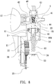
- an air compressor according to one embodiment of the present invention is shown, which generally includes a box 1 and a compressor unit (see FIG. 3 ) installed in the box 1.
- the compressor unit includes a cylinder 3, which allows a piston body 6 to operate therein, and a main frame 20 for mounting a motor 21.
- the main frame 20 also mounts a transmission mechanism, which includes a pinion 22, and a gear 23.
- the crankpin 24 attached to the gear 23 is pivotally connected with the piston body 6.
- the motor 21 can drive the transmission mechanism to have the piston body 6 conduct reciprocating motion along the inner surface 34 of the cylinder 3 to produce compressed air, which can push a plug 44 up and compress a compression spring 46 on the plug 44 to allow the compressed air to flow into an air storage container 4.
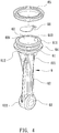
- the piston body 6 has a head 61 which defines an intake channel 604 extending therethrough, and an air receiving space 60, so that the pressure of the compressed air produced from the reciprocating motion in the cylinder 3 will not exceed the safety pressure of an object to be inflated, so that the compressor unit does not require installation of a safety valve. Therefore, a user can use the compressor unit to inflate an object more conveniently, and the object can be protected from over-inflation.
- the piston body 6 has a rod 62 in addition to the head 61.
- the head 61 of the piston body 6 defines the air receiving space 60, which extends downwardly from a top opening 601 at the top of the head 61 and is bounded by a bottom surface 602 and a surrounding surface 603.
- the intake channel 604 extends downwardly from the bottom surface 602 of the air receiving space 60.
- the bottom surface 602 of the air receiving space 60 is provided with a mounting post 605.
- the head 61 of the piston body 6 forms a flat top flange 611 at the periphery of the top opening 601 of the air receiving space 60, and forms a flat bottom flange 612 below the top flange 611.
- the head 61 of the piston body 6 defines an annular groove 64 at its outer surface, between the top flange 611 and the bottom flange 612, wherein the annular groove 64 does not communicate with the air receiving space 60.
- the bottom flange 612 of the head 61 is joined to a first end 621 of the rod 62 which has a predetermined length.
- the lower end, i.e. the second end 622, of the rod 62 defines a pivot hole 63.
- An air-tight ring 65 which functions as an O-ring, is fitted into the annular groove 64 of the head 61 of the piston body 6.
- a resilient sheet 66 is mounted on the mounting post 605 provided on the bottom surface 602 of the air receiving space 60.
- FIGS. 3 , and 6 through 8 The operation of the compressor unit of the present invention can be referred to FIGS. 3 , and 6 through 8 , wherein the cylinder 3 has a top wall 32 which serves as a top border of an inner space 31 of the cylinder 3.
- the top wall 32 defines an exit hole 33, which can communicate with the air storage container 4 on the cylinder 3.
- the air storage container 4 is provided with a plurality of outlets 41, 42, 43 (see also FIG. 10 for the outlet 43), wherein the outlet 41 can be connected with a hose 14; the outlet 42 can be connected with a pressure gauge 12; the outlet 43 can be connected with a relief valve 5, which is provided with a soft cap 51 at its inmost end.
- the plug 44 is provided in the air storage container 4, on the exit hole 33, wherein the top of the plug 44 is urged by the compression spring 46.
- the entire compressor unit is installed in the box 1, wherein the box 1 (see FIG. 1 ) is provided with a switch 11 for starting or stopping the compressor unit; the pressure gauge 12 is exposed to outside of the box 1; a button 13 has a push bar 131 inserted through a bolt 52 fitted onto the outlet 43 to touch the soft cap 51 of the relief valve 5.
- a user may depress the button 13 to press the soft cap 51 of the relief valve 5, so that the soft cap 51 can be deformed to allow excessive air to release from the outlet 43 where the relief valve 5 is installed.
- the hose 14 connected to the outlet 41 can be accommodated in the box 1, and can be closed by a lid 15 (see FIG. 2 ) to have an aesthetic appearance.
- the piston body 6 of the compressor unit can conduct reciprocating motion in the cylinder 3.
- the air contained in the inner space 31 can be forced to flow into the inner space 45 of the air storage container 4, and then can flow into an object to be inflated by way of the hose 14 connected with the outlet 41.
- the resilient sheet 66 can be pushed up, and outside air can be pulled into the inner space 31 of the cylinder 3 by way of the intake channel 604. As such, repetitive upward and downward strokes will make the object fully inflated.
- FIGS. 6 and 7 show the operational states of the piston body 6 that conduct reciprocating motion in the cylinder 3.
- FIG. 9 shows another embodiment of the compressor unit, wherein when the piston body 6 reaches top dead center, a space 31 is existed between the top of the head 61 of the piston body 6 and the top wall 32 of the cylinder 32, and this allows the piston body 3 to conduct reciprocating motion even more smoothly.
- FIGS. 11 and 12 show a second embodiment of the piston body used in the present invention, wherein the piston body 7 has a head 71 and a rod 72.
- the head 71 forms a flat top flange 711 at its top and defines an intake channel 702 extending downwardly from the top flange 711.
- a mounting post 713 is formed on the top flange 711.
- the head 71 also defines an air receiving space 70 which extends downwardly from a top opening 701 at the top flange 711 and does not communicate with the intake channel 702.
- the head 71 forms a bottom flange 712 below the top flange 712.
- the head 71 defines at its outer surface, between the top flange 711 and the bottom flange 712, an annular groove 74, which does not communicate with the air receiving space 70.
- the bottom flange 712 of the head 71 is joined to a first end 721 of the rod 72 which has a predetermined length.
- the other end, i.e. the second end 722, of the rod 72 defines a pivot hole 73.
- An air-tight ring 75 which functions as an O-ring, is fitted into the annular groove 74 of the head 71.
- a resilient sheet 76 is mounted on the mounting post 713 provided on the top flange 711 of the head 71.
- FIGS. 13 and 14 show the operational states of the piston body 7 that conducts reciprocating motion in the cylinder 3.
- the air receiving space 70 can store additional compressed air, so that the motion resistance of the piston body 7 can be reduced, and thus the piston body 7 can conduct reciprocating motion more smoothly.
- the pressure in an inflated object to be inflated will keep less than a safety pressure of the object, so that the inflating operation can be conducted more safely.
- a safety valve which is usually installed on an air compressor, can be saved.
- the head 61 of the piston body 6 defines an air receiving space 60, which can limit the air pressure of the compressed air being transferred to an object without requiring the compressor unit to install a safety valve.
Landscapes
- Engineering & Computer Science (AREA)
- Mechanical Engineering (AREA)
- General Engineering & Computer Science (AREA)
- Compressor (AREA)
- Compressors, Vaccum Pumps And Other Relevant Systems (AREA)
Priority Applications (2)
| Application Number | Priority Date | Filing Date | Title |
|---|---|---|---|
| PL13874732T PL2955383T3 (pl) | 2013-02-07 | 2013-02-07 | Budowa sprężarki powietrza |
| HUE13874732A HUE045324T2 (hu) | 2013-02-07 | 2013-02-07 | Légkompresszor konstrukció |
Applications Claiming Priority (1)
| Application Number | Priority Date | Filing Date | Title |
|---|---|---|---|
| PCT/CN2013/071531 WO2014121496A1 (zh) | 2013-02-07 | 2013-02-07 | 空气压缩机构造 |
Publications (3)
| Publication Number | Publication Date |
|---|---|
| EP2955383A1 EP2955383A1 (en) | 2015-12-16 |
| EP2955383A4 EP2955383A4 (en) | 2016-09-28 |
| EP2955383B1 true EP2955383B1 (en) | 2019-05-01 |
Family
ID=51299203
Family Applications (1)
| Application Number | Title | Priority Date | Filing Date |
|---|---|---|---|
| EP13874732.4A Active EP2955383B1 (en) | 2013-02-07 | 2013-02-07 | Air compressor construction |
Country Status (8)
| Country | Link |
|---|---|
| EP (1) | EP2955383B1 (da) |
| JP (1) | JP6169726B2 (da) |
| KR (1) | KR20150090228A (da) |
| CN (1) | CN104956085B (da) |
| DK (1) | DK2955383T3 (da) |
| HU (1) | HUE045324T2 (da) |
| PL (1) | PL2955383T3 (da) |
| WO (1) | WO2014121496A1 (da) |
Families Citing this family (3)
| Publication number | Priority date | Publication date | Assignee | Title |
|---|---|---|---|---|
| CN105114282B (zh) * | 2015-09-24 | 2018-01-09 | 张有进 | 空压机机芯 |
| TWI778585B (zh) * | 2021-04-16 | 2022-09-21 | 周文三 | 空氣壓縮機 |
| TWI778591B (zh) * | 2021-04-21 | 2022-09-21 | 周文三 | 空氣壓縮機汽缸內的多孔活塞體 |
Family Cites Families (14)
| Publication number | Priority date | Publication date | Assignee | Title |
|---|---|---|---|---|
| US302978A (en) * | 1884-08-05 | Air-compressor | ||
| JPH0219598Y2 (da) * | 1987-05-30 | 1990-05-30 | ||
| US5655887A (en) * | 1996-09-11 | 1997-08-12 | Chou; Wen-San | Valved Piston arrangement for an electric motor driven air compressor |
| US5902097A (en) * | 1997-05-19 | 1999-05-11 | Wu; Scott | Pumping device with a clamping nozzle for various valves |
| CN2369008Y (zh) * | 1999-03-22 | 2000-03-15 | 周文三 | 活塞改进的空气压缩机 |
| CN100432433C (zh) * | 2002-12-11 | 2008-11-12 | 周文三 | 空气压缩机活塞体构造 |
| JP2004190625A (ja) * | 2002-12-13 | 2004-07-08 | Bunsan Shu | 空気圧縮機用ピストン |
| CN2596067Y (zh) * | 2003-01-13 | 2003-12-31 | 华广汇工业股份有限公司 | 空压机 |
| TWI235790B (en) * | 2004-02-29 | 2005-07-11 | Wen-Shan Chou | Miniature simple air filling device |
| JP4392292B2 (ja) * | 2004-06-01 | 2009-12-24 | 住友ゴム工業株式会社 | 小型簡易コンプレッサ装置 |
| CN101240784B (zh) * | 2007-02-05 | 2010-05-19 | 周文三 | 空气压缩机的活塞体构造 |
| CN101240785A (zh) * | 2007-02-05 | 2008-08-13 | 周文三 | 空气压缩机的活塞体构造改良 |
| CN101429935B (zh) * | 2007-11-07 | 2012-03-07 | 周文三 | 空气压缩机的活塞体结构 |
| JP4369981B2 (ja) * | 2008-04-30 | 2009-11-25 | 住友ゴム工業株式会社 | コンプレッサ装置 |
-
2013
- 2013-02-07 KR KR1020157017328A patent/KR20150090228A/ko not_active Application Discontinuation
- 2013-02-07 EP EP13874732.4A patent/EP2955383B1/en active Active
- 2013-02-07 JP JP2015555531A patent/JP6169726B2/ja active Active
- 2013-02-07 DK DK13874732.4T patent/DK2955383T3/da active
- 2013-02-07 PL PL13874732T patent/PL2955383T3/pl unknown
- 2013-02-07 CN CN201380069836.0A patent/CN104956085B/zh active Active
- 2013-02-07 HU HUE13874732A patent/HUE045324T2/hu unknown
- 2013-02-07 WO PCT/CN2013/071531 patent/WO2014121496A1/zh active Application Filing
Non-Patent Citations (1)
| Title |
|---|
| None * |
Also Published As
| Publication number | Publication date |
|---|---|
| WO2014121496A1 (zh) | 2014-08-14 |
| HUE045324T2 (hu) | 2019-12-30 |
| KR20150090228A (ko) | 2015-08-05 |
| DK2955383T3 (da) | 2019-08-05 |
| EP2955383A4 (en) | 2016-09-28 |
| JP2016505114A (ja) | 2016-02-18 |
| EP2955383A1 (en) | 2015-12-16 |
| PL2955383T3 (pl) | 2019-10-31 |
| CN104956085A (zh) | 2015-09-30 |
| CN104956085B (zh) | 2017-09-05 |
| JP6169726B2 (ja) | 2017-07-26 |
Similar Documents
| Publication | Publication Date | Title |
|---|---|---|
| EP2930361B1 (en) | Air compressor | |
| EP2960502B1 (en) | Portable air compressor | |
| EP2930362B1 (en) | Air compressor | |
| EP2937568B1 (en) | Air compressor | |
| EP2955383B1 (en) | Air compressor construction | |
| EP2955381B1 (en) | Air compressor apparatus | |
| EP2955382B1 (en) | Piston body construction of air compressor | |
| TWI548812B (zh) | 空氣壓縮機裝置 | |
| JP2018021515A (ja) | コンプレッサー装置 | |
| US20140286804A1 (en) | Air compressor having buffering compartment | |
| EP2955380B1 (en) | Air compressor apparatus | |
| US20140023537A1 (en) | Air Pump Cylinder | |
| JP6302257B2 (ja) | コンプレッサー装置 | |
| US9328725B2 (en) | Air compressor having buffering compartment | |
| TWI598511B (zh) | 空氣壓縮機裝置 | |
| TWI568934B (zh) | 空氣壓縮機的活塞體構造 | |
| TWI526619B (zh) | 空氣壓縮機裝置 |
Legal Events
| Date | Code | Title | Description |
|---|---|---|---|
| PUAI | Public reference made under article 153(3) epc to a published international application that has entered the european phase |
Free format text: ORIGINAL CODE: 0009012 |
|
| 17P | Request for examination filed |
Effective date: 20150812 |
|
| AK | Designated contracting states |
Kind code of ref document: A1 Designated state(s): AL AT BE BG CH CY CZ DE DK EE ES FI FR GB GR HR HU IE IS IT LI LT LU LV MC MK MT NL NO PL PT RO RS SE SI SK SM TR |
|
| AX | Request for extension of the european patent |
Extension state: BA ME |
|
| DAX | Request for extension of the european patent (deleted) | ||
| A4 | Supplementary search report drawn up and despatched |
Effective date: 20160826 |
|
| RIC1 | Information provided on ipc code assigned before grant |
Ipc: F04B 39/12 20060101ALI20160822BHEP Ipc: F04B 35/06 20060101ALI20160822BHEP Ipc: F04B 39/00 20060101ALI20160822BHEP Ipc: F04B 35/04 20060101ALI20160822BHEP Ipc: F04B 53/14 20060101AFI20160822BHEP Ipc: F04B 33/00 20060101ALI20160822BHEP Ipc: F04B 41/02 20060101ALI20160822BHEP |
|
| STAA | Information on the status of an ep patent application or granted ep patent |
Free format text: STATUS: EXAMINATION IS IN PROGRESS |
|
| 17Q | First examination report despatched |
Effective date: 20180219 |
|
| GRAP | Despatch of communication of intention to grant a patent |
Free format text: ORIGINAL CODE: EPIDOSNIGR1 |
|
| STAA | Information on the status of an ep patent application or granted ep patent |
Free format text: STATUS: GRANT OF PATENT IS INTENDED |
|
| INTG | Intention to grant announced |
Effective date: 20181106 |
|
| GRAS | Grant fee paid |
Free format text: ORIGINAL CODE: EPIDOSNIGR3 |
|
| GRAA | (expected) grant |
Free format text: ORIGINAL CODE: 0009210 |
|
| STAA | Information on the status of an ep patent application or granted ep patent |
Free format text: STATUS: THE PATENT HAS BEEN GRANTED |
|
| AK | Designated contracting states |
Kind code of ref document: B1 Designated state(s): AL AT BE BG CH CY CZ DE DK EE ES FI FR GB GR HR HU IE IS IT LI LT LU LV MC MK MT NL NO PL PT RO RS SE SI SK SM TR |
|
| REG | Reference to a national code |
Ref country code: GB Ref legal event code: FG4D |
|
| REG | Reference to a national code |
Ref country code: CH Ref legal event code: EP Ref country code: AT Ref legal event code: REF Ref document number: 1127291 Country of ref document: AT Kind code of ref document: T Effective date: 20190515 |
|
| REG | Reference to a national code |
Ref country code: DE Ref legal event code: R096 Ref document number: 602013054829 Country of ref document: DE |
|
| REG | Reference to a national code |
Ref country code: IE Ref legal event code: FG4D |
|
| REG | Reference to a national code |
Ref country code: NL Ref legal event code: FP |
|
| REG | Reference to a national code |
Ref country code: DK Ref legal event code: T3 Effective date: 20190731 |
|
| REG | Reference to a national code |
Ref country code: SE Ref legal event code: TRGR |
|
| REG | Reference to a national code |
Ref country code: LT Ref legal event code: MG4D |
|
| PG25 | Lapsed in a contracting state [announced via postgrant information from national office to epo] |
Ref country code: ES Free format text: LAPSE BECAUSE OF FAILURE TO SUBMIT A TRANSLATION OF THE DESCRIPTION OR TO PAY THE FEE WITHIN THE PRESCRIBED TIME-LIMIT Effective date: 20190501 Ref country code: LT Free format text: LAPSE BECAUSE OF FAILURE TO SUBMIT A TRANSLATION OF THE DESCRIPTION OR TO PAY THE FEE WITHIN THE PRESCRIBED TIME-LIMIT Effective date: 20190501 Ref country code: HR Free format text: LAPSE BECAUSE OF FAILURE TO SUBMIT A TRANSLATION OF THE DESCRIPTION OR TO PAY THE FEE WITHIN THE PRESCRIBED TIME-LIMIT Effective date: 20190501 Ref country code: PT Free format text: LAPSE BECAUSE OF FAILURE TO SUBMIT A TRANSLATION OF THE DESCRIPTION OR TO PAY THE FEE WITHIN THE PRESCRIBED TIME-LIMIT Effective date: 20190901 Ref country code: NO Free format text: LAPSE BECAUSE OF FAILURE TO SUBMIT A TRANSLATION OF THE DESCRIPTION OR TO PAY THE FEE WITHIN THE PRESCRIBED TIME-LIMIT Effective date: 20190801 Ref country code: AL Free format text: LAPSE BECAUSE OF FAILURE TO SUBMIT A TRANSLATION OF THE DESCRIPTION OR TO PAY THE FEE WITHIN THE PRESCRIBED TIME-LIMIT Effective date: 20190501 Ref country code: FI Free format text: LAPSE BECAUSE OF FAILURE TO SUBMIT A TRANSLATION OF THE DESCRIPTION OR TO PAY THE FEE WITHIN THE PRESCRIBED TIME-LIMIT Effective date: 20190501 |
|
| PG25 | Lapsed in a contracting state [announced via postgrant information from national office to epo] |
Ref country code: RS Free format text: LAPSE BECAUSE OF FAILURE TO SUBMIT A TRANSLATION OF THE DESCRIPTION OR TO PAY THE FEE WITHIN THE PRESCRIBED TIME-LIMIT Effective date: 20190501 Ref country code: LV Free format text: LAPSE BECAUSE OF FAILURE TO SUBMIT A TRANSLATION OF THE DESCRIPTION OR TO PAY THE FEE WITHIN THE PRESCRIBED TIME-LIMIT Effective date: 20190501 Ref country code: BG Free format text: LAPSE BECAUSE OF FAILURE TO SUBMIT A TRANSLATION OF THE DESCRIPTION OR TO PAY THE FEE WITHIN THE PRESCRIBED TIME-LIMIT Effective date: 20190801 Ref country code: GR Free format text: LAPSE BECAUSE OF FAILURE TO SUBMIT A TRANSLATION OF THE DESCRIPTION OR TO PAY THE FEE WITHIN THE PRESCRIBED TIME-LIMIT Effective date: 20190802 |
|
| REG | Reference to a national code |
Ref country code: HU Ref legal event code: AG4A Ref document number: E045324 Country of ref document: HU |
|
| PG25 | Lapsed in a contracting state [announced via postgrant information from national office to epo] |
Ref country code: IS Free format text: LAPSE BECAUSE OF FAILURE TO SUBMIT A TRANSLATION OF THE DESCRIPTION OR TO PAY THE FEE WITHIN THE PRESCRIBED TIME-LIMIT Effective date: 20190901 |
|
| PG25 | Lapsed in a contracting state [announced via postgrant information from national office to epo] |
Ref country code: RO Free format text: LAPSE BECAUSE OF FAILURE TO SUBMIT A TRANSLATION OF THE DESCRIPTION OR TO PAY THE FEE WITHIN THE PRESCRIBED TIME-LIMIT Effective date: 20190501 Ref country code: SK Free format text: LAPSE BECAUSE OF FAILURE TO SUBMIT A TRANSLATION OF THE DESCRIPTION OR TO PAY THE FEE WITHIN THE PRESCRIBED TIME-LIMIT Effective date: 20190501 Ref country code: EE Free format text: LAPSE BECAUSE OF FAILURE TO SUBMIT A TRANSLATION OF THE DESCRIPTION OR TO PAY THE FEE WITHIN THE PRESCRIBED TIME-LIMIT Effective date: 20190501 |
|
| REG | Reference to a national code |
Ref country code: DE Ref legal event code: R097 Ref document number: 602013054829 Country of ref document: DE |
|
| PG25 | Lapsed in a contracting state [announced via postgrant information from national office to epo] |
Ref country code: SM Free format text: LAPSE BECAUSE OF FAILURE TO SUBMIT A TRANSLATION OF THE DESCRIPTION OR TO PAY THE FEE WITHIN THE PRESCRIBED TIME-LIMIT Effective date: 20190501 |
|
| PLBE | No opposition filed within time limit |
Free format text: ORIGINAL CODE: 0009261 |
|
| STAA | Information on the status of an ep patent application or granted ep patent |
Free format text: STATUS: NO OPPOSITION FILED WITHIN TIME LIMIT |
|
| 26N | No opposition filed |
Effective date: 20200204 |
|
| PG25 | Lapsed in a contracting state [announced via postgrant information from national office to epo] |
Ref country code: SI Free format text: LAPSE BECAUSE OF FAILURE TO SUBMIT A TRANSLATION OF THE DESCRIPTION OR TO PAY THE FEE WITHIN THE PRESCRIBED TIME-LIMIT Effective date: 20190501 |
|
| REG | Reference to a national code |
Ref country code: CH Ref legal event code: PL |
|
| PG25 | Lapsed in a contracting state [announced via postgrant information from national office to epo] |
Ref country code: LU Free format text: LAPSE BECAUSE OF NON-PAYMENT OF DUE FEES Effective date: 20200207 Ref country code: MC Free format text: LAPSE BECAUSE OF FAILURE TO SUBMIT A TRANSLATION OF THE DESCRIPTION OR TO PAY THE FEE WITHIN THE PRESCRIBED TIME-LIMIT Effective date: 20190501 |
|
| PG25 | Lapsed in a contracting state [announced via postgrant information from national office to epo] |
Ref country code: LI Free format text: LAPSE BECAUSE OF NON-PAYMENT OF DUE FEES Effective date: 20200229 Ref country code: CH Free format text: LAPSE BECAUSE OF NON-PAYMENT OF DUE FEES Effective date: 20200229 |
|
| PG25 | Lapsed in a contracting state [announced via postgrant information from national office to epo] |
Ref country code: IE Free format text: LAPSE BECAUSE OF NON-PAYMENT OF DUE FEES Effective date: 20200207 |
|
| PGFP | Annual fee paid to national office [announced via postgrant information from national office to epo] |
Ref country code: HU Payment date: 20220130 Year of fee payment: 10 Ref country code: GB Payment date: 20220221 Year of fee payment: 10 Ref country code: DK Payment date: 20220221 Year of fee payment: 10 Ref country code: AT Payment date: 20220215 Year of fee payment: 10 |
|
| PG25 | Lapsed in a contracting state [announced via postgrant information from national office to epo] |
Ref country code: MT Free format text: LAPSE BECAUSE OF FAILURE TO SUBMIT A TRANSLATION OF THE DESCRIPTION OR TO PAY THE FEE WITHIN THE PRESCRIBED TIME-LIMIT Effective date: 20190501 Ref country code: CY Free format text: LAPSE BECAUSE OF FAILURE TO SUBMIT A TRANSLATION OF THE DESCRIPTION OR TO PAY THE FEE WITHIN THE PRESCRIBED TIME-LIMIT Effective date: 20190501 |
|
| PGFP | Annual fee paid to national office [announced via postgrant information from national office to epo] |
Ref country code: PL Payment date: 20220110 Year of fee payment: 10 Ref country code: NL Payment date: 20220216 Year of fee payment: 10 Ref country code: IT Payment date: 20220228 Year of fee payment: 10 Ref country code: FR Payment date: 20220221 Year of fee payment: 10 Ref country code: CZ Payment date: 20220131 Year of fee payment: 10 Ref country code: BE Payment date: 20220216 Year of fee payment: 10 Ref country code: TR Payment date: 20220127 Year of fee payment: 10 Ref country code: SE Payment date: 20220221 Year of fee payment: 10 |
|
| PG25 | Lapsed in a contracting state [announced via postgrant information from national office to epo] |
Ref country code: MK Free format text: LAPSE BECAUSE OF FAILURE TO SUBMIT A TRANSLATION OF THE DESCRIPTION OR TO PAY THE FEE WITHIN THE PRESCRIBED TIME-LIMIT Effective date: 20190501 |
|
| REG | Reference to a national code |
Ref country code: AT Ref legal event code: UEP Ref document number: 1127291 Country of ref document: AT Kind code of ref document: T Effective date: 20190501 |
|
| REG | Reference to a national code |
Ref country code: DK Ref legal event code: EBP Effective date: 20230228 |
|
| REG | Reference to a national code |
Ref country code: SE Ref legal event code: EUG |
|
| REG | Reference to a national code |
Ref country code: NL Ref legal event code: MM Effective date: 20230301 |
|
| REG | Reference to a national code |
Ref country code: AT Ref legal event code: MM01 Ref document number: 1127291 Country of ref document: AT Kind code of ref document: T Effective date: 20230207 |
|
| REG | Reference to a national code |
Ref country code: BE Ref legal event code: MM Effective date: 20230228 |
|
| GBPC | Gb: european patent ceased through non-payment of renewal fee |
Effective date: 20230207 |
|
| PG25 | Lapsed in a contracting state [announced via postgrant information from national office to epo] |
Ref country code: SE Free format text: LAPSE BECAUSE OF NON-PAYMENT OF DUE FEES Effective date: 20230208 Ref country code: CZ Free format text: LAPSE BECAUSE OF NON-PAYMENT OF DUE FEES Effective date: 20230207 Ref country code: AT Free format text: LAPSE BECAUSE OF NON-PAYMENT OF DUE FEES Effective date: 20230207 |
|
| PG25 | Lapsed in a contracting state [announced via postgrant information from national office to epo] |
Ref country code: NL Free format text: LAPSE BECAUSE OF NON-PAYMENT OF DUE FEES Effective date: 20230301 Ref country code: HU Free format text: LAPSE BECAUSE OF NON-PAYMENT OF DUE FEES Effective date: 20230208 |
|
| PG25 | Lapsed in a contracting state [announced via postgrant information from national office to epo] |
Ref country code: GB Free format text: LAPSE BECAUSE OF NON-PAYMENT OF DUE FEES Effective date: 20230207 |
|
| PG25 | Lapsed in a contracting state [announced via postgrant information from national office to epo] |
Ref country code: IT Free format text: LAPSE BECAUSE OF NON-PAYMENT OF DUE FEES Effective date: 20230207 Ref country code: GB Free format text: LAPSE BECAUSE OF NON-PAYMENT OF DUE FEES Effective date: 20230207 Ref country code: FR Free format text: LAPSE BECAUSE OF NON-PAYMENT OF DUE FEES Effective date: 20230228 Ref country code: DK Free format text: LAPSE BECAUSE OF NON-PAYMENT OF DUE FEES Effective date: 20230228 |
|
| PG25 | Lapsed in a contracting state [announced via postgrant information from national office to epo] |
Ref country code: BE Free format text: LAPSE BECAUSE OF NON-PAYMENT OF DUE FEES Effective date: 20230228 |
|
| PGFP | Annual fee paid to national office [announced via postgrant information from national office to epo] |
Ref country code: DE Payment date: 20240226 Year of fee payment: 12 |