EP2954986A1 - Apparatus and method for managing and controlling motion of a multiple body system - Google Patents
Apparatus and method for managing and controlling motion of a multiple body system Download PDFInfo
- Publication number
- EP2954986A1 EP2954986A1 EP14171752.0A EP14171752A EP2954986A1 EP 2954986 A1 EP2954986 A1 EP 2954986A1 EP 14171752 A EP14171752 A EP 14171752A EP 2954986 A1 EP2954986 A1 EP 2954986A1
- Authority
- EP
- European Patent Office
- Prior art keywords
- tcp
- movement
- force
- regulating
- controlling
- Prior art date
- Legal status (The legal status is an assumption and is not a legal conclusion. Google has not performed a legal analysis and makes no representation as to the accuracy of the status listed.)
- Granted
Links
Images


Classifications
-
- G—PHYSICS
- G05—CONTROLLING; REGULATING
- G05D—SYSTEMS FOR CONTROLLING OR REGULATING NON-ELECTRIC VARIABLES
- G05D17/00—Control of torque; Control of mechanical power
- G05D17/02—Control of torque; Control of mechanical power characterised by the use of electric means
-
- B—PERFORMING OPERATIONS; TRANSPORTING
- B25—HAND TOOLS; PORTABLE POWER-DRIVEN TOOLS; MANIPULATORS
- B25J—MANIPULATORS; CHAMBERS PROVIDED WITH MANIPULATION DEVICES
- B25J9/00—Programme-controlled manipulators
- B25J9/16—Programme controls
- B25J9/1628—Programme controls characterised by the control loop
- B25J9/1638—Programme controls characterised by the control loop compensation for arm bending/inertia, pay load weight/inertia
-
- G—PHYSICS
- G05—CONTROLLING; REGULATING
- G05B—CONTROL OR REGULATING SYSTEMS IN GENERAL; FUNCTIONAL ELEMENTS OF SUCH SYSTEMS; MONITORING OR TESTING ARRANGEMENTS FOR SUCH SYSTEMS OR ELEMENTS
- G05B13/00—Adaptive control systems, i.e. systems automatically adjusting themselves to have a performance which is optimum according to some preassigned criterion
- G05B13/02—Adaptive control systems, i.e. systems automatically adjusting themselves to have a performance which is optimum according to some preassigned criterion electric
- G05B13/04—Adaptive control systems, i.e. systems automatically adjusting themselves to have a performance which is optimum according to some preassigned criterion electric involving the use of models or simulators
-
- G—PHYSICS
- G05—CONTROLLING; REGULATING
- G05B—CONTROL OR REGULATING SYSTEMS IN GENERAL; FUNCTIONAL ELEMENTS OF SUCH SYSTEMS; MONITORING OR TESTING ARRANGEMENTS FOR SUCH SYSTEMS OR ELEMENTS
- G05B2219/00—Program-control systems
- G05B2219/30—Nc systems
- G05B2219/39—Robotics, robotics to robotics hand
- G05B2219/39176—Compensation deflection arm
-
- G—PHYSICS
- G05—CONTROLLING; REGULATING
- G05B—CONTROL OR REGULATING SYSTEMS IN GENERAL; FUNCTIONAL ELEMENTS OF SUCH SYSTEMS; MONITORING OR TESTING ARRANGEMENTS FOR SUCH SYSTEMS OR ELEMENTS
- G05B2219/00—Program-control systems
- G05B2219/30—Nc systems
- G05B2219/39—Robotics, robotics to robotics hand
- G05B2219/39194—Compensation gravity
-
- G—PHYSICS
- G05—CONTROLLING; REGULATING
- G05B—CONTROL OR REGULATING SYSTEMS IN GENERAL; FUNCTIONAL ELEMENTS OF SUCH SYSTEMS; MONITORING OR TESTING ARRANGEMENTS FOR SUCH SYSTEMS OR ELEMENTS
- G05B2219/00—Program-control systems
- G05B2219/30—Nc systems
- G05B2219/39—Robotics, robotics to robotics hand
- G05B2219/39319—Force control, force as reference, active compliance
Definitions
- the present invention relates to a device for controlling and regulating a movement of a system with a plurality of kinematically interacting individual bodies, of which at least one is a drive. Moreover, the present invention relates to a method for controlling and controlling a movement of such a system. Under such a system is understood, for example, a plant, a processing machine, a processing machine and in particular a robot or a machine tool.
- the drive is, for example, an electric motor or a hydraulic or pneumatic drive.
- Another approach to improve the absolute static accuracy is based on a reference position to measure the deviation at the TCP in a variety of points of the working space and add as a compensation value to the setpoint channel or to subtract from the actual value channel.
- the disadvantage of this method is the necessary effort and the cost of measuring the working space or the robot / machine. Measuring the deviations requires equipping the system with external measuring equipment. The grid of the measurement is determined on a case-by-case basis. The analysis must be repeated in each identical system.
- the tabulated correction values are also load-dependent, i. they apply exactly to a load case. Changes z. As the load, the values are no longer valid.
- the counterforce is based on a not infinitely rigid structure and can quite cause parasitic movements on the TCP.
- a robot arm has a plurality of links which are each movable with a motor (a link with associated drive or motor represents a motion axis, "axis" for short)
- the motion, in particular an acceleration, of one link can be applied to the link affect others, reducing the quasi-static accuracy being affected.
- the parasitic movement resulting from an acceleration of the leading axis has hitherto been compensated with a compensation value applied as a position setpoint.
- the torque is often controlled by a so-called torque precontrol.
- the parameterization of the torque precontrol requires the input of the axis moment of inertia in relation to the motor. On industrial robots, however, this information is not constant over the working space due to the structure.
- the total inertia seen by the engine is a function of the joint position. To calculate a torque setpoint so far, the engine acceleration is multiplied by a predetermined value of the axial inertia.
- the parameterization of the maximum axis acceleration takes place as a consequence of the design of the motor and the power section and is derived axis-wise from the maximum permissible current and the axis inertia. Since the maximum acceleration is to be entered as a constant value, only the point is relevant for its parameterization, where the axis inertia related to the motor reaches its maximum. It follows that in areas where this value is not reached, the power reserve is not utilized and a higher acceleration limit would theoretically be possible. Therefore, it may be desirable to calculate an acceleration reserve for each position or an adjustment of the acceleration limit for better utilization of the current limit. In path planning, position-dependent acceleration limits have not been considered so far.
- the object of the present invention is thus to propose a device for controlling and a corresponding method for controlling and regulating a movement of a system with a plurality of kinematically interacting individual bodies, in which the movement of the system as such can be carried out more accurately.
- the force-generating variable is the electric current, while the force-generating variable is the pressure in a hydraulic or pneumatic drive.
- the movement of the system is continuously controlled dynamically.
- force vectors and corresponding compensating variables are constantly recalculated so that a given trajectory can be better maintained.
- Precise trajectory compliance is required in many manufacturing tasks, but not in most pick-and-place tasks where known solutions are required EP 1 980 374 A2 suffice.
- the compensation quantity may be a compensation torque, a compensation force, a compensation speed or a compensation position.
- each of these sizes can be used individually or in combination to compensate.
- a control with the compensation torque as compensating variable leads to a more rapid compensation of the disturbing forces.
- a control with the compensation position as a compensation variable leads to a more precise compensation of the disturbing forces.
- the load calculating device preferably draws on a load model in which a location and / or direction and / or amplitude of a force introduction into one of the individual bodies is / are taken into account. In this way, the force introduction with all its parameters can be considered dynamically during a movement.
- control unit has a cascaded position control, speed control and current control (or regulation of the force-generating variable). This allows the movement of the system to be precisely controlled in all its details.
- the moment-calculating device for calculating the at least one balancing torque uses a multi-body model in which a mass and / or an elasticity and / or a damping and / or a linear dependence on degrees of freedom of each of the individual bodies is / are taken into account. In this way, all or the most important mechanical quantities can be taken into account when modeling the system.
- the multi-body model may be based on a linear differential equation system. This has the advantage that it can be solved without high computational effort.
- the differential equation system is based on a mass matrix, a damping matrix and a stiffness matrix in each case based on the individual bodies.
- the major mechanical parameters such as mass, damping and stiffness enter the multi-body model.
- inertial forces possibly also the Coriolis force
- centrifugal forces which respectively act on the individual bodies
- a maximum acceleration of one of the individual bodies or of a composite of a plurality of the individual bodies can be calculated continuously during the movement. This has the advantage that in each position, the acceleration limit can be adapted to better use of the current limit or pressure limit.
- the torque device and the control unit are designed so that they continuously reduce the excitation of at least one natural frequency of the system during the movement. This means that the natural frequencies are less excited, which leads to a better movement behavior of the system.
- the device for controlling and regulating may have a model of the controlled system of the system, wherein at least one ideal reference variable for the drive can be calculated with the model. This allows a definable dynamic for the axes to be specified.
- control and regulating device may comprise a model of the controlled system of the system, the model having an ideal torque of the drive for monitoring an actual torque of the drive is calculable.
- a model of the controlled system for example, drive torques of the real system can be monitored, as a result of which collisions can be deduced.
- a device may be used to control and regulate the movement of its multiple, kinematically interacting, single bodies.
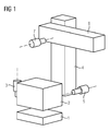
- FIG. 1 An example of such a multi-body system is in FIG. 1 played.
- This robot stands, for example, on a base plate 1.
- a robot body 2 can rotate on a vertical axis above the base plate 1. The rotation takes place by means of a motor 3.
- a motor 3 Although the following examples refer to an electric motor as a drive, in each case also a different drive can be used. In hydraulic and pneumatic drives then the pressure is the decisive factor instead of the current.
- the robot body 2 together with the motor 3 is a movement axis (in short: axis).
- a first arm 4 is rotatably supported by means of a motor 5.
- a second arm 6 is also rotatably supported by means of a further motor 7.
- the robot thus has three axes, of which the first axis with the individual bodies 2 (possibly including the motor 3), the second axis with the individual bodies 4 (possibly including motor 5) and the third axis with the individual bodies 6 (if necessary. including motor 7) is formed.
- each axis or each individual body has its own individual mass, damping, stiffness, etc. This means that, for example, the force of gravity or a process force has different effects on the system, depending on the position in which the axes are to each other. For example, if at the top of in FIG. 1 horizontally drawn second arm 6 pulls a force down, this has on the absolute position of the tip of the second arm 6 has a different effect than in the case that the second arm 6, for example, directed vertically upwards. Every force on the system has thus depending on the position of all axes effect.
- the behavior of the system can be described in a multi-body model representing a three-dimensional mechanical MIMO (multiple input, multiple output) model.
- M is the mass matrix
- D is the attenuation matrix
- K is the stiffness matrix
- T is the rectangular transformation matrix, which represents the relationship between the state quantities X and all degrees of freedom of the model.
- Each individual body of the system (see reference numerals 1, 2, 4 and 6 of FIG 1 ) is inherently rigid and has exactly six degrees of freedom (three translations and three rotations).
- the vector f is the vector of the external forces at the center of gravity of the respective individual body.
- this force vector includes gravity for each individual body and optionally a process force and the like (eg a force caused by pressing a tool against a workpiece).
- the state vector X describes the small movements around the original operating point.
- the matrices M, D, K and T are independent of the state variables.
- the joint position is not a state variable, but further parameters for the calculation of the matrices M, D, K and T.
- the model is preferably a linear multibody system that takes into account the positional dependence of the system behavior.
- An improved absolute accuracy can namely be achieved in that at any time engine forces to compensate for all disturbing forces are initiated. This results in an equilibrium state in which the small deviations at the TCP are zero.
- the description of the load case contains information about the location (s), the direction (s) and the amplitude (s) of the force application.
- As a force in addition to the aforementioned disturbing forces and machining forces are introduced, as they arise, for example, when milling or drilling.
- the matrix T TCP is an excerpt from the matrix T and describes the linear dependence between the coordinates of the TCP and the state variables.
- An important prerequisite for the solvability of the problem is that all zeros declared TCP coordinates are movable by the motors. However, this is the case for all machine and robot kinematics considered here. The robot must therefore be able to move the respective tool in the desired direction.
- the transmission of the engine torque to the mechanical structure requires the tensioning of the drive train spring by an angular offset on the engine.
- This angular offset is derived from the state vector X and must be taken into account in the setpoint generation.
- FIG. 2 shows the structure of a method and a corresponding device for controlling and regulating the compensation of disturbance forces.
- Target coordinates for the TCP are specified by a higher-level unit, namely X TCP , Y TCP and Z TCP and ⁇ TCP , ⁇ TCP , ⁇ TCP .
- a coordinate transformation KF
- KF coordinate transformation
- a force vector f is determined for the respective joint coordinates as a function of a position, a direction and an amplitude of the force introduction. This is preferably done for each single body of the system.
- a multi-body model 10 processes the force vectors or the Force vector f further. On its basis and the basis of the joint coordinates, an engine torque or a corresponding current equivalent is calculated for the respective motor of each axle. In addition, in the multi-body model 10, angle offsets ⁇ are also calculated here. These calculations take into account the mass properties, the elasticity, the damping and linear dependencies of the degrees of freedom of the respective axes or individual bodies.
- the multi-body model 10 is based on the second-order linear differential equation system presented above.
- a control unit 11 connected downstream of the multi-body model 10 determines from the joint coordinates ⁇ 1 , ⁇ 2 , ⁇ 3 ,..., ⁇ i ,..., ⁇ n , the angular offsets ⁇ and the engine torques M a current i for driving an in FIG. 2 not shown engine one of the axes of the system, whereby the parasitic motion due to the disturbing forces is reduced or compensated.
- the control unit preferably has a cascaded position control, speed control and current control.
- a position controller 12 (preferably a P controller) is provided, which receives as an input quantity a sign-correct sum of the joint coordinates ⁇ 1 to ⁇ n , the angular offsets ⁇ and actual coordinates ⁇ j .
- the manipulated variable of the position controller 12 serves as an input variable for a downstream speed control, this input variable is summed an actual angular velocity ⁇ j in an adder 14 with the correct sign.
- the sum signal is fed to a speed controller 15 (preferably a PI controller).
- the output signal of the speed control or the speed controller 15 serves as input for a current control.
- This input variable is added in an adder a respective motor torque M and a corresponding equivalent and an actual current I j with the correct sign in an adder 16.
- This adder 16 as well as the other two adders 13 and 14 (in general: logic elements) optionally have a conversion or amplification functionality to obtain the respective desired size, for example by multiplication.
- the output signal of the adder 16 is fed to a current regulator 17, which outputs the manipulated variable for the motor, namely the current i.
- FIG. 2 For the sake of clarity, is in FIG. 2 a Störkraftkompensation only for a single axis shown. However, appropriate calculations and controls are preferably made for all axes of the system. In the simplest case, individual current values are calculated for each axis with which the respective motors are controlled.
- the multi-body model 10 can therefore be used to compensate for static disturbance forces from known load cases due to engine forces during the entire movement, ie always for the current coordinates and the current actual values.
- the multi-body model can be used to compensate for quasi-static load cases as well as acceleration operations.
- the acceleration of an axis and the counterforce generated in the joint may possibly lead to parasitic movements on the TCP due to the resilience of the structure.
- the second axle changes position or tilt due to its finite rigidity.
- Such and similar parasitic movements can be compensated for by means of compensatory movements of the remaining axes.
- the calculated compensation movement is pre-controlled as speed and torque.
- Such precontrol is for n axes A1, A2,..., Ai,..., An in FIG. 3 played.
- the regulatory structure is based on that of FIG. 2 , Identical elements are provided with the same reference numerals. In the following, only the differences are highlighted.
- control unit 11 receives as inputs the joint coordinate ⁇ 1 of the transformation unit 8 and the angular offset ⁇ 1 , a speed offset ⁇ 1 and a balancing moment M 1 of the multi-body model 10.
- control unit 11 i receives the joint coordinate ⁇ i from the transformation unit 8 and the angular offset ⁇ 2 , a speed offset ⁇ i and a compensation torque M i from the multi-body model 10.
- All n control units 11 1 to 11 n are structurally the same. Therefore, only the first control unit 11 1 will be described in detail here. It is based on the control unit 11 of FIG. 2 , whose description is referred again here. This results in accordance with the position controller 12 1 , the speed controller 15 1 and the current regulator 17 1 and the adder 13 1 , 14 1 and 16 first In the control unit 11 1, a first differentiator 18 1 is here additionally provided an additional guide value is determined taking into consideration the speed offset ⁇ 1 for the speed control with that of the angular displacement ⁇ 1, this reference variable is taken into account in the adder 14.
- this further speed control variable is converted into an acceleration variable and then multiplied in a multiplier 20 1 with a total axis inertia J Mot1 .
- the resulting value is finally made available to the adder 16 1 taking into account the compensation torque M 1 .
- the current signal i 1 results in driving the first axis.
- the current signals i i in the control unit 11 i are generated. In this way, parasitic movements that arise due to a quasi-static force can be compensated by appropriate compensatory movements.
- the axis inertia related to the respective engine can be calculated become.
- the axis inertia is determined from the modal mass associated with the rigid body mode (natural frequency 0 Hz).
- This rigid body fashion is purely theoretical in nature and refers to a movement without any vibration.
- only one motor must be allowed to move freely.
- the remaining axes are clamped.
- To calculate the modal mass it is sufficient to know only the eigenvector associated with the rigid body mode.
- the pseudo-inversion of the eigenvector is trivial and less stressful for the computational process than the inversion of a complete matrix.
- the determination of the eigenvector associated with the rigid body mode can be carried out in a simple manner, without consideration of the residual eigenvalues and vectors.
- the methodology is explained using the example of an arbitrary quadratic matrix A.
- X i ⁇ For the calculation of the modal masses the pseudo-inverse vector X i ⁇ is needed.
- the vector can be constructed element by element.
- X i ⁇ ⁇ 1 n 0 x i ⁇ 1 x i ⁇ 2 ⁇ x ij ⁇ x in ⁇ in which ⁇ j .
- ⁇ x ij 1 x j ⁇
- For x j ⁇ 0 x ij 0 otherwise
- n 0 is the number of elements of the vector X ⁇ nonzero.
- M and K correspond to the mass and stiffness matrices of the free engine system.
- Tj is the transformation matrix that satisfies the constraints, thus clamping all the motors or axes except the jth.
- the reduced vector X red contains only the state variables of those degrees of freedom that the structure has due to the joints, while the state vector X has all degrees of freedom. Since the rigid body mode no modal damping is assigned, the damping matrix can be taken out of the system of equations.
- FIG. 4 shows a schematic representation of the structure of the torque control.
- the coefficient J Mot is the total axle inertia related to the affected axle on the engine. It is in the control unit 11, structurally the control unit 11 1 of FIG. 3 taken into account in the multiplier 20, which forms the additional reference variable for the adder 16.
- the other elements of the control unit 11 correspond to those of the control unit 11 1 of FIG. 3 and are in FIG. 4 only shown without index "1".
- the overview is further in FIG. 4 dispensed with the representation of the load model 9, although it is naturally present. The same applies to the following Figures 5 and 6 ,
- the multi-body model can therefore be used to calculate the axis inertia J Mot for parameterization of the torque precontrol for each position. Therefore, the multi-body model has 10 in FIG. 4 a special output which provides a signal to the multiplier 20 to adjust the axis inertias J mot .
- the above multi-body model which is preferably based on the said linear differential equation system, can, as stated above, for the calculation of the respective Motors related axis inertia can be used for each position. From this, maximum axis accelerations can then be determined in an optionally extended model. The current maximum axis acceleration during the movement of the system definitely has an influence on the course of the movement.
- FIG. 5 which shows a structural overview of a pilot control with setpoint filter, is again limited to one axis for the sake of clarity. As well as in FIG. 4 was also dispensed with the representation of the load model 9. The rest in FIG. 5 Components represented by the same reference numerals as in the preceding figures have the same functionality as there. It is therefore referred to the respective description there.
- a setpoint filter 21 is provided here (SWF). This receives as input signal not only position information about the joint coordinates ⁇ 1 to ⁇ n directly, but also a speed signal formed therefrom by means of a differentiator 22 and acceleration signal formed therefrom by means of a dual differentiator 23. From these three signals, the setpoint filter 21 forms a filtered acceleration signal, which is supplied to the combining unit 20, which in turn with the filtered acceleration signal the total axial inertia J Mot provided by the multi-body model 10 and a corresponding result to the adder 16 for current control as a reference variable. In addition to this precontrol of the current for the current control, the speed control is pre-controlled with a filtered speed signal, which wins the setpoint filter 21 from the simply differentiated joint coordinates. For this purpose, the filtered speed signal is input to the adder 14.
- a filtered position signal which receives the setpoint filter 21 from the joint coordinates ⁇ 1 to ⁇ n .
- This filtered position signal is supplied to the adder 13 as a reference variable.
- the setpoint filter 21 special natural frequencies of the system can then position dependent, i. each time currently during acceleration, be filtered out.
- the natural frequencies of a robot change when it changes its arm position. In the extended state of the arm namely the natural oscillations are slower than in the tightened state of the arm.
- frequencies at 15 Hz are filtered out when the robot has extended the arm and filters out frequencies at 17 Hz when the arm is in an intermediate position, and filters out frequencies at 20 Hz when the arm is tightened.
- FIG. 6 Another possibility for adapting the reference variables is in the embodiment of FIG. 6 shown. Again, the system is like in FIG. 5 simplified.
- a model 38 of the route is implemented in the system here.
- the model 38 is based for example on the same linear differential equation system as the multi-body model 10.
- This model 38 of the track is embedded in a control loop 39 which is here for all three axes is located and has a regulator 24 in the feedback branch.
- the control circuit 39 results in an ideal controlled route whose controlled variable r 3 (in FIG. 6 only that drawn from the third axis of the n axes) is used as a reference variable for the control unit 11 3 . For this purpose, it is entered into the adder 13 3 for the position control.
- the result of the adder 13 3 is forwarded to the PI controller 12 3 , the result of which in turn is passed on to the adder 14 3 of the speed control.
- a differentiator 25 generates from the controlled variable r3 a speed signal which is also supplied to the adder 14 3 . After sign-correct summation the sum signal is fed to the PI controller 15 3 of the speed control, the output signal is forwarded to the adder 16 3 of the current control.
- the manipulated variable F Mot3 the ideal controlled system or the model 38 is additionally passed.
- the adders 13 3 , 14 3 and 16 3 are also supplied with the axis-specific actual values ⁇ j , ⁇ j and I j .
- the sum signal of the adder 16 3 is finally fed to the current regulator 17 3 , from which the resulting current signal i 3 for the third axis emerges.
- the same control units as the control unit 11 3 are provided for the remaining n-1 axes. For the sake of clarity, however, they are in FIG. 6 not shown.
- the multi-body model 10 in each case enters the currently valid matrices M, D and K to the model 38.
- the quantities recirculated in the ideal control 39 are linked together with the joint coordinates to the manipulated variables F Mot1 , F Mot2 , F Mot3 to F Motn , which respectively represent forces, of the controlled system.
- a model of the real distance can thus be used to perform an adaptation of the reference variables of the real control unit to reduce the excitation of the natural frequencies.
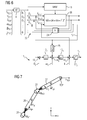
- FIG. 7 shows a concrete example of a 2D robot, with which the possibilities and advantages of the invention can be illustrated.
- the sketched 2D robot has here two arms 26 and 27, which can each be moved by a motor 28, 29.
- At the free end of the second arm 27 is the TCP.
- a force F TCP acts on it in a horizontal direction.
- a weight force F g1 is exerted on the first arm 26 and a weight force F g2 on the second arm.
- the TCP Tool Center Point
- the kinematic relationships for other designated points can be set up, eg. B. for the focal points of the body or the moving swivel.
- the motors and arms are not ideally rigidly connected but via an elastic spring that models the compliance of the drive trains.
- a stiffness matrix K can thus be specified which describes the restoring moments of the springs as a linear reaction to a deflection X.
- the driving moments of the motors, the weight forces of the body and optionally an additional force on the TCP act on the structure. This completes the descriptive system of equations. It describes the connections between movement and forces.
- the springs are stationary and the angular positions of the motor and arm are stationary equal. If forces (for example gravitation F g1 and F g2 or an external force F TCP ) act, the springs are deflected and the angular positions ⁇ M1 and ⁇ M2 of the motors 28 and 29 and the angular positions ⁇ 1 and ⁇ 2 of the arms 26 and 27 are not equal.
- forces for example gravitation F g1 and F g2 or an external force F TCP
- FIG. 8 shows results of simulation calculations, as the position of the robot of FIG. 7 according to a control method according to the prior art (control of the motor position, no compensation).
- the robot is upright in the y-direction according to line 30, when no gravity and no external force are acting on the TCP.
- FIG. 9 shows results of simulation calculations, as the position of the robot of FIG. 7 according to the method of the present invention.
- Line 35 shows the position of the 2D robot in gravity and different values for an external force on the TCP. The robot does not change its position due to the inventive dynamic control, even if the force F TCP changes.
- the system of motion and force equations developed above can be changed according to the forces (given movement) or after the displacement (given forces and moments).
- the number of independent variables is the same in each case (here four).
- the method according to the invention preferably evaluates the equation system Now, in such a way that a part of the motion coordinates (here position of the TCP) and a part of the acting forces is specified and resolved in a targeted manner according to the remaining free sizes (here torque and deflection of the motors).
- FIG. 9 illustrates FIG. 9 in that the structure does not move under the influence of external forces.
- the two motors compensate for the deflection by biasing the compliant drive trains to the required extent (fanned arrows 36 and 37). Both arms stay in the same position.
Abstract
Das dynamische Verhalten von Bewegungen eines Systems mit mehreren, kinematisch zusammenwirkenden Einzelkörpern, von denen mindestens einer von einem Antrieb bewegt wird, soll verbessert werden. Dazu ist eine Vorrichtung zum Steuern und Regeln mit einer Lastrecheneinrichtung (9) zum Berechnen je eines Kraftvektors (f) für jeden der Einzelkörper in Abhängigkeit von vorgegebenen Sollkoordinaten (X TCP , Y TCP , Z TCP , ± TCP , ² TCP , ³ TCP ) fortlaufend während der Bewegung des Systems und einer Momentrecheneinrichtung (10) zum Berechnen mindestens einer die Kraftvektoren kompensierenden Ausgleichsgröße (M) auf der Basis der Sollkoordinaten und der Kraftvektoren fortlaufend während der Bewegung vorgesehen. Außerdem verfügt die Vorrichtung zum Steuern und Regeln über eine Regelungseinheit (11) zum Regeln einer kraftbildenden Größe (i) für den mindestens einen Antrieb in Abhängigkeit von den Sollkoordinaten und dem mindestens einen Ausgleichsdrehmoment fortlaufend während der Bewegung.The dynamic behavior of movements of a system with several kinematically interacting individual bodies, of which at least one is moved by a drive, should be improved. For this purpose, a device for controlling and regulating with a load computing device (9) for calculating a force vector (f) for each of the individual bodies in dependence on predetermined desired coordinates (X TCP, Y TCP, TCP Z, TCP, TCP, TCP) continuously during movement of the system and a moment calculating means (10) for calculating at least one compensating quantity (M) compensating the force vectors on the basis of the desired coordinates and the force vectors continuously during the movement. In addition, the control and regulating device has a control unit (11) for regulating a force-generating variable (i) for the at least one drive as a function of the desired coordinates and the at least one compensating torque continuously during the movement.
Description
Die vorliegende Erfindung betrifft eine Vorrichtung zum Steuern und Regeln einer Bewegung eines Systems mit mehreren, kinematisch zusammenwirkenden Einzelkörpern, von denen mindestens einer ein Antrieb ist. Darüber hinaus betrifft die vorliegende Erfindung ein Verfahren zum Steuern und Regeln einer Bewegung eines solchen Systems. Unter einem derartigen System wird beispielweise eine Anlage, eine Bearbeitungsmaschine, eine Verarbeitungsmaschine und insbesondere auch ein Roboter oder eine Werkzeugmaschine verstanden. Bei dem Antrieb handelt es sich beispielsweise um einen elektrischen Motor oder einen hydraulischen oder pneumatischen Antrieb.The present invention relates to a device for controlling and regulating a movement of a system with a plurality of kinematically interacting individual bodies, of which at least one is a drive. Moreover, the present invention relates to a method for controlling and controlling a movement of such a system. Under such a system is understood, for example, a plant, a processing machine, a processing machine and in particular a robot or a machine tool. The drive is, for example, an electric motor or a hydraulic or pneumatic drive.
Mechanische Systeme dieser Art werden verbreitet in der Fertigung eingesetzt. Eine wichtige Voraussetzung zum Erreichen eines qualitativ guten Ergebnisses ist die absolute Genauigkeit dieser Fertigungsmittel. Jedoch wirken auf mechanische Gebilde externe Störkräfte (z. B. Schwerkraft, Prozesskraft, Reibung, Lastwechsel usw.), die aufgrund der Elastizität der Gelenke und Bauteile (nachfolgend auch Einzelkörper genannt) zu Abweichungen am sogenannten "TCP" (Tool Center Point) führen können. Unter Umständen ist die Stellungsabhängigkeit der Abweichung am TCP aufgrund der Störkräfte sehr stark. So wird beispielsweise ein Roboterarm im ausgestreckten Zustand am freien Ende weiter nach unten gezogen als im eingezogenen oder abgewinkelten Zustand. Ein diesbezügliches Maß ist die absolute statische Genauigkeit.Mechanical systems of this type are widely used in manufacturing. An important prerequisite for achieving a good quality result is the absolute accuracy of these production means. However, external disturbing forces (eg gravity, process force, friction, load changes, etc.) act on mechanical structures, which lead to deviations at the so-called "TCP" (Tool Center Point) due to the elasticity of the joints and components (also referred to below as single bodies) can. Under certain circumstances, the positional dependence of the deviation at the TCP due to the disturbance forces is very strong. For example, a robot arm in the extended state at the free end is further pulled down than in the retracted or angled state. One such measure is the absolute static accuracy.
Diesem Problem der absoluten statischen Genauigkeit wurde bislang dadurch begegnet, dass bei geregelten Achsen ein zweites, direktes Messsystem auf der Lastseite, TCP-nah, eingesetzt wird. Über den Lageregelkreis wird die Stellung des Motors bzw. Antriebs so weit angepasst, dass die notwendige Kompensationskraft über die Antriebsstrangfeder zur Struktur übertragen wird. Der Einsatz eines zweiten Messsystems ist mit erheblichen Zusatzkosten für die Hardware verbunden und erfordert eine aufwendige konstruktive Anpassung für die Anbringung des Messsystems.So far, this problem of absolute static accuracy has been countered by using a second, direct measuring system on the load side, TCP-near, for controlled axes. The position of the motor or drive is adjusted so far via the position control loop that the necessary compensation force via the drive train spring to the structure is transmitted. The use of a second measuring system is associated with considerable additional costs for the hardware and requires a complex structural adaptation for the attachment of the measuring system.
Ein weiterer Ansatz zur Verbesserung der absoluten statischen Genauigkeit besteht darin, bezogen auf eine Referenzposition die Abweichung am TCP in einer Vielzahl an Punkten des Arbeitsraums zu vermessen und als Kompensationswert auf den Sollwertkanal zu addieren bzw. vom Istwertkanal zu subtrahieren. Der Nachteil dieser Methode ist der notwendige Aufwand und die Kosten für die Vermessung des Arbeitsraums bzw. des Roboters/der Maschine. Die Vermessung der Abweichungen erfordert die Bestückung der Anlage mit externen Messmitteln. Das Raster der Messung wird im Einzelfall festgelegt. Die Analyse muss in jeder baugleichen Anlage wiederholt werden. Die tabellarisch hinterlegten Korrekturwerte sind zudem lastabhängig, d.h. sie gelten genau für einen Lastfall. Ändert sich z. B. die Beladung, gelten die Werte nicht mehr.Another approach to improve the absolute static accuracy is based on a reference position to measure the deviation at the TCP in a variety of points of the working space and add as a compensation value to the setpoint channel or to subtract from the actual value channel. The disadvantage of this method is the necessary effort and the cost of measuring the working space or the robot / machine. Measuring the deviations requires equipping the system with external measuring equipment. The grid of the measurement is determined on a case-by-case basis. The analysis must be repeated in each identical system. The tabulated correction values are also load-dependent, i. they apply exactly to a load case. Changes z. As the load, the values are no longer valid.
Hierzu ist aus der Druckschrift
Ein weiteres wichtiges Merkmal ist die sogenannte "quasi-statische Genauigkeit". Während der Beschleunigungsphase wirken gleichermaßen die Motorkraft und Gegenkraft in einem Gelenk. Die Gegenkraft stützt sich auf einem nicht unendlich steifen Gebilde ab und kann durchaus parasitäre Bewegungen am TCP verursachen. Besitzt ein Roboterarm beispielsweise mehrere Glieder, die jeweils mit einem Motor zueinander bewegbar sind (ein Glied mit zugehörigem Antrieb bzw. Motor stellt eine Bewegungsachse, kurz "Achse" dar), so kann sich die Bewegung, insbesondere eine Beschleunigung, des einen Glieds auf das andere auswirken, wodurch die quasi-statische Genauigkeit beeinflusst wird. Hierfür wird bei Werkzeugmaschinen bislang die aufgrund einer Beschleunigung der Leitachse entstandene parasitäre Bewegung mit einem als Lagesollwert aufgeschalteten Kompensationswert kompensiert.Another important feature is the so-called "quasi-static accuracy". During the acceleration phase, the engine power and counterforce act equally in one joint. The counterforce is based on a not infinitely rigid structure and can quite cause parasitic movements on the TCP. For example, if a robot arm has a plurality of links which are each movable with a motor (a link with associated drive or motor represents a motion axis, "axis" for short), then the motion, in particular an acceleration, of one link can be applied to the link affect others, reducing the quasi-static accuracy being affected. For this purpose, in the case of machine tools, the parasitic movement resulting from an acceleration of the leading axis has hitherto been compensated with a compensation value applied as a position setpoint.
Bei der Drehbewegung einer Achse wird vielfach das Moment durch eine sogenannte Momentenvorsteuerung gesteuert. Die Parametrierung der Momentenvorsteuerung erfordert die Eingabe des Achsenträgheitsmoments bezogen auf den Motor. An Industrierobotern ist diese Angabe jedoch aufgrund des Aufbaus nicht über den Arbeitsraum konstant. Die vom Motor aus gesehene Gesamtträgheit ist eine Funktion der Gelenkstellung. Zur Berechung eines Momentensollwerts wird bislang die Motorbeschleunigung mit einem vorbestimmten Wert der Achsenträgheit multipliziert.During the rotational movement of an axis, the torque is often controlled by a so-called torque precontrol. The parameterization of the torque precontrol requires the input of the axis moment of inertia in relation to the motor. On industrial robots, however, this information is not constant over the working space due to the structure. The total inertia seen by the engine is a function of the joint position. To calculate a torque setpoint so far, the engine acceleration is multiplied by a predetermined value of the axial inertia.
Die Parametrierung der maximalen Achsenbeschleunigung erfolgt als Folge der Auslegung des Motors und des Leistungsteils und wird achsenweise aus dem maximal zulässigen Strom und der Achsenträgheit abgeleitet. Da die maximale Beschleunigung als konstanter Wert einzutragen ist, ist für dessen Parametrierung nur die Stelle relevant, wo die auf den Motor bezogene Achsenträgheit ihr Maximum erreicht. Daraus folgt, dass in den Bereichen, wo dieser Wert nicht erreicht wird, die Stromreserve nicht ausgenutzt wird und eine höhere Beschleunigungsgrenze theoretisch möglich wäre. Daher wäre es unter Umständen wünschenswert, eine Beschleunigungsreserve für jede Stellung bzw. eine Anpassung der Beschleunigungsgrenze zur besseren Ausnutzung der Stromgrenze zu berechnen. Bei der Bahnplanung werden positionsabhängige Beschleunigungsgrenzen bislang nicht berücksichtigt.The parameterization of the maximum axis acceleration takes place as a consequence of the design of the motor and the power section and is derived axis-wise from the maximum permissible current and the axis inertia. Since the maximum acceleration is to be entered as a constant value, only the point is relevant for its parameterization, where the axis inertia related to the motor reaches its maximum. It follows that in areas where this value is not reached, the power reserve is not utilized and a higher acceleration limit would theoretically be possible. Therefore, it may be desirable to calculate an acceleration reserve for each position or an adjustment of the acceleration limit for better utilization of the current limit. In path planning, position-dependent acceleration limits have not been considered so far.
Insbesondere bei Industrierobotern wird die Mobilität und Flexibilität des Arbeitsmittels sehr geschätzt. Jedoch erfordert dies konstruktive Randbedingungen, die den Roboter zu einem stark schwingungsanfälligen Gebilde machen. Aufgrund der fehlenden Messmöglichkeiten ist eine elektrische Bedämpfung dieser Schwingung nicht möglich. Ein Teil der Anregung ergibt sich direkt aus den Führungsgrößen. Daher sollte hinsichtlich der Schwingungen das Führungsverhalten entsprechend angepasst sein. Eine mögliche Abhilfe besteht darin, den Frequenzinhalt der Fahrprofile durch eine Reduzierung des Rucks so zu entschärfen, dass Eigenresonanzen nicht mehr angeregt werden. Der Nachteil dieser Methode ist die zum Teil starke notwendige Einschränkung der Achsendynamik.Especially in industrial robots, the mobility and flexibility of the work equipment is much appreciated. However, this requires design constraints that make the robot a highly susceptible structure. Due to the lack of measurement options, an electrical damping of this vibration is not possible. Part of the suggestion results directly from the reference variables. Therefore, with regard to the vibrations, the leadership behavior should be adjusted accordingly. A possible remedy is to defuse the frequency content of the driving profiles by reducing the jerk so that natural resonances are no longer stimulated. The disadvantage of this method is the sometimes strong necessary restriction of the axis dynamics.
Aufgrund der zum Teil komplexen Bewegungstransformation und der sich daraus ergebenden Ausgleichsbewegungen ist es keine triviale Aufgabe, im Vorfeld Kollisionsgefahren zu identifizieren. Auch eine Überwachung von Messsignalen (z. B. Motorstrom) ist aufgrund der zum Teil stark variablen Belastung nicht möglich. Eine verbesserte Kollisionsüberwachung wäre also erstrebenswert. Bei bislang bekannten Lösungsansätzen hierzu werden die mittels eines Modells berechneten Motorströme mit den real gemessenen Motorströmen verglichen, und bei unzulässig großen Abweichungen wird die Maschine/der Roboter gestoppt. Ein solches System ist beispielsweise aus der Druckschrift
Die Aufgabe der vorliegenden Erfindung besteht somit darin, eine Vorrichtung zum Steuern und Regeln und ein entsprechendes Verfahren zum Steuern und Regeln einer Bewegung eines Systems mit mehreren, kinematisch zusammenwirkenden Einzelkörpern vorzuschlagen, bei denen die Bewegung des Systems als solche genauer ausgeführt werden kann.The object of the present invention is thus to propose a device for controlling and a corresponding method for controlling and regulating a movement of a system with a plurality of kinematically interacting individual bodies, in which the movement of the system as such can be carried out more accurately.
Erfindungsgemäß wird diese Aufgabe gelöst durch eine Vorrichtung zum Steuern und Regeln einer Bewegung eines Systems mit mehreren, kinematisch zusammenwirkenden Einzelkörpern, von denen mindestens einer von einem Antrieb bewegbar ist, umfassend
- eine Lastrecheneinrichtung zum Berechnen je eines Kraftvektors für jeden der Einzelkörper in Abhängigkeit von vorgegebenen Sollkoordinaten fortlaufend während der Bewegung des Systems,
- eine Momentrecheneinrichtung zum Berechnen mindestens einer die Kraftvektoren kompensierenden Ausgleichsgröße auf der Basis der Sollkoordinaten und der Kraftvektoren fortlaufend während der Bewegung und
- eine Regelungseinheit zum Regeln einer kraftbildenden Größe für den mindestens einen Antrieb in Abhängigkeit von den Sollkoordinaten und der mindestens einen Ausgleichsgröße fortlaufend während der Bewegung.
- a load calculating device for calculating a force vector for each of the individual bodies in dependence on predetermined desired coordinates continuously during the movement of the system,
- a moment calculating means for calculating at least one compensating quantity compensating the force vectors on the basis of the target coordinates and the force vectors continuously during the movement and
- a control unit for regulating a force-generating variable for the at least one drive in dependence on the desired coordinates and the at least one compensating variable continuously during the movement.
Darüber hinaus wird erfindungsgemäß bereitgestellt ein Verfahren zum Steuern und Regeln einer Bewegung eines Systems mit mehreren, kinematisch zusammenwirkenden Einzelkörpern, von denen mindestens einer von einem Antrieb bewegbar ist, durch
- Berechnen je eines Kraftvektors für jeden der Einzelkörper in Abhängigkeit von vorgegebenen Sollkoordinaten fortlaufend während der Bewegung des Systems,
- Berechnen mindestens einer die Kraftvektoren kompensierenden Ausgleichsgröße auf der Basis der Sollkoordinaten und der Kraftvektoren fortlaufend während der Bewegung und
- Regeln einer kraftbildenden Größe für den mindestens einen Antrieb in Abhängigkeit von den Sollkoordinaten und der mindestens einen Ausgleichsgröße fortlaufend während der Bewegung.
- Calculating one force vector for each of the individual bodies as a function of predetermined desired coordinates continuously during the movement of the system,
- Calculating at least one compensation value compensating the force vectors on the basis of the desired coordinates and the force vectors continuously during the movement and
- Controlling a force-generating variable for the at least one drive in dependence on the desired coordinates and the at least one compensating variable continuously during the movement.
Im Falle eines elektrischen Motors als Antrieb handelt es sich bei der kraftbildenden Größe um den elektrischen Strom, während die kraftbildende Größe bei einem hydraulischen oder pneumatischen Antrieb der Druck ist.In the case of an electric motor as drive, the force-generating variable is the electric current, while the force-generating variable is the pressure in a hydraulic or pneumatic drive.
In vorteilhafter Weise wird also die Bewegung des Systems fortlaufend dynamisch geregelt. Es werden also ständig während der Bewegung Kraftvektoren und entsprechende Ausgleichsgrößen neu berechnet, so dass eine vorgegebene Bewegungsbahn besser eingehalten werden kann. Die genaue Einhaltung von Bewegungsbahnen ist bei vielen Fertigungsaufgaben notwendig, nicht jedoch bei den meisten Pick-and-Place-Aufgaben, bei denen bekannte Lösungen gemäß
Die Ausgleichsgröße kann ein Ausgleichsdrehmoment, eine Ausgleichskraft, eine Ausgleichsgeschwindigkeit oder eine Ausgleichsposition sein. Somit kann jede dieser Größen einzeln oder in Kombination zum Ausgleich herangezogen werden. Bei kaskadierter Regelung führt eine Steuerung mit dem Ausgleichsdrehmoment als Ausgleichsgröße zu einer rascheren Kompensation der Störkräfte. Eine Steuerung mit der Ausgleichsposition als Ausgleichsgröße führt zu einer genaueren Kompensation der Störkräfte.The compensation quantity may be a compensation torque, a compensation force, a compensation speed or a compensation position. Thus, each of these sizes can be used individually or in combination to compensate. In the case of cascaded control, a control with the compensation torque as compensating variable leads to a more rapid compensation of the disturbing forces. A control with the compensation position as a compensation variable leads to a more precise compensation of the disturbing forces.
Vorzugsweise zieht die Lastrecheneinrichtung zum Berechnen des jeweiligen Kraftvektors ein Lastmodell heran, in dem eine Stelle und/oder Richtung und/oder Amplitude einer Krafteinleitung in einen der Einzelkörper berücksichtigt ist/sind. Auf diese Weise kann die Krafteinleitung mit all ihren Parametern dynamisch während einer Bewegung berücksichtigt werden.For calculating the respective force vector, the load calculating device preferably draws on a load model in which a location and / or direction and / or amplitude of a force introduction into one of the individual bodies is / are taken into account. In this way, the force introduction with all its parameters can be considered dynamically during a movement.
Besonders vorteilhaft ist außerdem, wenn die Regelungseinheit eine kaskadierte Lageregelung, Geschwindigkeitsregelung und Stromregelung (bzw. Regelung der kraftbildenden Größe) aufweist. Hierdurch kann die Bewegung des Systems in allen Einzelheiten exakt geregelt werden.In addition, it is particularly advantageous if the control unit has a cascaded position control, speed control and current control (or regulation of the force-generating variable). This allows the movement of the system to be precisely controlled in all its details.
Günstigerweise zieht die Momentrecheneinrichtung zum Berechnen des mindestens einen Ausgleichsmoments ein Mehrkörpermodell heran, in dem eine Masse und/oder eine Elastizität und/oder eine Dämpfung und/oder eine lineare Abhängigkeit von Freiheitsgraden jeweils jedes der Einzelkörper berücksichtigt ist/sind. Auf diese Weise können alle oder die wichtigsten mechanischen Größen bei der Modellierung des Systems berücksichtigt werden.Conveniently, the moment-calculating device for calculating the at least one balancing torque uses a multi-body model in which a mass and / or an elasticity and / or a damping and / or a linear dependence on degrees of freedom of each of the individual bodies is / are taken into account. In this way, all or the most important mechanical quantities can be taken into account when modeling the system.
Speziell kann das Mehrkörpermodell auf einem linearen Differenzialgleichungssystem beruhen. Dies hat den Vorteil, dass es ohne hohen Rechenaufwand gelöst werden kann.Specifically, the multi-body model may be based on a linear differential equation system. This has the advantage that it can be solved without high computational effort.
Insbesondere ist es vorteilhaft, wenn das Differenzialgleichungssystem auf einer Massenmatrix, einer Dämpfungsmatrix und einer Steifigkeitsmatrix jeweils bezogen auf die Einzelkörper beruht. Damit gehen die wesentlichen mechanischen Größen wie Masse, Dämpfung und Steifigkeit in das Mehrkörpermodell ein.In particular, it is advantageous if the differential equation system is based on a mass matrix, a damping matrix and a stiffness matrix in each case based on the individual bodies. Thus, the major mechanical parameters such as mass, damping and stiffness enter the multi-body model.
Ferner können in dem Mehrkörpermodell Trägheitskräfte (gegebenenfalls auch die Corioliskraft) und/oder Kreiselkräfte, die jeweils auf die Einzelkörper wirken, berücksichtig sein. Dadurch lässt sich insbesondere die quasi-statische Genauigkeit der Bewegung erhöhen.Furthermore, in the multi-body model, inertial forces (possibly also the Coriolis force) and / or centrifugal forces, which respectively act on the individual bodies, can be taken into account. As a result, in particular the quasi-static accuracy of the movement can be increased.
Bei einer weiteren Ausführungsform ist mit der Momentrecheneinrichtung eine maximale Beschleunigung eines der Einzelkörper oder eines Verbunds mehrerer der Einzelkörper fortlaufend während der Bewegung berechenbar. Dies hat den Vorteil, dass in jeder Stellung die Beschleunigungsgrenze zur besseren Ausnutzung der Stromgrenze bzw. Druckgrenze angepasst werden kann.In a further embodiment, with the moment-calculating device, a maximum acceleration of one of the individual bodies or of a composite of a plurality of the individual bodies can be calculated continuously during the movement. This has the advantage that in each position, the acceleration limit can be adapted to better use of the current limit or pressure limit.
Bei einer weiteren Ausführungsform sind die Momenteneinrichtung und die Regeleinheit dazu ausgelegt, dass sie fortlaufend während der Bewegung die Anregung mindestens einer Eigenfrequenz des Systems reduzieren. Dies bedeutet, dass die Eigenfrequenzen weniger angeregt werden, was zu einem besseren Bewegungsverhalten des Systems führt.In a further embodiment, the torque device and the control unit are designed so that they continuously reduce the excitation of at least one natural frequency of the system during the movement. This means that the natural frequencies are less excited, which leads to a better movement behavior of the system.
Die Vorrichtung zum Steuern und Regeln kann ein Modell der Regelstrecke des Systems aufweist, wobei mit dem Modell mindestens eine ideale Führungsgröße für den Antrieb berechenbar ist. Damit kann eine bestimmbare Dynamik für die Achsen vorgegeben werden.The device for controlling and regulating may have a model of the controlled system of the system, wherein at least one ideal reference variable for the drive can be calculated with the model. This allows a definable dynamic for the axes to be specified.
Bei einer weiteren Ausführungsform kann die Vorrichtung zum Steuern und Regeln ein Modell der Regelstrecke des Systems aufweisen, wobei mit dem Modell ein ideales Drehmoment des Antriebs zur Überwachung eines Istdrehmoments des Antriebs berechenbar ist. Mit einem solchen Modell der Regelstrecke lassen sich beispielsweise Antriebmomente des realen Systems überwachen, wodurch auf Kollisionen zurückgeschlossen werden kann.In a further embodiment, the control and regulating device may comprise a model of the controlled system of the system, the model having an ideal torque of the drive for monitoring an actual torque of the drive is calculable. With such a model of the controlled system, for example, drive torques of the real system can be monitored, as a result of which collisions can be deduced.
Die oben im Zusammenhang mit der erfindungsgemäßen Vorrichtung zum Steuern und Regeln geschilderten weiterbildenden Funktionen lassen sich auch als Verfahrensschritte in das erfindungsgemäße Verfahren integrieren.The further-forming functions described above in connection with the device according to the invention for controlling and regulating can also be integrated into the method according to the invention as method steps.
Die vorliegende Erfindung wird nun anhand der beigefügten Zeichnungen näher erläutert, in denen zeigen:
- FIG 1
- eine graphische Darstellung eines Modells eines Industrieroboters;
- FIG 2
- eine strukturelle Übersicht einer Störkraftkompensation;
- FIG 3
- eine strukturelle Übersicht einer Kompensation der aufgrund einer quasi-statischen Kraft entstehenden parasitären Bewegung;
- FIG 4
- eine strukturelle Übersicht der Momentenvorsteuerung;
- FIG 5
- eine strukturelle Übersicht der Vorsteuerung mit Sollwertfilter;
- FIG 6
- eine strukturelle Übersicht der Vorsteuerung mit modellbasierter Zustandsregelung;
- FIG 7
- ein Simulationsbeispiel mit einem 2D-Roboter;
- FIG 8
- die Auslenkung des Roboters von
FIG 7 gemäß dem Stand der Technik; und - FIG 9
- die Auslenkung des Roboters von
FIG 7 mit erfindungsgemäßer modellbasierter Kraftkompensation.
- FIG. 1
- a graphical representation of a model of an industrial robot;
- FIG. 2
- a structural overview of a Störkraftkompensation;
- FIG. 3
- a structural overview of a compensation of the resulting due to a quasi-static force parasitic motion;
- FIG. 4
- a structural overview of the torque precontrol;
- FIG. 5
- a structural overview of the pilot control with setpoint filter;
- FIG. 6
- a structural overview of precontrol with model-based state control;
- FIG. 7
- a simulation example with a 2D robot;
- FIG. 8
- the deflection of the robot from
FIG. 7 according to the prior art; and - FIG. 9
- the deflection of the robot from
FIG. 7 with inventive model-based force compensation.
Die nachfolgend näher geschilderten Ausführungsbeispiele stellen bevorzugte Ausführungsformen der vorliegenden Erfindung dar.The embodiments described in more detail below represent preferred embodiments of the present invention.
Für ein beliebig ausgestaltetes System (Maschine, Anlage, etc.) der eingangs genannten Art, insbesondere einen Roboter oder eine Werkzeugmaschine, kann eine Vorrichtung zum Steuern und Regeln der Bewegung seiner mehreren, kinematisch zusammenwirkenden Einzelkörper verwendet werden. Ein Beispiel eines solchen Mehrkörpersystems ist in
Der Roboterkörper 2 stellt zusammen mit dem Motor 3 eine Bewegungsachse (kurz: Achse) dar. An dem Roboterkörper 2 ist ein erster Arm 4 mittels eines Motors 5 drehbar gelagert. Am distalen Ende dieses ersten Arms 4 ist ein zweiter Arm 6 mittels eines weiteren Motors 7 ebenfalls drehbar gelagert. Der Roboter besitzt also hier drei Achsen, von denen die erste Achse mit dem Einzelkörpern 2 (ggf. einschließlich Motor 3), die zweite Achse mit dem Einzelkörpern 4 (ggf. einschließlich Motor 5) und die dritte Achse mit den Einzelkörpern 6 (ggf. einschließlich Motor 7) gebildet ist.The
Bewegt sich mindestens eine dieser Achsen, so wird hier von einer Bewegung des Systems gesprochen. Jede Achse bzw. jeder Einzelkörper besitzt jeweils seine individuelle Masse, Dämpfung, Steifigkeit etc. Dies führt dazu, dass sich beispielsweise die Schwerkraft oder eine Prozesskraft unterschiedlich auf das System auswirkt, je nachdem, in welcher Stellung die Achsen zueinander stehen. Wenn beispielsweise an der Spitze des in
Das Verhalten des Systems kann in einem Mehrkörpermodell beschrieben werden, das ein dreidimensionales, mechanisches MIMO-Modell (Multiple Input, Multiple Output) darstellt.The behavior of the system can be described in a multi-body model representing a three-dimensional mechanical MIMO (multiple input, multiple output) model.
Eine Vorrichtung zum Steuern und Regeln (dies und folgendes gilt sinngemäß auch für ein entsprechendes Verfahren) gemäß der vorliegenden Erfindung zum Regeln einer Bewegung eines Systems wie dem Roboter von
- Masseneigenschaften der einzelnen Körper und Massenverhalten im Raum,
- Elastizität der Gelenke und Antriebsstränge; gegebenenfalls könnte die Elastizität der Körper einbezogen werden,
- lineare Dämpfungseigenschaften der Federelemente,
- geometrische Zwangsbedingungen bzw. lineare Abhängigkeiten zwischen einzelnen Freiheitsgraden und
- Definition der Gelenke (Typ, Lage und Ausrichtung).
- Mass properties of individual bodies and mass behavior in space,
- Elasticity of the joints and drive trains; if necessary, the elasticity of the bodies could be included,
- linear damping properties of the spring elements,
- geometric constraints or linear dependencies between individual degrees of freedom and
- Definition of the joints (type, position and orientation).
Sowohl das statische als auch das dynamische Übertragungsverhalten zwischen Ein- und Ausgängen kann mit Hilfe des folgenden linearen Differenzialgleichungssystems beschrieben werden: ![]()
![]()
Dabei bedeuten M die Massenmatrix, D die Dämpfungsmatrix, K die Steifigkeitsmatrix und T die rechteckige Transformationsmatrix, die die Beziehung zwischen den Zustandsgrößen X und allen Freiheitsgraden des Modells wiedergibt. Jeder Einzelkörper des Systems (vgl. Bezugszeichen 1, 2, 4 und 6 von
Das Modell ist vorzugsweise ein lineares Mehrkörpersystem, bei dem die Stellungsabhängigkeit des Systemverhaltens berücksichtigt wird. Eine verbesserte absolute Genauigkeit kann nämlich dadurch erreicht werden, dass zu jedem Zeitpunkt Motorkräfte zur Kompensation aller Störkräfte eingeleitet werden. Daraus ergibt sich ein Gleichgewichtszustand, in dem die kleinen Abweichungen am TCP null sind.The model is preferably a linear multibody system that takes into account the positional dependence of the system behavior. An improved absolute accuracy can namely be achieved in that at any time engine forces to compensate for all disturbing forces are initiated. This results in an equilibrium state in which the small deviations at the TCP are zero.
Eine wichtige Voraussetzung für die Berechnung der Motormomente ist die genaue Kenntnis des Lastfalls. Die Beschreibung des Lastfalls beinhaltet Informationen über die Stelle(n), die Richtung(en) und die Amplitude(n) der Krafteinleitung. Als Kraft werden neben den genannten Störkräften auch Bearbeitungskräfte eingeleitet, wie sie beispielsweise beim Fräsen oder Bohren entstehen.An important prerequisite for the calculation of the engine torque is the exact knowledge of the load case. The description of the load case contains information about the location (s), the direction (s) and the amplitude (s) of the force application. As a force, in addition to the aforementioned disturbing forces and machining forces are introduced, as they arise, for example, when milling or drilling.
Die Motormomente und die Stellungen der Einzelkörper (z.B. Roboterarme) sind dann Lösung des folgenden statischen Gleichungssystems: ![]()

![]()
Die Matrix TTCP ist ein Auszug aus der Matrix T und beschreibt die lineare Abhängigkeit zwischen den Koordinaten des TCP und den Zustandsgrößen. Eine wichtige Voraussetzung für die Lösbarkeit des Problems ist, dass alle zu null deklarierten TCP-Koordinaten von den Motoren bewegbar sind. Dies ist jedoch bei allen hier betrachteten Maschinen- und Roboter-Kinematiken der Fall. Der Roboter muss also das jeweilige Werkzeug in die gewünschte Richtung auch bewegen können.The matrix T TCP is an excerpt from the matrix T and describes the linear dependence between the coordinates of the TCP and the state variables. An important prerequisite for the solvability of the problem is that all zeros declared TCP coordinates are movable by the motors. However, this is the case for all machine and robot kinematics considered here. The robot must therefore be able to move the respective tool in the desired direction.
Die Übertragung des Motormoments zur mechanischen Struktur erfordert das Aufspannen der Antriebsstrangfeder durch einen Winkelversatz am Motor. Dieser Winkelversatz wird aus dem Zustandsvektor X abgeleitet und muss bei der Sollwertgenerierung berücksichtigt werden.The transmission of the engine torque to the mechanical structure requires the tensioning of the drive train spring by an angular offset on the engine. This angular offset is derived from the state vector X and must be taken into account in the setpoint generation.
Ein Mehrkörpermodell 10 (MKM; ggf. realisiert als Momentrecheneinrichtung) verarbeitet die Kraftvektoren bzw. den Kraftvektor f weiter. Auf seiner Basis und der Basis der Gelenkkoordinaten wird je ein Motormoment bzw. ein entsprechendes Stromäquivalent für den jeweiligen Motor jeder Achse berechnet. Außerdem werden in dem Mehrkörpermodell 10 hier auch Winkelversätze Δθ berechnet. Bei diesen Berechnungen werden die Masseneigenschaften, die Elastizität, die Dämpfung und lineare Abhängigkeiten der Freiheitsgrade der jeweiligen Achsen bzw. Einzelkörper berücksichtigt. Vorzugsweise beruht das Mehrkörpermodell 10 auf dem linearen Differenzialgleichungssystem zweiter Ordnung, das oben vorgestellt wurde.A multi-body model 10 (MKM, possibly implemented as a moment-calculating device) processes the force vectors or the Force vector f further. On its basis and the basis of the joint coordinates, an engine torque or a corresponding current equivalent is calculated for the respective motor of each axle. In addition, in the
Eine dem Mehrkörpermodell 10 nachgeschaltete Regelungseinheit 11 ermittelt aus den Gelenkkoordinaten θ1, θ2, θ3, ..., θi, ..., θn, den Winkelversätzen Δθ und den Motormomenten M einen Strom i zum Ansteuern eines in
Die Stellgröße des Lagereglers 12 dient als Eingangsgröße für eine nachgeschaltete Geschwindigkeitsregelung, wobei dieser Eingangsgröße eine Istwinkelgeschwindigkeit ωj in einem Addierer 14 vorzeichenrichtig aufsummiert wird. Das Summensignal wird einem Geschwindigkeitsregler 15 (vorzugsweise ein PI-Regler) zugeführt.The manipulated variable of the
Das Ausgangssignal der Geschwindigkeitsregelung bzw. des Geschwindigkeitsreglers 15 dient als Eingangsgröße für eine Stromregelung. Dieser Eingangsgröße wird in einem Addierer ein jeweiliges Motormoment M bzw. ein entsprechendes Äquivalent sowie ein Iststrom Ij vorzeichenrichtig in einem Addierer 16 aufaddiert. Dieser Addierer 16 wie auch die anderen beiden Addierer 13 und 14 (allgemein: Verknüpfungselemente) besitzen gegebenenfalls eine Umrechnungs- bzw. Verstärkungsfunktionalität, um die jeweils gewünschte Größe beispielsweise durch Multiplikation zu erhalten. Das Ausgangssignal des Addierers 16 wird einem Stromregler 17 zugeführt, der die Stellgröße für den Motor, nämlich den Strom i ausgibt.The output signal of the speed control or the
Der Übersichtlichkeit halber ist in
Weiterhin kann das Mehrkörpermodell verwendet werden, um quasi-statische Lastfälle sowie Beschleunigungsvorgänge zu kompensieren. Die Beschleunigung einer Achse und die dadurch erzeugte Gegenkraft im Gelenk können gegebenenfalls aufgrund der Nachgiebigkeit des Gebildes zu parasitären Bewegungen am TCP führen. Wenn sich beispielsweise eine beschleunigte Achse auf einer zweiten Achse abstützt, ändert die zweite Achse aufgrund ihrer endlichen Steifigkeit ihre Position oder Neigung. Solche und ähnliche parasitären Bewegungen können mit Hilfe von Ausgleichsbewegungen der restlichen Achsen kompensiert werden. In dem Fall wird die berechnete Ausgleichsbewegung als Drehzahl und Drehmoment vorgesteuert. Eine solche Vorsteuerung ist für n Achsen A1, A2, ..., Ai, ..., An in
Wie erwähnt, ist in
Alle n Regelungseinheiten 111 bis 11n sind strukturell gleich aufgebaut. Daher wird hier lediglich die erste Regelungseinheit 111 im Detail beschrieben. Sie basiert auf der Regelungseinheit 11 von
Weiterhin kann aus dem Mehrkörpermodell 10 für jede Stellung die auf den jeweiligen Motor bezogene Achsenträgheit berechnet werden. Die Achsenträgheit wird hierzu aus der mit dem Starrkörpermode (Eigenfrequenz 0 Hz) assoziierten modalen Masse ermittelt. Dieser Starrkörpermode ist rein theoretischer Natur und bezeichnet eine Bewegung ohne jegliche Schwingung. Für die Berechnung muss also jeweils nur ein Motor sich frei bewegen dürfen. Die restlichen Achsen sind jeweils geklemmt. Zur Berechnung der modalen Masse ist es hinreichend, nur den dem Starrkörpermode assoziierten Eigenvektor zu kennen. Die Pseudo-Inversion des Eigenvektors ist trivial und ist für den Rechenprozess weniger belastend als die Inversion einer kompletten Matrix.Furthermore, from the
Die Bestimmung des zum Starrkörpermode assoziierten Eigenvektors kann auf einfache Weise erfolgen, ohne Betrachtung der restlichen Eigenwerte und -vektoren. Die Methodik wird am Beispiel einer beliebigen quadratischen Matrix A erklärt. Für die Matrix A sind die Eigenwerte λ und die dazugehörigen Eigenvektoren Xλ die Lösungen des folgenden Gleichungssystems: ![]()
![]()
Für die genannte Aufgabenstellung darf angenommen werden, dass die Matrix A nur einen einzigen Starrkörpermode besitzt. Dies bedeutet, dass für λ=0 der Lösungsraum ein eindimensionaler Vektorraum ist. Die Bestimmung des Basisvektors erfordert die Lösung eines einfachen Gleichungssystems: ![]()
![]()
Die Lösung des linearen Gleichungssystems kann beispielsweise mit Hilfe des Algorithmus "eigen" optimiert werden. Das Ergebnis ist der gesuchte Eigenvektor Xλ: 
Für die Berechnung der modalen Massen wird der pseudo-inverse Vektor Xiλ benötigt. Der Vektor kann elementweise konstruiert werden. Xiλ erfüllt folgende Bedingung: Xiλ TXλ=1. 
Und n0 die Anzahl an Elementen des Vektors Xλ ungleich null.And n 0 is the number of elements of the vector X λ nonzero.
Für die Bestimmung der modalen Masse wird die Matrix, deren Starrkörpermode gesucht wird (A), aus folgendem Differenzialgleichungssystem abgeleitet: 
Das Gleichungssystem für die Bestimmung des Eigenvektors lautet in dem Fall: 
Die Gesamtträgheit wird aus den berechneten Größen abgeleitet: ![]()
![]()
Das Mehrkörpermodell kann also dazu verwendet werden, für jede Stellung die auf die Motoren bezogenen Achsenträgheiten JMot zur Parametrierung der Momentenvorsteuerung zu berechnen. Daher besitzt das Mehrkörpermodell 10 in
Das obige Mehrkörpermodell, das vorzugsweise auf dem genannten linearen Differenzialgleichungssystem beruht, kann, wie oben dargelegt wurde, zur Berechnung der auf die jeweiligen Motoren bezogenen Achsenträgheiten für jede Stellung verwendet werden. Daraus können dann in einem gegebenenfalls erweiterten Modell maximale Achsenbeschleunigungen bestimmt werden. Die jeweils aktuelle maximale Achsenbeschleunigung während der Bewegung des Systems hat durchaus Einfluss auf den Verlauf der Bewegung.The above multi-body model, which is preferably based on the said linear differential equation system, can, as stated above, for the calculation of the respective Motors related axis inertia can be used for each position. From this, maximum axis accelerations can then be determined in an optionally extended model. The current maximum axis acceleration during the movement of the system definitely has an influence on the course of the movement.
Anhand der vom Modell beschriebenen dynamischen Eigenschaften können die Führungsgrößen so angepasst werden, dass die Anregung der Eigenfrequenzen vermieden wird. Dafür können verschiedene Verfahren eingesetzt werden:
- Lagesollwertfilter, dessen Eigenschaften aus dem Modell (d.h. Mehrkörpermodell) abgeleitet werden (z. B. Nullstellen; vgl.
FIG 5 ) und - Entwurf einer mehrdimensionalen Zustandsregelung für das Modell und Vorsteuerung der dadurch entstehenden Stellgrößen (vgl.
FIG 6 ).
- Position setpoint filter whose properties are derived from the model (ie multi-body model) (eg zeros;
FIG. 5 ) and - Design of a multi-dimensional state control for the model and precontrol of the resulting manipulated variables (cf.
FIG. 6 ).
Die Abbildung von
Im Unterschied zu den vorausgehenden Ausführungsformen ist hier ein Sollwertfilter 21 vorgesehen (SWF). Dieser erhält als Eingangssignal nicht nur eine Lageinformation über die Gelenkkoordinaten θ1 bis θn direkt, sondern auch ein mittels eines Differenzierers 22 daraus gebildetes Geschwindigkeitssignal und mittels eines Zweifachdifferenzierers 23 daraus gebildetes Beschleunigungssignal. Aus diesen drei Signalen bildet das Sollwertfilter 21 ein gefiltertes Beschleunigungssignal, welches der Verknüpfungseinheit 20 zugeführt wird, welche ihrerseits das gefilterte Beschleunigungssignal mit der vom Mehrkörpermodell 10 gelieferten Achsengesamtträgheit JMot und ein entsprechendes Resultat dem Addierer 16 für die Stromregelung als Führungsgröße zur Verfügung stellt. Neben dieser Vorsteuerung des Stroms für die Stromregelung wird die Geschwindigkeitsregelung mit einem gefilterten Geschwindigkeitssignal, das das Sollwertfilter 21 aus den einfach differenzierten Gelenkkoordinaten gewinnt, vorgesteuert. Dazu wird das gefilterte Geschwindigkeitssignal in den Addierer 14 eingegeben.In contrast to the preceding embodiments, a
Schließlich erfolgt eine Vorsteuerung bzw. Führung der Lageregelung durch ein gefiltertes Lagesignal, das das Sollwertfilter 21 von den Gelenkkoordinaten θ1 bis θn erhält. Dieses gefilterte Lagesignal wird dem Addierer 13 als Führungsgröße zugeführt.Finally, precontrol or guidance of the position control takes place by means of a filtered position signal which receives the
Mit dem Sollwertfilter 21 können dann spezielle Eigenfrequenzen des Systems stellungsabhängig, d.h. jeweils zeitlich aktuell während der Beschleunigung, ausgefiltert werden. So ändern sich beispielsweise die Eigenfrequenzen eines Roboters, wenn er seine Armstellung verändert. Im ausgestreckten Zustand des Arms sind nämlich die Eigenschwingungen langsamer als im angezogenen Zustand des Arms. Somit kann auch während einer Bewegung vorab auf die Eigenfrequenzen des Roboters reagiert werden. So werden beispielsweise Frequenzen bei 15 Hz ausgefiltert, wenn der Roboter den Arm ausgestreckt hat und Frequenzen bei 17 Hz ausgefiltert, wenn der Arm eine Zwischenstellung einnimmt, und Frequenzen bei 20 Hz ausgefiltert, wenn der Arm angezogen ist.With the
Eine weitere Möglichkeit zur Anpassung der Führungsgrößen ist in dem Ausführungsbeispiel von
Ergänzend sei noch bemerkt, dass das Mehrkörpermodell 10 jeweils die momentan gültigen Matrizen M, D und K an das Modell 38 einliefert.In addition, it should be noted that the
Darüber hinaus werden die in der idealen Regelung 39 rückgeführten Größen zusammen mit den Gelenkkoordinaten zu den Stellgrößen FMot1, FMot2, FMot3 bis FMotn, die jeweils Kräfte darstellen, der Regelstrecke verknüpft.In addition, the quantities recirculated in the
Ein Modell der realen Strecke kann somit dazu verwendet werden, um eine Anpassung der Führungsgrößen der realen Regelungseinheit zur Reduzierung der Anregung der Eigenfrequenzen durchzuführen.A model of the real distance can thus be used to perform an adaptation of the reference variables of the real control unit to reduce the excitation of the natural frequencies.
Bei der Berücksichtigung aller erwarteten Lastfälle und der Verwendung einer richtigen Momentenvorsteuerung steht zu jedem Zeitpunkt eine passende Abschätzung der Motormomente zur Verfügung, die zu Überwachungszwecken weiter verwendet werden kann. Eine signifikante Abweichung des gemessenen Motormoments bzw. des Iststromwerts Ii vom berechneten Motormoment, das von der Regelstrecke bzw. dem Modell 38 ausgegeben wird, würde auf ein unerwartetes Ereignis (z. B. eine Kollision) hinweisen. Das Modell 38 kann also außer zur Anpassung der Führungsgrößen auch zur Überwachung der Motormomente verwendet werden.Taking into account all expected load cases and the use of correct torque precontrol, a suitable estimation of the engine torques is available at all times, which can be used for monitoring purposes. A significant deviation of the measured engine torque or actual current value I i from the calculated engine torque output by the controlled system or the
Im Allgemeinen besitzt jeder der vier Körper 26 bis 29 sechs Freiheitsgrade. Da dies ein zweidimensonales, mechanisches Problem ist, genügen drei Koordinaten pro Körper zur vollständigen Beschreibung. Die Kinematik unterliegt des Weiteren folgenden Zwangsbedingungen:
Arm 26 ist drehbar gegenüber dem Untergrund gelagert.Arm 27 istdrehbar gegenüber Arm 26 gelagert.Motor 28 kann sich relativ zum Untergrund nur drehen.Motor 29 wirdmit Arm 26 mitbewegt und kann sich relativ zuArm 26 nur drehen.
-
Arm 26 is rotatably mounted relative to the ground. -
Arm 27 is rotatably supported relative toarm 26. -
Motor 28 can only rotate relative to the ground. -
Motor 29 is moved witharm 26 and can rotate relative toarm 26 only.
Die Lagebedingungen schränken die Bewegungsmöglichkeiten ein und werden als lineare Abhängigkeiten zwischen den Freiheitsgraden formuliert. Damit hat der 2D-Roboter nur noch vier unabhängige Bewegungsgrößen. Dies wird in
Der TCP (Tool Center Point) ist der für die Bewegung relevante Bezugspunkt. Die Koordinatentransformation zwischen der kartesischen Position des TCP und den Stellungen der Arme lautet: 
Ebenso lassen sich die kinematischen Beziehungen für andere ausgewiesene Punkte aufstellen, z. B. für die Schwerpunkte der Körper oder das bewegte Drehgelenk. In linearisierter Darstellung (Jacobimatrix) bilden diese die Einträge der Transformationsmatrix T zur Umrechnung der Koordinaten.Likewise, the kinematic relationships for other designated points can be set up, eg. B. for the focal points of the body or the moving swivel. In a linearized representation (Jacobian matrix) these form the entries of the transformation matrix T for the conversion of the coordinates.
Die Linearisierung der Mechanik-Gleichungen erfolgt in einem gegebenen Betriebspunkt. Diese Referenzposition ist für den Moment "eingefroren". Der Zustandsvektor X enthält nun die Auslenkung der Struktur aus diesem Arbeitspunkt.The linearization of the mechanical equations takes place at a given operating point. This reference position is "frozen" for the moment. The state vector X now contains the deflection of the structure from this operating point.
Die Motoren und die Arme sind nicht ideal steif verbunden, sondern über eine elastische Feder, die die Nachgiebigkeit der Antriebsstränge modelliert. Für einen Arbeitspunkt kann somit eine Steifigkeitsmatrix K angegeben werden, die die Rückstellmomente der Federn als lineare Reaktion auf eine Auslenkung X beschreibt.The motors and arms are not ideally rigidly connected but via an elastic spring that models the compliance of the drive trains. For a working point, a stiffness matrix K can thus be specified which describes the restoring moments of the springs as a linear reaction to a deflection X.
Auf die Struktur wirken die Antriebsmomente der Motoren, die Gewichtskräfte der Körper und gegebenenfalls eine zusätzliche Kraft am TCP. Damit ist das beschreibende Gleichungssystem vollständig. Es beschreibt die Zusammenhänge zwischen Bewegung und Kräften.The driving moments of the motors, the weight forces of the body and optionally an additional force on the TCP act on the structure. This completes the descriptive system of equations. It describes the connections between movement and forces.
Wirken keine äußeren Kräfte, so sind die Federn stationär entspannt und die Winkellagen von Motor und Arm sind jeweils gleich. Wirken Kräfte (z. B Gravitation Fg1 und Fg2 oder eine externe Kraft FTCP), so werden die Federn ausgelenkt und die Winkellagen ϕM1 und ϕM2 der Motoren 28 und 29 sowie die Winkellagen ϕ1 und ϕ2 der Arme 26 und 27 sind nicht gleich.If no external forces act, the springs are stationary and the angular positions of the motor and arm are stationary equal. If forces (for example gravitation F g1 and F g2 or an external force F TCP ) act, the springs are deflected and the angular positions φ M1 and φ M2 of the
Es ist deutlich zu erkennen, wie die Struktur des Roboters beim Einfluss der äußeren Kräfte nachgibt. Die beiden Motoren bleiben jeweils an der gleichen Position stehen, während sich die Arme bewegen.It can be clearly seen how the structure of the robot yields to the influence of external forces. The two motors each remain in the same position while the arms move.
Das oben entwickelte Gleichungssystem für die Bewegungen und die Kräfte kann wahlweise nach den Kräften (bei gegebener Bewegung) oder nach der Verlagerung (bei gegebenen Kräften und Momenten) umgestellt werden. Die Anzahl der unabhängigen Größen ist aber in jedem Fall gleich (hier vier). Das erfindungsgemäße Verfahren wertet vorzugsweise das Gleichungssystem nun derart aus, dass ein Teil der Bewegungskoordinaten (hier Position des TCP) und ein Teil der wirkenden Kräfte vorgegeben wird und gezielt nach den verbleibenden freien Größen aufgelöst wird (hier Drehmoment und Auslenkung der Motoren).The system of motion and force equations developed above can be changed according to the forces (given movement) or after the displacement (given forces and moments). The number of independent variables is the same in each case (here four). The method according to the invention preferably evaluates the equation system Now, in such a way that a part of the motion coordinates (here position of the TCP) and a part of the acting forces is specified and resolved in a targeted manner according to the remaining free sizes (here torque and deflection of the motors).
Wie oben bereits angedeutet wurde, verdeutlicht
Claims (13)
gekennzeichnet durch
marked by
gekennzeichnet durch
marked by
Priority Applications (3)
| Application Number | Priority Date | Filing Date | Title |
|---|---|---|---|
| EP14171752.0A EP2954986B1 (en) | 2014-06-10 | 2014-06-10 | Apparatus and method for managing and controlling motion of a multiple body system |
| JP2015114768A JP6430335B2 (en) | 2014-06-10 | 2015-06-05 | Apparatus and method for controlling and adjusting multiple element systems |
| US14/734,747 US10007280B2 (en) | 2014-06-10 | 2015-06-09 | Apparatus and method for controlling and regulating a multi-element system |
Applications Claiming Priority (1)
| Application Number | Priority Date | Filing Date | Title |
|---|---|---|---|
| EP14171752.0A EP2954986B1 (en) | 2014-06-10 | 2014-06-10 | Apparatus and method for managing and controlling motion of a multiple body system |
Publications (2)
| Publication Number | Publication Date |
|---|---|
| EP2954986A1 true EP2954986A1 (en) | 2015-12-16 |
| EP2954986B1 EP2954986B1 (en) | 2020-05-06 |
Family
ID=50932995
Family Applications (1)
| Application Number | Title | Priority Date | Filing Date |
|---|---|---|---|
| EP14171752.0A Active EP2954986B1 (en) | 2014-06-10 | 2014-06-10 | Apparatus and method for managing and controlling motion of a multiple body system |
Country Status (3)
| Country | Link |
|---|---|
| US (1) | US10007280B2 (en) |
| EP (1) | EP2954986B1 (en) |
| JP (1) | JP6430335B2 (en) |
Cited By (10)
| Publication number | Priority date | Publication date | Assignee | Title |
|---|---|---|---|---|
| CN106426164A (en) * | 2016-09-27 | 2017-02-22 | 华南理工大学 | Redundancy dual-mechanical-arm multi-index coordinate exercise planning method |
| EP3287244A1 (en) | 2016-08-26 | 2018-02-28 | Siemens Aktiengesellschaft | Detent torque compensation in an industrial robot |
| DE102017104335A1 (en) | 2017-03-02 | 2018-09-06 | Physik Instrumente (Pi) Gmbh & Co. Kg | Device for motion analysis and drive device |
| DE102018004947B3 (en) | 2018-06-22 | 2019-07-18 | Sew-Eurodrive Gmbh & Co Kg | Method for controlling drives of a robot and robot system |
| DE102018112360B3 (en) | 2018-05-23 | 2019-09-19 | Franka Emika Gmbh | Area-dependent collision detection for a robot manipulator |
| DE102018112370A1 (en) * | 2018-05-23 | 2019-11-28 | Franka Emika Gmbh | Direction-dependent collision detection for a robot manipulator |
| DE102018128175A1 (en) * | 2018-11-12 | 2020-05-14 | Technische Universität Darmstadt | Method and device for determining displacements of a tool center |
| EP3753682B1 (en) | 2019-06-17 | 2021-12-29 | Schneider Electric Industries SAS | Method of controlling a drive motor |
| EP3961320A1 (en) * | 2020-08-26 | 2022-03-02 | Siemens Aktiengesellschaft | Method and device for guiding the movement of a movable machine element of a machine |
| EP4119302A1 (en) * | 2021-07-15 | 2023-01-18 | Siemens Aktiengesellschaft | A method for estimating one or more process forces associated with a tool center point of a machine tool |
Families Citing this family (15)
| Publication number | Priority date | Publication date | Assignee | Title |
|---|---|---|---|---|
| DE102013010290A1 (en) * | 2013-06-19 | 2014-12-24 | Kuka Laboratories Gmbh | Monitoring a kinematic redundant robot |
| EP3115857A1 (en) | 2015-07-09 | 2017-01-11 | Siemens Aktiengesellschaft | Trajectory determining method for in addition to secondary processing movements |
| EP3131202A1 (en) | 2015-08-11 | 2017-02-15 | Siemens Aktiengesellschaft | Filter switching method for a machine control |
| EP3136192A1 (en) | 2015-08-24 | 2017-03-01 | Siemens Aktiengesellschaft | Control method for the movement of a tool and control device |
| EP3144754A1 (en) | 2015-09-17 | 2017-03-22 | Siemens Aktiengesellschaft | Damping of load swinging without additional measurement means on the load side |
| EP3176657A1 (en) | 2015-12-02 | 2017-06-07 | Siemens Aktiengesellschaft | Determining the stiffness of a drive train of a machine, in particular a machine tool or a production machine |
| JP6986373B2 (en) * | 2017-06-21 | 2021-12-22 | 川崎重工業株式会社 | Robot system and control method of robot system |
| CN111052015B (en) * | 2017-08-30 | 2023-06-13 | 三菱电机株式会社 | Numerical control system and motor control device |
| CN107398903B (en) * | 2017-09-04 | 2020-06-30 | 杭州电子科技大学 | Track control method for industrial mechanical arm execution end |
| CN108015765B (en) * | 2017-11-22 | 2019-06-18 | 华南理工大学 | A kind of expansion disaggregation counter propagation neural network solution of robot motion planning |
| CN109597438B (en) * | 2018-11-30 | 2021-09-24 | 上海航天控制技术研究所 | Control moment gyro |
| EP3685969A1 (en) * | 2019-01-28 | 2020-07-29 | Siemens Aktiengesellschaft | Computer-aided optimization of a numerically controlled machining of a workpiece |
| CN109856978B (en) * | 2019-03-26 | 2022-02-15 | 广东电网有限责任公司 | Method and device for obtaining controlled object model |
| EP3848951A1 (en) * | 2020-01-07 | 2021-07-14 | ABB Power Grids Switzerland AG | Control scheme for the operation of an electric motor actuator for a medium to high voltage circuit breaker |
| JP2022177607A (en) * | 2021-05-18 | 2022-12-01 | 株式会社豊田自動織機 | manipulator |
Citations (5)
| Publication number | Priority date | Publication date | Assignee | Title |
|---|---|---|---|---|
| EP1980374A2 (en) | 2007-04-13 | 2008-10-15 | KUKA Roboter GmbH | Robot control, industrial robot and method for obtaining an absolutely precise model |
| DE102007024143A1 (en) * | 2007-05-24 | 2008-11-27 | Dürr Systems GmbH | Motion control for elastic robot structures |
| EP2492062A2 (en) * | 2011-02-02 | 2012-08-29 | KUKA Roboter GmbH | Industrial robot |
| EP1403746B1 (en) | 2002-09-30 | 2013-01-02 | Dürr Systems GmbH | Collision detection method |
| DE102011111758A1 (en) * | 2011-08-24 | 2013-02-28 | Dürr Systems GmbH | Control method for a robot |
Family Cites Families (22)
| Publication number | Priority date | Publication date | Assignee | Title |
|---|---|---|---|---|
| JPH05277976A (en) * | 1992-03-31 | 1993-10-26 | Nippon Telegr & Teleph Corp <Ntt> | Dynamic model parameter indentifying device |
| JP3681431B2 (en) * | 1995-02-21 | 2005-08-10 | ファナック株式会社 | Servo system with adjustable softness on Cartesian coordinate system |
| JP3968536B2 (en) * | 1997-10-06 | 2007-08-29 | 株式会社安川電機 | Compliance control method for redundant degree-of-freedom manipulator |
| US6470225B1 (en) * | 1999-04-16 | 2002-10-22 | Siemens Energy & Automation, Inc. | Method and apparatus for automatically tuning feedforward parameters |
| SE0001312D0 (en) * | 2000-04-10 | 2000-04-10 | Abb Ab | Industrial robot |
| US7390309B2 (en) * | 2002-09-23 | 2008-06-24 | Honda Motor Co., Ltd. | Human assist system using gravity compensation control system and method using multiple feasibility parameters |
| US7212886B2 (en) * | 2002-12-12 | 2007-05-01 | Kabushiki Kaisha Yaskawa Denki | Robot control apparatus and method |
| US8024068B2 (en) * | 2006-08-04 | 2011-09-20 | Hurco Companies, Inc. | Machine tool control system |
| JP5310557B2 (en) | 2007-09-14 | 2013-10-09 | 株式会社安川電機 | Robot force control method, control apparatus, and robot system |
| JP2010012575A (en) * | 2008-07-07 | 2010-01-21 | Sony Corp | Controller and controlling method |
| JP5459486B2 (en) * | 2010-01-26 | 2014-04-02 | 株式会社Ihi | Robot calibration method and apparatus |
| JP5311294B2 (en) | 2010-04-28 | 2013-10-09 | 株式会社安川電機 | Robot contact position detector |
| JP5447150B2 (en) * | 2010-04-28 | 2014-03-19 | 株式会社安川電機 | Robot control device and method for controlling robot |
| JP5321532B2 (en) * | 2010-04-28 | 2013-10-23 | 株式会社安川電機 | Robot calibration apparatus and calibration method |
| US9652201B2 (en) * | 2010-10-01 | 2017-05-16 | Adobe Systems Incorporated | Methods and systems for physically-based runtime effects |
| US9002503B2 (en) * | 2011-04-04 | 2015-04-07 | Okuma Corporation | Method and program for calculating correction value for machine tool |
| EP2574820B1 (en) * | 2011-09-30 | 2014-04-16 | Siemens Aktiengesellschaft | Processing machine with oscillation compensation of mobile mechanical structures |
| JP5962020B2 (en) * | 2012-01-17 | 2016-08-03 | セイコーエプソン株式会社 | Robot control apparatus, robot system, robot, and robot control method |
| JP5870801B2 (en) * | 2012-03-26 | 2016-03-01 | 株式会社デンソーウェーブ | Robot control method and robot control apparatus |
| US8803465B1 (en) * | 2012-04-06 | 2014-08-12 | Exelis Inc. | Frequency-selective command profile motion control |
| JP5409844B2 (en) * | 2012-05-30 | 2014-02-05 | 株式会社神戸製鋼所 | Trajectory control apparatus and control method for articulated robot |
| DE102013010290A1 (en) * | 2013-06-19 | 2014-12-24 | Kuka Laboratories Gmbh | Monitoring a kinematic redundant robot |
-
2014
- 2014-06-10 EP EP14171752.0A patent/EP2954986B1/en active Active
-
2015
- 2015-06-05 JP JP2015114768A patent/JP6430335B2/en active Active
- 2015-06-09 US US14/734,747 patent/US10007280B2/en active Active
Patent Citations (5)
| Publication number | Priority date | Publication date | Assignee | Title |
|---|---|---|---|---|
| EP1403746B1 (en) | 2002-09-30 | 2013-01-02 | Dürr Systems GmbH | Collision detection method |
| EP1980374A2 (en) | 2007-04-13 | 2008-10-15 | KUKA Roboter GmbH | Robot control, industrial robot and method for obtaining an absolutely precise model |
| DE102007024143A1 (en) * | 2007-05-24 | 2008-11-27 | Dürr Systems GmbH | Motion control for elastic robot structures |
| EP2492062A2 (en) * | 2011-02-02 | 2012-08-29 | KUKA Roboter GmbH | Industrial robot |
| DE102011111758A1 (en) * | 2011-08-24 | 2013-02-28 | Dürr Systems GmbH | Control method for a robot |
Cited By (20)
| Publication number | Priority date | Publication date | Assignee | Title |
|---|---|---|---|---|
| EP3287244A1 (en) | 2016-08-26 | 2018-02-28 | Siemens Aktiengesellschaft | Detent torque compensation in an industrial robot |
| WO2018037011A1 (en) | 2016-08-26 | 2018-03-01 | Siemens Aktiengesellschaft | Detent torque compensation in an industrial robot |
| CN106426164A (en) * | 2016-09-27 | 2017-02-22 | 华南理工大学 | Redundancy dual-mechanical-arm multi-index coordinate exercise planning method |
| CN106426164B (en) * | 2016-09-27 | 2019-04-09 | 华南理工大学 | A kind of multi objective coordinated movement of various economic factors planing method of redundancy double mechanical arms |
| DE102017104335A1 (en) | 2017-03-02 | 2018-09-06 | Physik Instrumente (Pi) Gmbh & Co. Kg | Device for motion analysis and drive device |
| WO2018158120A1 (en) | 2017-03-02 | 2018-09-07 | Physik Instrumente (Pi) Gmbh & Co. Kg | Apparatus for analysing movement and drive apparatus |
| DE102018112370B4 (en) | 2018-05-23 | 2021-09-16 | Franka Emika Gmbh | Directional collision detection for a robot manipulator |
| DE102018112360B3 (en) | 2018-05-23 | 2019-09-19 | Franka Emika Gmbh | Area-dependent collision detection for a robot manipulator |
| DE102018112370A1 (en) * | 2018-05-23 | 2019-11-28 | Franka Emika Gmbh | Direction-dependent collision detection for a robot manipulator |
| WO2019242885A1 (en) | 2018-06-22 | 2019-12-26 | Sew-Eurodrive Gmbh & Co. Kg | Method for controlling drives of a robot, and robot system |
| DE102019003971A1 (en) | 2018-06-22 | 2019-12-24 | Sew-Eurodrive Gmbh & Co Kg | Method for controlling drives of a robot and robot system |
| US20210268656A1 (en) * | 2018-06-22 | 2021-09-02 | Sew-Eurodrive Gmbh & Co. Kg | Method for controlling drives of a robot, and robot system |
| DE102018004947B3 (en) | 2018-06-22 | 2019-07-18 | Sew-Eurodrive Gmbh & Co Kg | Method for controlling drives of a robot and robot system |
| US11904479B2 (en) * | 2018-06-22 | 2024-02-20 | Sew-Eurodrive Gmbh & Co. Kg | Method for controlling drives of a robot, and robot system |
| DE102018128175A1 (en) * | 2018-11-12 | 2020-05-14 | Technische Universität Darmstadt | Method and device for determining displacements of a tool center |
| EP3753682B1 (en) | 2019-06-17 | 2021-12-29 | Schneider Electric Industries SAS | Method of controlling a drive motor |
| US11942883B2 (en) | 2019-06-17 | 2024-03-26 | Schneider Electric Industries Sas | Method of controlling a drive motor |
| EP3961320A1 (en) * | 2020-08-26 | 2022-03-02 | Siemens Aktiengesellschaft | Method and device for guiding the movement of a movable machine element of a machine |
| EP4119302A1 (en) * | 2021-07-15 | 2023-01-18 | Siemens Aktiengesellschaft | A method for estimating one or more process forces associated with a tool center point of a machine tool |
| WO2023285023A1 (en) * | 2021-07-15 | 2023-01-19 | Siemens Aktiengesellschaft | A method for estimating one or more process forces associated with a tool center point of a machine tool |
Also Published As
| Publication number | Publication date |
|---|---|
| US10007280B2 (en) | 2018-06-26 |
| JP6430335B2 (en) | 2018-11-28 |
| JP2015231663A (en) | 2015-12-24 |
| EP2954986B1 (en) | 2020-05-06 |
| US20150355647A1 (en) | 2015-12-10 |
Similar Documents
| Publication | Publication Date | Title |
|---|---|---|
| EP2954986B1 (en) | Apparatus and method for managing and controlling motion of a multiple body system | |
| DE102016012065B4 (en) | Robot system with function to calculate position and orientation of a sensor | |
| EP3402632B1 (en) | Determining an orientation of a robot relative to the direction of gravity | |
| EP1934660B1 (en) | Method and device for guiding the displacement of a displaceable machine element in a machine | |
| DE602005001651T2 (en) | Device for damping vibrations | |
| DE2656433C3 (en) | Method and arrangement for the control of manipulators and industrial robots | |
| DE102015004483B4 (en) | Robot controller and robot system for moving a robot in response to a force | |
| DE102015004481B4 (en) | A robot control device for controlling a robot moved in accordance with an applied force | |
| DE102014226936B3 (en) | Full-body impedance for mobile robots | |
| DE102012101979B4 (en) | Method and device for generating a relative movement | |
| WO2004102292A2 (en) | Method for displacably guiding a displaceable machine element of a numerically controlled tool machine or production machine | |
| EP1920892B1 (en) | Robot control, robot and method for actuating a robot | |
| EP1980374A2 (en) | Robot control, industrial robot and method for obtaining an absolutely precise model | |
| DE102009014766A1 (en) | Device for machining work piece, particularly for milling, deburring, laser cutting, laser welding and drilling of work piece, has handling unit for receiving tool or work piece to be machined | |
| DE102015011113B4 (en) | Motor control system that compensates for interference between axes | |
| DE102020120116A1 (en) | Process for impedance-based multi-tasking tracking control, impedance-based multi-tasking tracking controller and force- and / or torque-controlled robots | |
| EP0931283B1 (en) | Method and control structure for controlling moments in numerically controlled elastic (and therefore oscillation-capable) multiple mass systems | |
| EP0985989A2 (en) | Method and device for improving the dynamic behaviour of a robot | |
| DE102008050863B4 (en) | Position control device | |
| DE102018209044B3 (en) | Force control of a robot | |
| WO2019224288A1 (en) | Direction-dependent collision detection for a robot manipulator | |
| DE102022126205B4 (en) | Robotic system for moving a payload with minimal payload sway and increased positioning accuracy | |
| EP2016471B1 (en) | Method for coordinating drive arrangements in a machine tool, track design unit and associated machine tool | |
| DE102020127532B3 (en) | Control method for controlling the torque and / or the position of at least one elastic joint of a handling device, torque controller, position controller and use of the method for controlling the position and / or the torque of at least one elastic joint of a handling device | |
| EP4061586B1 (en) | Force measurement and force generation in redundant robot manipulators |
Legal Events
| Date | Code | Title | Description |
|---|---|---|---|
| PUAI | Public reference made under article 153(3) epc to a published international application that has entered the european phase |
Free format text: ORIGINAL CODE: 0009012 |
|
| 17P | Request for examination filed |
Effective date: 20150505 |
|
| AK | Designated contracting states |
Kind code of ref document: A1 Designated state(s): AL AT BE BG CH CY CZ DE DK EE ES FI FR GB GR HR HU IE IS IT LI LT LU LV MC MK MT NL NO PL PT RO RS SE SI SK SM TR |
|
| AX | Request for extension of the european patent |
Extension state: BA ME |
|
| RAP1 | Party data changed (applicant data changed or rights of an application transferred) |
Owner name: SIEMENS AKTIENGESELLSCHAFT |
|
| STAA | Information on the status of an ep patent application or granted ep patent |
Free format text: STATUS: EXAMINATION IS IN PROGRESS |
|
| 17Q | First examination report despatched |
Effective date: 20190513 |
|
| GRAP | Despatch of communication of intention to grant a patent |
Free format text: ORIGINAL CODE: EPIDOSNIGR1 |
|
| STAA | Information on the status of an ep patent application or granted ep patent |
Free format text: STATUS: GRANT OF PATENT IS INTENDED |
|
| INTG | Intention to grant announced |
Effective date: 20191220 |
|
| GRAS | Grant fee paid |
Free format text: ORIGINAL CODE: EPIDOSNIGR3 |
|
| GRAA | (expected) grant |
Free format text: ORIGINAL CODE: 0009210 |
|
| STAA | Information on the status of an ep patent application or granted ep patent |
Free format text: STATUS: THE PATENT HAS BEEN GRANTED |
|
| AK | Designated contracting states |
Kind code of ref document: B1 Designated state(s): AL AT BE BG CH CY CZ DE DK EE ES FI FR GB GR HR HU IE IS IT LI LT LU LV MC MK MT NL NO PL PT RO RS SE SI SK SM TR |
|
| REG | Reference to a national code |
Ref country code: GB Ref legal event code: FG4D Free format text: NOT ENGLISH |
|
| REG | Reference to a national code |
Ref country code: CH Ref legal event code: EP Ref country code: AT Ref legal event code: REF Ref document number: 1266034 Country of ref document: AT Kind code of ref document: T Effective date: 20200515 |
|
| REG | Reference to a national code |
Ref country code: DE Ref legal event code: R096 Ref document number: 502014014116 Country of ref document: DE |
|
| REG | Reference to a national code |
Ref country code: IE Ref legal event code: FG4D Free format text: LANGUAGE OF EP DOCUMENT: GERMAN |
|
| REG | Reference to a national code |
Ref country code: LT Ref legal event code: MG4D |
|
| REG | Reference to a national code |
Ref country code: NL Ref legal event code: MP Effective date: 20200506 |
|
| PG25 | Lapsed in a contracting state [announced via postgrant information from national office to epo] |
Ref country code: SE Free format text: LAPSE BECAUSE OF FAILURE TO SUBMIT A TRANSLATION OF THE DESCRIPTION OR TO PAY THE FEE WITHIN THE PRESCRIBED TIME-LIMIT Effective date: 20200506 Ref country code: PT Free format text: LAPSE BECAUSE OF FAILURE TO SUBMIT A TRANSLATION OF THE DESCRIPTION OR TO PAY THE FEE WITHIN THE PRESCRIBED TIME-LIMIT Effective date: 20200907 Ref country code: FI Free format text: LAPSE BECAUSE OF FAILURE TO SUBMIT A TRANSLATION OF THE DESCRIPTION OR TO PAY THE FEE WITHIN THE PRESCRIBED TIME-LIMIT Effective date: 20200506 Ref country code: GR Free format text: LAPSE BECAUSE OF FAILURE TO SUBMIT A TRANSLATION OF THE DESCRIPTION OR TO PAY THE FEE WITHIN THE PRESCRIBED TIME-LIMIT Effective date: 20200807 Ref country code: NO Free format text: LAPSE BECAUSE OF FAILURE TO SUBMIT A TRANSLATION OF THE DESCRIPTION OR TO PAY THE FEE WITHIN THE PRESCRIBED TIME-LIMIT Effective date: 20200806 Ref country code: IS Free format text: LAPSE BECAUSE OF FAILURE TO SUBMIT A TRANSLATION OF THE DESCRIPTION OR TO PAY THE FEE WITHIN THE PRESCRIBED TIME-LIMIT Effective date: 20200906 Ref country code: LT Free format text: LAPSE BECAUSE OF FAILURE TO SUBMIT A TRANSLATION OF THE DESCRIPTION OR TO PAY THE FEE WITHIN THE PRESCRIBED TIME-LIMIT Effective date: 20200506 |
|
| PG25 | Lapsed in a contracting state [announced via postgrant information from national office to epo] |
Ref country code: LV Free format text: LAPSE BECAUSE OF FAILURE TO SUBMIT A TRANSLATION OF THE DESCRIPTION OR TO PAY THE FEE WITHIN THE PRESCRIBED TIME-LIMIT Effective date: 20200506 Ref country code: RS Free format text: LAPSE BECAUSE OF FAILURE TO SUBMIT A TRANSLATION OF THE DESCRIPTION OR TO PAY THE FEE WITHIN THE PRESCRIBED TIME-LIMIT Effective date: 20200506 Ref country code: BG Free format text: LAPSE BECAUSE OF FAILURE TO SUBMIT A TRANSLATION OF THE DESCRIPTION OR TO PAY THE FEE WITHIN THE PRESCRIBED TIME-LIMIT Effective date: 20200806 Ref country code: HR Free format text: LAPSE BECAUSE OF FAILURE TO SUBMIT A TRANSLATION OF THE DESCRIPTION OR TO PAY THE FEE WITHIN THE PRESCRIBED TIME-LIMIT Effective date: 20200506 |
|
| PG25 | Lapsed in a contracting state [announced via postgrant information from national office to epo] |
Ref country code: NL Free format text: LAPSE BECAUSE OF FAILURE TO SUBMIT A TRANSLATION OF THE DESCRIPTION OR TO PAY THE FEE WITHIN THE PRESCRIBED TIME-LIMIT Effective date: 20200506 Ref country code: AL Free format text: LAPSE BECAUSE OF FAILURE TO SUBMIT A TRANSLATION OF THE DESCRIPTION OR TO PAY THE FEE WITHIN THE PRESCRIBED TIME-LIMIT Effective date: 20200506 |
|
| PG25 | Lapsed in a contracting state [announced via postgrant information from national office to epo] |
Ref country code: CZ Free format text: LAPSE BECAUSE OF FAILURE TO SUBMIT A TRANSLATION OF THE DESCRIPTION OR TO PAY THE FEE WITHIN THE PRESCRIBED TIME-LIMIT Effective date: 20200506 Ref country code: RO Free format text: LAPSE BECAUSE OF FAILURE TO SUBMIT A TRANSLATION OF THE DESCRIPTION OR TO PAY THE FEE WITHIN THE PRESCRIBED TIME-LIMIT Effective date: 20200506 Ref country code: EE Free format text: LAPSE BECAUSE OF FAILURE TO SUBMIT A TRANSLATION OF THE DESCRIPTION OR TO PAY THE FEE WITHIN THE PRESCRIBED TIME-LIMIT Effective date: 20200506 Ref country code: DK Free format text: LAPSE BECAUSE OF FAILURE TO SUBMIT A TRANSLATION OF THE DESCRIPTION OR TO PAY THE FEE WITHIN THE PRESCRIBED TIME-LIMIT Effective date: 20200506 Ref country code: SM Free format text: LAPSE BECAUSE OF FAILURE TO SUBMIT A TRANSLATION OF THE DESCRIPTION OR TO PAY THE FEE WITHIN THE PRESCRIBED TIME-LIMIT Effective date: 20200506 Ref country code: ES Free format text: LAPSE BECAUSE OF FAILURE TO SUBMIT A TRANSLATION OF THE DESCRIPTION OR TO PAY THE FEE WITHIN THE PRESCRIBED TIME-LIMIT Effective date: 20200506 |
|
| REG | Reference to a national code |
Ref country code: CH Ref legal event code: PL |
|
| REG | Reference to a national code |
Ref country code: DE Ref legal event code: R097 Ref document number: 502014014116 Country of ref document: DE |
|
| PG25 | Lapsed in a contracting state [announced via postgrant information from national office to epo] |
Ref country code: PL Free format text: LAPSE BECAUSE OF FAILURE TO SUBMIT A TRANSLATION OF THE DESCRIPTION OR TO PAY THE FEE WITHIN THE PRESCRIBED TIME-LIMIT Effective date: 20200506 Ref country code: SK Free format text: LAPSE BECAUSE OF FAILURE TO SUBMIT A TRANSLATION OF THE DESCRIPTION OR TO PAY THE FEE WITHIN THE PRESCRIBED TIME-LIMIT Effective date: 20200506 Ref country code: MC Free format text: LAPSE BECAUSE OF FAILURE TO SUBMIT A TRANSLATION OF THE DESCRIPTION OR TO PAY THE FEE WITHIN THE PRESCRIBED TIME-LIMIT Effective date: 20200506 |
|
| PLBE | No opposition filed within time limit |
Free format text: ORIGINAL CODE: 0009261 |
|
| STAA | Information on the status of an ep patent application or granted ep patent |
Free format text: STATUS: NO OPPOSITION FILED WITHIN TIME LIMIT |
|
| PG25 | Lapsed in a contracting state [announced via postgrant information from national office to epo] |
Ref country code: LU Free format text: LAPSE BECAUSE OF NON-PAYMENT OF DUE FEES Effective date: 20200610 |
|
| 26N | No opposition filed |
Effective date: 20210209 |
|
| REG | Reference to a national code |
Ref country code: BE Ref legal event code: MM Effective date: 20200630 |
|
| GBPC | Gb: european patent ceased through non-payment of renewal fee |
Effective date: 20200806 |
|
| PG25 | Lapsed in a contracting state [announced via postgrant information from national office to epo] |
Ref country code: CH Free format text: LAPSE BECAUSE OF NON-PAYMENT OF DUE FEES Effective date: 20200630 Ref country code: LI Free format text: LAPSE BECAUSE OF NON-PAYMENT OF DUE FEES Effective date: 20200630 Ref country code: IE Free format text: LAPSE BECAUSE OF NON-PAYMENT OF DUE FEES Effective date: 20200610 |
|
| PG25 | Lapsed in a contracting state [announced via postgrant information from national office to epo] |
Ref country code: SI Free format text: LAPSE BECAUSE OF FAILURE TO SUBMIT A TRANSLATION OF THE DESCRIPTION OR TO PAY THE FEE WITHIN THE PRESCRIBED TIME-LIMIT Effective date: 20200506 Ref country code: BE Free format text: LAPSE BECAUSE OF NON-PAYMENT OF DUE FEES Effective date: 20200630 |
|
| REG | Reference to a national code |
Ref country code: AT Ref legal event code: MM01 Ref document number: 1266034 Country of ref document: AT Kind code of ref document: T Effective date: 20200610 |
|
| PG25 | Lapsed in a contracting state [announced via postgrant information from national office to epo] |
Ref country code: GB Free format text: LAPSE BECAUSE OF NON-PAYMENT OF DUE FEES Effective date: 20200806 |
|
| PG25 | Lapsed in a contracting state [announced via postgrant information from national office to epo] |
Ref country code: AT Free format text: LAPSE BECAUSE OF NON-PAYMENT OF DUE FEES Effective date: 20200610 |
|
| PG25 | Lapsed in a contracting state [announced via postgrant information from national office to epo] |
Ref country code: TR Free format text: LAPSE BECAUSE OF FAILURE TO SUBMIT A TRANSLATION OF THE DESCRIPTION OR TO PAY THE FEE WITHIN THE PRESCRIBED TIME-LIMIT Effective date: 20200506 Ref country code: MT Free format text: LAPSE BECAUSE OF FAILURE TO SUBMIT A TRANSLATION OF THE DESCRIPTION OR TO PAY THE FEE WITHIN THE PRESCRIBED TIME-LIMIT Effective date: 20200506 Ref country code: CY Free format text: LAPSE BECAUSE OF FAILURE TO SUBMIT A TRANSLATION OF THE DESCRIPTION OR TO PAY THE FEE WITHIN THE PRESCRIBED TIME-LIMIT Effective date: 20200506 |
|
| PG25 | Lapsed in a contracting state [announced via postgrant information from national office to epo] |
Ref country code: MK Free format text: LAPSE BECAUSE OF FAILURE TO SUBMIT A TRANSLATION OF THE DESCRIPTION OR TO PAY THE FEE WITHIN THE PRESCRIBED TIME-LIMIT Effective date: 20200506 |
|
| PGFP | Annual fee paid to national office [announced via postgrant information from national office to epo] |
Ref country code: FR Payment date: 20230619 Year of fee payment: 10 Ref country code: DE Payment date: 20220630 Year of fee payment: 10 |
|
| PGFP | Annual fee paid to national office [announced via postgrant information from national office to epo] |
Ref country code: IT Payment date: 20230627 Year of fee payment: 10 |