EP3685969A1 - Computer-aided optimization of a numerically controlled machining of a workpiece - Google Patents
Computer-aided optimization of a numerically controlled machining of a workpiece Download PDFInfo
- Publication number
- EP3685969A1 EP3685969A1 EP19153959.2A EP19153959A EP3685969A1 EP 3685969 A1 EP3685969 A1 EP 3685969A1 EP 19153959 A EP19153959 A EP 19153959A EP 3685969 A1 EP3685969 A1 EP 3685969A1
- Authority
- EP
- European Patent Office
- Prior art keywords
- tool
- machining
- workpiece
- computing device
- force
- Prior art date
- Legal status (The legal status is an assumption and is not a legal conclusion. Google has not performed a legal analysis and makes no representation as to the accuracy of the status listed.)
- Withdrawn
Links
Images

Classifications
-
- B—PERFORMING OPERATIONS; TRANSPORTING
- B25—HAND TOOLS; PORTABLE POWER-DRIVEN TOOLS; MANIPULATORS
- B25J—MANIPULATORS; CHAMBERS PROVIDED WITH MANIPULATION DEVICES
- B25J9/00—Programme-controlled manipulators
- B25J9/16—Programme controls
- B25J9/1628—Programme controls characterised by the control loop
- B25J9/163—Programme controls characterised by the control loop learning, adaptive, model based, rule based expert control
-
- G—PHYSICS
- G05—CONTROLLING; REGULATING
- G05B—CONTROL OR REGULATING SYSTEMS IN GENERAL; FUNCTIONAL ELEMENTS OF SUCH SYSTEMS; MONITORING OR TESTING ARRANGEMENTS FOR SUCH SYSTEMS OR ELEMENTS
- G05B19/00—Programme-control systems
- G05B19/02—Programme-control systems electric
- G05B19/18—Numerical control [NC], i.e. automatically operating machines, in particular machine tools, e.g. in a manufacturing environment, so as to execute positioning, movement or co-ordinated operations by means of programme data in numerical form
- G05B19/19—Numerical control [NC], i.e. automatically operating machines, in particular machine tools, e.g. in a manufacturing environment, so as to execute positioning, movement or co-ordinated operations by means of programme data in numerical form characterised by positioning or contouring control systems, e.g. to control position from one programmed point to another or to control movement along a programmed continuous path
- G05B19/27—Numerical control [NC], i.e. automatically operating machines, in particular machine tools, e.g. in a manufacturing environment, so as to execute positioning, movement or co-ordinated operations by means of programme data in numerical form characterised by positioning or contouring control systems, e.g. to control position from one programmed point to another or to control movement along a programmed continuous path using an absolute digital measuring device
- G05B19/31—Numerical control [NC], i.e. automatically operating machines, in particular machine tools, e.g. in a manufacturing environment, so as to execute positioning, movement or co-ordinated operations by means of programme data in numerical form characterised by positioning or contouring control systems, e.g. to control position from one programmed point to another or to control movement along a programmed continuous path using an absolute digital measuring device for continuous-path control
- G05B19/311—Numerical control [NC], i.e. automatically operating machines, in particular machine tools, e.g. in a manufacturing environment, so as to execute positioning, movement or co-ordinated operations by means of programme data in numerical form characterised by positioning or contouring control systems, e.g. to control position from one programmed point to another or to control movement along a programmed continuous path using an absolute digital measuring device for continuous-path control the positional error is used to control continuously the servomotor according to its magnitude
- G05B19/316—Numerical control [NC], i.e. automatically operating machines, in particular machine tools, e.g. in a manufacturing environment, so as to execute positioning, movement or co-ordinated operations by means of programme data in numerical form characterised by positioning or contouring control systems, e.g. to control position from one programmed point to another or to control movement along a programmed continuous path using an absolute digital measuring device for continuous-path control the positional error is used to control continuously the servomotor according to its magnitude with force or acceleration feedback only
-
- B—PERFORMING OPERATIONS; TRANSPORTING
- B25—HAND TOOLS; PORTABLE POWER-DRIVEN TOOLS; MANIPULATORS
- B25J—MANIPULATORS; CHAMBERS PROVIDED WITH MANIPULATION DEVICES
- B25J9/00—Programme-controlled manipulators
- B25J9/16—Programme controls
- B25J9/1628—Programme controls characterised by the control loop
- B25J9/1633—Programme controls characterised by the control loop compliant, force, torque control, e.g. combined with position control
-
- G—PHYSICS
- G05—CONTROLLING; REGULATING
- G05B—CONTROL OR REGULATING SYSTEMS IN GENERAL; FUNCTIONAL ELEMENTS OF SUCH SYSTEMS; MONITORING OR TESTING ARRANGEMENTS FOR SUCH SYSTEMS OR ELEMENTS
- G05B19/00—Programme-control systems
- G05B19/02—Programme-control systems electric
- G05B19/18—Numerical control [NC], i.e. automatically operating machines, in particular machine tools, e.g. in a manufacturing environment, so as to execute positioning, movement or co-ordinated operations by means of programme data in numerical form
- G05B19/19—Numerical control [NC], i.e. automatically operating machines, in particular machine tools, e.g. in a manufacturing environment, so as to execute positioning, movement or co-ordinated operations by means of programme data in numerical form characterised by positioning or contouring control systems, e.g. to control position from one programmed point to another or to control movement along a programmed continuous path
-
- G—PHYSICS
- G05—CONTROLLING; REGULATING
- G05B—CONTROL OR REGULATING SYSTEMS IN GENERAL; FUNCTIONAL ELEMENTS OF SUCH SYSTEMS; MONITORING OR TESTING ARRANGEMENTS FOR SUCH SYSTEMS OR ELEMENTS
- G05B2219/00—Program-control systems
- G05B2219/30—Nc systems
- G05B2219/35—Nc in input of data, input till input file format
- G05B2219/35167—Automatic toolpath generation and tool selection
-
- Y—GENERAL TAGGING OF NEW TECHNOLOGICAL DEVELOPMENTS; GENERAL TAGGING OF CROSS-SECTIONAL TECHNOLOGIES SPANNING OVER SEVERAL SECTIONS OF THE IPC; TECHNICAL SUBJECTS COVERED BY FORMER USPC CROSS-REFERENCE ART COLLECTIONS [XRACs] AND DIGESTS
- Y02—TECHNOLOGIES OR APPLICATIONS FOR MITIGATION OR ADAPTATION AGAINST CLIMATE CHANGE
- Y02P—CLIMATE CHANGE MITIGATION TECHNOLOGIES IN THE PRODUCTION OR PROCESSING OF GOODS
- Y02P90/00—Enabling technologies with a potential contribution to greenhouse gas [GHG] emissions mitigation
- Y02P90/02—Total factory control, e.g. smart factories, flexible manufacturing systems [FMS] or integrated manufacturing systems [IMS]
Definitions
- the invention relates to a method for computer-aided optimization of a numerically controlled machining of a workpiece by a tool, interaction data being determined which describe a geometric interaction of the tool with the workpiece in a section of a tool path, and a computer program for carrying out such a method. Furthermore, the invention relates to a control system for numerically controlled machining of a workpiece by a tool and for computer-aided optimization of the machining, which has an electronic computing device for determining interaction data and a further electronic computing device, and a machine tool with such a control system.
- the document WO 2018/019550 A1 describes a method for computer-aided control of an end element of a machine tool. Several optical markers are recorded in a working environment of the machine tool and a relative pose between the end element and a workpiece is determined. The method determines a correction value based on a comparison of the relative pose with a reference pose. The end element for machining the workpiece is then controlled taking into account the first correction value.
- the document WO 2018/041476 A1 describes a method for optimizing a machining process of a workpiece.
- the machining process is simulated using a specified workpiece geometry and a sequence of control commands.
- a parameter of the machining process is determined and checked on the basis of the simulation result. If a deviation of the characteristic variable from an optimization variable is determined, the simulation is carried out again, if necessary repeatedly, in an adapted manner, otherwise the sequence of control commands for manufacturing the workpiece is provided.
- the improved concept is based on the idea of calculating forces occurring during the machining of the workpiece, which can be used to adapt the machining, partly offline, which means before the actual machining of the workpiece by a machine tool, and partly online, which means during or parallel to the machining of the workpiece by the tool.
- purely geometrical interactions between tool and Workpieces that are independent or decoupled from configuration parameters of the machining, such as the feed rate, are carried out offline and made available for the online machining of the workpiece.
- a connection between the geometric interactions and an expected force can then be carried out online, offline or partly online and partly offline.
- An actual calculation of the force based on the context and a configuration parameter as well as an adaptation of the processing are done online.
- a method for, in particular computer-aided, optimization of a numerically controlled machining of a workpiece by a tool includes determining interaction data, which describe a geometric interaction of the tool with the workpiece in a section of a tool path, before machining.
- a relationship between a force to be expected during the machining, in particular a force to be expected during the said section of the said tool path, and at least one configuration parameter of the machining is determined based on the interaction data.
- the force is calculated during processing based on the relationship and a current value of the at least one configuration parameter during processing.
- the machining is adjusted depending on the calculated force.
- “computer-aided” can be understood to mean that an implementation of the method is designed in such a way that at least one method step is carried out by means of an electronic computing unit, in particular by means of a microprocessor or an integrated computer system.
- the tool path also simply called path, path or tool path, describes a spatial course, in particular the desired course or target course, of the tool during the processing, in particular a position and / or orientation of the tool.
- the tool path is in particular in a discrete form.
- the section of the tool path corresponds, for example, to an area around a discrete point on the tool path. Alternatively, the section may correspond to a region between two adjacent or non-adjacent discrete points on the tool path or around several discrete points on the tool path.
- the section is a spatial section, not a temporal section, so that the section's geometric interaction of the tool with the workpiece is independent of configuration parameters, such as, for example, a feed rate or a tool speed during the actual machining.
- the geometric interaction of the tool with the workpiece is in particular a geometric interaction of one or more cutting edges of the tool with the workpiece.
- the geometric interaction includes information about whether one or more cutting edges of the tool in the section touch the workpiece, if so which of the cutting edges and at which point the cutting edges.
- a point of a cutting edge can be characterized, for example, by a longitudinal coordinate or a longitudinal parameter along a longitudinal axis of the workpiece and an azimuthal or angular coordinate or an azimuthal or angular parameter along a circumference of the tool, in particular in a plane perpendicular to the longitudinal axis of the tool.
- the longitudinal axis of the tool corresponds, for example, to an axis of rotation of the tool, in particular if the tool rotates about the axis of rotation during machining, such as, for example, in the case of a milling tool.
- the machining of the workpiece is in particular machining, for example machining with a rotating one Tool and / or a rotating workpiece.
- machining for example machining with a rotating one Tool and / or a rotating workpiece.
- it can be milling, turning, drilling or grinding.
- the force to be expected is, for example, a force acting on the tool and thus on a machine tool during machining, which results from the interaction of the tool with the workpiece, or equivalent to a force which acts on the workpiece during machining.
- the relationship between the force to be expected and the at least one configuration parameter of the processing is in particular a mathematical relationship, for example an explicit mathematical relationship, so that the force is specified as a function of the at least one configuration parameter, or an implicit relationship, such that a function of the force is equal to a function of the at least one configuration parameter.
- the relationship between the force to be expected and the at least one configuration parameter can be completely offline or partly offline and partly online.
- offline means that the corresponding step is not carried out during an actual machining of the workpiece by the tool, but in particular before the actual machining. Accordingly, “online” here and below means that the corresponding step takes place during or parallel to the actual machining of the workpiece.
- the current value of the at least one configuration parameter is a value of the at least one configuration parameter at a point in time at which the tool is in said section during the actual machining.
- one or more parameters of the at least one configuration parameter can be constant during part or the entire machining of the workpiece or during the movement of the tool path, or it can change, for example dynamically, during machining.
- the machining of the workpiece is optimized. This can advantageously result in a quality improvement in the production of the workpiece, since by adapting the machining, influences occurring during machining, which cannot be taken into account during planning of the tool path or were not taken into account due to the high numerical computational effort, are subsequently taken into account online become.
- This can be particularly advantageous if high forces occur during machining, for example in the case of materials that are difficult to machine, which can result in elastic deformation of the machine tool and, for example, a significant deviation of an actual from the planned tool path.
- the deviation from the desired tool path can in turn lead to a deviation of the final workpiece dimensions from the nominal dimensions, for example to a violation of shape, dimension and / or position tolerances, which is associated with a reduced product quality.
- Another advantage results from the fact that the calculation of the forces based on the relationship and a current value of the at least one configuration parameter is also carried out online during the processing.
- the consequence of this is that a specific value of the configuration parameter can also be determined immediately before the processing, in particular at a point in time at which the geometric interaction data have already been determined.
- the configuration parameter can also be changed online during processing. This leads to a significant increase in the flexibility of processing.
- the interaction data are assigned to the section which is a spatial, not a temporal section, configuration parameters such as a feed rate, a tool or workpiece speed can be changed online during the machining.
- processing or optimization according to the improved concept can be supported by sensor monitoring during processing, but not in such a complex and detailed form as would be the case, for example, with a fully online optimization method.
- the interaction data are determined and then stored in order to be available during processing.
- the method steps of determining interaction data, determining the relationship, calculating the force and adapting the machining are carried out for further sections of the tool path, for example for all sections, that is to say for the entire tool path.
- the method includes a step for path planning during which the tool path is determined.
- the interaction data are determined, for example, during path planning.
- the at least one configuration parameter comprises a feed speed of the workpiece or the tool, a rotational speed of the tool, a position of the tool or the workpiece, the position in particular one or more Cartesian positions and / or one or more orientations or angular positions can include.
- the at least one configuration parameter comprises one or more material properties of the workpiece or the tool.
- the adaptation of the machining comprises a correction or partial correction of the tool path and / or an adaptation of one or more of the at least one configuration parameter.
- the tool and the workpiece for determining the interaction data are each represented by suitable mathematical models.
- the tool for determining the interaction data is represented by a point cloud, that is to say a geometry of the one or more cutting edges is represented by individual, discrete points.
- the workpiece for determining the interaction data is represented by means of a voxel model, that is to say by means of a uniform and regular overlap with a grid of hexahedra or cuboids or cubes or adapted to the variable workpiece geometry.
- the workpiece for determining the interaction data is represented by a Dexel model (English: depth pixel).
- the workpiece for determining the interaction data is represented and approximated by a large number of geometric elements.
- the determination of the interaction data comprises an intersection of the simulated tool with the simulated workpiece.
- the blending includes, for example, a Boolean operation. For example, elements of the workpiece are identified that are touched or cut by points of the modeled tool during the section of the tool path.
- a chip thickness to be expected during processing is determined and the relationship between the force to be expected and the at least one configuration parameter is determined based on the chip thickness determined.
- the chip thickness is a chip thickness during the section.
- the chip thickness is a size that can have a major influence on a cutting force during machining. Therefore, taking the chip thickness into account results in increased accuracy in determining the relationship or the force calculation.
- the interaction data can be determined completely offline.
- the interaction data can be determined, for example, by means of a computer-aided manufacturing (CAM) system.
- CAM computer-aided manufacturing
- the interaction data is determined at least partially using a graphics processor (GPU), in particular a GPU of the CAM system.
- GPU graphics processor
- computing steps to determine the interaction data are carried out by means of the GPU.
- GPUs for technical simulations
- GPGPU General Purpose Computation on Graphics Processing Unit
- An advantage of using a GPU for certain or all computing steps to determine the interaction data is that powerful GPUs work particularly efficiently due to their design in certain computing operations. GPUs, which can have higher computing power and memory bandwidths in this regard compared to CPUs, are particularly advantageous for the parallel execution of uniform tasks, as they also occur when determining the interaction data. In particular, typical CAM systems have powerful GPUs anyway, which can advantageously also be used here at least in part to determine the interaction data.
- the relationship between the force to be expected and the at least one configuration parameter is determined at least partially before the start of the processing, that is to say at least partially offline.
- the adaptation of the machining comprises a correction of the tool path or a tool trajectory or the feed rate or a tool or workpiece speed.
- the quality of the workpiece currently being machined can also be improved by online compensation of any deviations from the tool path.
- this also includes acquiring sensor data during processing and adapting the relationship or a model for calculating the force depending on the acquired sensor data.
- the sensor data can be, for example, output data from sensors which are attached to the machine tool, in particular on the outside of the machine tool, or from sensors for detecting internal electrical variables of the machine tool, for example a drive of the machine tool.
- the sensor data can be, for example, a motor current or spindle current of a drive of the machine tool, material parameters of the workpiece or the tool, Tool positions or orientations, workpiece positions or orientations or sizes to estimate wear of the tool.
- a deviation of an actual position of the tool during machining from a target position is determined according to the corrected tool path depending on the sensor data.
- the relationship or model is adjusted depending on the deviation of the actual position and the target position.
- the corrected tool path can be identical to the original tool path, for example if the calculated forces have shown no need to adjust the tool path.
- the tool path is corrected as a function of one or more stiffness values of the machine tool for carrying out the machining.
- the stiffness values can, for example, be stored and called up or measured. By taking the stiffness values into account, a more precise adaptation of the machining or correction of the tool path is possible. In addition, by considering the stiffness values, machine tools with lower stiffness can also be used.
- a “machine tool” is understood here and below to mean a machine for producing workpieces with tools. These include, in particular, conventional NC-controlled, in particular CNC-controlled, machines, as well as robots, in particular industrial robots and CNC-controlled industrial robots, which can guide a tool for machining the workpiece.
- a computer program which comprises commands which, when the program is executed by a computer system which, for example, contains one or more computers or electronic computing devices, cause the latter to carry out a method according to the improved concept.
- the computer system or the electronic computing devices can comprise, for example, an NC or CNC control.
- Commands which are processed by the NC or CNC control lead in particular, to carrying out at least the method steps of calculating the force based on the relationship and the current value of the at least one configuration parameter and adapting the processing depending on the calculated force.
- the computer system or the electronic computing devices can comprise, for example, a computing device of a CAM system. Instructions which are processed by the computing device of the CAM system lead in particular to the execution of at least the method step of determining the interaction data.
- a computer-readable storage system in particular comprising one or more computer-readable media, is specified.
- the computer readable media include instructions that, when executed by a computer system, cause the computer system to perform a method in accordance with the improved concept.
- a control system for numerically controlled machining of a workpiece by a tool and for computer-aided optimization of the machining comprises an electronic computing device, configured to determine interaction data which describe a geometric interaction of the tool with the workpiece in a section of a tool path.
- the control system also includes a further electronic computing device.
- the electronic computing device and / or the further computing device is set up to determine a relationship between a force to be expected during processing and at least one configuration parameter of the processing based on the interaction data.
- the further electronic computing device is set up to calculate the force based on the relationship and a current value of the at least one configuration parameter during processing and to adapt the processing as a function of the calculated force.
- the adaptation of the processing by the further electronic computing device can include, for example, the generation of control commands for controlling the tool or consist thereof.
- the further computing device is set up to control the tool without the computing device, that is to say independently, during the machining, in particular for machining the workpiece.
- the further computing device can perform the calculation of the force and the adaptation of the machining.
- the electronic computing device has a graphics processor, GPU, for determining the interaction data.
- the electronic The computing device is set up to determine the interaction data by means of the graphics processor.
- the at least one configuration parameter is adapted for calculating process forces during processing on the basis of sensor data measured online.
- a machine tool for numerically controlled machining of a workpiece by a tool is specified.
- the machine tool has a control system according to the improved concept.
- the machine tool has a system for computer-aided production, CAM system, which comprises the electronic computing device.
- the machine tool has a numerical control, NC control, which comprises the further electronic computing device.
- control system result directly from the various configurations of the method according to the improved concept and vice versa.
- machine tool result directly from the various configurations of the method according to the improved concept and vice versa.
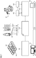
- FIG 1 Various components of a control system or a machine tool according to the improved concept are shown schematically in the context of different steps of a method according to the improved concept.
- FIG 2 different aspects of the process are shown.
- the control system has an electronic computing device CS, for example a CAM system, and a further electronic computing device NS, for example an NC, CNC or robot controller.
- the machine tool has the control system and a machine M, which is designed, for example, as an industrial robot or a classic machine tool in the narrower sense.
- target specifications for a workpiece WS in particular geometric ones, can be used Target specifications, as well as geometric dimensions and properties of a tool WZ, a tool path WP for machining the workpiece WS with the machine M are planned.
- the tool path WP comprises spatial information about how the tool WZ and / or the workpiece WS are to be guided through the machine M in order to achieve the target specifications for the workpiece WS.
- the tool path or tool trajectory WP can in particular be represented by discrete points, circular arcs and / or splines with the associated feed speed and machine parameters, it being possible to assign a section A1, A2, ... AN to one or more of the discrete points.
- Arithmetic operations which are carried out by the arithmetic unit CS are carried out offline, that is to say before the workpiece M is machined by the machine M.
- Arithmetic operations which are carried out by the further arithmetic unit NS are carried out online, that is to say during or parallel to the machining of the workpiece WS by the machine M.
- interaction data ID are determined offline in a step 100, for example by means of the computing device CS.
- the interaction data ID describe a geometric, in particular purely geometric, interaction of the tool WZ with the workpiece WS during one or more of the sections A1 to AN.
- Step 100 can be part of a path planning by the CAM system CS, for example.
- the tool WZ in particular a cutting edge S1 of the tool WZ, as in the left part of the figure FIG 2 shown, represented in a suitable mathematical manner, for example by means of a point cloud.
- This means that a geometry of the cutting edge S1 is represented by individual points.
- optional additional cutting edges S2, S3, S4 left in FIG 2 Not shown).
- the workpiece WS is also represented by a suitable mathematical representation.
- the workpiece WS is divided into a large number of geometric subunits or elements and thus approximately represented.
- the elements of a workpiece can be, for example, hexahedra, cubes, cuboids or various, even irregular, geometric bodies.
- the workpiece WS can be represented by a voxel model, in which it is represented by a uniform, regular covering or a covering with a grid of hexahedra, cuboids or cubes adapted to the workpiece geometry.
- the workpiece WS can be represented, for example, as a Dexel model.
- Other prior art models are also possible.
- the tool WZ is cut with the workpiece WS.
- the models for the tool WZ and the workpiece WS are subjected to Boolean operations. For example, such geometric sub-elements of the workpiece WS are identified and, to a certain extent, removed, which are touched or cut by points of the tool WZ.
- the interaction data ID can then, for example, in the form of intervention histograms, as in the middle part of FIG 2 shown, displayed and saved.
- an azimuthal angle of the tool WZ ie an angle which describes a position on a circumference of the tool WZ
- the vertical axis is, for example, a longitudinal position along a suitably parameterized longitudinal path L of the tool WZ, as in the left part of FIG 2 shown, plotted.
- the engagement histogram plots, for example, from 0 to 360 degrees and the cutting depths or contact surfaces over the longitudinal position of the cutting edges S1, S2, S3, S4.
- the coordinates of the cutting edges S1 to S4 thus defined are represented by lines which are designated by the reference symbols of the cutting edges S1 to S4.
- An exemplary point P on the cutting edge S1 of the tool WZ is in the left part of the FIG 2 and its coordinates, as described, are shown in the engagement histogram.
- An engagement area E is in the left part of the FIG 2 shown hatched.
- the engagement area E corresponds to an area on a surface, in particular a fictitious surface of the tool WZ, on which the tool WZ would theoretically touch the workpiece WS during the section of the tool path if the entire surface of the tool WZ would represent a cutting edge (lateral surface).
- an intervention only takes place where the area E meets the cutting edge S1, or a further cutting edge S2, S3, S4.
- the engagement area E is also in the engagement histogram in the middle of the FIG 2 shown, here simplified as a rectangular area.
- the area E overlaps with the cutting edge S1 and with the cutting edge S4 in the relevant section of the tool path WP considered.
- the geometric interaction of the tool WZ with the workpiece WS can be displayed and saved during the section of the tool path WP.
- intervention diagrams corresponding to several, in particular all of the sections A1, A2 ... AN of the tool path WP are generated created and saved as in the right part of the FIG 2 indicated.
- the interaction data ID are therefore available, for example, on the basis of the intervention histograms along the tool path WP.
- the interaction data ID are assigned to spatial and non-temporal positions of the tool WZ, they do not depend on configuration parameters such as, for example, a feed rate during the actual machining of the workpiece WS.
- the feed rate can therefore be changed at any time.
- interaction data ID can be generated during step 100 not only for a combination of a tool WZ and a workpiece WS, but corresponding interaction data for a large number of different combinations of different tools and workpieces.
- the determined and stored interaction data ID are used to determine a relationship between a force to be expected during the machining, which in particular acts on the tool WZ, and at least one configuration parameter of the machining.
- discretized chip thicknesses can be determined for the corresponding section.
- the configuration parameter can be a feed rate, for example.
- the relationship between the force to be expected and the feed rate is determined in such a way that an expression is obtained in which the force is parametrically dependent on the feed rate, for example only on the feed rate.
- the relationship of other or further configuration parameters in addition to or instead of the feed rate depend parametrically, for example a tool speed.
- the determination of the relationship can also include the determination of further process force parameters, which also contain the feed rate and / or the tool speed and / or further configuration parameters in parameter form.
- the determined relationship and / or the interaction data ID are transferred to the further computing device NS in a step 200 of the method, in particular in the form of a standardized format for machine code such as G-code.
- the further electronic computing device in particular NC control, NS, for example, generates one or more control commands in a step 300 of the method and transmits these, for example, to the machine M for machining the workpiece WZ in a step 400 of the method.
- the further computing device NS calculates the force online in step 200 based on the previously determined relationship of the force to be expected with the configuration parameter, for example the feed rate, during the machining of the workpiece WS.
- the further computing device NS adapts the machining, in particular the control commands, in order to optimize the machining of the workpiece WS.
- the adaptation of the machining can include an adaptation of the tool path WP in order to compensate for a deviation from a desired nominal dimension of the workpiece WS despite any possibly occurring high forces.
- the further computing device NS can use one or more stiffness values of the machine M for the compensation.
- the lower the rigidity of the machine M the greater the likelihood of such deviations and the more important it is to compensate them in order to be able to achieve a sufficiently high workpiece quality.
- Various embodiments of the method have an optional step 500, in which sensor data from sensors (not shown) attached to the machine M, for example, are recorded and transmitted to the further computing device NS.
- the further computing device NS can, for example, adapt the processing even more precisely and / or modify the relationship between the force to be expected and the at least one configuration parameter, so that greater accuracy is achieved.
- the sensors can include position or orientation sensors, which detect a deviation of an actual tool path of the tool WZ from a desired tool path, which takes into account, for example, the force calculated according to the relationship.
- the sensors can detect electrical quantities of a drive of the machine M, for example currents, in particular motor currents and / or spindle currents of a drive of the machine M, and based on these adapt the machining or adapt the relationship between the force to be expected and the configuration parameters.
- electrical quantities of a drive of the machine M for example currents, in particular motor currents and / or spindle currents of a drive of the machine M, and based on these adapt the machining or adapt the relationship between the force to be expected and the configuration parameters.
- mathematical methods for calculating the force can be based at least in part on empirical formulas and process force parameters, which are described, for example, in Altintas 2000 or Engin 2001.
- both the interaction data ID and the relationship between the force to be expected and the at least one configuration parameter were determined offline by means of the computing device CS so that only the at least one configuration parameter, in particular the feed rate, remains as a parameter in the relationship.
- the force was calculated online based on the relationship and the current value of the configuration parameter by means of the further computing device NS.
- This division offers increased flexibility compared to known approaches, since the at least one configuration parameter can be defined or changed shortly before processing or also during processing, and the interaction data ID or the relationship between force and configuration parameters still apply the forces that occur modeled. This also minimizes the amount of computation required during machining, since the relationship between force and feed rate or other configuration parameters already exists during machining and only concrete values of the parameters or factors need to be taken into account.
- At least parts of the determination of the relationship between the force to be expected and the configuration parameters are also carried out online using the further computing device NS.
- the interaction data ID is determined offline and all further procedural steps take place online. This division offers maximum flexibility when machining, since only purely geometrical information about the tool WZ and the workpiece WS is defined before machining. On the other hand, this increases the computing effort during processing.
- intermediate steps for determining the relationship can therefore be carried out offline, in particular for each of the sections A1 to AN, and stored along the tool path WP or transferred to the further computing device NS. In this way it is possible, depending on the available resources, priorities or other circumstances during production, to weigh the required online computing effort against the required flexibility in processing.
- an exact geometry of the tool WZ for determining the interaction data ID can be provided in encrypted form, for example to prevent inadmissible outflow of information to third parties. The same applies to other sensitive data.
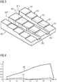
- FIG 3 A workpiece WS is shown schematically and by way of example, which is optimized with a conventional CNC milling method and with a method optimized according to a method based on the improved concept.
- the workpiece WS is designed as a stepped workpiece, so it has a plurality of areas B1, B2, B3, B4, B5, which have different but constant heights.
- the workpiece WS has a rectangular basic shape, for example.
- the specific shape of the workpiece WS is used only for explanation and is to be understood solely as an example that is in no way restrictive.
- a goal of the processing in the present example is a straight cut through the workpiece WS, the various areas B1 to B5 being cut through.
- a first cut SN1 was carried out according to a method which was optimized by means of a method according to the improved concept. In particular, reference is made to the statements in this regard FIG 1 and FIG 2 referred.
- the force on the tool WZ was repeatedly calculated in the manner described and the machining was adapted in such a way that the tool path was adapted to deviate from a desired tool path, that is to say the straight cut compensate.
- the resulting actual tool path WP1 corresponds to a straight line in a very good approximation.
- an associated deviation E1 of the actual tool path WP1 from the straight cut is plotted.
- the size of the error E1 moves over the entire first cut SN1 in a range that is significantly smaller than 0.2 mm.
- FIG 3 Another section SN2 is shown, which was carried out by means of a conventional milling process. Due to the different heights of the areas B1 to B5, a force acting on the tool WZ changes along the section SN2, that is to say along the corresponding tool path WP2. The consequence of this is that, for example, perpendicular to the cutting axis, a deviation from the straight cut occurs, which is greater, for example, the greater the height of the respective area B1 to B5. Since a machine tool always has a finite stiffness and due to a lack of compensation, this has deviations of the second tool path WP2, which are greater, for example, the greater the height of the respective area B1 to B5.
- the resulting cut SN2 deviates significantly more from the desired tool path than the first cut SN1.
- a second error E2 is plotted, which, analogous to error E1, represents a deviation, for example in mm, of the actual tool path WP2 from the straight cut along the cutting axis.
- the error E2 increases continuously along the tool path WP2 and reaches a maximum value of approximately 1.2 mm.
- the manufacturing quality of a numerically controlled machining of a workpiece can be improved according to the improved concept, with a higher flexibility of the machining being given.
- the optimization described represents a closed control loop, which contains a prediction of the physical behavior of the tool or workpiece or machine tool by means of models and can therefore anticipate possible deviations.
- the machining can be adjusted with high accuracy without requiring very high computing requirements during machining of the workpiece.
- Manual corrections for example by adapting a machine code after a component has been manufactured, can be dispensed with.
- various parameters can be defined shortly before the machining process, for example a position of the workpiece or a choice of the machine or a feed rate.
- parameters can even be determined during the process, for example specific material-dependent process force parameters, so that time-consuming calibration processes with corresponding test cuts can be omitted.
- Different embodiments use a comparison before processing simulated process forces, motor torques and spindle torques with motor and spindle torques measured during the machining of the workpiece.
- offline calculations described can be carried out on CAM systems.
- offline calculations using a cloud platform, on hardware close to the NC / RC controller or directly on an NC / RC controller are conceivable.
Abstract
Um Bearbeitungskonfigurationen flexibler berücksichtigen zu können, beinhaltet ein Verfahren zum Optimieren einer numerisch gesteuerten Bearbeitung eines Werkstücks (WS) ein Ermitteln von geometrischen Interaktionsdaten (ID). Ein Zusammenhang zwischen einer zu erwartenden Kraft und einem Konfigurationsparameter der Bearbeitung wird basierend auf den Interaktionsdaten (ID) bestimmt. Die Kraft wird während der Bearbeitung berechnet basierend auf dem Zusammenhang und einem aktuellen Wert des wenigstens einen Konfigurationsparameters. Die Bearbeitung wird abhängig von der berechneten Kraft angepasst.In order to be able to take machining configurations into account more flexibly, a method for optimizing a numerically controlled machining of a workpiece (WS) includes determining geometric interaction data (ID). A relationship between an expected force and a configuration parameter of the machining is determined based on the interaction data (ID). The force is calculated during processing based on the relationship and a current value of the at least one configuration parameter. The machining is adjusted depending on the calculated force.
Description
Die Erfindung betrifft ein Verfahren zum rechnergestützten Optimieren einer numerisch gesteuerten Bearbeitung eines Werkstücks durch ein Werkzeug, wobei Interaktionsdaten ermittelt werden, welche eine geometrische Interaktion des Werkzeugs mit dem Werkstück in einem Abschnitt einer Werkzeugbahn beschreiben, sowie ein Computerprogramm zur Durchführung eines solchen Verfahrens. Ferner betrifft die Erfindung ein Steuerungssystem zur numerisch gesteuerten Bearbeitung eines Werkstücks durch ein Werkzeug und zur rechnergestützten Optimierung der Bearbeitung, welches eine elektronische Recheneinrichtung zur Ermittlung von Interaktionsdaten und eine weitere elektronische Recheneinrichtung aufweist, sowie eine Werkzeugmaschine mit einem solchen Steuerungssystem.The invention relates to a method for computer-aided optimization of a numerically controlled machining of a workpiece by a tool, interaction data being determined which describe a geometric interaction of the tool with the workpiece in a section of a tool path, and a computer program for carrying out such a method. Furthermore, the invention relates to a control system for numerically controlled machining of a workpiece by a tool and for computer-aided optimization of the machining, which has an electronic computing device for determining interaction data and a further electronic computing device, and a machine tool with such a control system.
Das Dokument
Das Dokument
Bekannte Optimierungsverfahren erfordern mitunter einen sehr hohen Rechenaufwand, sodass entsprechende Berechnungen oder Simulationen nur vor der eigentlichen Bearbeitung des Werkstücks, also offline, durchgeführt werden können. Dies führt unter anderem dazu, dass die genauen Konfigurationen, wie zum Beispiel Maschinenauswahl, Werkzeugauswahl, Einspannbedingungen des Werkstücks oder Materialparameter, vorab definiert werden müssen. Das entsprechende Bearbeitungsprogramm ist daher nur für genau eine Konfiguration optimiert, was zu einer erheblichen Einschränkung der Flexibilität des Bearbeitungsprozesses führt. Andererseits ist es aufgrund des hohen Rechenaufwands nicht möglich, Simulationen vollständig online, also während der Bearbeitung des Werkstücks, durchzuführen.Known optimization methods sometimes require a very high amount of computation, so that corresponding calculations or simulations can only be carried out before the actual machining of the workpiece, that is to say offline. Among other things, this means that the exact configurations, such as machine selection, tool selection, clamping conditions of the workpiece or material parameters, must be defined in advance. The corresponding machining program is therefore only optimized for one configuration, which leads to a considerable restriction of the flexibility of the machining process. On the other hand, due to the high computing effort, it is not possible to carry out simulations completely online, i.e. while the workpiece is being machined.
Vor diesem Hintergrund ist es eine Aufgabe der vorliegenden Erfindung, ein verbessertes Konzept zum rechnergestützten Optimieren einer numerisch gesteuerten Bearbeitung eines Werkstücks durch ein Werkzeug anzugeben, welches eine flexiblere Berücksichtigung unterschiedlicher Konfigurationen bei der Bearbeitung ermöglicht.Against this background, it is an object of the present invention to provide an improved concept for the computer-aided optimization of a numerically controlled machining of a workpiece by a tool, which enables a more flexible consideration of different configurations during machining.
Diese Aufgabe wird erfindungsgemäß durch ein Verfahren, ein Computerprogramm, ein Steuerungssystem sowie eine Werkzeugmaschine gemäß der unabhängigen Ansprüche gelöst. Vorteilhafte Ausführungsformen und Weiterbildungen sind Gegenstand der abhängigen Ansprüche.This object is achieved according to the invention by a method, a computer program, a control system and a machine tool according to the independent claims. Advantageous embodiments and further developments are the subject of the dependent claims.
Das verbesserte Konzept beruht auf der Idee, eine Berechnung während der Bearbeitung des Werkstücks auftretender Kräfte, welche zur Anpassung der Bearbeitung herangezogen werden können, zum Teil offline, das bedeutet vor der eigentlichen Bearbeitung des Werkstücks durch eine Werkzeugmaschine, und zum Teil online, das bedeutet während der beziehungsweise parallel zur Bearbeitung des Werkstücks durch das Werkzeug. Dabei werden rein geometrische Interaktionen zwischen Werkzeug und Werkstück, welche also unabhängig oder entkoppelt von Konfigurationsparametern der Bearbeitung wie zum Beispiel der Vorschubgeschwindigkeit sind, offline durchgeführt und für die Onlinebearbeitung des Werkstücks bereitgestellt. Ein Zusammenhang zwischen den geometrischen Interaktionen und einer zu erwartenden Kraft kann dann online, offline oder teilweise online und teilweise offline durchgeführt werden. Eine tatsächliche Berechnung der Kraft basierend auf dem Zusammenhang und einem Konfigurationsparameter sowie eine Anpassung der Bearbeitung erfolgen online.The improved concept is based on the idea of calculating forces occurring during the machining of the workpiece, which can be used to adapt the machining, partly offline, which means before the actual machining of the workpiece by a machine tool, and partly online, which means during or parallel to the machining of the workpiece by the tool. Thereby purely geometrical interactions between tool and Workpieces that are independent or decoupled from configuration parameters of the machining, such as the feed rate, are carried out offline and made available for the online machining of the workpiece. A connection between the geometric interactions and an expected force can then be carried out online, offline or partly online and partly offline. An actual calculation of the force based on the context and a configuration parameter as well as an adaptation of the processing are done online.
Gemäß einem unabhängigen Aspekt des verbesserten Konzepts wird ein Verfahren zum, insbesondere rechnergestützten, Optimieren einer numerisch gesteuerten Bearbeitung eines Werkstücks durch ein Werkzeug angegeben. Das Verfahren beinhaltet ein Ermitteln von Interaktionsdaten, welche eine geometrische Interaktion des Werkzeugs mit dem Werkstück in einem Abschnitt einer Werkzeugbahn beschreiben, vor der Bearbeitung. Ein Zusammenhang zwischen einer während der Bearbeitung zu erwartenden Kraft, insbesondere während des genannten Abschnitts der genannten Werkzeugbahn zu erwarteten Kraft, und wenigstens einem Konfigurationsparameter der Bearbeitung wird basierend auf den Interaktionsdaten bestimmt. Die Kraft wird während der Bearbeitung berechnet basierend auf dem Zusammenhang und einem aktuellen Wert des wenigstens einen Konfigurationsparameters während der Bearbeitung. Die Bearbeitung wird abhängig von der berechneten Kraft angepasst.According to an independent aspect of the improved concept, a method for, in particular computer-aided, optimization of a numerically controlled machining of a workpiece by a tool is specified. The method includes determining interaction data, which describe a geometric interaction of the tool with the workpiece in a section of a tool path, before machining. A relationship between a force to be expected during the machining, in particular a force to be expected during the said section of the said tool path, and at least one configuration parameter of the machining is determined based on the interaction data. The force is calculated during processing based on the relationship and a current value of the at least one configuration parameter during processing. The machining is adjusted depending on the calculated force.
Unter "rechnergestützt" kann hier und im Folgenden verstanden werden, dass eine Implementierung des Verfahrens derart gestaltet ist, dass wenigstens ein Verfahrensschritt mittels einer elektronischen Recheneinheit, insbesondere mittels eines Mikroprozessors oder eines integrierten Rechnersystems ausgeführt wird.Here and below, “computer-aided” can be understood to mean that an implementation of the method is designed in such a way that at least one method step is carried out by means of an electronic computing unit, in particular by means of a microprocessor or an integrated computer system.
Die Werkzeugbahn, auch einfach Bahn, Pfad oder Werkzeugpfad genannt, beschreibt einen räumlichen Verlauf, insbesondere gewünschten Verlauf oder Sollverlauf, des Werkzeugs während der Bearbeitung, insbesondere einer Position und/oder Orientierung des Werkzeugs. Die Werkzeugbahn liegt insbesondere in diskreter Form vor. Der Abschnitt der Werkzeugbahn entspricht beispielsweise einem Bereich um einen diskreten Punkt der Werkzeugbahn herum. Alternativ kann der Abschnitt einem Bereich zwischen zwei benachbarten oder nicht benachbarten diskreten Punkten der Werkzeugbahn oder um mehrere diskrete Punkte der Werkzeugbahn herum entsprechen. Insbesondere handelt es sich bei dem Abschnitt um einen räumlichen Abschnitt, nicht etwa einen zeitlichen Abschnitt, sodass der Abschnitt die geometrische Interaktion des Werkzeugs mit dem Werkstück unabhängig von Konfigurationsparametern ist, wie zum Beispiel einer Vorschubgeschwindigkeit, oder einer Werkzeugdrehzahl während der tatsächlichen Bearbeitung.The tool path, also simply called path, path or tool path, describes a spatial course, in particular the desired course or target course, of the tool during the processing, in particular a position and / or orientation of the tool. The tool path is in particular in a discrete form. The section of the tool path corresponds, for example, to an area around a discrete point on the tool path. Alternatively, the section may correspond to a region between two adjacent or non-adjacent discrete points on the tool path or around several discrete points on the tool path. In particular, the section is a spatial section, not a temporal section, so that the section's geometric interaction of the tool with the workpiece is independent of configuration parameters, such as, for example, a feed rate or a tool speed during the actual machining.
Bei der geometrischen Interaktion des Werkzeugs mit dem Werkstück handelt es sich insbesondere um eine geometrische Interaktion einer oder mehrerer Schneiden des Werkzeugs mit dem Werkstück.The geometric interaction of the tool with the workpiece is in particular a geometric interaction of one or more cutting edges of the tool with the workpiece.
Die geometrische Interaktion beinhaltet Informationen darüber, ob eine oder mehrere Schneiden des Werkzeugs in dem Abschnitt das Werkstück berühren, wenn ja welche der Schneiden und an welchem Punkt der Schneiden. Dabei kann ein Punkt einer Schneide beispielsweise durch eine Längskoordinate oder einen Längsparameter entlang einer Längsachse des Werkstücks und einer Azimutal- oder Winkelkoordinate oder einem Azimutal- oder Winkelparameter entlang eines Umfangs des Werkzeugs, insbesondere in einer Ebene senkrecht zur Längsachse des Werkzeugs charakterisiert sein. Die Längsachse des Werkzeugs entspricht beispielsweise einer Rotationsachse des Werkzeugs, insbesondere wenn das Werkzeug während der Bearbeitung um die Rotationsachse rotiert, wie beispielsweise bei einem Fräswerkzeug.The geometric interaction includes information about whether one or more cutting edges of the tool in the section touch the workpiece, if so which of the cutting edges and at which point the cutting edges. A point of a cutting edge can be characterized, for example, by a longitudinal coordinate or a longitudinal parameter along a longitudinal axis of the workpiece and an azimuthal or angular coordinate or an azimuthal or angular parameter along a circumference of the tool, in particular in a plane perpendicular to the longitudinal axis of the tool. The longitudinal axis of the tool corresponds, for example, to an axis of rotation of the tool, in particular if the tool rotates about the axis of rotation during machining, such as, for example, in the case of a milling tool.
Bei der Bearbeitung des Werkstücks handelt es sich insbesondere um eine spanabhebende Bearbeitung, beispielsweise handelt es sich um eine spanabhebende Bearbeitung mit einem rotierenden Werkzeug und/oder eines rotierenden Werkstücks. Beispielsweise kann es sich um eine Fräsbearbeitung, eine Drehbearbeitung, eine Bohrbearbeitung oder eine Schleifbearbeitung handeln.The machining of the workpiece is in particular machining, for example machining with a rotating one Tool and / or a rotating workpiece. For example, it can be milling, turning, drilling or grinding.
Bei der zu erwartenden Kraft handelt es sich beispielsweise um eine während der Bearbeitung auf das Werkzeug und somit auf eine Werkzeugmaschine wirkende Kraft, welche aus der Interaktion des Werkzeugs mit dem Werkstück resultiert, beziehungsweise gleichbedeutend um eine Kraft welche während der Bearbeitung auf das Werkstück wirkt.The force to be expected is, for example, a force acting on the tool and thus on a machine tool during machining, which results from the interaction of the tool with the workpiece, or equivalent to a force which acts on the workpiece during machining.
Bei dem Zusammenhang zwischen der zu erwartenden Kraft und dem wenigstens einen Konfigurationsparameter der Bearbeitung handelt es sich insbesondere um einen mathematischen Zusammenhang, beispielsweise um einen expliziten mathematischen Zusammenhang, sodass die Kraft als Funktion des wenigstens einen Konfigurationsparameters angegeben wird, oder um einen impliziten Zusammenhang, sodass eine Funktion der Kraft gleich einer Funktion des wenigstens einen Konfigurationsparameters ist. Der Zusammenhang zwischen der zu erwartenden Kraft und dem mindestens einen Konfigurationsparameter kann vollständig offline oder teilweise offline und teilweise online erfolgen.The relationship between the force to be expected and the at least one configuration parameter of the processing is in particular a mathematical relationship, for example an explicit mathematical relationship, so that the force is specified as a function of the at least one configuration parameter, or an implicit relationship, such that a function of the force is equal to a function of the at least one configuration parameter. The relationship between the force to be expected and the at least one configuration parameter can be completely offline or partly offline and partly online.
Hier und im Folgenden bedeutet "offline", dass der entsprechende Schritt nicht während einer tatsächlichen Bearbeitung des Werkstücks durch das Werkzeug erfolgt, sondern insbesondere vor der tatsächlichen Bearbeitung. Entsprechend bedeutet "online" hier und im Folgenden, dass der entsprechende Schritt während der oder parallel zur tatsächlichen Bearbeitung des Werkstücks erfolgt.Here and in the following "offline" means that the corresponding step is not carried out during an actual machining of the workpiece by the tool, but in particular before the actual machining. Accordingly, “online” here and below means that the corresponding step takes place during or parallel to the actual machining of the workpiece.
Da die Berechnung der Kraft basierend auf dem bestimmten Zusammenhang und einem aktuellen Wert des wenigstens einen Konfigurationsparameters während der Bearbeitung erfolgt, findet diese Berechnung "online" statt, ebenso wie das Anpassen der Bearbeitung abhängig von der berechneten Kraft.Since the calculation of the force is based on the determined relationship and a current value of the at least one configuration parameter during the processing, this calculation takes place “online”, as does the adaptation of the processing depending on the calculated force.
Bei dem aktuellen Wert des wenigstens einen Konfigurationsparameters handelt es sich um einen Wert des wenigstens einen Konfigurationsparameters zu einem Zeitpunkt, zu dem sich das Werkzeug während der tatsächlichen Bearbeitung in dem genannten Abschnitt befindet. Je nachdem welche Parameter der wenigstens eine Konfigurationsparameter umfasst, können einer oder mehrere Parameter des wenigstens einen Konfigurationsparameters während eines Teils oder der gesamten Bearbeitung des Werkstücks beziehungsweise während des Abfahrens der Werkzeugbahn konstant sein oder er kann sich während der Bearbeitung verändern, beispielsweise dynamisch.The current value of the at least one configuration parameter is a value of the at least one configuration parameter at a point in time at which the tool is in said section during the actual machining. Depending on which parameter the at least one configuration parameter comprises, one or more parameters of the at least one configuration parameter can be constant during part or the entire machining of the workpiece or during the movement of the tool path, or it can change, for example dynamically, during machining.
Durch das Anpassen der Bearbeitung abhängig von der berechneten Kraft wird die Bearbeitung des Werkstücks optimiert. Mit Vorteil kann dadurch eine Qualitätsverbesserung bei der Herstellung des Werkstücks erzielt werden, da durch die Anpassung der Bearbeitung Einflüsse während der Bearbeitung auftretender Kräfte, die während einer Planung der Werkzeugbahn nicht berücksichtigt werden können oder aufgrund des hohen numerischen Rechenaufwands nicht berücksichtigt wurden, nachträglich online berücksichtigt werden. Dies kann insbesondere vorteilhaft sein, wenn bei der Bearbeitung hohe Kräfte auftreten, beispielsweise bei schwer zerspanbaren Materialien, was eine elastische Verformung der Werkzeugmaschine und beispielsweise eine signifikante Abweichung einer tatsächlichen von der geplanten Werkzeugbahn zur Folge haben kann. Die Abweichung von der gewünschten Werkzeugbahn kann jedoch wiederum eine Abweichung finaler Werkstückmaße von Sollmaßen führen, beispielsweise zu einer Verletzung von Form-, Maß- und/oder Lagetoleranzen, was mit einer reduzierten Produktqualität einhergeht.By adapting the machining depending on the calculated force, the machining of the workpiece is optimized. This can advantageously result in a quality improvement in the production of the workpiece, since by adapting the machining, influences occurring during machining, which cannot be taken into account during planning of the tool path or were not taken into account due to the high numerical computational effort, are subsequently taken into account online become. This can be particularly advantageous if high forces occur during machining, for example in the case of materials that are difficult to machine, which can result in elastic deformation of the machine tool and, for example, a significant deviation of an actual from the planned tool path. However, the deviation from the desired tool path can in turn lead to a deviation of the final workpiece dimensions from the nominal dimensions, for example to a violation of shape, dimension and / or position tolerances, which is associated with a reduced product quality.
Besonders vorteilhaft ist gemäß dem Verfahren nach dem verbesserten Konzept, dass die Anpassung online während der Bearbeitung erfolgt, und damit auch eine Qualität des aktuell bearbeiteten Werkstücks verbessert werden kann, nicht nur eine Qualität von nachfolgend zu bearbeitenden Werkstücken im Rahmen eines iterativen Vorgehens. Damit kann ein Werkstückausschuss reduziert werden.It is particularly advantageous according to the method according to the improved concept that the adaptation takes place online during processing, and thus a quality of the workpiece currently being processed can be improved, not just a quality of workpieces to be subsequently machined in the An iterative approach. A workpiece scrap can thus be reduced.
Ein weiterer Vorteil ergibt sich daraus, dass die Berechnung der Kräfte basierend auf dem Zusammenhang und einem aktuellen Wert des wenigstens einen Konfigurationsparameters ebenfalls online während der Bearbeitung erfolgt. Dies hat zur Folge, dass ein konkreter Wert des Konfigurationsparameters auch unmittelbar vor der Bearbeitung festgelegt werden kann, insbesondere zu einem Zeitpunkt, zu dem die geometrischen Interaktionsdaten bereits bestimmt wurden. Ebenso kann der Konfigurationsparameter online während der Bearbeitung verändert werden. Dies führt zu einer deutlichen Erhöhung der Flexibilität der Bearbeitung.Another advantage results from the fact that the calculation of the forces based on the relationship and a current value of the at least one configuration parameter is also carried out online during the processing. The consequence of this is that a specific value of the configuration parameter can also be determined immediately before the processing, in particular at a point in time at which the geometric interaction data have already been determined. The configuration parameter can also be changed online during processing. This leads to a significant increase in the flexibility of processing.
Dadurch, dass die Interaktionsdaten dem Abschnitt zugeordnet sind, welcher ein räumlicher, nicht ein zeitlicher Abschnitt ist, können Konfigurationsparameter wie beispielsweise eine Vorschubgeschwindigkeit, eine Werkzeug- oder Werkstückdrehzahl, online während der Bearbeitung verändert werden.Because the interaction data are assigned to the section which is a spatial, not a temporal section, configuration parameters such as a feed rate, a tool or workpiece speed can be changed online during the machining.
Dadurch, dass wesentliche Teile der Optimierung, insbesondere das Berechnen der Kraft online erfolgt, ist es vorteilhafterweise nicht erforderlich, sehr große Datenmengen vorzuhalten, wie dies beispielsweise bei einer vollständig offline erfolgenden Optimierung der Fall wäre.As a result of the fact that essential parts of the optimization, in particular the calculation of the force, are carried out online, it is advantageously not necessary to keep very large amounts of data available, as would be the case, for example, with a completely offline optimization.
Ferner ist eine Unterstützung der Bearbeitung beziehungsweise der Optimierung gemäß dem verbesserten Konzept durch eine Sensorüberwachung während der Bearbeitung zwar möglich, jedoch nicht in derart aufwändiger und detaillierter Form erforderlich, wie es beispielsweise bei einer vollständig online erfolgenden Optimierungsmethode wäre.Furthermore, processing or optimization according to the improved concept can be supported by sensor monitoring during processing, but not in such a complex and detailed form as would be the case, for example, with a fully online optimization method.
Gemäß wenigstens einer Ausgestaltung des Verfahrens werden die Interaktionsdaten ermittelt und danach gespeichert, um während der Bearbeitung zur Verfügung zu stehen.According to at least one embodiment of the method, the interaction data are determined and then stored in order to be available during processing.
Gemäß wenigstens einer Ausgestaltung werden die Verfahrensschritte des Ermittelns von Interaktionsdaten, des Bestimmens des Zusammenhangs, des Berechnens der Kraft sowie des Anpassens der Bearbeitung für weitere Abschnitte der Werkzeugbahn durchgeführt, beispielsweise für alle Abschnitte also für die gesamte Werkzeugbahn.According to at least one embodiment, the method steps of determining interaction data, determining the relationship, calculating the force and adapting the machining are carried out for further sections of the tool path, for example for all sections, that is to say for the entire tool path.
Gemäß zumindest einer Ausgestaltung beinhaltet das Verfahren einen Schritt zur Bahnplanung währenddessen die Werkzeugbahn ermittelt wird. Die Interaktionsdaten werden beispielsweise während der Bahnplanung ermittelt.According to at least one embodiment, the method includes a step for path planning during which the tool path is determined. The interaction data are determined, for example, during path planning.
Gemäß wenigstens einer Ausgestaltung des Verfahrens umfasst der wenigstens eine Konfigurationsparameter eine Vorschubgeschwindigkeit des Werkstücks oder des Werkzeugs, eine Drehzahl des Werkzeugs, eine Position des Werkzeugs oder des Werkstücks, wobei die Position insbesondere eine oder mehrere kartesische Positionen und/oder eine oder mehrere Orientierungen oder Winkelpositionen beinhalten kann.According to at least one embodiment of the method, the at least one configuration parameter comprises a feed speed of the workpiece or the tool, a rotational speed of the tool, a position of the tool or the workpiece, the position in particular one or more Cartesian positions and / or one or more orientations or angular positions can include.
Gemäß wenigstens einer Ausgestaltung umfasst der wenigstens eine Konfigurationsparameter eine oder mehrere Materialeigenschaften des Werkstücks oder des Werkzeugs.According to at least one embodiment, the at least one configuration parameter comprises one or more material properties of the workpiece or the tool.
Gemäß wenigstens einer Ausgestaltung umfasst das Anpassen der Bearbeitung eine Korrektur oder teilweise Korrektur der Werkzeugbahn und/oder eine Anpassung eines oder mehrerer des wenigstens einen Konfigurationsparameters.According to at least one embodiment, the adaptation of the machining comprises a correction or partial correction of the tool path and / or an adaptation of one or more of the at least one configuration parameter.
Gemäß wenigstens einer Ausführungsform werden das Werkzeug sowie das Werkstück zur Bestimmung der Interaktionsdaten jeweils durch geeignete mathemaische Modelle dargestellt.In accordance with at least one embodiment, the tool and the workpiece for determining the interaction data are each represented by suitable mathematical models.
Gemäß zumindest einer Ausführungsform wird das Werkzeug zur Bestimmung der Interaktionsdaten durch eine Punktewolke repräsentiert, das heißt eine Geometrie der einen oder mehreren Schneiden wird durch einzelne, diskrete Punkte dargestellt.According to at least one embodiment, the tool for determining the interaction data is represented by a point cloud, that is to say a geometry of the one or more cutting edges is represented by individual, discrete points.
Gemäß wenigstens einer Ausführungsform wird das Werkstück zur Bestimmung der Interaktionsdaten mittels eines Voxel-Modells repräsentiert, also mittels einer gleichmäßigen und regulären oder an die veränderliche Werkstückgeometrie angepasste Überdeckung mit einem Gitter aus Hexaedern oder Quadern beziehungsweise Würfeln.According to at least one embodiment, the workpiece for determining the interaction data is represented by means of a voxel model, that is to say by means of a uniform and regular overlap with a grid of hexahedra or cuboids or cubes or adapted to the variable workpiece geometry.
Gemäß wenigstens einer Ausführungsform wird das Werkstück zur Bestimmung der Interaktionsdaten durch ein Dexel-Modell (Englisch: depth pixel) repräsentiert.According to at least one embodiment, the workpiece for determining the interaction data is represented by a Dexel model (English: depth pixel).
Sowohl bei dem Dexel-Modell als auch bei dem Voxel-Modell oder bei anderen geeigneten Modellen wird das Werkstück zur Bestimmung der Interaktionsdaten durch eine Vielzahl geometrischer Elemente dargestellt und angenähert.In the case of the Dexel model as well as the Voxel model or other suitable models, the workpiece for determining the interaction data is represented and approximated by a large number of geometric elements.
Gemäß wenigstens einer Ausführungsform umfasst das Ermitteln der Interaktionsdaten ein Verschneiden des simulierten Werkzeuges mit dem simulierten Werkstück. Das Verschneiden umfasst beispielsweise eine Boolesche Operation. Dabei werden beispielsweise Elemente des Werkstücks identifiziert, die von Punkten des modellierten Werkzeuges während des Abschnitts der Werkzeugbahn berührt oder geschnitten werden.According to at least one embodiment, the determination of the interaction data comprises an intersection of the simulated tool with the simulated workpiece. The blending includes, for example, a Boolean operation. For example, elements of the workpiece are identified that are touched or cut by points of the modeled tool during the section of the tool path.
Gemäß wenigstens einer Ausgestaltung des Verfahrens wird eine während der Bearbeitung zu erwartenden Spanungsdicke ermittelt und der Zusammenhang zwischen der zu erwartenden Kraft und dem wenigstens einen Konfigurationsparameter wird basierend auf der ermittelten Spanungsdicke bestimmt. Insbesondere handelt es sich bei der Spanungsdicke um eine Spanungsdicke während des Abschnitts.According to at least one embodiment of the method, a chip thickness to be expected during processing is determined and the relationship between the force to be expected and the at least one configuration parameter is determined based on the chip thickness determined. In particular, the chip thickness is a chip thickness during the section.
Bei der Spanungsdicke handelt es sich um eine Größe, welche einen großen Einfluss auf eine Schnittkraft während der Bearbeitung haben kann. Daher hat eine Berücksichtigung der Spanungsdicke eine erhöhte Genauigkeit der Bestimmung des Zusammenhangs beziehungsweise der Kraftberechnung zur Folge.The chip thickness is a size that can have a major influence on a cutting force during machining. Therefore, taking the chip thickness into account results in increased accuracy in determining the relationship or the force calculation.
Insbesondere kann das Ermitteln der Interaktionsdaten vollständig offline erfolgen. Das Ermitteln der Interaktionsdaten kann beispielsweise mittels eines Systems zur rechnerunterstützen Fertigung (Englisch: computer aided manufacturing, kurz CAM) erfolgen.In particular, the interaction data can be determined completely offline. The interaction data can be determined, for example, by means of a computer-aided manufacturing (CAM) system.
Dadurch kann mit Vorteil ein Rechenaufwand, welcher online nicht oder nur unter erhöhtem Aufwand zu leisten wäre, von der Bearbeitung des Werkstücks und der Berechnung der Kraft während der tatsächlichen Bearbeitung entkoppelt werden.As a result, a computational effort that could not be done online or only with increased effort can advantageously be decoupled from the machining of the workpiece and the calculation of the force during the actual machining.
Gemäß wenigstens einer Ausgestaltung erfolgt das Ermitteln der Interaktionsdaten wenigstens teilweise unter Verwendung eines Grafikprozessors (Englisch: graphic processing unit, kurz GPU), insbesondere einer GPU des CAM-Systems. Insbesondere werden Rechenschritte zum Ermitteln der Interaktionsdaten mittels der GPU durchgeführt.According to at least one embodiment, the interaction data is determined at least partially using a graphics processor (GPU), in particular a GPU of the CAM system. In particular, computing steps to determine the interaction data are carried out by means of the GPU.
Eine Verwendung von GPUs für technische Simulationen wird auch als GPGPU (Englisch: general purpose computation on graphics processing unit) bezeichnet. Ein Vorteil bei der Verwendung einer GPU für bestimmte oder alle Rechenschritte zum Ermitteln der Interaktionsdaten liegt darin, dass leistungsfähige GPUs aufgrund ihrer Konstruktion bei bestimmten Rechenoperationen besonders effizient arbeiten. Insbesondere für die parallele Ausführung gleichförmiger Aufgaben, wie sie auch bei der Ermittlung der Interaktionsdaten, sind GPUs, welche gegenüber CPUs diesbezügliche höhere Rechenleistungen und Speicherbandbreiten aufweisen können, besonders vorteilhaft. Insbesondere weisen typische CAM-Systeme ohnehin leistungsfähige GPUs auf, welche vorteilhafterweise hier auch zum Ermitteln der Interaktionsdaten zumindest teilweise herangezogen werden können.The use of GPUs for technical simulations is also referred to as GPGPU (General Purpose Computation on Graphics Processing Unit). An advantage of using a GPU for certain or all computing steps to determine the interaction data is that powerful GPUs work particularly efficiently due to their design in certain computing operations. GPUs, which can have higher computing power and memory bandwidths in this regard compared to CPUs, are particularly advantageous for the parallel execution of uniform tasks, as they also occur when determining the interaction data. In particular, typical CAM systems have powerful GPUs anyway, which can advantageously also be used here at least in part to determine the interaction data.
Dadurch kann eine besonders effiziente und parallele Berechnungsweise der Interaktionsdaten erfolgen. Dazu können beispielsweise bekannte Softwarebibliotheken eingesetzt werden.This enables the interaction data to be calculated in a particularly efficient and parallel manner. Known software libraries can be used for this purpose, for example.
Gemäß wenigstens einer Ausgestaltung erfolgt das Bestimmen des Zusammenhangs zwischen der zu erwartenden Kraft und dem wenigstens einen Konfigurationsparameter wenigstens teilweise vor Beginn der Bearbeitung, also wenigstens teilweise offline.According to at least one embodiment, the relationship between the force to be expected and the at least one configuration parameter is determined at least partially before the start of the processing, that is to say at least partially offline.
Je größer der Anteil der offline durchgeführten Rechenoperationen, desto geringer ist vorteilhafterweise der Rechenaufwand online. Andererseits, je größer ein Anteil online durchgeführter Operationen, desto größer ist die Flexibilität hinsichtlich der konkreten Konfiguration bei der Bearbeitung. Ein Verfahren nach dem verbesserten Konzept erlaubt vorteilhafterweise ein Abwägen der Vorteile.The greater the proportion of the computing operations carried out offline, the less advantageously the computing effort online. On the other hand, the greater the proportion of operations performed online, the greater the flexibility with regard to the specific configuration during processing. A method according to the improved concept advantageously allows the advantages to be weighed up.
Gemäß wenigstens einer Ausgestaltung umfasst das Anpassen der Bearbeitung eine Korrektur der Werkzeugbahn oder einer Werkzeugtrajektorie oder der Vorschubgeschwindigkeit oder einer Werkzeug- oder Werkstückdrehzahl.According to at least one embodiment, the adaptation of the machining comprises a correction of the tool path or a tool trajectory or the feed rate or a tool or workpiece speed.
Dadurch kann vorteilhafterweise eine Qualitätsverbesserung auch des aktuell bearbeiteten Werkstücks durch eine Onlinekompensation eventueller Abweichungen von der Werkzeugbahn erzielt werden.As a result, the quality of the workpiece currently being machined can also be improved by online compensation of any deviations from the tool path.
Gemäß wenigstens einer Ausgestaltung des Verfahrens beinhaltet dieses außerdem ein Erfassen von Sensordaten während der Bearbeitung und ein Anpassen des Zusammenhangs oder eines Modells zur Berechnung der Kraft abhängig von den erfassten Sensordaten.In accordance with at least one embodiment of the method, this also includes acquiring sensor data during processing and adapting the relationship or a model for calculating the force depending on the acquired sensor data.
Bei den Sensordaten kann es sich beispielsweise um Ausgabedaten von Sensoren handeln, welche an der Werkzeugmaschine, insbesondere außen an der Werkzeugmaschine, angebracht sind oder von Sensoren zur Erfassung interner elektrischer Größen der Werkzeugmaschine, beispielsweise eines Antriebs der Werkzeugmaschine. Die Sensordaten können beispielsweise einen Motorstrom oder Spindelstrom eines Antriebs der Werkzeugmaschine, Materialparameter des Werkstücks oder des Werkzeugs, Werkzeugpositionen oder -orientierungen, Werkstückpositionen oder -orientierungen oder Größen zur Abschätzung einer Abnutzung des Werkzeugs entsprechen.The sensor data can be, for example, output data from sensors which are attached to the machine tool, in particular on the outside of the machine tool, or from sensors for detecting internal electrical variables of the machine tool, for example a drive of the machine tool. The sensor data can be, for example, a motor current or spindle current of a drive of the machine tool, material parameters of the workpiece or the tool, Tool positions or orientations, workpiece positions or orientations or sizes to estimate wear of the tool.
Damit kann die Genauigkeit der Kräftebestimmung, insbesondere der Bestimmung des Zusammenhangs beziehungsweise der Berechnung der Kräfte weiter erhöht werden und damit eine weitere Qualitätsverbesserung der Bearbeitung erzielt werden.In this way, the accuracy of the determination of forces, in particular the determination of the relationship or the calculation of the forces, can be increased further and a further improvement in the quality of the machining can be achieved.
Gemäß wenigstens einer Ausgestaltung wird eine Abweichung einer Ist-Position des Werkzeugs während der Bearbeitung von einer Soll-Position gemäß der korrigierten Werkzeugbahn abhängig von den Sensordaten bestimmt. Das Anpassen des Zusammenhangs oder des Modells wird abhängig von der Abweichung von Ist-Position und Soll-Position durchgeführt.According to at least one embodiment, a deviation of an actual position of the tool during machining from a target position is determined according to the corrected tool path depending on the sensor data. The relationship or model is adjusted depending on the deviation of the actual position and the target position.
Dabei ist anzumerken, dass die korrigierte Werkzeugbahn unter Umständen identisch zur ursprünglichen Werkzeugbahn sein kann, beispielsweise wenn die berechneten Kräfte keine Notwendigkeit zur Anpassung der Werkzeugbahn ergeben haben.It should be noted that under certain circumstances the corrected tool path can be identical to the original tool path, for example if the calculated forces have shown no need to adjust the tool path.
Gemäß wenigstens einer Ausgestaltung erfolgt die Korrektur der Werkzeugbahn abhängig von einem oder mehreren Steifigkeitswerten der Werkzeugmaschine zur Durchführung der Bearbeitung.According to at least one embodiment, the tool path is corrected as a function of one or more stiffness values of the machine tool for carrying out the machining.
Je höher die statische oder frequenzabhängige Steifigkeit und Dämpfung der Werkzeugmaschine, desto geringer kann ein Einfluss der während der Bearbeitung auftretenden Kräfte sein und desto geringer kann eine zu erwartende Abweichung von der erwünschten Werkzeugbahn sein. Die Steifigkeitswerte können beispielsweise fest hinterlegt und abgerufen oder gemessen werden. Durch Berücksichtigung der Steifigkeitswerte ist eine genauere Anpassung der Bearbeitung beziehungsweise Korrektur der Werkzeugbahn möglich. Außerdem können durch die Berücksichtigung der Steifigkeitswerte auch Werkzeugmaschinen mit geringerer Steifigkeit eingesetzt werden.The higher the static or frequency-dependent stiffness and damping of the machine tool, the less an influence of the forces occurring during machining can be and the less an expected deviation from the desired tool path can be. The stiffness values can, for example, be stored and called up or measured. By taking the stiffness values into account, a more precise adaptation of the machining or correction of the tool path is possible. In addition, by considering the stiffness values, machine tools with lower stiffness can also be used.
Unter einer "Werkzeugmaschine" wird hier und im Folgenden eine Maschine zur Fertigung von Werkstücken mit Werkzeugen verstanden. Darunter fallen insbesondere konventionelle NCgesteuerte, insbesondere CNC-gesteuerte, Maschinen ebenso wie Roboter, insbesondere Industrieroboter sowie CNC-gesteuerte Industrieroboter, die ein Werkzeug zur Bearbeitung des Werkstücks führen können.A “machine tool” is understood here and below to mean a machine for producing workpieces with tools. These include, in particular, conventional NC-controlled, in particular CNC-controlled, machines, as well as robots, in particular industrial robots and CNC-controlled industrial robots, which can guide a tool for machining the workpiece.
Gemäß einem weiteren unabhängigen Aspekt des verbesserten Konzepts wird ein Computerprogramm angegeben, welches Befehle umfasst, die bei der Ausführung des Programms durch ein Computersystem, welches beispielsweise einen oder mehrere Computer oder elektronische Recheneinrichtungen beinhaltet, dieses veranlassen, ein Verfahren gemäß dem verbesserten Konzept auszuführen.According to a further independent aspect of the improved concept, a computer program is specified which comprises commands which, when the program is executed by a computer system which, for example, contains one or more computers or electronic computing devices, cause the latter to carry out a method according to the improved concept.
Das Computersystem oder die elektronischen Recheneinrichtungen können beispielsweise eine NC- oder CNC-Steuerung umfassen. Befehle, welche von der NC- oder CNC-Steuerung abgearbeitet werden, führen insbesondere zur Durchführung wenigstens der Verfahrensschritte des Berechnens der Kraft basierend auf dem Zusammenhang und dem aktuellen Wert des wenigstens einen Konfigurationsparameters sowie des Anpassens der Bearbeitung abhängig von der berechneten Kraft.The computer system or the electronic computing devices can comprise, for example, an NC or CNC control. Commands which are processed by the NC or CNC control lead, in particular, to carrying out at least the method steps of calculating the force based on the relationship and the current value of the at least one configuration parameter and adapting the processing depending on the calculated force.
Das Computersystem oder die elektronischen Recheneinrichtungen können beispielsweise eine Recheneinrichtung eines CAM-Systems umfassen. Befehle, welche von der Recheneinrichtung des CAM-Systems abgearbeitet werden, führen insbesondere zur Durchführung wenigstens des Verfahrensschritts des Ermittelns der Interaktionsdaten.The computer system or the electronic computing devices can comprise, for example, a computing device of a CAM system. Instructions which are processed by the computing device of the CAM system lead in particular to the execution of at least the method step of determining the interaction data.
Gemäß einem weiteren unabhängigen Aspekt des verbesserten Konzepts wird ein computerlesbares Speichersystem, insbesondere umfassend ein oder mehrere computerlesbare Medien, angegeben. Die computerlesbaren Medien umfassen Befehle, die bei der Ausführung durch ein Computersystem dieses veranlassen, ein Verfahren gemäß dem verbesserten Konzept auszuführen.According to a further independent aspect of the improved concept, a computer-readable storage system, in particular comprising one or more computer-readable media, is specified. The computer readable media include instructions that, when executed by a computer system, cause the computer system to perform a method in accordance with the improved concept.
Gemäß einem weiteren unabhängigen Aspekt des verbesserten Konzepts wird ein Steuerungssystem zur numerisch gesteuerten Bearbeitung eines Werkstücks durch ein Werkzeug und zur rechnergestützten Optimierung der Bearbeitung angegeben. Das Steuerungssystem umfasst eine elektronische Recheneinrichtung, dazu eingerichtet, Interaktionsdaten zu ermitteln, welche eine geometrische Interaktion des Werkzeugs mit dem Werkstück in einem Abschnitt einer Werkzeugbahn beschreiben. Das Steuerungssystem umfasst außerdem eine weitere elektronische Recheneinrichtung. Die elektronische Recheneinrichtung und/oder die weitere Recheneinrichtung ist dazu eingerichtet, einen Zusammenhang zwischen einer während der Bearbeitung zu erwartenden Kraft und wenigstens einem Konfigurationsparameter der Bearbeitung basierend auf den Interaktionsdaten zu bestimmen. Die weitere elektronische Recheneinrichtung ist dazu eingerichtet, die Kraft basierend auf dem Zusammenhang und einem aktuellen Wert des wenigstens einen Konfigurationsparameters während der Bearbeitung zu berechnen und die Bearbeitung abhängig von der berechneten Kraft anzupassen.According to a further independent aspect of the improved concept, a control system for numerically controlled machining of a workpiece by a tool and for computer-aided optimization of the machining is specified. The control system comprises an electronic computing device, configured to determine interaction data which describe a geometric interaction of the tool with the workpiece in a section of a tool path. The control system also includes a further electronic computing device. The electronic computing device and / or the further computing device is set up to determine a relationship between a force to be expected during processing and at least one configuration parameter of the processing based on the interaction data. The further electronic computing device is set up to calculate the force based on the relationship and a current value of the at least one configuration parameter during processing and to adapt the processing as a function of the calculated force.
Das Anpassen der Bearbeitung durch die weitere elektronische Recheneinrichtung kann beispielsweise das Erzeugen von Steuerbefehlen zur Steuerung des Werkzeugs beinhalten oder daraus bestehen.The adaptation of the processing by the further electronic computing device can include, for example, the generation of control commands for controlling the tool or consist thereof.
Gemäß wenigstens einer Ausführungsform des Steuerungssystems ist die weitere Recheneinrichtung dazu eingerichtet, während der Bearbeitung, insbesondere zur Bearbeitung des Werkstücks, das Werkzeug ohne die Recheneinrichtung zu steuern, also selbstständig zu steuern. Insbesondere kann die weitere Recheneinrichtung dazu die Berechnung der Kraft sowie die Anpassung der Bearbeitung durchführen.According to at least one embodiment of the control system, the further computing device is set up to control the tool without the computing device, that is to say independently, during the machining, in particular for machining the workpiece. In particular, the further computing device can perform the calculation of the force and the adaptation of the machining.
Gemäß wenigstens einer Ausführungsform des Steuerungssystems weist die elektronische Recheneinrichtung zur Ermittlung der Interaktionsdaten einen Grafikprozessor, GPU, auf. Die elektronische Recheneinrichtung ist dazu eingerichtet, die Interaktionsdaten mittels des Grafikprozessors zu ermitteln.In accordance with at least one embodiment of the control system, the electronic computing device has a graphics processor, GPU, for determining the interaction data. The electronic The computing device is set up to determine the interaction data by means of the graphics processor.
Gemäß wenigstens einer Ausführungsform des Steuerungssystems wird der wenigstens eine Konfigurationsparameter zur Berechnung von Prozesskräften während der Bearbeitung auf Basis von online gemessenen Sensordaten adaptiert.According to at least one embodiment of the control system, the at least one configuration parameter is adapted for calculating process forces during processing on the basis of sensor data measured online.
Gemäß einem weiteren unabhängigen Aspekt des verbesserten Konzepts wird eine Werkzeugmaschine zur numerisch gesteuerten Bearbeitung eines Werkstücks durch ein Werkzeug angegeben. Dabei weist die Werkzeugmaschine ein Steuerungssystem gemäß dem verbesserten Konzept auf.According to a further independent aspect of the improved concept, a machine tool for numerically controlled machining of a workpiece by a tool is specified. The machine tool has a control system according to the improved concept.
Gemäß wenigstens einer Ausführungsform der Werkzeugmaschine weist die Werkzeugmaschine ein System zur rechnergestützten Fertigung, CAM-System, auf, welches die elektronische Recheneinrichtung umfasst. Außerdem weist die Werkzeugmaschine eine numerische Steuerung, NC-Steuerung, auf, welche die weitere elektronische Recheneinrichtung umfasst.In accordance with at least one embodiment of the machine tool, the machine tool has a system for computer-aided production, CAM system, which comprises the electronic computing device. In addition, the machine tool has a numerical control, NC control, which comprises the further electronic computing device.
Weitere Ausführungsformen des Steuerungssystems ergeben sich unmittelbar aus den verschiedenen Ausgestaltungen des Verfahrens gemäß dem verbesserten Konzept und umgekehrt. Weitere Ausführungsformen der Werkzeugmaschine ergeben sich unmittelbar aus den verschiedenen Ausgestaltungen des Verfahrens gemäß dem verbesserten Konzept und umgekehrt.Further embodiments of the control system result directly from the various configurations of the method according to the improved concept and vice versa. Further embodiments of the machine tool result directly from the various configurations of the method according to the improved concept and vice versa.
Die Erfindung wird im Folgenden anhand konkreter Ausführungsbeispiele und zugehöriger schematischer Zeichnungen näher erläutert. In den Figuren sind gleiche oder funktionsgleiche Elemente mit gleichen Bezugszeichen versehen. Die Beschreibung gleicher oder funktionsgleicher Elemente wird gegebenenfalls nicht notwendigerweise in verschiedenen Figuren wiederholt.The invention is explained in more detail below on the basis of specific exemplary embodiments and associated schematic drawings. Identical or functionally identical elements are provided with the same reference symbols in the figures. The description of identical or functionally identical elements may not necessarily be repeated in different figures.
Dabei zeigen:
- FIG 1
- eine schematische Darstellung verschiedener Komponenten einer beispielhaften Ausführungsform eines Steuerungssystems und einer Werkzeugmaschine gemäß dem verbesserten Konzept sowie Schritte einer beispielhaften Ausgestaltung eines Verfahrens gemäß dem verbesserten Konzept;
- FIG 2
- eine schematische Darstellung verschiedener Aspekte einer beispielhaften Ausführungsform eines Verfahrens gemäß dem verbesserten Konzept;
- FIG 3
- eine schematische Darstellung eines Werkstücks, welches zum Teil nach einer beispielhaften Ausführungsform eines Verfahrens gemäß dem verbesserten Konzept bearbeitet wurde;
- FIG 4
- eine schematische Darstellung eines Fehlerparameters bei der Bearbeitung eines Werkstücks nach einer beispielhaften Ausführungsform eines Verfahrens gemäß dem verbesserten Konzept.
- FIG 1
- a schematic representation of various components of an exemplary embodiment of a control system and a machine tool according to the improved concept and steps of an exemplary embodiment of a method according to the improved concept;
- FIG 2
- a schematic representation of various aspects of an exemplary embodiment of a method according to the improved concept;
- FIG 3
- a schematic representation of a workpiece, which was processed in part according to an exemplary embodiment of a method according to the improved concept;
- FIG 4
- a schematic representation of an error parameter when machining a workpiece according to an exemplary embodiment of a method according to the improved concept.
In
Das Steuerungssystem weist eine elektronische Recheneinrichtung CS auf, beispielsweise ein CAM-System, sowie eine weitere elektronische Recheneinrichtung NS, beispielsweise eine NC-, CNC- oder Robotersteuerung. Die Werkzeugmaschine weist das Steuerungssystem und eine Maschine M auf, welche beispielsweise als Industrieroboter oder klassische Werkzeugmaschine im engeren Sinn ausgestaltet ist.The control system has an electronic computing device CS, for example a CAM system, and a further electronic computing device NS, for example an NC, CNC or robot controller. The machine tool has the control system and a machine M, which is designed, for example, as an industrial robot or a classic machine tool in the narrower sense.
Mittels der Recheneinrichtung CS kann anhand von Soll-Vorgaben für ein Werkstück WS, insbesondere geometrischen Soll-Vorgaben, sowie geometrischen Abmessungen und Eigenschaften eines Werkzeugs WZ eine Werkzeugbahn WP für die Bearbeitung des Werkstücks WS mit der Maschine M geplant werden. Die Werkzeugbahn WP umfasst dabei räumliche Informationen darüber, wie das Werkzeug WZ und/oder das Werkstück WS durch die Maschine M zu führen sind, um die Soll-Vorgaben für das Werkstück WS zu erzielen. Die Werkzeugbahn oder Werkzeugtrajektorie WP kann insbesondere durch diskrete Punkte, Kreisbögen und/oder Splines mit jeweils zugehöriger Vorschubgeschwindigkeit und Maschinenparametern dargestellt werden, wobei einem oder mehreren der diskreten Punkt jeweils ein Abschnitt A1, A2,... AN zugeordnet werden kann.By means of the computing device CS, target specifications for a workpiece WS, in particular geometric ones, can be used Target specifications, as well as geometric dimensions and properties of a tool WZ, a tool path WP for machining the workpiece WS with the machine M are planned. The tool path WP comprises spatial information about how the tool WZ and / or the workpiece WS are to be guided through the machine M in order to achieve the target specifications for the workpiece WS. The tool path or tool trajectory WP can in particular be represented by discrete points, circular arcs and / or splines with the associated feed speed and machine parameters, it being possible to assign a section A1, A2, ... AN to one or more of the discrete points.
Rechenoperationen, welche durch die Recheneinrichtung CS ausgeführt werden, werden offline, also vor einer Bearbeitung des Werkstücks durch die Maschine M durchgeführt. Rechenoperationen, welche durch die weitere Recheneinrichtung NS durchgeführt werden, werden online, also während der oder parallel zur Bearbeitung des Werkstücks WS durch die Maschine M durchgeführt.Arithmetic operations which are carried out by the arithmetic unit CS are carried out offline, that is to say before the workpiece M is machined by the machine M. Arithmetic operations which are carried out by the further arithmetic unit NS are carried out online, that is to say during or parallel to the machining of the workpiece WS by the machine M.
Gemäß einem Verfahren nach dem verbesserten Konzept werden in einem Schritt 100 Interaktionsdaten ID, beispielsweise mittels der Recheneinrichtung CS, offline ermittelt. Die Interaktionsdaten ID beschreiben eine geometrische, insbesondere rein geometrische, Interaktion des Werkzeugs WZ mit dem Werkstück WS während eines oder mehreren der Abschnitte A1 bis AN dar. Der Schritt 100 kann beispielsweise Teil einer Bahnplanung durch das CAM-System CS sein. Um die geometrische Interaktion des Werkzeugs WZ mit dem Werkstück WS, also die Interaktionsdaten ID für einen der Abschnitte A1 bis AN zu ermitteln, wird das Werkzeug WZ, insbesondere eine Schneide S1 des Werkzeugs WZ, wie im linken Teil der Abbildung
Auch das Werkstück WS wird durch eine geeignete mathematische Darstellung repräsentiert. Insbesondere wird das Werkstück WS in eine Vielzahl geometrischer Untereinheiten oder Elemente aufgeteilt und so näherungsweise dargestellt. Die Elemente eines Werkstücks können beispielsweise Hexaeder, Würfel, Quader oder verschiedene, auch unregelmäßige geometrische Körper sein.The workpiece WS is also represented by a suitable mathematical representation. In particular, the workpiece WS is divided into a large number of geometric subunits or elements and thus approximately represented. The elements of a workpiece can be, for example, hexahedra, cubes, cuboids or various, even irregular, geometric bodies.
Beispielsweise kann das Werkstück WS durch ein Voxel-Modell dargestellt werden, bei dem es durch eine gleichmäßige, reguläre oder an die Werkstückgeometrie angepasste Überdeckung mit einem Gitter aus Hexaedern, Quadern oder Würfeln repräsentiert wird. In alternativen Ausführungsformen kann das Werkstück WS beispielsweise als Dexel-Modell dargestellt werden. Auch andere Modelle des Stands der Technik sind möglich. Insbesondere bei der Verwendung der genannten mathematischen Modelle kann es vorteilhaft sein, die Interaktionsdaten mittels eines Grafikprozessors, GPU, beispielsweise der CAM-Station CS, zu ermitteln. Aufgrund der Datenstrukturstruktur und der auszuführenden Rechenoperationen können Grafikprozessoren besonders geeignet und effizient sein.For example, the workpiece WS can be represented by a voxel model, in which it is represented by a uniform, regular covering or a covering with a grid of hexahedra, cuboids or cubes adapted to the workpiece geometry. In alternative embodiments, the workpiece WS can be represented, for example, as a Dexel model. Other prior art models are also possible. In particular when using the mathematical models mentioned, it may be advantageous to determine the interaction data by means of a graphics processor, GPU, for example the CAM station CS. Due to the structure of the data structure and the computing operations to be performed, graphics processors can be particularly suitable and efficient.
Um die Interaktionsdaten ID zu bestimmen, wird das Werkzeug WZ mit dem Werkstück WS verschnitten. Das bedeutet, dass die Modelle für das Werkzeug WZ und das Werkstück WS Booleschen Operationen unterzogen werden. Beispielsweise werden solche geometrischen Unterelemente des Werkstücks WS identifiziert und gewissermaßen entfernt, welche von Punkten des Werkzeugs WZ berührt oder geschnitten werden.In order to determine the interaction data ID, the tool WZ is cut with the workpiece WS. This means that the models for the tool WZ and the workpiece WS are subjected to Boolean operations. For example, such geometric sub-elements of the workpiece WS are identified and, to a certain extent, removed, which are touched or cut by points of the tool WZ.
Die Interaktionsdaten ID können dann beispielsweise in Form von Eingriffshistogrammen, wie im mittleren Teil von
Ein Eingriffsbereich E ist im linken Teil der
Wie im Eingriffshistogramm erkennbar, überlappt der Bereich E im relevanten betrachteten Abschnitt der Werkzeugbahn WP mit der Schneide S1 sowie mit der Schneide S4. In dieser Form kann die geometrische Interaktion des Werkzeugs WZ mit dem Werkstück WS während des Abschnitts der Werkzeugbahn WP dargestellt und gespeichert werden. Während des Schritts 100 des Verfahrens werden für mehrere, insbesondere alle der Abschnitte A1, A2... AN der Werkzeugbahn WP entsprechende Eingriffsdiagramme erzeugt und gespeichert, wie im rechten Teil der
Dadurch, dass die Interaktionsdaten ID räumlichen und nicht zeitlichen Positionen des Werkzeugs WZ zugeordnet sind, hängen diese nicht von Konfigurationsparametern wie zum Beispiel einer Vorschubgeschwindigkeit bei der tatsächlichen Bearbeitung des Werkstücks WS ab. Eine Änderung der Vorschubgeschwindigkeit ist daher jederzeit möglich.Because the interaction data ID are assigned to spatial and non-temporal positions of the tool WZ, they do not depend on configuration parameters such as, for example, a feed rate during the actual machining of the workpiece WS. The feed rate can therefore be changed at any time.
In verschiedenen Ausführungsformen können während des Schritts 100 Interaktionsdaten ID nicht nur für eine Kombination aus einem Werkzeug WZ und einem Werkstück WS erzeugt werden, sondern entsprechende Interaktionsdaten für eine Vielzahl von verschiedenen Kombinationen verschiedener Werkzeuge und Werkstücke.In various embodiments, interaction data ID can be generated during
Des Weiteren werden, beispielsweise ebenfalls während des Schrittes 100, die bestimmten und abgelegten Interaktionsdaten ID verwendet, um einen Zusammenhang zwischen einer während der Bearbeitung zu erwartenden Kraft, welche insbesondere auf das Werkzeug WZ einwirkt, und wenigstens einen Konfigurationsparameter der Bearbeitung zu bestimmen. Insbesondere können dazu diskretisierte Spanungsdicken für den entsprechenden Abschnitt ermittelt werden.Furthermore, for example also during
Bei dem Konfigurationsparameter kann es sich beispielsweise um eine Vorschubgeschwindigkeit handeln. In einer Ausführungsform wird der Zusammenhang zwischen der zu erwartenden Kraft und der Vorschubgeschwindigkeit derart bestimmt, dass ein Ausdruck erhalten wird, in dem die Kraft parametrisch von der Vorschubgeschwindigkeit, beispielsweise nur noch von der Vorschubgeschwindigkeit, abhängt. In alternativen Ausführungsformen kann der Zusammenhang von anderen oder weiteren Konfigurationsparametern neben oder anstelle der Vorschubgeschwindigkeit parametrisch abhängen, beispielsweise einer Werkzeugdrehzahl.The configuration parameter can be a feed rate, for example. In one embodiment, the relationship between the force to be expected and the feed rate is determined in such a way that an expression is obtained in which the force is parametrically dependent on the feed rate, for example only on the feed rate. In alternative embodiments, the relationship of other or further configuration parameters in addition to or instead of the feed rate depend parametrically, for example a tool speed.
Neben der Bestimmung der Spanungsdicke kann die Bestimmung des Zusammenhangs auch die Bestimmung weiterer Prozesskraftparameter beinhalten, welche die Vorschubgeschwindigkeit und/oder die Werkzeugdrehzahl und/oder weitere Konfigurationsparameter noch in Parameterform enthalten.In addition to the determination of the chip thickness, the determination of the relationship can also include the determination of further process force parameters, which also contain the feed rate and / or the tool speed and / or further configuration parameters in parameter form.
Zur Bestimmung des Zusammenhangs können bekannte mathematische Rechenmethoden verwendet werden, wie sie beispielsweise in der Veröffentlichung "
Der bestimmte Zusammenhang und/oder die Interaktionsdaten ID werden in einem Schritt 200 des Verfahrens an die weitere Recheneinrichtung NS, insbesondere in Form eines standardisierten Formats für Maschinencode wie G-code, übergeben.The determined relationship and / or the interaction data ID are transferred to the further computing device NS in a
Die weitere elektronische Recheneinrichtung, insbesondere NC-Steuerung, NS, erzeugt beispielsweise in einem Schritt 300 des Verfahrens einen oder mehrere Steuerbefehle und übermittelt diese beispielsweise an die Maschine M zur Bearbeitung des Werkstücks WZ in einem Schritt 400 des Verfahrens. Gemäß dem verbesserten Konzept berechnet die weitere Recheneinrichtung NS in dem Schritt 200 die Kraft basierend auf dem vorher bestimmten Zusammenhang der zu erwartenden Kraft mit dem Konfigurationsparameter, beispielsweise der Vorschubgeschwindigkeit, online während der Bearbeitung des Werkstücks WS. Je nach Ergebnis der Berechnung passt die weitere Recheneinrichtung NS die Bearbeitung, insbesondere die Steuerbefehle an, um die Bearbeitung des Werkstücks WS zu optimieren. Beispielsweise kann das Anpassen der Bearbeitung eine Anpassung der Werkzeugbahn WP beinhalten, um trotz gegebenenfalls auftretenden, möglicherweise hohen Kräften eine Abweichung von einem gewünschten Sollmaß des Werkstücks WS zu kompensieren. Insbesondere kann die weitere Recheneinrichtung NS für die Kompensation einen oder mehrere Steifigkeitswerte der Maschine M heranziehen. Je geringer die Steifigkeit der Maschine M ist, desto größer ist im Allgemeinen die Wahrscheinlichkeit solcher Abweichungen und desto wichtiger ist die Kompensation derselben um eine ausreichend hohe Werkstückqualität erzielen zu können.The further electronic computing device, in particular NC control, NS, for example, generates one or more control commands in a
Verschiedene Ausführungsformen des Verfahrens weisen einen optionalen Schritt 500 auf, in welchem Sensordaten von beispielsweise an der Maschine M angebrachten Sensoren (nicht dargestellt) erfasst werden und an die weitere Recheneinrichtung NS übermittelt werden. Anhand der erfassten Sensordaten kann die weitere Recheneinrichtung NS beispielsweise die Bearbeitung noch genauer anpassen und/oder den Zusammenhang zwischen der zu erwartenden Kraft und dem wenigstens einen Konfigurationsparameter modifizieren, sodass eine höhere Genauigkeit erzielt wird. Insbesondere können die Sensoren Positions- oder Orientierungssensoren umfassen, welche eine Abweichung einer tatsächlichen Werkzeugbahn des Werkzeugs WZ von einer erwünschten Werkzeugbahn, welche beispielsweise die gemäß dem Zusammenhang berechnete Kraft berücksichtigt, erfassen. Alternativ oder zusätzlich können die Sensoren elektrische Größen eines Antriebs der Maschine M, beispielsweise Ströme, insbesondere Motorströme und/oder Spindelströme eines Antriebs der Maschine M, erfassen und basierend auf diesen die Bearbeitung anpassen oder den Zusammenhang zwischen zu erwartender Kraft und Konfigurationsparameter anpassen.Various embodiments of the method have an
Mathematische Verfahren zur Berechnung der Kraft können in verschiedenen Ausführungen wenigstens zum Teil auf empirischen Formeln und Prozesskraftparametern beruhen, die beispielsweise in Altintas 2000 oder Engin 2001 beschrieben sind.In various versions, mathematical methods for calculating the force can be based at least in part on empirical formulas and process force parameters, which are described, for example, in Altintas 2000 or Engin 2001.
Im oben beschriebenen Beispiel wurden sowohl die Interaktionsdaten ID als auch der Zusammenhang zwischen der zu erwartenden Kraft und dem wenigstens einen Konfigurationsparameter soweit offline mittels der Recheneinrichtung CS ermittelt, dass lediglich der wenigstens eine Konfigurationsparameter, insbesondere die Vorschubgeschwindigkeit als Parameter in dem Zusammenhang verbleibt. Dagegen erfolgte die Berechnung der Kraft basierend auf dem Zusammenhang und dem aktuellen Wert des Konfigurationsparameters online mittels der weiteren Recheneinrichtung NS. Diese Aufteilung bietet eine erhöhte Flexibilität im Vergleich zu bekannten Ansätzen, da der wenigstens eine Konfigurationsparameter kurz vor der Bearbeitung oder auch während der Bearbeitung festgelegt beziehungsweise verändert werden kann und die Interaktionsdaten ID, beziehungsweise der Zusammenhang zwischen Kraft und Konfigurationsparametern nach wie vor zutreffend die auftretenden Kräfte modelliert. Außerdem wird dadurch ein Rechenaufwand während der Bearbeitung minimiert, da während der Bearbeitung der Zusammenhang zwischen Kraft und Vorschubgeschwindigkeit oder anderen Konfigurationsparametern bereits gegeben ist und nur noch konkrete Werte der Parameter oder Faktoren berücksichtigt werden müssen.In the example described above, both the interaction data ID and the relationship between the force to be expected and the at least one configuration parameter were determined offline by means of the computing device CS so that only the at least one configuration parameter, in particular the feed rate, remains as a parameter in the relationship. On the other hand, the force was calculated online based on the relationship and the current value of the configuration parameter by means of the further computing device NS. This division offers increased flexibility compared to known approaches, since the at least one configuration parameter can be defined or changed shortly before processing or also during processing, and the interaction data ID or the relationship between force and configuration parameters still apply the forces that occur modeled. This also minimizes the amount of computation required during machining, since the relationship between force and feed rate or other configuration parameters already exists during machining and only concrete values of the parameters or factors need to be taken into account.
In alternativen Ausführungsformen werden wenigstens Teile der Bestimmung des Zusammenhangs zwischen der zu erwartenden Kraft und der Konfigurationsparameter ebenfalls online mittels der weiteren Recheneinrichtung NS durchgeführt. In einem Fall findet lediglich die Bestimmung der Interaktionsdaten ID offline statt und sämtliche weitere Verfahrensschritte finden online statt. Diese Aufteilung bietet eine maximale Flexibilität bei der Bearbeitung, da lediglich rein geometrische Informationen über das Werkzeug WZ und das Werkstück WS vor der Bearbeitung festgelegt werden. Andererseits steigt dadurch der Rechenaufwand während der Bearbeitung.In alternative embodiments, at least parts of the determination of the relationship between the force to be expected and the configuration parameters are also carried out online using the further computing device NS. In one case, only the interaction data ID is determined offline and all further procedural steps take place online. This division offers maximum flexibility when machining, since only purely geometrical information about the tool WZ and the workpiece WS is defined before machining. On the other hand, this increases the computing effort during processing.
In weiteren Ausführungsformen können daher Zwischenschritte der Bestimmung des Zusammenhangs offline durchgeführt werden, insbesondere für jeden der Abschnitte A1 bis AN, und entlang der Werkzeugbahn WP gespeichert oder an die weitere Recheneinrichtung NS übergeben werden. Auf diese Weise ist es möglich, je nach verfügbaren Ressourcen, Prioritäten oder sonstige Gegebenheiten bei der Fertigung, den erforderlichen Online-Rechenaufwand gegenüber einer erforderlichen Flexibilität bei der Bearbeitung abzuwägen.In further embodiments, intermediate steps for determining the relationship can therefore be carried out offline, in particular for each of the sections A1 to AN, and stored along the tool path WP or transferred to the further computing device NS. In this way it is possible, depending on the available resources, priorities or other circumstances during production, to weigh the required online computing effort against the required flexibility in processing.
Für das Verfahren kann beispielsweise eine exakte Geometrie des Werkzeugs WZ zur Bestimmung der Interaktionsdaten ID in verschlüsselter Form bereitgestellt werden, beispielsweise um unzulässigen Informationsabfluss an Dritte zu verhindern. Dasselbe gilt auch für weitere sensible Daten.For the method, for example, an exact geometry of the tool WZ for determining the interaction data ID can be provided in encrypted form, for example to prevent inadmissible outflow of information to third parties. The same applies to other sensitive data.
In
Das Werkstück WS ist als Stufenwerkstück ausgebildet, es weist also eine Vielzahl von Bereichen B1, B2, B3, B4, B5 auf, welche unterschiedliche aber jeweils konstante Höhen aufweisen. Darüber hinaus hat das Werkstück WS beispielsweise eine rechteckige Grundform. Die konkrete Form des Werkstücks WS dient lediglich der Erläuterung und ist ausschließlich als in keiner Weise beschränkendes Beispiel zu verstehen.The workpiece WS is designed as a stepped workpiece, so it has a plurality of areas B1, B2, B3, B4, B5, which have different but constant heights. In addition, the workpiece WS has a rectangular basic shape, for example. The specific shape of the workpiece WS is used only for explanation and is to be understood solely as an example that is in no way restrictive.
Ein Ziel der Bearbeitung im vorliegenden Beispiel ist ein gerader Schnitt durch das Werkstück WS, wobei die verschiedenen Bereiche B1 bis B5 durchschnitten werden. Ein erster Schnitt SN1 wurde gemäß einem Verfahren durchgeführt, welcher mittels eines Verfahrens gemäß dem verbesserten Konzept optimiert wurde. Insbesondere wird diesbezüglich auf die Ausführungen zu
In
In
Der resultierende Schnitt SN2 weicht deutlich stärker von der gewünschten Werkzeugbahn ab als der erste Schnitt SN1. Dies ist ebenfalls in
Wie beschrieben kann gemäß dem verbesserten Konzept die Fertigungsqualität einer numerisch gesteuerten Bearbeitung eines Werkstücks verbessert werden, wobei eine höhere Flexibilität der Bearbeitung gegeben ist.As described, the manufacturing quality of a numerically controlled machining of a workpiece can be improved according to the improved concept, with a higher flexibility of the machining being given.
Da die Steifigkeit der Werkzeugmaschine explizit berücksichtigt und kompensiert werden kann, sind Kostenersparnisse bei Anschaffung, Installation oder Flächenbedarf von Werkzeugmaschinen erzielbar. Außerdem wird eine erhöhte Flexibilität hinsichtlich beispielsweise des Arbeitsraums oder der Mobilität erreicht, insbesondere beim Einsatz von Industrierobotern, deren geringe Steifigkeit kompensiert werden kann. Die beschriebene Optimierung stellt in verschiedenen Ausführungsformen einen geschlossenen Regelungskreislauf dar, der eine Prädiktion des physikalischen Verhaltens von Werkzeug oder Werkstück beziehungsweise Werkzeugmaschine mittels Modellen beinhaltet und damit mögliche Abweichungen antizipieren kann. Durch die Aufteilung in einen Online- und einen Offlineteil der Berechnung ist eine Anpassung der Bearbeitung mit hoher Genauigkeit möglich, ohne sehr hohe Rechenanforderungen während der Bearbeitung des Werkstücks zu erfordern. Auf manuelle Korrekturen, beispielsweise durch Anpassung eines Maschinencodes nach Fertigung eines Bauteils, kann verzichtet werden.Since the rigidity of the machine tool can be explicitly taken into account and compensated for, cost savings can be achieved when purchasing, installing or taking up space on machine tools. In addition, increased flexibility with regard to, for example, the work space or mobility is achieved, in particular when using industrial robots, the low rigidity of which can be compensated for. In various embodiments, the optimization described represents a closed control loop, which contains a prediction of the physical behavior of the tool or workpiece or machine tool by means of models and can therefore anticipate possible deviations. By dividing the calculation into an online and an offline part, the machining can be adjusted with high accuracy without requiring very high computing requirements during machining of the workpiece. Manual corrections, for example by adapting a machine code after a component has been manufactured, can be dispensed with.
Durch die Berechnung während des Prozesses können verschiedene Parameter kurz vor dem Bearbeitungsprozess festgelegt werden, beispielsweise eine Position des Werkstücks oder eine Wahl der Maschine oder eine Vorschubgeschwindigkeit. Durch optionale Kombinationen mit entsprechender Sensorik können Parameter sogar während des Prozesses bestimmt werden, zum Beispiel spezifische materialabhängige Prozesskraftparameter, sodass aufwändige Kalibriervorgänge mit entsprechenden Probeschnitten entfallen können.Through the calculation during the process, various parameters can be defined shortly before the machining process, for example a position of the workpiece or a choice of the machine or a feed rate. Through optional combinations with appropriate sensors, parameters can even be determined during the process, for example specific material-dependent process force parameters, so that time-consuming calibration processes with corresponding test cuts can be omitted.
Verschiedene Ausführungsformen nutzen einen Vergleich vor der Bearbeitung simulierter Prozesskräfte, Motormomente und Spindelmomente mit während der Bearbeitung des Werkstücks gemessenen Motor- und Spindelmomenten.Different embodiments use a comparison before processing simulated process forces, motor torques and spindle torques with motor and spindle torques measured during the machining of the workpiece.
Durch Berücksichtigung mehrerer Werkstück-Werkzeugkombinationen wird es möglich, den gleichen Programmcode auf mehreren Maschinen abzuarbeiten und eine flexible Wahl der Werkzeugmaschine wird ermöglicht.By considering several workpiece-tool combinations, it becomes possible to process the same program code on several machines and a flexible choice of the machine tool is made possible.
Die beschriebenen Offlineberechnungen können, wie beschrieben, auf CAM-Systemen durchgeführt werden. Alternativ sind Offlineberechnungen mittels einer Cloud-Plattform, auf NC/RCsteuerungsnaher Hardware oder direkt auf einer NC/RC-Steuerung denkbar.As described, the offline calculations described can be carried out on CAM systems. Alternatively, offline calculations using a cloud platform, on hardware close to the NC / RC controller or directly on an NC / RC controller are conceivable.
Durch Kompensation von mechanischen Abdrängungen durch eine endliche Steifigkeit der Werkzeugmaschine mittels der beschriebenen simulationsbasierten Steuerungen können einerseits kostengünstigere Maschinen verwendet werden, andererseits Dynamiken komplexer kinematischer Ketten, etwa von Industrierobotern, und somit komplexere Werkzeugwege oder größere Arbeitsräume realisiert werden.By compensating for mechanical displacements due to a finite rigidity of the machine tool using the simulation-based controls described, it is possible on the one hand to use less expensive machines, and on the other hand to dynamics of complex kinematic chains, for example industrial robots, and thus more complex tool paths or larger work spaces.
Ein solcher flexibler Einsatz von mechanischen Systemen, beispielsweise Robotern, impliziert Vorteile wie eine größere Komplexität der Produkte durch größere Bewegungsfreiheit, beispielsweise komplexere Hinterschneidungen oder größere Arbeitsräume.Such flexible use of mechanical systems, for example robots, implies advantages such as greater complexity of the products due to greater freedom of movement, for example more complex undercuts or larger work spaces.
Claims (14)
Priority Applications (5)
| Application Number | Priority Date | Filing Date | Title |
|---|---|---|---|
| EP19153959.2A EP3685969A1 (en) | 2019-01-28 | 2019-01-28 | Computer-aided optimization of a numerically controlled machining of a workpiece |
| EP19829099.1A EP3873703B1 (en) | 2019-01-28 | 2019-12-17 | Computer-aided optimization of a numerically controlled machining of a workpiece |
| US17/310,300 US11567470B2 (en) | 2019-01-28 | 2019-12-17 | Computer-aided optimization of numerically controlled machining of a workpiece |
| CN201980090532.XA CN113365784B (en) | 2019-01-28 | 2019-12-17 | Computer-aided optimization of numerical control machining of workpieces |
| PCT/EP2019/085655 WO2020156732A1 (en) | 2019-01-28 | 2019-12-17 | Computer-aided optimization of numerically controlled machining of a workpiece |
Applications Claiming Priority (1)
| Application Number | Priority Date | Filing Date | Title |
|---|---|---|---|
| EP19153959.2A EP3685969A1 (en) | 2019-01-28 | 2019-01-28 | Computer-aided optimization of a numerically controlled machining of a workpiece |
Publications (1)
| Publication Number | Publication Date |
|---|---|
| EP3685969A1 true EP3685969A1 (en) | 2020-07-29 |
Family
ID=65279404
Family Applications (2)
| Application Number | Title | Priority Date | Filing Date |
|---|---|---|---|
| EP19153959.2A Withdrawn EP3685969A1 (en) | 2019-01-28 | 2019-01-28 | Computer-aided optimization of a numerically controlled machining of a workpiece |
| EP19829099.1A Active EP3873703B1 (en) | 2019-01-28 | 2019-12-17 | Computer-aided optimization of a numerically controlled machining of a workpiece |
Family Applications After (1)
| Application Number | Title | Priority Date | Filing Date |
|---|---|---|---|
| EP19829099.1A Active EP3873703B1 (en) | 2019-01-28 | 2019-12-17 | Computer-aided optimization of a numerically controlled machining of a workpiece |
Country Status (4)
| Country | Link |
|---|---|
| US (1) | US11567470B2 (en) |
| EP (2) | EP3685969A1 (en) |
| CN (1) | CN113365784B (en) |
| WO (1) | WO2020156732A1 (en) |
Cited By (1)
| Publication number | Priority date | Publication date | Assignee | Title |
|---|---|---|---|---|
| CN112926152A (en) * | 2021-02-15 | 2021-06-08 | 西北工业大学 | Accurate control and optimization method for clamping force of thin-walled part driven by digital twin |
Families Citing this family (4)
| Publication number | Priority date | Publication date | Assignee | Title |
|---|---|---|---|---|
| US11820018B1 (en) * | 2020-07-31 | 2023-11-21 | GrayMatter Robotics Inc. | Method for autonomously scanning, processing, and creating a digital twin of a workpiece |
| CN113867259A (en) * | 2021-09-26 | 2021-12-31 | 华中科技大学 | Spatial grid-based reconstruction method for transverse information of tool path |
| DE102021129378A1 (en) | 2021-11-11 | 2023-05-11 | P&L Gmbh & Co. Kg | Method for operating a machine tool |
| DE102022208772A1 (en) | 2022-08-24 | 2024-02-29 | Volkswagen Aktiengesellschaft | Method for operating a processing device for a component with at least one cutting tool, computer program product and processing device |
Citations (3)
| Publication number | Priority date | Publication date | Assignee | Title |
|---|---|---|---|---|
| US20080065257A1 (en) * | 2006-09-13 | 2008-03-13 | Jianmin He | Controlled material removal rate (CMRR) and self-tuning force control in robotic machining process |
| WO2018019550A1 (en) | 2016-07-26 | 2018-02-01 | Siemens Aktiengesellschaft | Method for controlling an end element of a machine tool, and machine tool |
| WO2018041476A1 (en) | 2016-08-29 | 2018-03-08 | Siemens Aktiengesellschaft | Method and system for the computer-assisted optimization of a numerically controlled machining process of a workpiece |
Family Cites Families (16)
| Publication number | Priority date | Publication date | Assignee | Title |
|---|---|---|---|---|
| US4969632A (en) * | 1989-08-10 | 1990-11-13 | Lord Corporation | Mount with adjustable length inertia track |
| JP4016334B2 (en) * | 2003-02-03 | 2007-12-05 | 株式会社安川電機 | Robot controller |
| CN101169644A (en) * | 2006-10-27 | 2008-04-30 | 上海电气集团股份有限公司中央研究院 | Thin wall parts spatial curve five-axis linkage processing method |
| EP2336839A4 (en) * | 2008-09-16 | 2013-11-06 | Shin Nippon Koki Co Ltd | Numerical controller |
| CN101791770B (en) * | 2009-12-25 | 2012-05-23 | 大连理工大学 | Cutter back-off error compensation method for milling free contour curved surface |
| US8788083B2 (en) * | 2011-07-22 | 2014-07-22 | Pratt & Whitney Canada Corp. | Compensation for process variables in a numerically-controlled machining operation |
| JP6297283B2 (en) * | 2013-09-06 | 2018-03-20 | 中村留精密工業株式会社 | Automatic setting device and automatic setting method for tool offset value of machine tool |
| US20150127139A1 (en) * | 2013-11-07 | 2015-05-07 | The Boeing Company | Real-Time Numerical Control Tool Path Adaptation Using Force Feedback |
| EP2954986B1 (en) * | 2014-06-10 | 2020-05-06 | Siemens Aktiengesellschaft | Apparatus and method for managing and controlling motion of a multiple body system |
| EP3213161B1 (en) * | 2014-10-31 | 2022-12-07 | Big Data in Manufacturing GmbH | Method for optimizing the productivity of a machining process of a cnc machine |
| CN105234743B (en) * | 2015-10-13 | 2017-06-16 | 天津大学 | A kind of Five-axis NC Machining Center cutter distortion error compensation method |
| CN106424877A (en) * | 2016-10-15 | 2017-02-22 | 中国计量大学 | Generating method for milling tool path of novel robot |
| CN106774144B (en) * | 2016-12-21 | 2019-04-12 | 上海华括自动化工程有限公司 | A kind of intelligent CNC processing method based on industrial robot |
| CN207104953U (en) * | 2017-07-24 | 2018-03-16 | 北京大成高科机器人技术有限公司 | A kind of end effector of adjustable tool axis |
| CN108319222A (en) * | 2018-03-14 | 2018-07-24 | 四川九零科技有限公司 | The numerically-controlled machine tool that cutter path is automatically corrected |
| CN114611745A (en) * | 2020-12-09 | 2022-06-10 | 斯凯孚公司 | Machine tool evaluation method, machine tool evaluation system, and medium |
-
2019
- 2019-01-28 EP EP19153959.2A patent/EP3685969A1/en not_active Withdrawn
- 2019-12-17 WO PCT/EP2019/085655 patent/WO2020156732A1/en active Search and Examination
- 2019-12-17 US US17/310,300 patent/US11567470B2/en active Active
- 2019-12-17 CN CN201980090532.XA patent/CN113365784B/en active Active
- 2019-12-17 EP EP19829099.1A patent/EP3873703B1/en active Active
Patent Citations (3)
| Publication number | Priority date | Publication date | Assignee | Title |
|---|---|---|---|---|
| US20080065257A1 (en) * | 2006-09-13 | 2008-03-13 | Jianmin He | Controlled material removal rate (CMRR) and self-tuning force control in robotic machining process |
| WO2018019550A1 (en) | 2016-07-26 | 2018-02-01 | Siemens Aktiengesellschaft | Method for controlling an end element of a machine tool, and machine tool |
| WO2018041476A1 (en) | 2016-08-29 | 2018-03-08 | Siemens Aktiengesellschaft | Method and system for the computer-assisted optimization of a numerically controlled machining process of a workpiece |
Non-Patent Citations (5)
| Title |
|---|
| ALTINTAS Y.: "Machine Tool Vibrations and CNC Design", 2000, CAMBRIDGE UNIVERSITY PRESS, article "Manufacturing Automation: Metal Cutting Mechanics" |
| BIGRAS P ET AL: "New formulation for an industrial robot force controller: Real-time implementation on a KUKA robot", SYSTEMS, MAN AND CYBERNETICS, 2007. ISIC. IEEE INTERNATIONAL CONFERENC E ON, IEEE, PI, 1 October 2007 (2007-10-01), pages 2794 - 2799, XP031198435, ISBN: 978-1-4244-0990-7, DOI: 10.1109/ICSMC.2007.4413645 * |
| CARRILLO F J ET AL: "HYBRID REAL TIME ADAPTIVE PID CONTROL SYSTEM FOR TURNING", PROCEEDINGS OF THE 1996 IEEE INTERNATIONAL CONFERENCE ON CONTROL APPLICATIONS (CCA). DEARBORN, SEPT. 15 - 18, 1996; [PROCEEDINGS OF THE IEEE INTERNATIONAL CONFERENCE ON CONTROL APPLICATIONS (CCA)], NEW YORK, IEEE, US, vol. CONF. 5, 15 September 1996 (1996-09-15), pages 492 - 497, XP000741909, ISBN: 978-0-7803-2976-8 * |
| ENGIN S.; ALTINTAS Y.: "Generalized modeling of milling mechanics and dynamics: Part I - Helical end mills", CIRP ANNALS - MANUFACTURING TECHNOLOGY, vol. 50, 2001, pages 25 30 |
| TOMIZUKA M ET AL: "Modeling and conventional/adaptive PI control of a lathe cutting process", JOURNAL OF DYNAMIC SYSTEMS, MEASUREMENT AND CONTROL, A S M E INTERNATIONAL, US, vol. 110, no. 4, 1 December 1988 (1988-12-01), pages 350 - 354, XP008090127, ISSN: 0022-0434 * |
Cited By (2)
| Publication number | Priority date | Publication date | Assignee | Title |
|---|---|---|---|---|
| CN112926152A (en) * | 2021-02-15 | 2021-06-08 | 西北工业大学 | Accurate control and optimization method for clamping force of thin-walled part driven by digital twin |
| CN112926152B (en) * | 2021-02-15 | 2023-04-28 | 西北工业大学 | Digital twin-driven thin-wall part clamping force precise control and optimization method |
Also Published As
| Publication number | Publication date |
|---|---|
| EP3873703A1 (en) | 2021-09-08 |
| CN113365784A (en) | 2021-09-07 |
| CN113365784B (en) | 2023-11-14 |
| EP3873703B1 (en) | 2022-09-28 |
| WO2020156732A1 (en) | 2020-08-06 |
| US20220088735A1 (en) | 2022-03-24 |
| US11567470B2 (en) | 2023-01-31 |
Similar Documents
| Publication | Publication Date | Title |
|---|---|---|
| EP3873703B1 (en) | Computer-aided optimization of a numerically controlled machining of a workpiece | |
| DE112015004939B4 (en) | Method for optimizing the productivity of a machining process of a CNC machine | |
| DE102015107436B4 (en) | Trainable path control | |
| EP2691824B1 (en) | Method for machining workpieces by means of a numerically controlled workpiece machining device and workpiece machining device | |
| DE102015015093B4 (en) | Robot programming device for instructing a robot for machining | |
| DE102017219841B4 (en) | Numerical control device | |
| DE102017207822A1 (en) | DEVICE FOR PROCESSING A MACHINING PROGRAM AND THEREFORE EQUIPPED MULTIPLE MACHINING MACHINE | |
| DE102015014236B4 (en) | Program correction device and program correction method of an industrial robot | |
| DE102016216190A1 (en) | Method and system for computer-aided optimization of a numerically controlled machining process of a workpiece | |
| EP3408061A1 (en) | Method and system for the path planning of a redundant robot | |
| DE102010064308A1 (en) | Control for a machine tool | |
| DE112010005510B4 (en) | Numerical control method and apparatus therefor | |
| WO2008011845A1 (en) | Position-dependent compliance compensation in a machine tool | |
| DE112017007995T5 (en) | NUMERICAL CONTROL SYSTEM AND MOTOR DRIVE CONTROL | |
| DE102004019653B4 (en) | simulation device | |
| EP1592527B1 (en) | Method and device for milling freeform surfaces | |
| DE10393527T5 (en) | Systems and methods for displaying complex n-curves for direct control of tool motion | |
| DE112016007167B4 (en) | Numerical control device | |
| DE102016004185B4 (en) | Numerical control with control of an intervention between tool and workpiece | |
| DE102020203934A1 (en) | Servo control device | |
| EP3115857A1 (en) | Trajectory determining method for in addition to secondary processing movements | |
| DE102019007393A1 (en) | Numerical control | |
| DE112019007889T5 (en) | MACHINING PROGRAM CONVERSION DEVICE, NUMERICAL CONTROL DEVICE AND MACHINING PROGRAM CONVERSION METHOD | |
| EP3367185A1 (en) | Drive system and its evaluation | |
| DE112021006982T5 (en) | Simulation device, machine tool system, simulation method and machining method |
Legal Events
| Date | Code | Title | Description |
|---|---|---|---|
| PUAI | Public reference made under article 153(3) epc to a published international application that has entered the european phase |
Free format text: ORIGINAL CODE: 0009012 |
|
| STAA | Information on the status of an ep patent application or granted ep patent |
Free format text: STATUS: THE APPLICATION HAS BEEN PUBLISHED |
|
| AK | Designated contracting states |
Kind code of ref document: A1 Designated state(s): AL AT BE BG CH CY CZ DE DK EE ES FI FR GB GR HR HU IE IS IT LI LT LU LV MC MK MT NL NO PL PT RO RS SE SI SK SM TR |
|
| AX | Request for extension of the european patent |
Extension state: BA ME |
|
| STAA | Information on the status of an ep patent application or granted ep patent |
Free format text: STATUS: THE APPLICATION IS DEEMED TO BE WITHDRAWN |
|
| 18D | Application deemed to be withdrawn |
Effective date: 20210130 |