EP2016471B1 - Method for coordinating drive arrangements in a machine tool, track design unit and associated machine tool - Google Patents
Method for coordinating drive arrangements in a machine tool, track design unit and associated machine tool Download PDFInfo
- Publication number
- EP2016471B1 EP2016471B1 EP06762931A EP06762931A EP2016471B1 EP 2016471 B1 EP2016471 B1 EP 2016471B1 EP 06762931 A EP06762931 A EP 06762931A EP 06762931 A EP06762931 A EP 06762931A EP 2016471 B1 EP2016471 B1 EP 2016471B1
- Authority
- EP
- European Patent Office
- Prior art keywords
- drive
- axial
- amplification factor
- axial drive
- machine tool
- Prior art date
- Legal status (The legal status is an assumption and is not a legal conclusion. Google has not performed a legal analysis and makes no representation as to the accuracy of the status listed.)
- Active
Links
- 238000000034 method Methods 0.000 title claims abstract description 38
- 238000013461 design Methods 0.000 title description 5
- 230000003321 amplification Effects 0.000 claims description 64
- 238000003199 nucleic acid amplification method Methods 0.000 claims description 64
- 230000033001 locomotion Effects 0.000 claims description 34
- 230000001133 acceleration Effects 0.000 claims description 15
- 238000012937 correction Methods 0.000 claims description 10
- 230000004044 response Effects 0.000 claims description 6
- 238000004590 computer program Methods 0.000 claims description 3
- 230000006870 function Effects 0.000 description 9
- 230000009466 transformation Effects 0.000 description 5
- 230000000712 assembly Effects 0.000 description 4
- 238000000429 assembly Methods 0.000 description 4
- 230000000694 effects Effects 0.000 description 4
- 238000003754 machining Methods 0.000 description 4
- 238000010276 construction Methods 0.000 description 3
- 238000011161 development Methods 0.000 description 3
- 238000010586 diagram Methods 0.000 description 3
- 238000005457 optimization Methods 0.000 description 3
- 238000012545 processing Methods 0.000 description 3
- 230000008859 change Effects 0.000 description 2
- 230000036461 convulsion Effects 0.000 description 2
- 230000008878 coupling Effects 0.000 description 2
- 238000010168 coupling process Methods 0.000 description 2
- 238000005859 coupling reaction Methods 0.000 description 2
- 238000013016 damping Methods 0.000 description 2
- 238000005516 engineering process Methods 0.000 description 2
- 230000000670 limiting effect Effects 0.000 description 2
- 230000009467 reduction Effects 0.000 description 2
- 230000001105 regulatory effect Effects 0.000 description 2
- 238000000844 transformation Methods 0.000 description 2
- 230000009471 action Effects 0.000 description 1
- 238000013459 approach Methods 0.000 description 1
- 230000008901 benefit Effects 0.000 description 1
- 238000006243 chemical reaction Methods 0.000 description 1
- 230000005284 excitation Effects 0.000 description 1
- 238000001914 filtration Methods 0.000 description 1
- 238000009472 formulation Methods 0.000 description 1
- 230000003993 interaction Effects 0.000 description 1
- 230000002452 interceptive effect Effects 0.000 description 1
- 230000009347 mechanical transmission Effects 0.000 description 1
- 239000000203 mixture Substances 0.000 description 1
- 230000008569 process Effects 0.000 description 1
- 230000001360 synchronised effect Effects 0.000 description 1
Images

Classifications
-
- G—PHYSICS
- G05—CONTROLLING; REGULATING
- G05B—CONTROL OR REGULATING SYSTEMS IN GENERAL; FUNCTIONAL ELEMENTS OF SUCH SYSTEMS; MONITORING OR TESTING ARRANGEMENTS FOR SUCH SYSTEMS OR ELEMENTS
- G05B19/00—Programme-control systems
- G05B19/02—Programme-control systems electric
- G05B19/18—Numerical control [NC], i.e. automatically operating machines, in particular machine tools, e.g. in a manufacturing environment, so as to execute positioning, movement or co-ordinated operations by means of programme data in numerical form
- G05B19/19—Numerical control [NC], i.e. automatically operating machines, in particular machine tools, e.g. in a manufacturing environment, so as to execute positioning, movement or co-ordinated operations by means of programme data in numerical form characterised by positioning or contouring control systems, e.g. to control position from one programmed point to another or to control movement along a programmed continuous path
-
- G—PHYSICS
- G05—CONTROLLING; REGULATING
- G05B—CONTROL OR REGULATING SYSTEMS IN GENERAL; FUNCTIONAL ELEMENTS OF SUCH SYSTEMS; MONITORING OR TESTING ARRANGEMENTS FOR SUCH SYSTEMS OR ELEMENTS
- G05B2219/00—Program-control systems
- G05B2219/30—Nc systems
- G05B2219/41—Servomotor, servo controller till figures
- G05B2219/41457—Superposition of movement
-
- G—PHYSICS
- G05—CONTROLLING; REGULATING
- G05B—CONTROL OR REGULATING SYSTEMS IN GENERAL; FUNCTIONAL ELEMENTS OF SUCH SYSTEMS; MONITORING OR TESTING ARRANGEMENTS FOR SUCH SYSTEMS OR ELEMENTS
- G05B2219/00—Program-control systems
- G05B2219/30—Nc systems
- G05B2219/42—Servomotor, servo controller kind till VSS
- G05B2219/42218—Coarse and fine position control combined, each by ann
-
- G—PHYSICS
- G05—CONTROLLING; REGULATING
- G05B—CONTROL OR REGULATING SYSTEMS IN GENERAL; FUNCTIONAL ELEMENTS OF SUCH SYSTEMS; MONITORING OR TESTING ARRANGEMENTS FOR SUCH SYSTEMS OR ELEMENTS
- G05B2219/00—Program-control systems
- G05B2219/30—Nc systems
- G05B2219/42—Servomotor, servo controller kind till VSS
- G05B2219/42225—Coarse and fine position control combined, added, superposed
Definitions
- the present invention relates to a method for coordinating drive arrangements of a machine tool acting in different axial directions, comprising the steps of: predetermining a first setpoint value for a first controlled final drive of a first drive arrangement acting in a first axial direction, and predetermining a control factor for supplying one to one Control error of the first controlled axle drive proportional size at least a second controlled final drive of the first drive assembly, and a web planning unit for performing the method.
- the invention relates to a machine tool having: acting in a first axial direction drive assembly having a first final drive with an associated controller, a control unit for specifying a desired value to the controller of the first final drive, and means for supplying a to a control error of the first final drive proportional size to at least one second axle drive of the first drive arrangement or a controller associated with the second axle drive.
- the subject of the following embodiments are machine tools whose kinematic structure comprises a number n of axial directions for descending a includes predetermined trajectory, wherein in each axial direction in each case acts a drive arrangement.
- Any number, but at least one drive arrangement is carried out by two or more individual, controlled axle drives (a, b), which are arranged both kinematically and the individual measuring systems in relation to each other.
- axial directions both translational axes and rotational axes are referred to. If the latter are connected to one another, for example via a joint, a transformation from spatial to machine coordinates and back is possibly necessary.
- axle drives are also referred to as axles (a, b) for short.
- Serving as axes in the present case are preferably servo drives, i. Drives with high dynamics (fast acceleration and deceleration) and good accuracy when reaching the setpoints.
- the drive levels are cascaded so that only setpoints for the positions must be specified.
- a direct control of the subordinate control loops can be made (so-called feedforward control). In this case, the position controller or (for the current) the speed controller is bypassed and only works for the deviations.
- both axes (a, b) are constructed individually, such as when tool and workpiece to move.
- an axis (about b) on the other axis (then a) can be constructed, so perform their movement with.
- additional axes with high dynamics and low travel ranges are arranged on basic axes with large travel ranges and lower dynamics.
- the drive arrangements acting along further axial directions can either be constructed as individual axles or likewise comprise two or more axles which are coupled as described above in connection with the first axial direction.
- two arbitrary axial directions i, j are selected from the number n of axial directions, wherein the drive arrangement of the first axial direction i comprises two axes, whereas the drive arrangement of the second axial direction j has a single axis.
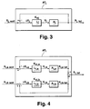
- FIG. 3 the signal flow diagram of such a position-controlled drive arrangement AT j with a single axis in the second axial direction j is shown in a highly simplified representation.
- the drive arrangement AT j is an NC position setpoint specification x j, soll specified by a numerical control unit, not illustrated.
- the drive A j moves to a position x j , is on.
- This position serves as a control variable x j, is for a position controller L j , the control error .DELTA.x j , ie the difference from controlled variable x j, is and setpoint x j , soll , is supplied as an input variable.
- the position controller L j determined from the control error Ax j a speed of the final drive A j as the control variable v j by the control error Ax j with a gain Kv is multiplied by j.
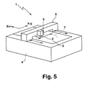
- FIG. 4 is the corresponding signal flow plan of a drive assembly AT i of the first axial direction i shown with two individual axes a and b, which interact without special measures.
- the position setpoint is here separately for a first and a second final drive A i, a, A i, b, ie, from a first target value x i, a soll, a first position x i, a is referred to as a control variable to form an as drag error Control error .DELTA.x i, a subtracted and to the drive A i, a associated controller L i, a supplied, which determines a manipulated variable v i, a for the drive A i, a by multiplication with a gain factor Kv i, a .
- a regulation of a second controlled variable x i, b is carried out correspondingly for the second drive A i, b .
- the two positions X i, a and X i, b is then superimposed to a total position x i, i is along the first axial direction.
- This object is achieved according to the invention by predetermining the control factor as a function of a gain specified for the first final drive and a gain specified for the second final drive, wherein the amplification factor specified for the second final drive represents an effective gain factor for the first drive arrangement and at least one additional, acting in a second axial direction
- the control factor represents an effective gain factor for the first drive arrangement and at least one additional, acting in a second axial direction
- the further drive arrangement is in this case constructed analogously to the drive arrangement acting in the first axial direction, ie, a variable proportional to the control error of the first final drive is supplied to the second final drive of this drive arrangement, which of the uniform for all axis directions, effective gain factor and the gain factor of the first in the second axis acting axle drive depends.
- Kv e is fixed then Kv i, a or Kv i, b can be determined from (*).
- Kv e is set by a numerical controller. If Kv e is to be variable as a function of the position along the trajectory, it must already be at the Path planning are defined, what happens in a path planning unit (see below). Due to the above-described specification of an identical effective gain Kv e along all axial directions, the drive arrangements act in the same way, regardless of how many axes the drive arrangements have. As a result, the aforementioned path distortions can be largely prevented, the design of the controlled NC axes does not matter, so that they can be performed in all known constructions, so for example as direct drives.
- the numerical control of the machine tool is assigned to specify the setpoint value, the control factor and the gain factors and possibly further variables, as a rule, a function module designated below as a path planning unit.
- the path planning unit is known all the relevant variables for the mobility of the individual axes and their control circuits (maximum values for achieving a desired accuracy). From the parts program that includes the workpiece geometry to be machined (alternatively, a taught path can be used as basis), it is determined and determined which motion components are to be output to the axial directions in such a way that optimizes the web movement in time and in terms of precision he follows.
- the path planning unit In the path planning unit, transformations (from space to machine axes and back) and interpolation algorithms for setting the desired position value to the individual axes are accomplished by known methods for the interaction of all machine axes.
- the path planning unit thus provides a parameter set for the optimized trajectory of the trajectory, which is used in the execution of the movement program of a numerical control unit for position control of the final drives.
- the web planning unit thus coordinates the drive arrangements acting in different directions before the trajectory of the trajectory.
- a second desired value for the second final drive is specified, wherein a division of a common setpoint for the first drive assembly in the first and second setpoint depending on the characteristics of the final drives and a predetermined trajectory for moving one through the drive assemblies moving tool and / or workpiece takes place.
- the path planning unit additionally makes the division of the movement in one axial direction into two or more individual axes.
- the kinematic ambiguities are resolved with respect to the resulting target positions, which are caused by the presence of the two or more axes in one axial direction. This is done by specifying the coupling of the individual axes (a, b) and by the precisely planned specification of the position setpoint values for the path to be traversed, taking into account and optimized tuning to the physical movement possibilities (limitations) of the individual axes.
- the common setpoint is divided into three or more setpoint components.
- the kinematically coupled individual axes which are connected in series one behind the other, are designed in such a way that they can individually approach and hold positions in the expected precision. So it is not a question of detecting design-related axis inaccuracies or workpiece deviations separately (using a separate sensor) and compensating with the coupled additional axis. Nevertheless, the method described can also be used advantageously for this task. In this case, for example, no own setpoint path is interpolated for the second individual axis, but its setpoint position is kept constant at zero. Thus, the second axis connected as additional axis acts as a leading axis purely for the reduction of the following error in order to reach Kv e . Of course, this can be done for one, several or all axial directions of the machine tool.
- the amount of the effective amplification factor is preferably predefined between an amplification factor optimized for the first final drive and an amplification factor optimized for the second final drive, wherein "between” is to be interpreted as meaning that the interval limits are included.
- the optimized amplification factors represent the maximum possible values which are determined according to the usual optimization criteria - without taking into account a coupling of the individual axes - which the path planning unit or the numerical control unit are known.
- the position of the axle drives is regulated, the speeds of the axle drives being set as manipulated variables.
- the speed and current of one (or all) drives can be specified by the controller directly as setpoints for the relevant controller.
- the associated position controller is thereby bypassed (possibly partially) and only acts for remaining deviations.
- first final drive On which an additional axis with a smaller travel path (second final drive) is constructed.
- first final drive is referred to as a slow final drive
- second final drive as a faster final drive
- the first axle drive is completely or partially pulse-decoupled from the second axle drive.
- a force is exerted on the other axle drive during the acceleration of one of the final drives, which force is compensated by the impulse decoupling. This can be done by an opposite movement of a mass provided for compensation taking into account the relative masses of the drives (so-called mass balance).
- the second axle drive for this purpose can also be attached via an elastic spring means or a damping means on the first axle drive, such as in the DE 198 10 996 A1 which is incorporated herein by reference in its entirety.
- the impulse decoupling Due to the impulse decoupling is the Motion of the second final drive with respect to the first axle drive, so that the well-known optimization criteria can be used without consideration of interfering effects to determine the control factors of the final drives. It is also possible to completely or partially dispense with the impulse decoupling if, based on the movements to be carried out, the individual axes are embodied in their disturbing behavior in such a way that the repercussions of the axes a and b give each other tolerable deviations.
- correction values for the supply to a current regulator and / or a rotational speed controller of the first and / or second final drive are generated from the mass and acceleration of the first final drive and / or the mass and acceleration of the second final drive.
- This variant is advantageous if no or partial impulse decoupling is carried out and the axes are too heavy and too sluggish, so that deviations occur that are no longer within the tolerance range.
- correction values are generated by the path planning unit or the numerical control unit from the accelerations a a and a b known from the interpolation and the masses of the axes (m a and m b ) which pre-control the current regulators, possibly also the speed controllers of the final drives be switched on each other.
- the effective amplification factor and / or the amplification factor prescribed for the first final drive is varied as a function of the position along the trajectory for the movement of a tool and / or workpiece moved by the drive arrangements along a predetermined trajectory.
- the gain factors are set as control parameters for a trajectory given by the parts program in advance in a numerical control and remain constant along the trajectory.
- the effective amplification factor is increased in path sections in which no movement occurs at least in one axial direction. If one (or more) axis directions are not involved in the movement, then these do not give rise to any path distortions.
- the slowest and / or the fastest axis drives of the drive arrangements of all axial directions of the machine tool have the same amplification factor for determining a manipulated variable from a controlled variable and preferably have identical frequency response.
- the individual axes (a, b) of all machine axis directions should be matched to one another. Such a coordination of all axes results automatically when the slowest and / or fastest axle drives are synchronized as described above.
- a desired value of the first and / or the second axle drive of at least the first drive arrangement is modified with a sensor control signal.
- the drive arrangement is associated with a sensor, which deviations of the current positioning, which is the basis of the programmed nominal path (ie, remaining deviations of the axes), determined by a desired path, such as a provided with surface deviations workpiece contour. Any "off-set" value is already included in the setpoint; according to z. B. the nominal distance nozzle plate in the distance control of a machine tool for laser machining of a workpiece.
- the invention is also realized in a web planning unit, comprising a computer program product for carrying out all steps of the method described above.
- the path planning unit will be given the machine tool characteristics (e.g., mechanical limitations of the final drives) and the part program, i. the trajectory to be generated, specified. From these data, the path planning unit determines a parameter set for the nominal values of the individual axes, the effective amplification factor, and the velocity gains of the individual axes.
- the parameter set can be stored by the web planning unit and subsequently retrieved by a numerical control unit, as soon as a predetermined trajectory with the machine tool is to be traced.
- the web planning unit can be integrated in the machine tool - in particular in a numerical control unit of the same or independent of this.
- a conventional computer can be used as a path planning unit if it is equipped with a suitable computer program product for carrying out the method.
- control unit is designed to specify a control factor for supplying the proportional variable as a function of a gain factor given to the first final drive and a gain factor specified for the second final drive, wherein the second Final drive specified Amplification factor forms an effective gain factor for the first drive assembly and at least one further, acting in a second axial direction drive unit.
- control unit is designed to specify a second setpoint value for the second final drive and the machine tool preferably has a path planning unit which is designed to divide a common setpoint for the first drive arrangement into the first and the second setpoint value as a function of the Properties of the final drives and a predetermined trajectory to move a moving through the drive assemblies tool and / or workpiece to make.
- the path planning thus defines which components of the movement in an axial direction the first or second final drive has to execute. This depends on the geometry of the workpiece to be machined and on the design-related limitations of the (all) individual interpolating machine axes. Limitations exist with respect to travel distances, speeds, accelerations and jerks as well as the position control factors; these are questions of interpretation.
- the motion components are output via the position command value specification (interpolation) to all axis drives.
- the axis drives are then separately controlled according to known position interpolation methods.
- the amount of the effective amplification factor is between an amplification factor optimized for the first final drive and an amplification factor optimized for the second final drive.
- the effective amplification factor is set by the path planning unit depending on the driving ability of the final drives between these two values.
- the controller error of the first axle drive is supplied to the second axle drive and the control factor is the difference between the effective gain factor and the gain specified by the first axle drive.
- control error of the first final drive is supplied to the controller of the second final drive, wherein the difference between the effective gain factor and the first gain factor is divided by the effective gain factor to form the control factor.
- the above-described formula (***) for the gain factor of the second final drive v i, b (Kv e - Kv i, a ) / Kv e ⁇ x i, a + ⁇ x i, b ) Kv e implemented by control technology.
- the controllers are position controllers for determining the speed setpoints of the final drives as manipulated variables. This corresponds to the typical application. In addition or as an alternative to the position control, it is also possible to carry out a speed control and / or a speed control in the manner described above.
- the second final drive is constructed on the first final drive. Movement in one axial direction can be realized by superimposing the movements of a slow basic axis with a large travel distance and a more dynamic additional axis with usually smaller travel distance.
- the machine tool can produce, for example for the X and Y directions, a series of small circle contours which are close to each other, exclusively from the dynamic individual axes , about Xb and Yb are executed.
- the process from circle to circle can be accomplished predominantly by less dynamic fundamental axes, Xa, Ya with a substantially constant, high traversing speed, and the dynamic auxiliary axes Xb, Yb drive the small circle contours high accelerations.
- the advantageous manner is carried out such that the corners for the less dynamic basic axes (Xa, Ya) are rounded (ie corresponding to their possibilities) larger, and the remaining corner contours are traversed by the dynamic additional axes (Xb, Yb).
- the division of the web movement depending on the part program is here, as already mentioned above, accomplished by the web planning unit.
- the bearing of the second final drive on the first final drive is completely or partially pulse-decoupled.
- Pulse decoupling can be achieved by mass balancing or suitable e.g. spring-mounted storage of the drives are produced.
- control unit is designed to generate correction values from the mass and acceleration of the first final drive and / or the mass and acceleration of the second final drive.
- machine tool has means for supplying the correction values to a current controller and / or a speed controller of the first and / or second axle drive. If no mechanical impulse decoupling is carried out or if the desired tolerances can not be achieved with this, the impulse decoupling can be carried out by means of a control by means of the correction values.
- the machine tool has a path planning unit which is designed to move the movement of a tool and / or workpiece moved by the drive arrangements along a predetermined trajectory the effective gain factor and / or the first gain of the first final drive depending on the position to change along the trajectory.
- the set of values passed on by the path planning unit to the numerical control unit serves to optimally optimize the control loop parameters of the final drives. This is particularly advantageous when it is not necessary to move through part of the trajectory in an axial direction which has the or a particularly sluggish drive arrangement.
- the effective gain factor which is otherwise limited by the inertia of this drive arrangement, can therefore be increased in this part of the trajectory.
- the slowest and / or fastest axis drives of all axial directions of the machine tool have a common amplification factor and preferably have identical frequency response.
- the machine tool has at least one sensor controller which modifies a setpoint variable of the first and / or the second final drive with a sensor control signal.
- the effectiveness (sharpness) of the sensor engagement can be predetermined via the factors Kp, Tn, Tv of the at least one sensor position controller, which can generally be embodied as a PID controller.
- Kp, Tn, Tv of the at least one sensor position controller which can generally be embodied as a PID controller.
- a single sensor controller is provided whose output signal modifies the setpoint values of all axle drives in an axial direction, or a separate sensor controller for one or a group of axle drives in one axial direction can be provided.
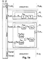
- Fig. 1a , b each show a signal flow plan of a position control of drive arrangements AT 1 to AT n of a machine tool, which are required for tracing a trajectory and act along axial directions 1,..., n.
- the number of drive arrangements n required for tracing a trajectory coincides with the total number of drive arrangements present on the machine tool.
- a first group of drive arrangements AT i each have a single final drive A j (cf. Fig. 3 ), a second group of drive arrangements AT i , two axle drives A i, a, A i, b (see FIG. Fig. 4 ) It is understood that in general more than two axle drives can act in one axial direction.
- the movement components predetermined in the path planning unit BP are output via the desired position value specification (interpolation) to all drive arrangements AT 1 to AT n .
- drive arrangements AT j with a single axis drive A j a single setpoint x j shall be predetermined, in drive arrangements AT i with two axis drives, the position setpoint to the individual axle drives A i, a , A i, b split, ie, a first final drive A.
- the trained as a servo drives drives A i, a , A i, b , A j are therefore separately controlled by known methods separately.
- the numerical control unit PM determines an effective amplification factor Kv e for all drive arrangements AT 1 to AT n . In the case of drive arrangements AT j, this is supplied to the associated controller L j for position control with only one final drive A j . In drive arrangements AT i with two axle drives A i, a , A i, b , the effective gain Kv e the controller L a of the second final drive A i, b supplied, which in the present case on the first final drive A i, a constructed and dynamic as this is.
- the value of the effective amplification factor Kv e in the axial direction i preferably lies between the maximum amplification factors (Kv values) Kv i, a or Kv i, b of the two final drives A i, a and A i, b in the latter Axial direction (cf. Fig. 4 ), which are determined according to the usual optimization criteria.
- Kv values maximum amplification factors
- the slowest of the drive arrangements AT 1 to AT n is used for this (possibly sectionally variable) uniform determination of the effective gain Kv e , since this acts limiting for all axis directions.
- path distortions due to differences in the following errors of different axial directions i, j can be substantially reduced.
- supply means that the proportional variable forms an input variable for the final drive or the controller, which as a rule is supplied together with other input variables at a summation point.
- Fig. 1a has the second controller for generating the manipulated variable v i, b for the second final drive A i, b a first control section L i, b (b) and a second, parallel control section L i, b (b) , wherein an input signal of the first Control section L i, b (b) is a control error Ax i, b of the second final drive A i, b and an input signal of the second control section L i, b (a) is a control error .DELTA.x i, a of the first final drive A i, a .
- the numerical control unit PM provides a control factor for the second control section L i, b (a) , which serves as a supply means for supplying the proportional amount to the second final drive A i , b, from the difference of the effective gain Kv e and the Amplification factor Kv i, a of the first final drive A i, b is formed, ie Kv e - Kv i, a .
- a regulator L i, b not divided into two control sections is used, to which a control factor, which in this case is formed by the difference between the effective amplification factor (Kv e ) and the first amplification factor (K), is given via a connection serving as a supply means.
- the control unit PM can keep the amplification factors constant during the entire execution of an NC program for tracing a trajectory. This applies in particular to the gain factor Kv i, a of the first final drive A i, a , if this is a less dynamic basic axis.
- the slowest of the drive arrangements AT 1 to AT n has a limiting effect for all axial directions 1 to n of the machine tool.
- the effective amplification factor Kv e is preferably carried out in track sections, in which one (or more) axial directions is uninvolved / are, so that this results in no path distortions.
- the gain factors Kv i, a of the first axle drives A i, a can also be changed as a function of the position along the trajectory.
- the gain factors Kv e can be increased without negative effects, so that the maximum mobility of the individual axle drives can be optimally utilized.
- the specification of the dynamic amplification factors is accomplished here in the path planning unit BP.
- the axle drives A i, a , A i, b, A j of all axial directions 1 to n can also be individually matched to one another.
- FIG Fig. 5 The procedure described above can be used in particular for the control of drive arrangements of a machine tool 1 , as shown schematically in FIG Fig. 5 is shown.
- a workpiece 3 is arranged there for processing by a tool 2 fixed on a table 4 .
- the tool 2 is movably mounted on a holding device 6 in the X-direction.
- the holding device 6 is in turn arranged movably in the Y-direction on a portal 5, which is movable even in the X direction.
- the holding device 6 has a lower mass than the portal 5 and the tool 2. Accordingly, movements in the X direction can be made faster by relative movement of the tool 2 to the holding device 6 than by movement of the portal 5.
- the portal 5 and the tool 2 are driven by a drive assembly AT i as in Fig.
- the first axle drive A i, a serves to move the gantry 5 on the table 4
- the second final drive A i, b serves to move the tool 2 along the holding device 6.
- the movement of the holding device 6 in the Y direction takes place in accordance with an axle drive A j a drive assembly AT j with only one final drive A j , as in Fig. 1 shown.
- a trajectory 7 planned in the path planning unit BP is thus traced as precisely and quickly as possible.
- the reaction of the one final drive A i, a to the other final drive A i, b must possibly be taken into account when designing the drive arrangement AT i .
- a mass balance can be performed, ie the portal 5 in Fig. 5 may have a mass (not shown) which performs a corresponding counter-movement in a jerky movement of the tool 2 in the X direction for compensation.
- the portal 5 can be mounted on the table 4 elastically resilient or damping to produce a pulse compensation.
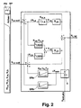
- a pulse compensation is not provided or is only partially carried out, it is possible, as in Fig. 2 for a drive arrangement AT i in the axial direction i, in the path planning unit BP the accelerations a i, a and a i, b known by the interpolation of the trajectory and the masses m i, a , m i, b of the axes (a and b) to use to generate correction values that are in Fig. 2 not graphically illustrated current regulators and possibly also speed regulators of the final drives A i, a and A i, b are connected to each other pilot-controlled.
- Fig. 2 shows for this purpose a sensor S , which deviations ⁇ x sen the position x i, is along the trajectory to be executed, which is based on the programmed nominal path (ie, remaining deviations of the axes) of a nominal path x soll, abs , about one provided with surface deviations Workpiece contour, determined. Any "off-set" value is already included in the current value x soll, abs of the nominal path; corresponding to approximately the nominal distance nozzle-plate in the distance control of a laser processing machine.
- the Deviation ⁇ x sen is fed to two sensor position controllers SR a , SR b , which are each assigned to one of the final drives A i, a , A i, b and generate a sensor control signal which is to add a respective desired value signal x i, a and x i, b becomes.
- the effectiveness (sharpness) of the sensor engagement can be specified via the factors Kp , Tn , Tv of the sensor position controllers SR a , SR b , which are in Fig. 2 are shown as PID controller. It is understood that a single sensor controller can be used which generates a sensor signal only for one final drive A i, a or A i, b or for both axle drives A i, a , A i, b together.
- the sensor S does not have to be a sensor aligned or active in the axial direction i, ie the positional deviation X soll determined by the sensor S , abs may also be a distributed, transformed component of a sensor signal, namely the case that the signal affects a plurality of axial directions i, that is, the sensor S is not fixed in an axial direction aligned (eg in a 3-D machining).
- identical amplification factors of the respective sensor drives SR a , SR b assigned to each final drive are to be used for all axis directions 1, or to transform the positional advance thereof in the case of just one sensor controller.
- the signal of a force sensor for example, for the Antikkraftregelung during grinding
- the (the) current controller of the Achsantriebe A i, a , A i, b can be switched on vor Kunststoffnd example, the (the) current controller of the Achsantriebe A i, a , A i, b .
- sensor signals can have strong noise components, which must be smoothed by low-pass filtering so that the excitation of the individual axis drives is not too high-frequency. The consideration of this fact is familiar to the skilled person.
Abstract
Description
Die vorliegende Erfindung betrifft ein Verfahren zum Koordinieren von in unterschiedlichen Achsrichtungen wirkenden Antriebsanordnungen einer Werkzeugmaschine, umfassend die Schritte: Vorgeben eines ersten Sollwerts für einen ersten geregelten Achsantrieb einer in einer ersten Achsrichtung wirkenden, ersten Antriebsanordnung, sowie Vorgeben eines Regelfaktors für das Zuführen einer zu einem Regelfehler des ersten geregelten Achsantriebs proportionalen Größe an wenigstens einen zweiten geregelten Achsantrieb der ersten Antriebsanordnung, sowie eine Bahnplanungseinheit zur Durchführung des Verfahrens. Weiterhin betrifft die Erfindung eine Werkzeugmaschine mit: einer in einer ersten Achsrichtung wirkenden Antriebsanordnung, die einen ersten Achsantrieb mit einem zugeordneten Regler aufweist, einer Steuerungseinheit zur Vorgabe eines Sollwerts an den Regler des ersten Achsantriebs, sowie Mittel zum Zuführen einer zu einem Regelfehler des ersten Achsantriebs proportionalen Größe an wenigstens einen zweiten Achsantrieb der ersten Antriebsanordnung oder einen dem zweiten Achsantrieb zugeordneten Regler.The present invention relates to a method for coordinating drive arrangements of a machine tool acting in different axial directions, comprising the steps of: predetermining a first setpoint value for a first controlled final drive of a first drive arrangement acting in a first axial direction, and predetermining a control factor for supplying one to one Control error of the first controlled axle drive proportional size at least a second controlled final drive of the first drive assembly, and a web planning unit for performing the method. Furthermore, the invention relates to a machine tool having: acting in a first axial direction drive assembly having a first final drive with an associated controller, a control unit for specifying a desired value to the controller of the first final drive, and means for supplying a to a control error of the first final drive proportional size to at least one second axle drive of the first drive arrangement or a controller associated with the second axle drive.
Ein derartiges Verfahren und eine derartige Werkzeugmaschine sind beispielsweise in der Patentanmeldung
Gegenstand der folgenden Ausführungen sind Werkzeugmaschinen, deren kinematischer Aufbau eine Anzahl n von Achsrichtungen zum Nachfahren einer vorgegebenen Bahnkurve umfasst, wobei in jeder Achsrichtung jeweils eine Antriebsanordnung wirkt. Eine beliebige Zahl, mindestens aber eine Antriebsanordnung ist ausgeführt durch zwei oder mehr einzelne, geregelte Achsantriebe (a, b), welche sowohl kinematisch als auch die einzelnen Messsysteme betreffend hintereinander liegend angeordnet sind. Am Wirkungsort (Werkzeugeihgriffspunkt) ergibt sich eine kinematische Überlagerung in der betreffenden Achsrichtung. Als Achsrichtungen werden hierbei sowohl translatorische Achsen als auch rotatorische Achsen bezeichnet. Sind letztere z.B. über ein Gelenk miteinander verbunden, ist gegebenenfalls eine Transformation von Raum- in Maschinenkoordinaten und zurück erforderlich.The subject of the following embodiments are machine tools whose kinematic structure comprises a number n of axial directions for descending a includes predetermined trajectory, wherein in each axial direction in each case acts a drive arrangement. Any number, but at least one drive arrangement is carried out by two or more individual, controlled axle drives (a, b), which are arranged both kinematically and the individual measuring systems in relation to each other. At the point of action (tool access point) there is a kinematic superimposition in the relevant axial direction. As axial directions here both translational axes and rotational axes are referred to. If the latter are connected to one another, for example via a joint, a transformation from spatial to machine coordinates and back is possibly necessary.
Im Folgenden werden die Achsantriebe auch kurz als Achsen (a, b) bezeichnet. Als Achsen dienen vorliegend bevorzugt Servoantriebe, d.h. Antriebe mit hoher Dynamik (schnellem Beschleunigen und Abbremsen) sowie guter Genauigkeit beim Erreichen der Sollwerte. Bei den hier beschriebenen Servoantrieben sind die Antriebsebenen kaskadiert, sodass nur Sollwerte für die Positionen vorgegeben werden müssen. Alternativ kann aber auch eine direkte Regelung der unterlagerten Regelkreise (Drehzahl- bzw. Stromregelung) vorgenommen werden (sog. Vorsteuerung). Hierbei wird der Lageregler bzw. (für den Strom) der Drehzahlregler umgangen und wirkt nur noch für die Abweichungen.In the following, the axle drives are also referred to as axles (a, b) for short. Serving as axes in the present case are preferably servo drives, i. Drives with high dynamics (fast acceleration and deceleration) and good accuracy when reaching the setpoints. In the servo drives described here, the drive levels are cascaded so that only setpoints for the positions must be specified. Alternatively, however, a direct control of the subordinate control loops (speed or current control) can be made (so-called feedforward control). In this case, the position controller or (for the current) the speed controller is bypassed and only works for the deviations.
Was die Anordnung der Achsen (a,b) angeht, sind mehrere Varianten möglich. So ist es beispielsweise möglich, dass beide Achsen (a, b) einzeln aufgebaut sind, etwa wenn sich Werkzeug und Werkstück bewegen sollen. Alternativ kann eine Achse (etwa b) auf der anderen Achse (dann a) aufgebaut sein, also deren Bewegung mit ausführen. Im Vordergrund des Interesses stehen momentan Aufbauten, bei welchen Zusatzachsen mit hoher Dynamik und geringen Verfahrbereichen angeordnet sind auf Grundachsen mit großen Verfahrbereichen und geringerer Dynamik.As far as the arrangement of the axes (a, b) is concerned, several variants are possible. So it is possible, for example, that both axes (a, b) are constructed individually, such as when tool and workpiece to move. Alternatively, an axis (about b) on the other axis (then a) can be constructed, so perform their movement with. In the foreground of interest are currently superstructures in which additional axes with high dynamics and low travel ranges are arranged on basic axes with large travel ranges and lower dynamics.
Die entlang weiterer Achsrichtungen wirkenden Antriebsanordnungen können entweder als Einzelachsen aufgebaut sein, oder ebenfalls zwei oder mehr Achsen umfassen, die wie oben im Zusammenhang mit der ersten Achsrichtung beschrieben gekoppelt sind. Im Folgenden werden zwei beliebige Achsrichtungen i, j aus der Anzahl n von Achsrichtungen herausgegriffen, wobei die Antriebsanordnung der ersten Achsrichtung i zwei Achsen umfasst, wohingegen die Antriebsanordnung der zweiten Achsrichtung j eine einzelne Achse aufweist.The drive arrangements acting along further axial directions can either be constructed as individual axles or likewise comprise two or more axles which are coupled as described above in connection with the first axial direction. In the following, two arbitrary axial directions i, j are selected from the number n of axial directions, wherein the drive arrangement of the first axial direction i comprises two axes, whereas the drive arrangement of the second axial direction j has a single axis.
In
In
Wird eine Werkzeugmaschine mit den in
Für die Korrektur von Bahnverzerrungen bei mehreren Antrieben entlang einer Achsrichtung ist es aus der oben genannten Patentanmeldung
Es ist die Aufgabe der vorliegenden Erfindung, ein Verfahren, eine Bahnplanungseinheit zur Durchführung des Verfahrens sowie eine Werkzeugmaschine der eingangs genannten Art dahingehend weiterzubilden, dass die oben beschriebenen Bahnverzerrungen weitestgehend vermieden werden können.It is the object of the present invention to further develop a method, a path planning unit for carrying out the method and a machine tool of the type mentioned at the outset such that the path distortions described above can be largely avoided.
Diese Aufgabe wird erfindungsgemäß gelöst durch Vorgeben des Regelfaktors in Abhängigkeit von einem dem ersten Achsantrieb vorgegebenen Verstärkungsfaktor und einem dem zweiten Achsantrieb vorgegebenen Verstärkungsfaktor, wobei der dem zweiten Achsantrieb vorgegebene Verstärkungsfaktor einen effektiven Verstärkungsfaktor für die erste Antriebsanordnung und mindestens eine weitere, in einer zweiten Achsrichtung wirkende Antriebsanordnung bildet.. Üblicherweise wird nicht nur die zweite, sondern alle zum Nachfahren einer vorgegebenen Bahnkurve verwendeten Antriebsanordnungen mit demselben effektiven Verstärkungsfaktor beaufschlagt, wodurch die oben beschriebenen Bahnverzerrungen wirksam reduziert werden können. Weiterhin wird durch die oben beschriebene Festlegung des Regelfaktors die Wirkung der höher dynamischen Achse auf das für ein gutes Bahnverhalten benötigte Maß begrenzt. Unter dem Vorgeben von Verstärkungsfaktoren kann je nach Anwendungsfall verstanden werden, dass diese für das Nachfahren einer vorgegebenen Bahnkurve von Anfang an fest eingestellt werden oder dass diese variabel vorgegeben werden, d.h. in Abhängigkeit von der Position entlang der Bahnkurve veränderlich sind.This object is achieved according to the invention by predetermining the control factor as a function of a gain specified for the first final drive and a gain specified for the second final drive, wherein the amplification factor specified for the second final drive represents an effective gain factor for the first drive arrangement and at least one additional, acting in a second axial direction Usually, not only the second, but all drive arrangements used for descending a given trajectory are subjected to the same effective amplification factor, whereby the path distortions described above can be effectively reduced. Furthermore, by the above-described determination of the control factor, the effect of the higher dynamic axis on that for a good Track behavior required limited measure. Under the specification of gain factors can be understood depending on the application, that they are set for the descendants of a given trajectory from the beginning or that they are variable, ie, are variable depending on the position along the trajectory.
Der effektive Verstärkungsfaktor wird bei einer weiteren Antriebsanordnung in der zweiten Achsrichtung, welche nur eine einzige Achse aufweist (vgl.
Bei mehreren Antrieben entlang einer Achsrichtung (z.B. i) ist der effektive Verstärkungsfaktor definiert als derjenige Verstärkungsfaktor, der sich bei der Verwendung eines einzigen Antriebs in dieser Achsrichtung ergeben würde, d.h. für zwei Antriebe (a, b) in Achsrichtung i, welche jeweils eine Lageregelung mit Verstärkungsfaktor Kvi,a bzw. Kvi,b aufweisen stehen diese Größen folgendermaßen mit dem effektiven Verstärkungsfaktor Kve in Beziehung: ![]()
![]()
Steht Kve fest, so können Kvi,a oder Kvi,b aus (*) bestimmt werden. Für gewöhnlich wird Kve von einer numerischen Steuerung festgelegt. Soll Kve in Abhängigkeit von der Position entlang der Bahnkurve variabel sein, muss er bereits bei der Bahnplanung festgelegt werden, was in einer Bahnplanungseinheit geschieht (s.u.). Durch die oben beschriebene Vorgabe eines identischen effektiven Verstärkungsfaktors Kve entlang aller Achsrichtungen wirken die Antriebsanordnungen auf die gleiche Weise, unabhängig davon, wie viele Achsen die Antriebsanordnungen aufweisen. Hierdurch können die oben genannten Bahnverzerrungen weitgehend unterbunden werden, wobei die Bauweise der geregelten NC- Achsen keine Rolle spielt, sodass diese in allen bekannten Bauweisen ausgeführt sein können, also beispielsweise auch als Direktantriebe.If Kv e is fixed then Kv i, a or Kv i, b can be determined from (*). Usually, Kv e is set by a numerical controller. If Kv e is to be variable as a function of the position along the trajectory, it must already be at the Path planning are defined, what happens in a path planning unit (see below). Due to the above-described specification of an identical effective gain Kv e along all axial directions, the drive arrangements act in the same way, regardless of how many axes the drive arrangements have. As a result, the aforementioned path distortions can be largely prevented, the design of the controlled NC axes does not matter, so that they can be performed in all known constructions, so for example as direct drives.
Der numerischen Steuerung der Werkzeugmaschine ist zur Vorgabe des Sollwertes, des Regelfaktors sowie der Verstärkungsfaktoren und ggf. weiterer Größen in der Regel ein im Folgenden als Bahnplanungseinheit bezeichneter Funktionsbaustein zugeordnet. Der Bahnplanungseinheit sind sämtliche relevante Größen zum Bewegungsvermögen der einzelnen Achsen sowie von deren Regelkreisen (Maximalwerte für das Erreichen einer gewünschten Genauigkeit) bekannt. Aus dem Teileprogramm, das die zu bearbeitende Werkstückgeometrie umfasst (alternativ kann auch eine geteachte Bahn zu Grunde gelegt werden), wird ermittelt und festgelegt, welche Bewegungsbestandteile an die Achsrichtungen ausgegeben werden sollen, in der Weise, dass die Bahnbewegung zeitlich und bezüglich der Präzision optimiert erfolgt. Dabei werden in der Bahnplanungseinheit für das Zusammenspiel aller Maschinenachsen Transformationen (von Raum- in Maschinenachsen und zurück), sowie Interpolationsalgorithmen zur Lagesollwertvorgabe an die einzelnen Achsen nach bekannten Verfahren bewerkstelligt. Die Bahnplanungseinheit liefert somit einen Parametersatz für das optimierte Nachfahren der Bahnkurve, welcher bei der Ausführung des Bewegungsprogramms von einer numerischen Steuerungseinheit zur Lageregelung der Achsantriebe herangezogen wird. Die Bahnplanungseinheit koordiniert somit die in unterschiedliche Richtungen wirkenden Antriebsanordnungen vor dem Nachfahren der Bahnkurve.The numerical control of the machine tool is assigned to specify the setpoint value, the control factor and the gain factors and possibly further variables, as a rule, a function module designated below as a path planning unit. The path planning unit is known all the relevant variables for the mobility of the individual axes and their control circuits (maximum values for achieving a desired accuracy). From the parts program that includes the workpiece geometry to be machined (alternatively, a taught path can be used as basis), it is determined and determined which motion components are to be output to the axial directions in such a way that optimizes the web movement in time and in terms of precision he follows. In the path planning unit, transformations (from space to machine axes and back) and interpolation algorithms for setting the desired position value to the individual axes are accomplished by known methods for the interaction of all machine axes. The path planning unit thus provides a parameter set for the optimized trajectory of the trajectory, which is used in the execution of the movement program of a numerical control unit for position control of the final drives. The web planning unit thus coordinates the drive arrangements acting in different directions before the trajectory of the trajectory.
Bei einer bevorzugten Variante des erfindungsgemäßen Verfahrens wird ein zweiter Sollwert für den zweiten Achsantrieb vorgegeben, wobei eine Aufteilung eines gemeinsamen Sollwerts für die erste Antriebsanordnung in den ersten und zweiten Sollwert in Abhängigkeit von den Eigenschaften der Achsantriebe und einer vorgegebenen Bahnkurve zur Bewegung eines durch die Antriebsanordnungen bewegten Werkzeugs und/oder Werkstücks erfolgt.In a preferred variant of the method according to the invention, a second desired value for the second final drive is specified, wherein a division of a common setpoint for the first drive assembly in the first and second setpoint depending on the characteristics of the final drives and a predetermined trajectory for moving one through the drive assemblies moving tool and / or workpiece takes place.
Die Bahnplanungseinheit nimmt neben der Aufteilung der Bewegungsbestandteile in verschiedene Achsrichtungen zusätzlich die Aufteilung der Bewegung in einer Achsrichtung auf zwei oder mehr Einzelachsen vor. Hierbei werden die kinematischen Mehrdeutigkeiten bezüglich der resultierenden Sollpositionen, welche durch das Vorhandensein der zwei oder mehr Achsen in einer Achsrichtung entstehen, aufgelöst. Dies erfolgt durch Festlegung der Kopplung der Einzelachsen (a, b) sowie durch die genau geplante Vorgabe der Lagesollwerte für die zu verfahrende Bahn unter Berücksichtigung und optimierter Abstimmung auf die physikalischen Bewegungsmöglichkeiten (Begrenzungen) der Einzelachsen. Bei Vorhandensein von mehr als zwei Einzelachsen wird der gemeinsame Sollwert selbstverständlich in drei oder mehr Sollwertanteile aufgeteilt.In addition to the division of the movement components in different axial directions, the path planning unit additionally makes the division of the movement in one axial direction into two or more individual axes. Here, the kinematic ambiguities are resolved with respect to the resulting target positions, which are caused by the presence of the two or more axes in one axial direction. This is done by specifying the coupling of the individual axes (a, b) and by the precisely planned specification of the position setpoint values for the path to be traversed, taking into account and optimized tuning to the physical movement possibilities (limitations) of the individual axes. In the presence of more than two individual axes of course, the common setpoint is divided into three or more setpoint components.
Die in ihrer Wirkung hintereinander geschalteten, kinematisch gekoppelten Einzelachsen sind dabei so ausgeführt, dass sie einzeln Positionen in der erwarteten Präzision anfahren und halten können. Es geht hier also nicht darum, bauartbedingte Achsungenauigkeiten oder etwa auch Werkstückabweichungen separat (durch einen eigenen Sensor) zu erfassen und mit der gekoppelten Zusatzachse zu kompensieren. Dennoch kann das beschriebene Verfahren auch für diese Aufgabenstellung vorteilhaft angewendet werden. In diesem Fall wird z.B. keine eigene Sollbahn für die zweite Einzelachse interpoliert, sondern deren Sollposition konstant auf Null gehalten. Somit fungiert die als Zusatzachse geschaltete zweite Achse als eine Vorlaufachse rein zur Reduktion des Schleppabstandes, um Kve zu erreichen. Selbstverständlich kann dies für eine, mehrere oder sämtliche Achsrichtungen der Werkzeugmaschine erfolgen.The kinematically coupled individual axes, which are connected in series one behind the other, are designed in such a way that they can individually approach and hold positions in the expected precision. So it is not a question of detecting design-related axis inaccuracies or workpiece deviations separately (using a separate sensor) and compensating with the coupled additional axis. Nevertheless, the method described can also be used advantageously for this task. In this case, for example, no own setpoint path is interpolated for the second individual axis, but its setpoint position is kept constant at zero. Thus, the second axis connected as additional axis acts as a leading axis purely for the reduction of the following error in order to reach Kv e . Of course, this can be done for one, several or all axial directions of the machine tool.
Vorzugsweise wird der Betrag des effektiven Verstärkungsfaktors zwischen einem für den ersten Achsantrieb optimierten Verstärkungsfaktor und einem für den zweiten Achsantrieb optimierten Verstärkungsfaktor vorgegeben, wobei "zwischen" dahingehend zu interpretieren ist, dass die Intervallgrenzen mit umfasst sind. Die optimierten Verstärkungsfaktoren stellen hierbei die maximal möglichen, nach den üblichen Optimierungskriterien - ohne Berücksichtigung einer Kopplung der Einzelachsen - bestimmten Werte dar, welche der Bahnplanungseinheit bzw. der numerischen Steuerungseinheit bekannt sind.The amount of the effective amplification factor is preferably predefined between an amplification factor optimized for the first final drive and an amplification factor optimized for the second final drive, wherein "between" is to be interpreted as meaning that the interval limits are included. The optimized amplification factors represent the maximum possible values which are determined according to the usual optimization criteria - without taking into account a coupling of the individual axes - which the path planning unit or the numerical control unit are known.
Bei einer besonders vorteilhaften Verfahrensvariante wird die Position der Achsantriebe geregelt, wobei als Stellgrößen die Geschwindigkeiten der Achsantriebe eingestellt werden. Dies entspricht dem typischen Anwendungsfall mit kaskadierten Regelkreisen. Es existieren aber auch andere Regelverfahren für die Servoachsen, die das Ziel haben, die sich einstellenden Schleppabstände zu verkleinern und damit die tatsächlich wirksamen Kv-Faktoren zu vergrößern. Beispielsweise können Drehzahl und Strom eines (bzw. aller) Antriebe von der Steuerung direkt als Sollwerte für die betreffenden Regler vorgegeben werden. Der zugehörige Lageregler wird damit (evtl. teilweise) umgangen und agiert nur noch für verbleibende Abweichungen. Das hier beschriebene Verfahren wird bei Anwendung von nicht kaskadierten Antriebsregelungen analog angewandt mit den tatsächlich wirksamen Kv-Faktoren aus Kv = v / Δx bzw. v / Δs.In a particularly advantageous variant of the method, the position of the axle drives is regulated, the speeds of the axle drives being set as manipulated variables. This corresponds to the typical application with cascaded control loops. But there are also other control methods for the servo axes, which have the goal to reduce the trailing distances that arise and thus to increase the actually effective Kv factors. For example, the speed and current of one (or all) drives can be specified by the controller directly as setpoints for the relevant controller. The associated position controller is thereby bypassed (possibly partially) and only acts for remaining deviations. The method described here is applied analogously when using non-cascaded drive controls with the actual effective Kv factors of Kv = v / Δx or v / Δs.
Bei einer weiteren vorteilhaften Variante ist der zweite Achsantrieb auf dem ersten Achsantrieb aufgebaut und wird mit diesem mitbewegt. Dies entspricht dem Fall einer weniger dynamischen Grundachse mit großem Verfahrweg (erster Achsantrieb), auf dem eine Zusatzachse mit geringerem Verfahrweg (zweiter Achsantrieb) aufgebaut ist. Im Folgenden wird der erste Achsantrieb als langsamer Achsantrieb bezeichnet, der zweite Achsantrieb als schneller Achsantrieb, wobei diese Zuordnung selbstverständlich auch umgekehrt vorgenommen werden könnte.In a further advantageous variant of the second axle drive is constructed on the first axle drive and is moved with this. This corresponds to the case of a less dynamic basic axis with a large travel path (first final drive), on which an additional axis with a smaller travel path (second final drive) is constructed. In the following, the first final drive is referred to as a slow final drive, the second final drive as a faster final drive, this assignment could of course also be made vice versa.
Bei einer bevorzugten Weiterbildung dieser Variante wird der erste Achsantrieb von dem zweiten Achsantrieb ganz oder teilweise impulsentkoppelt. Bei aufeinander aufgebauten Achsantrieben wird bei der Beschleunigung eines der Achsantriebe eine Kraft auf den anderen Achsantrieb ausgeübt, die durch die Impulsentkopplung kompensiert wird. Dies kann durch eine gegenläufige Bewegung einer zur Kompensation vorgesehenen Masse unter Berücksichtigung der relativen Massen der Antriebe geschehen (sog. Massenausgleich). Alternativ oder zusätzlich kann der zweite Achsantrieb hierzu auch über ein elastisches Federmittel oder ein Dämpfungsmittel am ersten Achsantrieb befestigt werden, wie beispielsweise in der
Bei einer Weiterbildung dieser Variante werden aus der Masse und Beschleunigung des ersten Achsantriebs und/oder der Masse und Beschleunigung des zweiten Achsantriebs Korrekturwerte für das Zuführen an einen Stromregler und/oder einen Drehzahlregler des ersten und/oder zweiten Achsantriebs erzeugt. Diese Variante ist vorteilhaft, wenn keine oder eine teilweise Impulsentkopplung durchgeführt wird und die Achsen zu schwer und zu träge sind, sodass Abweichungen entstehen, die nicht mehr im Toleranzbereich liegen. In diesem Fall werden aus den durch die Interpolation bekannten Beschleunigungen aa und ab sowie den Massen der Achsen (ma und mb) von der Bahnplanungseinheit oder der numerischen Steuerungseinheit Korrekturwerte generiert, die den Stromreglern, evtl. auch den Drehzahlreglern der Achsantriebe vorsteuernd wechselseitig aufgeschaltet werden.In a development of this variant, correction values for the supply to a current regulator and / or a rotational speed controller of the first and / or second final drive are generated from the mass and acceleration of the first final drive and / or the mass and acceleration of the second final drive. This variant is advantageous if no or partial impulse decoupling is carried out and the axes are too heavy and too sluggish, so that deviations occur that are no longer within the tolerance range. In this case, correction values are generated by the path planning unit or the numerical control unit from the accelerations a a and a b known from the interpolation and the masses of the axes (m a and m b ) which pre-control the current regulators, possibly also the speed controllers of the final drives be switched on each other.
Bei einer weiteren, besonders bevorzugten Variante wird für die Bewegung eines durch die Antriebsanordnungen bewegten Werkzeugs und/oder Werkstücks entlang einer vorgegebenen Bahnkurve der effektive Verstärkungsfaktor und/oder der dem ersten Achsantrieb vorgegebene Verstärkungsfaktor in Abhängigkeit von der Position entlang der Bahnkurve verändert. Für gewöhnlich werden die Verstärkungsfaktoren als Regelparameter für eine durch das Teileprogramm vorgegebene Bahnkurve vorab in einer numerischen Steuerung festgelegt und bleiben entlang der Bahnkurve konstant. Durch das Planen der Bahn mit abschnittsweise auf das aktuelle Teileprogramm optimierten Parametersätzen für die Verstärkungsfaktoren im Zusammenspiel mit den Lagesollwerten der Bahnkurve kann das maximale Bewegungsvermögen der Einzelachsen optimal ausgeschöpft werden. Im Sinne der Regelungstechnik ist es aufgrund der sich beim Nachfahren der Bahnkurve ergebenden Zeitabhängigkeit der Verstärkungsfaktoren nicht mehr korrekt, von Kv-Faktoren zu sprechen. Es wird aus Verständnisgründen dennoch getan, weil diese Begriffe allgemein bekannt sind.In a further, particularly preferred variant, the effective amplification factor and / or the amplification factor prescribed for the first final drive is varied as a function of the position along the trajectory for the movement of a tool and / or workpiece moved by the drive arrangements along a predetermined trajectory. Usually, the gain factors are set as control parameters for a trajectory given by the parts program in advance in a numerical control and remain constant along the trajectory. By planning the path with parameter sets for the amplification factors optimized in sections to the current part program in conjunction with the position setpoint values of the trajectory, the maximum mobility of the individual axes can be optimally utilized. In the sense of control engineering, it is no longer correct to speak of Kv factors due to the time dependence of the gain factors resulting from tracing the trajectory. It is still done for the sake of understanding, because this Terms are well known.
Bei einer weiteren, besonders vorteilhaften Variante wird der effektive Verstärkungsfaktor in Bahnabschnitten erhöht, in denen zumindest in einer Achsrichtung keine Bewegung erfolgt. Wenn eine (oder mehrere) Achsrichtungen nicht an der Bewegung beteiligt sind, ergeben sich durch diese keine Bahnverzerrungen. Indem temporär Stabilitätsreserven des Lageregelkreises von weniger dynamischen Achsen ausgenutzt werden, lässt sich somit Kve ohne negative Effekte erhöhen.In a further, particularly advantageous variant, the effective amplification factor is increased in path sections in which no movement occurs at least in one axial direction. If one (or more) axis directions are not involved in the movement, then these do not give rise to any path distortions. By temporarily using stability reserves of the position control loop of less dynamic axes, Kv e can therefore be increased without negative effects.
Bei einer besonders vorteilhaften Variante wird eine Stellgröße Vi,a des ersten Achsantriebs in der ersten Achsrichtung ermittelt als: vi,a = Kvi,a Δxi,a, und eine Stellgröße vi,b des zweiten Achsantriebs als 
wobei Δxi,a, Δxi,b die Regelfehler des ersten und zweiten Achsantriebs bezüglich der Sollwerte Xi,a soll, Xi,b soll bezeichnen, Kvi,a der Verstärkungsfaktor des ersten Achsantriebs der ersten Antriebsanordnung in der ersten Achsrichtung ist, und Kve den effektiven Verstärkungsfaktor bezeichnet. Unter der oben für vi,b angegebenen Formel werden auch äquivalente Gleichungen, die sich aus dieser durch algebraische Umformungen herleiten lassen, beispielsweise ![]()
verstanden. Die algebraisch äquivalenten Formulierungen (**) und (***) werden regelungstechnisch unterschiedlich umgesetzt (s.u.).In a particularly advantageous variant, a manipulated variable V i, a of the first final drive in the first axial direction is determined as: v i, a = Kv i, a Δx i, a , and a manipulated variable v i, b of the second final drive
where Δx i, a , Δx i, b are the control errors of the first and second final drives with respect to the setpoint values X i, a soll, X i, b denote, Kv i, a is the gain of the first final drive of the first drive arrangement in the first axial direction , and Kv e denotes the effective amplification factor. Under the formula given above for v i, b also equivalent equations, which can be derived from this by algebraic transformations, for example ![]()
Understood. The algebraically equivalent formulations (**) and (***) are implemented differently in terms of control (see below).
Bei einer besonders vorteilhaften Variante weisen die langsamsten und/oder die schnellsten Achsantriebe der Antriebsanordnungen aller Achsrichtungen der Werkzeugmaschine denselben Verstärkungsfaktor zum Ermitteln einer Stellgröße aus einer Regelgröße auf und haben bevorzugt identischen Frequenzgang. Für besonders hohe Anforderungen bezüglich geringer verbleibender Bahnabweichungen sollten die Einzelachsen (a, b) aller Maschinen-Achsrichtungen aufeinander abgestimmt werden. Eine solche Abstimmung aller Achsen ergibt sich automatisch, wenn die langsamsten und/oder die schnellsten Achsantriebe wie oben beschrieben aufeinander abgestimmt werden.In a particularly advantageous variant, the slowest and / or the fastest axis drives of the drive arrangements of all axial directions of the machine tool have the same amplification factor for determining a manipulated variable from a controlled variable and preferably have identical frequency response. For particularly high requirements with regard to small remaining path deviations, the individual axes (a, b) of all machine axis directions should be matched to one another. Such a coordination of all axes results automatically when the slowest and / or fastest axle drives are synchronized as described above.
Bei einer besonders vorteilhaften Variante wird ein Sollwert des ersten und/oder des zweiten Achsantriebs zumindest der ersten Antriebsanordnung mit einem Sensorregelsignal modifiziert. Der Antriebsanordnung ist ein Sensor zugeordnet, welcher Abweichungen der momentanen Positionierung, der die programmierte Nennbahn zu Grunde liegt (also auch verbleibende Abweichungen der Achsen), von einer Sollbahn, etwa einer mit Oberflächenabweichungen versehenen Werkstückkontur ermittelt. Ein beliebiger "Off-Set"-Wert ist in dem Sollwert bereits beinhaltet; entsprechend z. B. dem Nennabstand Düse-Blech bei der Abstandsregelung einer Werkzeugmaschine zur Laserbearbeitung eines Werkstücks.In a particularly advantageous variant, a desired value of the first and / or the second axle drive of at least the first drive arrangement is modified with a sensor control signal. The drive arrangement is associated with a sensor, which deviations of the current positioning, which is the basis of the programmed nominal path (ie, remaining deviations of the axes), determined by a desired path, such as a provided with surface deviations workpiece contour. Any "off-set" value is already included in the setpoint; according to z. B. the nominal distance nozzle plate in the distance control of a machine tool for laser machining of a workpiece.
Die Erfindung ist auch realisiert in einer Bahnplanungseinheit, umfassend ein Computerprogrammprodukt zur Durchführung aller Schritte des oben beschriebenen Verfahrens. Der Bahnplanungseinheit werden die Kenndaten der Werkzeugmaschine (z.B. mechanische Begrenzungen der Achsantriebe) sowie das Teileprogramm, d.h. die zu erzeugende Bahnkurve, vorgegeben. Aus diesen Daten bestimmt die Bahnplanungseinheit einen Parametersatz für die Sollwerte der einzelnen Achsen, den effektiven Verstärkungsfaktor, sowie die Geschwindigkeitsverstärkungen der Einzelachsen. Der Parametersatz kann von der Bahnplanungseinheit gespeichert und nachfolgend von einer numerischen Steuerungseinheit abgerufen werden, sobald eine vorgegebene Bahnkurve mit der Werkzeugmaschine nachgefahren werden soll. Die Bahnplanungseinheit kann in die Werkzeugmaschine - insbesondere in eine numerische Steuerungseinheit derselben integriert oder unabhängig von dieser sein. Insbesondere kann ein herkömmlicher Computer als Bahnplanungseinheit verwendet werden, wenn dieser mit einem geeigneten Computerprogrammprodukt zur Durchführung des Verfahrens ausgestattet ist.The invention is also realized in a web planning unit, comprising a computer program product for carrying out all steps of the method described above. The path planning unit will be given the machine tool characteristics (e.g., mechanical limitations of the final drives) and the part program, i. the trajectory to be generated, specified. From these data, the path planning unit determines a parameter set for the nominal values of the individual axes, the effective amplification factor, and the velocity gains of the individual axes. The parameter set can be stored by the web planning unit and subsequently retrieved by a numerical control unit, as soon as a predetermined trajectory with the machine tool is to be traced. The web planning unit can be integrated in the machine tool - in particular in a numerical control unit of the same or independent of this. In particular, a conventional computer can be used as a path planning unit if it is equipped with a suitable computer program product for carrying out the method.
Die Erfindung ist weiterhin realisiert in einer Werkzeugmaschine der oben genannten Art, bei der die Steuerungseinheit zur Vorgabe eines Regelfaktors für das Zuführen der proportionalen Größe in Abhängigkeit von einem dem ersten Achsantrieb vorgegebenen Verstärkungsfaktor und einem dem zweiten Achsantrieb vorgegebenen Verstärkungsfaktor ausgebildet ist, wobei der dem zweiten Achsantrieb vorgegebene Verstärkungsfaktor einen effektiven Verstärkungsfaktor für die erste Antriebsanordnung und mindestens eine weitere, in einer zweiten Achsrichtung wirkende Antriebseinheit bildet.The invention is further realized in a machine tool of the abovementioned type, in which the control unit is designed to specify a control factor for supplying the proportional variable as a function of a gain factor given to the first final drive and a gain factor specified for the second final drive, wherein the second Final drive specified Amplification factor forms an effective gain factor for the first drive assembly and at least one further, acting in a second axial direction drive unit.
Durch die Vorgabe eines effektiven Verstärkungsfaktors, der für alle Achsrichtungen gleich ist, wirken - wie oben dargestellt - die Antriebsanordnungen aller Achsrichtungen auf die gleiche Weise, unabhängig davon, wie viele Achsen die Antriebsanordnungen aufweisen. Hierdurch können Bahnverzerrungen weitgehend unterbunden werden.By specifying an effective gain factor that is the same for all axis directions, the drive arrangements of all axial directions act in the same way, as shown above, regardless of how many axes the drive arrangements have. As a result, path distortions can be largely prevented.
Bei einer vorteilhaften Ausführungsform ist die Steuerungseinheit zum Vorgeben eines zweiten Sollwerts für den zweiten Achsantrieb ausgelegt und die Werkzeugmaschine weist bevorzugt eine Bahnplanungseinheit auf, die ausgelegt ist, eine Aufteilung eines gemeinsamen Sollwerts für die erste Antriebsanordnung in den ersten und den zweiten Sollwert in Abhängigkeit von den Eigenschaften der Achsantriebe und einer vorgegebenen Bahnkurve zur Bewegung eines durch die Antriebsanordnungen bewegten Werkzeugs und/oder Werkstücks vorzunehmen.In an advantageous embodiment, the control unit is designed to specify a second setpoint value for the second final drive and the machine tool preferably has a path planning unit which is designed to divide a common setpoint for the first drive arrangement into the first and the second setpoint value as a function of the Properties of the final drives and a predetermined trajectory to move a moving through the drive assemblies tool and / or workpiece to make.
Die Bahnplanung legt somit fest, welche Bestandteile der Bewegung in einer Achsrichtung der erste bzw. zweite Achsantrieb auszuführen hat. Dies erfolgt abhängig von der Geometrie des zu bearbeitenden Werkstückes und abhängig von den bauartbedingten Begrenzungen der (aller) einzelnen interpolierenden Maschinenachsen. Begrenzungen bestehen bezüglich der Verfahrwege, Geschwindigkeiten, Beschleunigungen und Rucke sowie der Lageregelfaktoren; hierbei handelt es sich um Auslegungsfragen. Die Bewegungsbestandteile werden über die Lagesollwertvorgabe (Interpolation) an sämtliche Achsantriebe ausgegeben. Die Achsantriebe werden dann nach bekannten Lageinterpolations-Verfahren getrennt einzeln angesteuert.The path planning thus defines which components of the movement in an axial direction the first or second final drive has to execute. This depends on the geometry of the workpiece to be machined and on the design-related limitations of the (all) individual interpolating machine axes. Limitations exist with respect to travel distances, speeds, accelerations and jerks as well as the position control factors; these are questions of interpretation. The motion components are output via the position command value specification (interpolation) to all axis drives. The axis drives are then separately controlled according to known position interpolation methods.
Bei einer vorteilhaften Ausführungsform liegt der Betrag des effektiven Verstärkungsfaktors zwischen einem für den ersten Achsantrieb optimierten Verstärkungsfaktor und einem für den zweiten Achsantrieb optimierten Verstärkungsfaktor. Der effektive Verstärkungsfaktor wird von der Bahnplanungseinheit in Abhängigkeit vom Bewegungsvermögen der Achsantriebe zwischen diesen beiden Werten festgelegt.In an advantageous embodiment, the amount of the effective amplification factor is between an amplification factor optimized for the first final drive and an amplification factor optimized for the second final drive. The effective amplification factor is set by the path planning unit depending on the driving ability of the final drives between these two values.
Bei einer vorteilhaften Ausführungsform wird der Reglerfehler des ersten Achsantriebs dem zweiten Achsantrieb zugeführt und der Regelfaktor ist die Differenz aus dem effektiven Verstärkungsfaktor und dem dem ersten Achsantrieb vorgegebenen Verstärkungsfaktor. Hierdurch wird die oben angegebene Formel (**) für den Verstärkungsfaktor vi,b = (Kve -Kvi,a) Δxi,a + Kve Δxi,b regelungstechnisch realisiert.In an advantageous embodiment, the controller error of the first axle drive is supplied to the second axle drive and the control factor is the difference between the effective gain factor and the gain specified by the first axle drive. As a result, the above-mentioned formula (**) for the amplification factor v i, b = (Kv e -Kv i, a ) Δx i, a + Kv e Δx i, b realized by control technology.
Bei einer alternativen Ausführungsform wird der Regelfehler des ersten Achsantriebs dem Regler des zweiten Achsantriebs zugeführt, wobei zur Bildung des Regelfaktors die Differenz aus dem effektiven Verstärkungsfaktor und dem ersten Verstärkungsfaktor durch den effektiven Verstärkungsfaktor geteilt wird. Hierdurch wird die oben beschriebene Formel (***) für den Verstärkungsfaktor des zweiten Achsantriebs vi,b = (Kve - Kvi,a) / Kve Δxi,a + Δxi,b) Kve regelungstechnisch umgesetzt.In an alternative embodiment, the control error of the first final drive is supplied to the controller of the second final drive, wherein the difference between the effective gain factor and the first gain factor is divided by the effective gain factor to form the control factor. As a result, the above-described formula (***) for the gain factor of the second final drive v i, b = (Kv e - Kv i, a ) / Kv e Δx i, a + Δx i, b ) Kv e implemented by control technology.
Bei einer bevorzugten Ausführungsform sind die Regler Lageregler zum Ermitteln der Geschwindigkeitssollwerte der Achsantriebe als Stellgrößen. Dies entspricht dem typischen Anwendungsfall. Zusätzlich oder alternativ zur Lagereglung kann auch eine Geschwindigkeitsregelung und/oder eine Drehzahlregelung auf die oben beschriebene Weise vorgenommen werden.In a preferred embodiment, the controllers are position controllers for determining the speed setpoints of the final drives as manipulated variables. This corresponds to the typical application. In addition or as an alternative to the position control, it is also possible to carry out a speed control and / or a speed control in the manner described above.
Weiterhin bevorzugt ist es, wenn der zweite Achsantrieb auf dem ersten Achsantrieb aufgebaut ist. Es kann die Bewegung in einer Achsrichtung durch die Überlagerung der Bewegungen einer langsamen Grundachse mit großem Verfahrweg und einer dynamischeren Zusatzachse mit üblicherweise geringerem Verfahrweg realisiert werden. Bei einer Werkzeugmaschine mit kartesischem Achsaufbau und jeweils zwei Achsantrieben (a,b) pro Achsrichtung (X,Y) können mit der Werkzeugmaschine beispielsweise für die X-und Y-Richtungen eine Folge kleiner Kreiskonturen, die nahe beieinander liegen, ausschließlich von den dynamischen Einzelachsen, etwa Xb und Yb ausgeführt werden. Oder, wenn die Folge kleiner Kreiskonturen nicht so nahe beieinander liegt, kann das Verfahren von Kreis zu Kreis vorwiegend von weniger dynamischen Grundachsen, Xa, Ya mit weitgehend konstanter, hoher Verfahrgeschwindigkeit bewerkstelligt werden, und die dynamischen Zusatzachsen Xb, Yb fahren die kleinen Kreiskonturen mit hohen Beschleunigungen ab. Im Gegensatz dazu steht das Beispiel der Bearbeitung einer großen Rechteckkontur, die vorteilhafter Weise so abgearbeitet wird, dass die Ecken für die weniger dynamischen Grundachsen (Xa,Ya) größer (d.h. entsprechend deren Möglichkeiten) verrundet werden, und die verbleibenden Eckenkonturen von den dynamischen Zusatzachsen (Xb,Yb) abgefahren werden. Die Aufteilung der Bahnbewegung in Abhängigkeit vom Teileprogramm wird hierbei, wie bereits oben erwähnt, von der Bahnplanungseinheit bewerkstelligt.It is further preferred if the second final drive is constructed on the first final drive. Movement in one axial direction can be realized by superimposing the movements of a slow basic axis with a large travel distance and a more dynamic additional axis with usually smaller travel distance. In a machine tool with Cartesian axle construction and in each case two axle drives (a, b) per axial direction (X, Y), the machine tool can produce, for example for the X and Y directions, a series of small circle contours which are close to each other, exclusively from the dynamic individual axes , about Xb and Yb are executed. Or, if the sequence of small circle contours is not so close to each other, the process from circle to circle can be accomplished predominantly by less dynamic fundamental axes, Xa, Ya with a substantially constant, high traversing speed, and the dynamic auxiliary axes Xb, Yb drive the small circle contours high accelerations. In contrast, the example of machining a large rectangle contour, the advantageous manner is carried out such that the corners for the less dynamic basic axes (Xa, Ya) are rounded (ie corresponding to their possibilities) larger, and the remaining corner contours are traversed by the dynamic additional axes (Xb, Yb). The division of the web movement depending on the part program is here, as already mentioned above, accomplished by the web planning unit.
Bei einer bevorzugten Weiterbildung dieser Ausführungsform ist Lagerung des zweiten Achsantriebs an dem ersten Achsantrieb ganz oder teilweise impulsentkoppelt ausgeführt. Die Impulsentkopplung kann durch Massenausgleich oder geeignete z.B. gefederte Lagerung der Antriebe hergestellt werden.In a preferred development of this embodiment, the bearing of the second final drive on the first final drive is completely or partially pulse-decoupled. Pulse decoupling can be achieved by mass balancing or suitable e.g. spring-mounted storage of the drives are produced.
Bei einer besonders bevorzugten Ausführungsform ist die Steuerungseinheit zum Erzeugen von Korrekturwerten aus der Masse und Beschleunigung des ersten Achsantriebs und/oder der Masse und Beschleunigung des zweiten Achsantriebs ausgelegt. Weiterhin weist die Werkzeugmaschine Mittel zum Zuführen der Korrekturwerte an einen Stromregler und/oder einen Drehzahlregler des ersten und/oder zweiten Achsantriebs auf. Wird keine mechanische Impulsentkopplung vorgenommen oder lassen sich mit dieser die gewünschten Toleranzen nicht erreichen, kann die Impulsentkopplung durch eine Steuerung mittels der Korrekturwerte durchgeführt werden.In a particularly preferred embodiment, the control unit is designed to generate correction values from the mass and acceleration of the first final drive and / or the mass and acceleration of the second final drive. Furthermore, the machine tool has means for supplying the correction values to a current controller and / or a speed controller of the first and / or second axle drive. If no mechanical impulse decoupling is carried out or if the desired tolerances can not be achieved with this, the impulse decoupling can be carried out by means of a control by means of the correction values.
Bei einer weiteren bevorzugten Ausführungsform weist die Werkzeugmaschine eine Bahnplanungseinheit auf, die ausgelegt ist, für die Bewegung eines durch die Antriebsanordnungen bewegten Werkzeugs und/oder Werkstücks entlang einer vorgegebenen Bahnkurve den effektiven Verstärkungsfaktor und/oder den ersten Verstärkungsfaktor des ersten Achsantriebs in Abhängigkeit von der Position entlang der Bahnkurve zu verändern. Der von der Bahnplanungseinheit an die numerische Steuerungseinheit weitergegebene Wertesatz dient in diesem Fall zur abschnittsweise optimierenden Anpassung von Regelkreisparametern der Achsantriebe. Dies ist insbesondere dann vorteilhaft, wenn für das Durchlaufen eines Teils der Bahnkurve eine Bewegung in einer Achsrichtung nicht notwendig ist, welche die oder eine besonders träge Antriebsanordnung aufweist. Der effektive Verstärkungsfaktor, welcher ansonsten durch die Trägheit dieser Antriebsanordnung limitiert wird, kann daher in diesem Teil der Bahnkurve erhöht werden.In a further preferred embodiment, the machine tool has a path planning unit which is designed to move the movement of a tool and / or workpiece moved by the drive arrangements along a predetermined trajectory the effective gain factor and / or the first gain of the first final drive depending on the position to change along the trajectory. In this case, the set of values passed on by the path planning unit to the numerical control unit serves to optimally optimize the control loop parameters of the final drives. This is particularly advantageous when it is not necessary to move through part of the trajectory in an axial direction which has the or a particularly sluggish drive arrangement. The effective gain factor, which is otherwise limited by the inertia of this drive arrangement, can therefore be increased in this part of the trajectory.
Bei einer weiteren bevorzugten Ausführungsform weisen die langsamsten und/oder schnellsten Achsantriebe aller Achsrichtungen der Werkzeugmaschine einen gemeinsamen Verstärkungsfaktor auf und haben bevorzugt identischen Frequenzgang. Durch eine solche Abstimmung der Einzelachsen können besonders hohe Anforderungen bezüglich geringer verbleibender Bahnabweichungen erfüllt werden.In a further preferred embodiment, the slowest and / or fastest axis drives of all axial directions of the machine tool have a common amplification factor and preferably have identical frequency response. By such a vote of the individual axes particularly high requirements can be met with respect to small remaining path deviations.
Bei einer besonders vorteilhaften Ausführungsform weist die Werkzeugmaschine mindestens einen Sensorregler auf, der eine Sollgröße des ersten und/oder des zweiten Achsantriebs mit einem Sensorregelsignal modifiziert. Die Wirksamkeit (Schärfe) des Sensoreingriffs ist über die Faktoren Kp, Tn, Tv des zumindest einen Sensorlagereglers vorgebbar, der allgemein als PID-Regler ausgeführt sein kann. Für praktische Zwecke kann es vorteilhaft sein, wenn man sich auf einen PI-Regler beschränkt. Entweder ist ein einziger Sensorregler vorgesehen, dessen Ausgangssignal die Sollwerte aller Achsantriebe in einer Achsrichtung modifiziert, oder es kann ein separater Sensorregler für jeweils einen oder eine Gruppe von Achsantrieben in einer Achsrichtung vorgesehen sein.In a particularly advantageous embodiment, the machine tool has at least one sensor controller which modifies a setpoint variable of the first and / or the second final drive with a sensor control signal. The effectiveness (sharpness) of the sensor engagement can be predetermined via the factors Kp, Tn, Tv of the at least one sensor position controller, which can generally be embodied as a PID controller. For practical purposes, it may be advantageous to limit oneself to a PI controller. Either a single sensor controller is provided whose output signal modifies the setpoint values of all axle drives in an axial direction, or a separate sensor controller for one or a group of axle drives in one axial direction can be provided.
Weitere Vorteile der Erfindung ergeben sich aus der Beschreibung und der Zeichnung. Ebenso können die vorstehend genannten und die noch weiter aufgeführten Merkmale je für sich oder zu mehreren in beliebigen Kombinationen Verwendung finden. Die gezeigten und beschriebenen Ausführungsformen sind nicht als abschließende Aufzählung zu verstehen, sondern haben vielmehr beispielhaften Charakter für die Schilderung der Erfindung.Further advantages of the invention will become apparent from the description and the drawings. Likewise, the features mentioned above and the features listed further can be used individually or in combination in any combination. The embodiments shown and described are not to be understood as exhaustive enumeration, but rather have exemplary character for the description of the invention.
Es zeigen:
- Fig. 1a,b
- schematische Darsteftungen von Signalflussplänen zur Lageregelung von entlang
von Achsrichtungen 1 bis n wirkenden Antriebsanordnungen einer Werkzeugmaschine; - Fig. 2
- eine schematische Darstellung eines Signalflussplans zur Regelung von zwei Achsantrieben in einer Achsrichtung mit zwei Sensorlagereglem zur Modifikation von Sollwerten;
- Fig. 3
- eine schematische Darstellung eines Signalflussplans einer Antriebs- anordnung mit einem Achsantrieb in einer zweiten Achsrichtung,
- Fig. 4
- eine zu
Fig. 3 analoge Darstellung einer Antriebsanordnung mit zwei Achsantrieben entlang einer ersten Achsrichtung, und - Fig. 5
- eine schematische Darstellung einer Werkzeugmaschine mit einer Grundachse und einer Zusatzachse in einer ersten Achsrichtung und einer Einzelachse in einer zweiten Achsrichtung.
- Fig. 1a, b
- schematic Darsteftungen of signal flow plans for position control of acting along
axial directions 1 to n drive arrangements of a machine tool; - Fig. 2
- a schematic representation of a signal flow diagram for the control of two axle drives in an axial direction with two Sensorlagereglem for modifying setpoints;
- Fig. 3
- 1 is a schematic representation of a signal flow diagram of a drive arrangement with an axle drive in a second axial direction,
- Fig. 4
- one too
Fig. 3 analog representation of a drive arrangement with two axle drives along a first axial direction, and - Fig. 5
- a schematic representation of a machine tool having a base axis and an additional axis in a first axial direction and a single axis in a second axial direction.
In einer allen Achsantrieben AT1 , ... ATn gemeinsamen, in einer numerischen Steuerungseinheit PM integrierten Bahnplanungseinheit BP zur Interpolation und ggf. Transformation der Bahnkurve wird festgelegt, welche Bestandteile der Bewegung eines Werkzeugs und/oder eines Werkstücks in einer Achsrichtung i, j deren Achsantrieb Ai bzw. deren Achsantriebe Ai,a, Ai,b jeweils auszuführen haben. Dies erfolgt abhangig von der Geometrie des zu bearbeitenden Werkstückes und abhängig von den bauartbedingten Begrenzungen der (aller) einzelnen interpolierenden Maschinenachsen, welche bezüglich der Verfahrweg, Geschwindigkeiten, Beschleunigungen und Rucke sowie der Lageregelfaktoren bestehen, und die der Bahnplanungseinheit BP bekannt sind.In all axle drives AT 1, ... AT n common, integrated in a numerical control unit PM path planning unit BP for interpolation and optionally transformation of the path curve is determined which components of the movement of a tool and / or a workpiece in an axis direction i, j whose final drive A i or its final drive A i, a , A i, b have to execute respectively. This depends on the geometry of the workpiece to be machined and on the design-related limitations of the (all) individual interpolating machine axes, which with respect to the travel, Speeds, accelerations and jerks as well as the attitude control factors exist, and those of the web planning unit BP are known.
Die in der Bahnplanungseinheit BP vorgegebenen Bewegungsbestandteile werden über die Lagesollwertvorgabe (Interpolation) an sämtliche Antriebsanordnungen AT1 bis ATn ausgegeben. Hierbei wird Antriebsanordnungen ATj mit einem einzigen Achsantrieb Aj ein einziger Sollwert xj,soll vorgegeben, bei Antriebsanordnungen ATi mit zwei Achsantrieben wird der Lagesollwert auf die einzelnen Achsantriebe Ai,a, Ai,b aufgeteilt, d.h. einem ersten Achsantrieb Ai,a wird ein erster Sollwert xi,a soll und einem zweiten Achsantrieb Ai,b ein zweiter Sollwert xi,b soll zugeführt, wobei selbstverständlich gilt: xi; = xi,a,soll + xi,b,soll. Die beispielsweise als Servoantriebe ausgebildeten Antriebe Ai,a, Ai,b, Aj werden daher nach bekannten Verfahren getrennt einzeln angesteuert.The movement components predetermined in the path planning unit BP are output via the desired position value specification (interpolation) to all drive arrangements AT 1 to AT n . In this case, drive arrangements AT j with a single axis drive A j a single setpoint x j, shall be predetermined, in drive arrangements AT i with two axis drives, the position setpoint to the individual axle drives A i, a , A i, b split, ie, a first final drive A. i, a is a first setpoint value x i, a soll and a second final drive A i, b a second setpoint value x i, b soll is supplied, wherein, of course, x i ; = x i, a, should + x i, b, soll . The trained as a servo drives drives A i, a , A i, b , A j are therefore separately controlled by known methods separately.
Um die Antriebsanordnungen AT1 bis ATn der Achsrichtungen 1 bis n aufeinander abzustimmen, wird von der numerischen Steuerungseinheit PM ein effektiver Verstärkungsfaktor Kve für alle Antriebsanordnungen AT1 bis ATn festgelegt. Dieser wird bei Antriebsanordnungen ATj mit nur einem Achsantrieb Aj dem zugeordneten Regler Lj zur Lageregelung zugeführt. Bei Antriebsanordnungen ATi mit zwei Achsantrieben Ai,a, Ai,b wird der effektive Verstärkungsfaktor Kve dem Regler La des zweiten Achsantriebs Ai,b zugeführt, welcher im vorliegenden Fall auf dem ersten Achsantrieb Ai,a aufgebaut und dynamischer als dieser ist. Hierbei liegt der Wert des effektiven Verstärkungsfaktors Kve in Achsrichtung i vom Betrag her vorzugsweise zwischen den maximalen Verstärkungsfaktoren (Kv-Werten) Kvi,a bzw. Kvi,b der beiden Achsantriebe Ai,a bzw. Ai,b in dieser Achsrichtung (vgl.
Damit die Antriebsanordnung ATi mit zwei Achsantrieben Ai,a, Ai,b sich so verhält wie die Antriebsanordnung ATj mit einem Achsantrieb Aj, d.h. damit gilt: ![]()
wird dem zweiten Achsantrieb Ai,b bzw. dem zugehörigen Regler eine zum Regelfehler Δxi,a des ersten Achsantriebs Ai,a proportionale Größe zugeführt, wie in den in ![]()
is the second final drive A i, b or the associated controller supplied to the control error .DELTA.x i, a of the first final drive A i, a proportional size, as in the in
In
Eine alternative regelungstechnische Umsetzung ist in
Die Steuerungseinheit PM kann die Verstärkungsfaktoren während der gesamten Abarbeitung eines NC-Programms zum Nachfahren einer Bahnkurve konstant halten. Dies gilt insbesondere für den Verstärkungsfaktor Kvi,a des ersten Achsantriebs Ai,a, wenn dieser eine weniger dynamische Grundachse ist.The control unit PM can keep the amplification factors constant during the entire execution of an NC program for tracing a trajectory. This applies in particular to the gain factor Kv i, a of the first final drive A i, a , if this is a less dynamic basic axis.
Wie oben ausgeführt, wirkt die langsamste der Antriebsanordnungen AT1 bis ATn für alle Achsrichtungen 1 bis n der Werkzeugmaschine limitierend. Bei der Bewegung eines durch die Antriebsanordnungen AT1 bis ATn bewegten Werkzeugs und/oder Werkstücks entlang einer Bahnkurve ist es daher vorteilhaft, den effektiven Verstärkungsfaktor Kve in Abhängigkeit von der Position entlang der Bahnkurve zu verändern. Eine Erhöhung des Verstärkungsfaktors Kve erfolgt dabei vorzugsweise in Bahnabschnitten, bei der eine (oder mehrere) Achsrichtungen unbeteiligt ist/sind, so dass sich hierdurch keine Bahnverzerrungen ergeben. Selbstverständlich können auch die Verstärkungsfaktoren Kvi,a der ersten Achsantriebe Ai,a in Abhängigkeit von der Position entlang der Bahnkurve verändert werden. Indem hierdurch temporär Stabilitätsreserven des Lageregelkreises weniger dynamischer Antriebsanordnungen ausgenutzt werden, lässt sich der Verstärkungsfaktoren Kve ohne negative Effekte erhöhen, wodurch das maximale Bewegungsvermögen der einzelnen Achsantriebe optimal ausgenutzt werden kann. Die Vorgabe der dynamischen Verstärkungsfaktoren wird hierbei in der Bahnplanungseinheit BP bewerkstelligt.As stated above, the slowest of the drive arrangements AT 1 to AT n has a limiting effect for all
Es ist alternativ auch möglich, bei der oben beschriebenen Regelung keine eigene Sollbahn für z.B. den zweiten Achsantrieb Ai,b zu interpolieren, sondern die Sollposition xi,b soll konstant auf Null zu halten. In diesem Falle fungiert der als Zusatzachse geschaltete Achsantrieb Ai,b als eine Vorlaufachse rein zur Reduktion des Schleppabstandes, um den effektiven Verstärkungsfaktor Kve zu erreichen. Es versteht sich, dass das oben beschriebene Vorgehen für eine, mehrere oder sämtliche Achsrichtungen 1 bis n der Werkzeugmaschine erfolgen kann, bei denen die Bewegung auf zwei Achsantriebe aufgeteilt wird.As an alternative, it is also possible, in the case of the regulation described above, not to interpolate its own setpoint path for, for example, the second final drive A i, b , but instead to keep the setpoint position x i, b constant at zero. In this case, the axle drive A i, b connected as additional axle functions purely as a leading axle for the reduction of the following error, in order to achieve the effective amplification factor Kv e . It is understood that the procedure described above can be for one, several or all
Für besonders hohe Anforderungen bezüglich geringer verbleibender Bahnabweichungen können auch die Achsantriebe Ai,a, Ai,b, Aj aller Achsrichtungen 1 bis n einzeln aufeinander abgestimmt werden. Hierzu werden die langsamsten bzw. trägsten Achsantriebe, im vorliegenden Fall also die ersten Achsantriebe Ai,a, Aj,a, sowie die schnellsten Achsantriebe, d.h. die zweiten Achsantriebe Ai,b, Aj,b aller Achsrichtungen 1 bis n jeweils für sich mit identischen Frequenzgang ausgestattet und weisen denselben Verstärkungsfaktor Kva = Kvi,a = Kvj,a = ... bzw. Kvb = Kvi,b = Kvj,b = ... auf.For particularly high requirements with regard to small remaining path deviations, the axle drives A i, a , A i, b, A j of all
Das oben beschriebene Vorgehen kann insbesondere zur Regelung von Antriebsanordnungen einer Werkzeugmaschine 1 eingesetzt werden, wie sie schematisch in
Bei den obigen Betrachtungen wurde keine Rücksicht darauf genommen, ob die beiden Achsantriebe Ai,a, Ai,b unabhängig voneinander aufgebaut sind, was z.B. dann der Fall ist, wenn sich Werkzeug und Werkstück entlang der Achsrichtung i bewegen sollen. In
Für Achsen, welche aufeinander aufgebaut sind, d.h. für Achsen, deren Bewegung nicht entkoppelt ist, muss ggf. bei der Auslegung der Antriebsanordnung ATi die Rückwirkung des einen Achsantriebs Ai,a auf den anderen Achsantrieb Ai,b berücksichtigt werden. Hierzu kann ein Masseausgleich durchgeführt werden, d.h. das Portal 5 in
Ist ein solcher Impulsausgleich nicht vorgesehen bzw. wird nur teilweise durchgeführt, ist es möglich, wie in
Unabhängig davon, ob die Achsen der Werkzeugmaschine aufeinander aufgebaut sind oder nicht, ist es möglich, eine Sensorregelung der Antriebsanordnungen vorzunehmen.
Bei dem Sensor S muss es sich nicht um einen in Achsrichtung i ausgerichteten bzw. wirksamen Sensor handeln, d.h. bei der durch den Sensor S bestimmten Lageabweichung Xsoll,abs kann es sich auch um einen verteilten, transformierten Bestandteil eines Sensorsignals handeln, und zwar für den Fall, dass das Signal mehrere Achsrichtungen i beeinflusst, der Sensor S also nicht fix auf eine Achsrichtung ausgerichtet ist (z.B. in einer 3-D-Bearbeitung). Zur Vermeidung weiterer Bahnverzerrungen durch die Sensorlageregelung sind für alle Achsrichtungen 1 bis n identische Verstärkungsfaktoren der jeweils einem Achsantrieb zugeordneten Sensorregler SRa, SRb anzuwenden, bzw. bei nur einem Sensorregler gleich dessen Lagevorhalt zu transformieren. In vergleichbarer Art und Weise kann etwa das Signal eines Kraftsensors, beispielsweise für die Andruckkraftregelung beim Schleifen, vorsteuernd aufgeschaltet werden beispielsweise auf den (die) Stromregler der Achsantriebe Ai,a, Ai,b. Es sei noch angemerkt, dass Sensorsignale starke Rauschbestandteile aufweisen können, die durch eine Tiefpassfilterung geglättet werden müssen, damit die Anregung der einzelnen Achsantriebe nicht zu hochfrequent erfolgt. Die Berücksichtigung dieser Tatsache ist dem Fachmann aber geläufig.The sensor S does not have to be a sensor aligned or active in the axial direction i, ie the positional deviation X soll determined by the sensor S , abs may also be a distributed, transformed component of a sensor signal, namely the case that the signal affects a plurality of axial directions i, that is, the sensor S is not fixed in an axial direction aligned (eg in a 3-D machining). To avoid further path distortions caused by the sensor position control, identical amplification factors of the respective sensor drives SR a , SR b assigned to each final drive are to be used for all
Insgesamt kann durch die oben beschriebene Koordination von Antriebsanordnungen von Werkzeugmaschinen mit gekoppelten Achsen und eine hiermit geregelte Werkzeugmaschine eine präzisere und schnellere Werkzeugbearbeitung erfolgen, als dies mit bisherigen Verfahren bzw. Werkzeugmaschinen möglich war. Es versteht sich, dass das oben im Zusammenhang mit zwei Achsantrieben entlang einer Achsrichtung beschriebene Verfahren in für den Fachmann offensichtlicher Weise auch auf Antriebsanordnungen mit mehr als zwei Achsantrieben verallgemeinern lässt. Weiterhin kann die Bahnplanungseinheit auch unabhängig von der Werkzeugmaschine betrieben werden und die von dieser berechneten Parameter (Sollwerte, Verstärkungsfaktoren etc.) zunächst abgespeichert und erst bei der Abarbeitung des Bahnprogramms als Vorgabewerte an die numerische Steuerung übermittelt werden.Overall, can be done by the above-described coordination of drive arrangements of machine tools with coupled axes and a hereby controlled machine tool more precise and faster tool machining, as was possible with previous methods or machine tools. It is understood that the method described above in connection with two axle drives along one axial direction can also be generalized to drive arrangements with more than two axle drives in a manner obvious to the person skilled in the art. Furthermore, the web planning unit can also be independent of the machine tool be operated and the calculated by this parameter (setpoints, gain factors, etc.) initially stored and transmitted only when the processing of the web program as default values to the numerical control.
Obgleich die Koordination von Antriebsanordnungen in den obigen Ausführungen im Zusammenhang mit kaskadierten Regelkreisen der einzelnen Servoachsen (a, b), d.h. mit unterlagerten Geschwindigkeits- und Stromregelungen, beschrieben ist, sollen auch andere Regelverfahren einbezogen sein, beispielsweise können alternativ auch Geschwindigkeits- und Stromsollwerte in der numerischen Steuerungseinheit generiert und (teilweise) direkt vorgegeben werden. Hier wird der Lageregler umgangen, wirkt nur noch für die Abweichungen und wird mit Vorsteuerung bezeichnet. Mit diesen anderen Achsregelverfahren soll erreicht werden, den tatsächlich wirksamen Kv-Faktor (Kv = v / Δs) der Einzelachsen (a, b) gegenüber dem bei kaskadierter Regelung zu erhöhen. Für das oben beschriebene Verfahren werden in diesem Fall die tatsächlich wirksamen Kv-Faktoren der Einzelachsen herangezogen.Although the coordination of drive arrangements in the above embodiments relates to cascaded closed loops of the individual servo axes (a, b), i. with lower-level speed and current controls is described, other control methods should be included, for example, alternatively, speed and current setpoints can be generated in the numerical control unit and (partially) directly specified. Here, the position controller is bypassed, only affects the deviations and is referred to with feedforward. With these other axis control method is to be achieved, the actually effective Kv factor (Kv = v / Δs) of the individual axes (a, b) to increase compared to the cascaded control. For the method described above, the actually effective Kv factors of the individual axes are used in this case.
Claims (25)
- Method for coordinating drive arrangements (ATi, ATj) of a machine tool (1) which act in different axial directions (i, j), comprising the steps of:predetermining a first desired value (xi,a soll) for a first controlled axial drive (Ai,a) of a first drive arrangement (ATi) which operates in a first axial direction (i), predetermining a control factor for supplying a variable which is proportional to a control error (Δxi,a) of the first controlled axial drive (Ai,a) to at least a second controlled axial drive (Ai,b) of the first drive arrangement (ATi),characterised bypredetermining the control factor in accordance with an amplification factor (Kvi,a) which is predetermined for the first axial drive (Ai,a) and an amplification factor (Kve) which is predetermined for the second axial drive (Ai,b), the amplification factor (Kve) which is predetermined for the second axial drive (Ai,b) forming an effective amplification factor (Kve) for the first drive arrangement (ATi) and at least one other drive arrangement (ATj) which acts in a second axial direction (j).
- Method according to claim 1, characterised by predetermining a second desired value (xi,b soll) for the second axial drive (Ai,b), a common desired value (xi,soll) for the first drive arrangement (ATi) being divided into the first and second desired value (xi,asoll, xi,b soll) in accordance with the properties of the axial drives (Ai,a, Ai,b) and a predetermined travel path (7) for moving a tool (2) and/or workpiece (3) which is moved by the drive arrangements (ATi, ATj).
- Method according to claim 1 or claim 2, characterised in that the value of the effective amplification factor (Kve) is predetermined to be between an amplification factor (Kvi,a) which is optimised for the first axial drive (Ai,a) and an amplification factor (Kvi,b) which is optimised for the second axial drive (Ai,b).
- Method according to any one of the preceding claims, characterised in that the position (xi,ist) of the axial drives (Ai,a, Ai,b) is controlled, the speeds (vi,a, vi,b) of the axial drives (Ai,a, Ai,b) being set as correcting variables.
- Method according to any one of the preceding claims, characterised in that the second axial drive (Ai,b) is constructed on the first axial drive (Ai,a) and is moved therewith.
- Method according to claim 5, characterised in that the first axial drive (Ai,a) is completely or partially pulse-decoupled from the second axial drive (Ai,b).
- Method according to claim 5 or claim 6, characterised in that, from the mass (mi,a) and acceleration (ai,a) of the first axial drive (Ai,a) and/or the mass (mi,b) and acceleration (ai,b) of the second axial drive (Ai,b), correction values are determined for supplying to a power controller and/or a rotational speed controller of the first and/or the second axial drive (Ai,a, Ai,b).
- Method according to any one of the preceding claims, characterised in that, for the movement of a tool (2) and/or workpiece (3) which is moved by the drive arrangements (ATi, ATj) along a predetermined travel path (7), the effective amplification factor (Kve) and/or the amplification factor (Kvi,a) predetermined for the first axial drive (Ai,a) is controlled in accordance with the position along the travel path (7).
- Method according to claim 8, characterised in that the effective amplification factor (Kve) is increased in path portions in which there is no movement, at least in one axial direction.
- Method according to any one of the preceding claims, characterised in that a correcting variable vi,a of the first axial drive (Ai,a) is established in the first axial direction (i) as:

and a correcting variable vi,b of the second axial drive (Ai,b) as
Δxi,a, Δxi,b denoting the control errors of the first and second axial drive (Ai,a, Ai,b) with respect to the desired values xi,a soll, xi,b soll, Kvi,a being the amplification factor of the first axial drive (Ai,a) of the first drive arrangement (ATi) in the first axial direction, and Kve denoting the effective amplification factor. - Method according to any one of the preceding claims, characterised in that the slowest and/or the fastest axial drives (Ai,a, Aj,a) of the drive arrangements (ATi, ATj) of all the axial directions (i, j) of the machine tool (1) have the same amplification factor (Kva) and preferably have the same frequency response.
- Method according to any one of the preceding claims, characterised in that a desired value (xi,a soll, xi,b soll) of the first and/or the second axial drive (Ai,a, Ai,b) of at least the first drive arrangement (ATi) is modified with a sensor control signal (SRa, SRb).
- Path planning unit (BP) comprising a computer program product which is configured to carry out all the steps of the method according to any one of claims 1 to 12, when the program runs on the path planning unit (BP).
- Machine tool having:a drive arrangement (ATi) which operates in a first axial direction (i) and which has a first axial drive (Ai,a) with an associated controller (Li,a), a control unit (PM) for predetermining a desired value (xi,a soll) for the controller (Li,a) of the first axial drive (Ai,a), and means (Li,b(a)) for supplying a variable which is proportional to a control error (Δxi,a) of the first axial drive (Ai,a) to at least a second axial drive (Ai,b) of the first drive arrangement (ATi) or a controller (Li,b) which is associated with the second axial drive (Ai,b),characterised in thatthe control unit (PM) is configured for predetermining a control factor for supplying the proportional value in accordance with an amplification factor (Kvi,a) which is predetermined for the first axial drive (Ai,a) and an amplification factor (Kve) which is predetermined for the second axial drive (Ai,b), the amplification factor (KVe) which is predetermined for the second axial drive (Ai,b) forming an effective amplification factor (Kve) for the first drive arrangement (ATi) and at least one other drive unit (ATj) which operates in a second axial direction (j).
- Machine tool according to claim 14, characterised in that the control unit (PM) is configured for predetermining a second desired value (xi,b soll) for the second axial drive (Ai,b), the machine tool preferably having a path planning unit (BP) which is configured to divide a common desired value (xi,soll) for the first drive arrangement (ATi) into the first and second desired value (xi,a soll, xi,b soll) depending on the properties of the axial drives (Ai,a, Ai,b) and a predetermined travel path (7) for moving a tool (2) and/or workpiece (3) which is moved by the drive arrangements (ATi, ATj) .
- Machine tool according to claim 14 or claim 15, characterised in that the value of the effective amplification factor (Kve) is between an amplification factor (Kvi,a) which is optimised for the first axial drive (Ai,a) and an amplification factor (Kvi,b) which is optimised for the second axial drive (Ai,b).
- Machine tool according to any one of claims 14 to 16, characterised in that the control error (ΔXi,a) of the first axial drive (Ai,a) is supplied to the second axial drive (Ai,b), and in that the control factor (Kve - Kvi,a) is the difference between the effective amplification factor (Kve) and the amplification factor (Kvi,a) predetermined for the first axial drive (Ai,a).
- Machine tool according to any one of claims 14 to 16, characterised in that the control error (Δxi,a) of the first axial drive (Ai,a) is supplied to the controller (Li,b) of the second axial drive (Ai,b) and in that, in order to form the control factor ((Kve - Kvi,a) /Kve) , the difference between the effective amplification factor (Kve) and the first amplification factor (Kvi,a) is divided by the effective amplification factor (Kve).
- Machine tool according to any one of claims 14 to 18, characterised in that the controllers (Li,a, Li,b) are position controllers for establishing the desired speed values of the axial drives (Ai,a, Ai,b) as correcting variables (vi,a, vi,b).
- Machine tool according to any one of claims 14 to 19, characterised in that the second axial drive (Ai,b) is constructed on the first axial drive (Ai,a).
- Machine tool according to claim 20, characterised in that the bearing of the second axial drive (Ai,a) on the first axial drive (Ai,b) is constructed so as to be completely or partially pulse-decoupled.
- Machine tool according to claim 20 or claim 21, characterised in that the control unit (PM) is configured for producing correction values from the mass (mi,a) and acceleration (ai,a) of the first axial drive (Ai,a) and/or the mass (mi,b) and acceleration (ai,b) of the second axial drive (Ai,b), and means are provided for supplying the correction values to a power controller and/or a rotational speed controller of the first and/or second axial drive (Ai,a, Ai,b).
- Machine tool according to any one of claims 14 or 16 to 22, characterised by a path planning unit (PM) which is configured for controlling the effective amplification factor (Kve) and/or the first amplification factor (Kvi,a) of the first axial drive (Ai,a) depending on the position along the travel path (7) for the movement of a tool (2) and/or workpiece (3) which is moved by the drive arrangements (ATi, ATj) along a predetermined travel path.
- Machine tool according to any one of claims 14 to 23, characterised in that the slowest and/or the fastest axial drives (Ai,a, Aj,a) of all the axial directions (i, j) of the machine tool (1) have a common amplification factor (Kva) and preferably have the same frequency response.
- Machine tool according to any one of claims 14 to 24, characterised by at least one sensor controller (SRa, SRb) which modifies a desired variable (xi,a soll, xi,b soll) of the first and/or the second axial drive (Ai,a, Ai,b) with a sensor control signal.
Applications Claiming Priority (1)
| Application Number | Priority Date | Filing Date | Title |
|---|---|---|---|
| PCT/EP2006/007607 WO2008014804A1 (en) | 2006-08-01 | 2006-08-01 | Method for coordinating drive arrangements in a machine tool, track design unit and associated machine tool |
Publications (2)
| Publication Number | Publication Date |
|---|---|
| EP2016471A1 EP2016471A1 (en) | 2009-01-21 |
| EP2016471B1 true EP2016471B1 (en) | 2010-03-31 |
Family
ID=37847087
Family Applications (1)
| Application Number | Title | Priority Date | Filing Date |
|---|---|---|---|
| EP06762931A Active EP2016471B1 (en) | 2006-08-01 | 2006-08-01 | Method for coordinating drive arrangements in a machine tool, track design unit and associated machine tool |
Country Status (4)
| Country | Link |
|---|---|
| EP (1) | EP2016471B1 (en) |
| AT (1) | ATE462995T1 (en) |
| DE (1) | DE502006006615D1 (en) |
| WO (1) | WO2008014804A1 (en) |
Families Citing this family (5)
| Publication number | Priority date | Publication date | Assignee | Title |
|---|---|---|---|---|
| DE102009039201B3 (en) | 2009-08-27 | 2011-04-07 | Andreas Ehlerding | Device for compensating acceleration forces by means of pulse decoupling in measuring and machine tools in at least one translationally effective machine axis |
| JP5919346B2 (en) * | 2014-09-01 | 2016-05-18 | ファナック株式会社 | Motor controller for correcting inter-axis interference |
| EP3438773B1 (en) * | 2017-08-04 | 2020-09-30 | Siemens Aktiengesellschaft | Processing of workpieces with model-supported error compensation |
| DE102018109970B4 (en) | 2018-04-25 | 2021-09-02 | Carl Zeiss Industrielle Messtechnik Gmbh | Method for controlling a coordinate measuring machine and coordinate measuring machine |
| DE102019216972A1 (en) * | 2019-11-04 | 2021-05-06 | Trumpf Laser- Und Systemtechnik Gmbh | Process for recognizing rejects when machining workpieces of the same construction as well as the associated numerically controlled workpiece machining device |
Family Cites Families (3)
| Publication number | Priority date | Publication date | Assignee | Title |
|---|---|---|---|---|
| US4843293A (en) * | 1987-02-02 | 1989-06-27 | Research Development Corporation | Apparatus for controlling servo system employing piezo-electric actuator |
| JP2735153B2 (en) * | 1995-03-03 | 1998-04-02 | 工業技術院長 | Precision position control device and precision position control method |
| PL1688807T3 (en) * | 2005-02-04 | 2009-01-30 | Trumpf Werkzeugmaschinen Gmbh Co Kg | Method to divide the relative movement between a workpiece and a tool of a machine tool |
-
2006
- 2006-08-01 AT AT06762931T patent/ATE462995T1/en active
- 2006-08-01 EP EP06762931A patent/EP2016471B1/en active Active
- 2006-08-01 WO PCT/EP2006/007607 patent/WO2008014804A1/en active Application Filing
- 2006-08-01 DE DE502006006615T patent/DE502006006615D1/en active Active
Also Published As
| Publication number | Publication date |
|---|---|
| DE502006006615D1 (en) | 2010-05-12 |
| WO2008014804A1 (en) | 2008-02-07 |
| ATE462995T1 (en) | 2010-04-15 |
| EP2016471A1 (en) | 2009-01-21 |
Similar Documents
| Publication | Publication Date | Title |
|---|---|---|
| EP1688807B2 (en) | Method to divide the relative movement between a workpiece and a tool of a machine tool | |
| EP1470458B1 (en) | Method for continuous-path control | |
| DE102009013388B4 (en) | Numerical control device and numerical control method | |
| EP1934660B1 (en) | Method and device for guiding the displacement of a displaceable machine element in a machine | |
| EP1963935B1 (en) | Method for the determination of a rough trajectory to be followed in a positionally guided manner | |
| EP2158526B1 (en) | Method for the optimised movement co-ordination of measuring machines or machine-tools comprising redundant axles having a translatory action | |
| EP2156252B1 (en) | Measuring machine or machine tool having redundant translatory axes for continuous motion on complex paths | |
| EP2160662B1 (en) | Method for the optimised movement co-ordination of measuring tools or machine-tools by means of redundant translatory axles | |
| DE102015011113B4 (en) | Motor control system that compensates for interference between axes | |
| DE3545795A1 (en) | METHOD AND DEVICE FOR NUMERICAL CONTROL WITH SPEED DIFFERENTIAL REDUCTION | |
| DE102012101979B4 (en) | Method and device for generating a relative movement | |
| DE112012006074T5 (en) | Track control apparatus | |
| EP2016471B1 (en) | Method for coordinating drive arrangements in a machine tool, track design unit and associated machine tool | |
| EP3984686A1 (en) | Method, control unit and laser cutting system for combined path and laser process planning for highly dynamic real-time systems | |
| EP1421452B1 (en) | Array for generating reference input variables for regulating circuits of a numerically controlled machine | |
| EP1977295B1 (en) | Shaft regulation method | |
| EP0931283B1 (en) | Method and control structure for controlling moments in numerically controlled elastic (and therefore oscillation-capable) multiple mass systems | |
| DE3028312A1 (en) | SERVO CONTROL SYSTEM | |
| EP3438773B1 (en) | Processing of workpieces with model-supported error compensation | |
| EP3955073A1 (en) | Operation of a machine tool with at least two axes | |
| DE102005032336B4 (en) | Method for influencing a control or for controlling a movement device and control or control component of a movement device | |
| EP2623271B1 (en) | Method for operating a processing machine | |
| DE19637632A1 (en) | Numerical machine path control system for machine-tool feed drive | |
| DE60104787T2 (en) | Method and device for controlling the drive mechanisms in NC machine tools | |
| EP0513417A1 (en) | Numerical control for machine tool or robot |
Legal Events
| Date | Code | Title | Description |
|---|---|---|---|
| PUAI | Public reference made under article 153(3) epc to a published international application that has entered the european phase |
Free format text: ORIGINAL CODE: 0009012 |
|
| 17P | Request for examination filed |
Effective date: 20081128 |
|
| AK | Designated contracting states |
Kind code of ref document: A1 Designated state(s): AT BE BG CH CY CZ DE DK EE ES FI FR GB GR HU IE IS IT LI LT LU LV MC NL PL PT RO SE SI SK TR |
|
| AX | Request for extension of the european patent |
Extension state: AL BA HR MK RS |
|
| 17Q | First examination report despatched |
Effective date: 20090316 |
|
| RIN1 | Information on inventor provided before grant (corrected) |
Inventor name: BOETTCHER, CHRISTIAN |
|
| GRAP | Despatch of communication of intention to grant a patent |
Free format text: ORIGINAL CODE: EPIDOSNIGR1 |
|
| DAX | Request for extension of the european patent (deleted) | ||
| GRAS | Grant fee paid |
Free format text: ORIGINAL CODE: EPIDOSNIGR3 |
|
| GRAA | (expected) grant |
Free format text: ORIGINAL CODE: 0009210 |
|
| AK | Designated contracting states |
Kind code of ref document: B1 Designated state(s): AT BE BG CH CY CZ DE DK EE ES FI FR GB GR HU IE IS IT LI LT LU LV MC NL PL PT RO SE SI SK TR |
|
| REG | Reference to a national code |
Ref country code: GB Ref legal event code: FG4D Free format text: NOT ENGLISH Ref country code: CH Ref legal event code: EP |
|
| REG | Reference to a national code |
Ref country code: IE Ref legal event code: FG4D |
|
| REF | Corresponds to: |
Ref document number: 502006006615 Country of ref document: DE Date of ref document: 20100512 Kind code of ref document: P |
|
| REG | Reference to a national code |
Ref country code: NL Ref legal event code: VDEP Effective date: 20100331 |
|
| PG25 | Lapsed in a contracting state [announced via postgrant information from national office to epo] |
Ref country code: LT Free format text: LAPSE BECAUSE OF FAILURE TO SUBMIT A TRANSLATION OF THE DESCRIPTION OR TO PAY THE FEE WITHIN THE PRESCRIBED TIME-LIMIT Effective date: 20100331 |
|
| LTIE | Lt: invalidation of european patent or patent extension |
Effective date: 20100331 |
|
| PG25 | Lapsed in a contracting state [announced via postgrant information from national office to epo] |
Ref country code: SI Free format text: LAPSE BECAUSE OF FAILURE TO SUBMIT A TRANSLATION OF THE DESCRIPTION OR TO PAY THE FEE WITHIN THE PRESCRIBED TIME-LIMIT Effective date: 20100331 Ref country code: PL Free format text: LAPSE BECAUSE OF FAILURE TO SUBMIT A TRANSLATION OF THE DESCRIPTION OR TO PAY THE FEE WITHIN THE PRESCRIBED TIME-LIMIT Effective date: 20100331 Ref country code: LV Free format text: LAPSE BECAUSE OF FAILURE TO SUBMIT A TRANSLATION OF THE DESCRIPTION OR TO PAY THE FEE WITHIN THE PRESCRIBED TIME-LIMIT Effective date: 20100331 Ref country code: FI Free format text: LAPSE BECAUSE OF FAILURE TO SUBMIT A TRANSLATION OF THE DESCRIPTION OR TO PAY THE FEE WITHIN THE PRESCRIBED TIME-LIMIT Effective date: 20100331 |
|
| REG | Reference to a national code |
Ref country code: IE Ref legal event code: FD4D |
|
| PG25 | Lapsed in a contracting state [announced via postgrant information from national office to epo] |
Ref country code: RO Free format text: LAPSE BECAUSE OF FAILURE TO SUBMIT A TRANSLATION OF THE DESCRIPTION OR TO PAY THE FEE WITHIN THE PRESCRIBED TIME-LIMIT Effective date: 20100331 Ref country code: ES Free format text: LAPSE BECAUSE OF FAILURE TO SUBMIT A TRANSLATION OF THE DESCRIPTION OR TO PAY THE FEE WITHIN THE PRESCRIBED TIME-LIMIT Effective date: 20100712 Ref country code: SE Free format text: LAPSE BECAUSE OF FAILURE TO SUBMIT A TRANSLATION OF THE DESCRIPTION OR TO PAY THE FEE WITHIN THE PRESCRIBED TIME-LIMIT Effective date: 20100331 Ref country code: NL Free format text: LAPSE BECAUSE OF FAILURE TO SUBMIT A TRANSLATION OF THE DESCRIPTION OR TO PAY THE FEE WITHIN THE PRESCRIBED TIME-LIMIT Effective date: 20100331 Ref country code: EE Free format text: LAPSE BECAUSE OF FAILURE TO SUBMIT A TRANSLATION OF THE DESCRIPTION OR TO PAY THE FEE WITHIN THE PRESCRIBED TIME-LIMIT Effective date: 20100331 Ref country code: CY Free format text: LAPSE BECAUSE OF FAILURE TO SUBMIT A TRANSLATION OF THE DESCRIPTION OR TO PAY THE FEE WITHIN THE PRESCRIBED TIME-LIMIT Effective date: 20100331 |
|
| PG25 | Lapsed in a contracting state [announced via postgrant information from national office to epo] |
Ref country code: CZ Free format text: LAPSE BECAUSE OF FAILURE TO SUBMIT A TRANSLATION OF THE DESCRIPTION OR TO PAY THE FEE WITHIN THE PRESCRIBED TIME-LIMIT Effective date: 20100331 Ref country code: IS Free format text: LAPSE BECAUSE OF FAILURE TO SUBMIT A TRANSLATION OF THE DESCRIPTION OR TO PAY THE FEE WITHIN THE PRESCRIBED TIME-LIMIT Effective date: 20100731 Ref country code: SK Free format text: LAPSE BECAUSE OF FAILURE TO SUBMIT A TRANSLATION OF THE DESCRIPTION OR TO PAY THE FEE WITHIN THE PRESCRIBED TIME-LIMIT Effective date: 20100331 |
|
| PG25 | Lapsed in a contracting state [announced via postgrant information from national office to epo] |
Ref country code: PT Free format text: LAPSE BECAUSE OF FAILURE TO SUBMIT A TRANSLATION OF THE DESCRIPTION OR TO PAY THE FEE WITHIN THE PRESCRIBED TIME-LIMIT Effective date: 20100802 Ref country code: DK Free format text: LAPSE BECAUSE OF FAILURE TO SUBMIT A TRANSLATION OF THE DESCRIPTION OR TO PAY THE FEE WITHIN THE PRESCRIBED TIME-LIMIT Effective date: 20100331 Ref country code: IE Free format text: LAPSE BECAUSE OF FAILURE TO SUBMIT A TRANSLATION OF THE DESCRIPTION OR TO PAY THE FEE WITHIN THE PRESCRIBED TIME-LIMIT Effective date: 20100331 |
|
| PLBE | No opposition filed within time limit |
Free format text: ORIGINAL CODE: 0009261 |
|
| STAA | Information on the status of an ep patent application or granted ep patent |
Free format text: STATUS: NO OPPOSITION FILED WITHIN TIME LIMIT |
|
| BERE | Be: lapsed |
Owner name: TRUMPF WERKZEUGMASCHINEN G.M.B.H. + CO. KG Effective date: 20100831 |
|
| 26N | No opposition filed |
Effective date: 20110104 |
|
| PG25 | Lapsed in a contracting state [announced via postgrant information from national office to epo] |
Ref country code: MC Free format text: LAPSE BECAUSE OF NON-PAYMENT OF DUE FEES Effective date: 20100831 |
|
| REG | Reference to a national code |
Ref country code: CH Ref legal event code: PL |
|
| GBPC | Gb: european patent ceased through non-payment of renewal fee |
Effective date: 20100801 |
|
| PG25 | Lapsed in a contracting state [announced via postgrant information from national office to epo] |
Ref country code: LI Free format text: LAPSE BECAUSE OF NON-PAYMENT OF DUE FEES Effective date: 20100831 Ref country code: CH Free format text: LAPSE BECAUSE OF NON-PAYMENT OF DUE FEES Effective date: 20100831 |
|
| REG | Reference to a national code |
Ref country code: FR Ref legal event code: ST Effective date: 20110502 |
|
| PG25 | Lapsed in a contracting state [announced via postgrant information from national office to epo] |
Ref country code: FR Free format text: LAPSE BECAUSE OF NON-PAYMENT OF DUE FEES Effective date: 20100831 Ref country code: BE Free format text: LAPSE BECAUSE OF NON-PAYMENT OF DUE FEES Effective date: 20100831 |
|
| PG25 | Lapsed in a contracting state [announced via postgrant information from national office to epo] |
Ref country code: GB Free format text: LAPSE BECAUSE OF NON-PAYMENT OF DUE FEES Effective date: 20100801 |
|
| PG25 | Lapsed in a contracting state [announced via postgrant information from national office to epo] |
Ref country code: BG Free format text: LAPSE BECAUSE OF FAILURE TO SUBMIT A TRANSLATION OF THE DESCRIPTION OR TO PAY THE FEE WITHIN THE PRESCRIBED TIME-LIMIT Effective date: 20100331 Ref country code: HU Free format text: LAPSE BECAUSE OF FAILURE TO SUBMIT A TRANSLATION OF THE DESCRIPTION OR TO PAY THE FEE WITHIN THE PRESCRIBED TIME-LIMIT Effective date: 20101001 Ref country code: LU Free format text: LAPSE BECAUSE OF NON-PAYMENT OF DUE FEES Effective date: 20100801 |
|
| PG25 | Lapsed in a contracting state [announced via postgrant information from national office to epo] |
Ref country code: TR Free format text: LAPSE BECAUSE OF FAILURE TO SUBMIT A TRANSLATION OF THE DESCRIPTION OR TO PAY THE FEE WITHIN THE PRESCRIBED TIME-LIMIT Effective date: 20100331 |
|
| REG | Reference to a national code |
Ref country code: AT Ref legal event code: MM01 Ref document number: 462995 Country of ref document: AT Kind code of ref document: T Effective date: 20110801 |
|
| PG25 | Lapsed in a contracting state [announced via postgrant information from national office to epo] |
Ref country code: AT Free format text: LAPSE BECAUSE OF NON-PAYMENT OF DUE FEES Effective date: 20110801 |
|
| PG25 | Lapsed in a contracting state [announced via postgrant information from national office to epo] |
Ref country code: BG Free format text: LAPSE BECAUSE OF FAILURE TO SUBMIT A TRANSLATION OF THE DESCRIPTION OR TO PAY THE FEE WITHIN THE PRESCRIBED TIME-LIMIT Effective date: 20100630 |
|
| PG25 | Lapsed in a contracting state [announced via postgrant information from national office to epo] |
Ref country code: GR Free format text: LAPSE BECAUSE OF FAILURE TO SUBMIT A TRANSLATION OF THE DESCRIPTION OR TO PAY THE FEE WITHIN THE PRESCRIBED TIME-LIMIT Effective date: 20100331 |
|
| PGFP | Annual fee paid to national office [announced via postgrant information from national office to epo] |
Ref country code: IT Payment date: 20230825 Year of fee payment: 18 |
|
| PGFP | Annual fee paid to national office [announced via postgrant information from national office to epo] |
Ref country code: DE Payment date: 20230821 Year of fee payment: 18 |