EP2016471B1 - Procédé pour coordonner des dispositifs d'entraînement d'une machine-outil, unité de planification de voie et machine-outil correspondante - Google Patents
Procédé pour coordonner des dispositifs d'entraînement d'une machine-outil, unité de planification de voie et machine-outil correspondante Download PDFInfo
- Publication number
- EP2016471B1 EP2016471B1 EP06762931A EP06762931A EP2016471B1 EP 2016471 B1 EP2016471 B1 EP 2016471B1 EP 06762931 A EP06762931 A EP 06762931A EP 06762931 A EP06762931 A EP 06762931A EP 2016471 B1 EP2016471 B1 EP 2016471B1
- Authority
- EP
- European Patent Office
- Prior art keywords
- drive
- axial
- amplification factor
- axial drive
- machine tool
- Prior art date
- Legal status (The legal status is an assumption and is not a legal conclusion. Google has not performed a legal analysis and makes no representation as to the accuracy of the status listed.)
- Active
Links
- 238000000034 method Methods 0.000 title claims abstract description 38
- 238000013461 design Methods 0.000 title description 5
- 230000003321 amplification Effects 0.000 claims description 64
- 238000003199 nucleic acid amplification method Methods 0.000 claims description 64
- 230000033001 locomotion Effects 0.000 claims description 34
- 230000001133 acceleration Effects 0.000 claims description 15
- 238000012937 correction Methods 0.000 claims description 10
- 230000004044 response Effects 0.000 claims description 6
- 238000004590 computer program Methods 0.000 claims description 3
- 230000006870 function Effects 0.000 description 9
- 230000009466 transformation Effects 0.000 description 5
- 230000000712 assembly Effects 0.000 description 4
- 238000000429 assembly Methods 0.000 description 4
- 230000000694 effects Effects 0.000 description 4
- 238000003754 machining Methods 0.000 description 4
- 238000010276 construction Methods 0.000 description 3
- 238000011161 development Methods 0.000 description 3
- 238000010586 diagram Methods 0.000 description 3
- 238000005457 optimization Methods 0.000 description 3
- 238000012545 processing Methods 0.000 description 3
- 230000008859 change Effects 0.000 description 2
- 230000036461 convulsion Effects 0.000 description 2
- 230000008878 coupling Effects 0.000 description 2
- 238000010168 coupling process Methods 0.000 description 2
- 238000005859 coupling reaction Methods 0.000 description 2
- 238000013016 damping Methods 0.000 description 2
- 238000005516 engineering process Methods 0.000 description 2
- 230000000670 limiting effect Effects 0.000 description 2
- 230000009467 reduction Effects 0.000 description 2
- 230000001105 regulatory effect Effects 0.000 description 2
- 238000000844 transformation Methods 0.000 description 2
- 230000009471 action Effects 0.000 description 1
- 238000013459 approach Methods 0.000 description 1
- 230000008901 benefit Effects 0.000 description 1
- 238000006243 chemical reaction Methods 0.000 description 1
- 230000005284 excitation Effects 0.000 description 1
- 238000001914 filtration Methods 0.000 description 1
- 238000009472 formulation Methods 0.000 description 1
- 230000003993 interaction Effects 0.000 description 1
- 230000002452 interceptive effect Effects 0.000 description 1
- 230000009347 mechanical transmission Effects 0.000 description 1
- 239000000203 mixture Substances 0.000 description 1
- 230000008569 process Effects 0.000 description 1
- 230000001360 synchronised effect Effects 0.000 description 1
Images

Classifications
-
- G—PHYSICS
- G05—CONTROLLING; REGULATING
- G05B—CONTROL OR REGULATING SYSTEMS IN GENERAL; FUNCTIONAL ELEMENTS OF SUCH SYSTEMS; MONITORING OR TESTING ARRANGEMENTS FOR SUCH SYSTEMS OR ELEMENTS
- G05B19/00—Programme-control systems
- G05B19/02—Programme-control systems electric
- G05B19/18—Numerical control [NC], i.e. automatically operating machines, in particular machine tools, e.g. in a manufacturing environment, so as to execute positioning, movement or co-ordinated operations by means of programme data in numerical form
- G05B19/19—Numerical control [NC], i.e. automatically operating machines, in particular machine tools, e.g. in a manufacturing environment, so as to execute positioning, movement or co-ordinated operations by means of programme data in numerical form characterised by positioning or contouring control systems, e.g. to control position from one programmed point to another or to control movement along a programmed continuous path
-
- G—PHYSICS
- G05—CONTROLLING; REGULATING
- G05B—CONTROL OR REGULATING SYSTEMS IN GENERAL; FUNCTIONAL ELEMENTS OF SUCH SYSTEMS; MONITORING OR TESTING ARRANGEMENTS FOR SUCH SYSTEMS OR ELEMENTS
- G05B2219/00—Program-control systems
- G05B2219/30—Nc systems
- G05B2219/41—Servomotor, servo controller till figures
- G05B2219/41457—Superposition of movement
-
- G—PHYSICS
- G05—CONTROLLING; REGULATING
- G05B—CONTROL OR REGULATING SYSTEMS IN GENERAL; FUNCTIONAL ELEMENTS OF SUCH SYSTEMS; MONITORING OR TESTING ARRANGEMENTS FOR SUCH SYSTEMS OR ELEMENTS
- G05B2219/00—Program-control systems
- G05B2219/30—Nc systems
- G05B2219/42—Servomotor, servo controller kind till VSS
- G05B2219/42218—Coarse and fine position control combined, each by ann
-
- G—PHYSICS
- G05—CONTROLLING; REGULATING
- G05B—CONTROL OR REGULATING SYSTEMS IN GENERAL; FUNCTIONAL ELEMENTS OF SUCH SYSTEMS; MONITORING OR TESTING ARRANGEMENTS FOR SUCH SYSTEMS OR ELEMENTS
- G05B2219/00—Program-control systems
- G05B2219/30—Nc systems
- G05B2219/42—Servomotor, servo controller kind till VSS
- G05B2219/42225—Coarse and fine position control combined, added, superposed
Definitions
- the present invention relates to a method for coordinating drive arrangements of a machine tool acting in different axial directions, comprising the steps of: predetermining a first setpoint value for a first controlled final drive of a first drive arrangement acting in a first axial direction, and predetermining a control factor for supplying one to one Control error of the first controlled axle drive proportional size at least a second controlled final drive of the first drive assembly, and a web planning unit for performing the method.
- the invention relates to a machine tool having: acting in a first axial direction drive assembly having a first final drive with an associated controller, a control unit for specifying a desired value to the controller of the first final drive, and means for supplying a to a control error of the first final drive proportional size to at least one second axle drive of the first drive arrangement or a controller associated with the second axle drive.
- the subject of the following embodiments are machine tools whose kinematic structure comprises a number n of axial directions for descending a includes predetermined trajectory, wherein in each axial direction in each case acts a drive arrangement.
- Any number, but at least one drive arrangement is carried out by two or more individual, controlled axle drives (a, b), which are arranged both kinematically and the individual measuring systems in relation to each other.
- axial directions both translational axes and rotational axes are referred to. If the latter are connected to one another, for example via a joint, a transformation from spatial to machine coordinates and back is possibly necessary.
- axle drives are also referred to as axles (a, b) for short.
- Serving as axes in the present case are preferably servo drives, i. Drives with high dynamics (fast acceleration and deceleration) and good accuracy when reaching the setpoints.
- the drive levels are cascaded so that only setpoints for the positions must be specified.
- a direct control of the subordinate control loops can be made (so-called feedforward control). In this case, the position controller or (for the current) the speed controller is bypassed and only works for the deviations.
- both axes (a, b) are constructed individually, such as when tool and workpiece to move.
- an axis (about b) on the other axis (then a) can be constructed, so perform their movement with.
- additional axes with high dynamics and low travel ranges are arranged on basic axes with large travel ranges and lower dynamics.
- the drive arrangements acting along further axial directions can either be constructed as individual axles or likewise comprise two or more axles which are coupled as described above in connection with the first axial direction.
- two arbitrary axial directions i, j are selected from the number n of axial directions, wherein the drive arrangement of the first axial direction i comprises two axes, whereas the drive arrangement of the second axial direction j has a single axis.
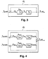
- FIG. 3 the signal flow diagram of such a position-controlled drive arrangement AT j with a single axis in the second axial direction j is shown in a highly simplified representation.
- the drive arrangement AT j is an NC position setpoint specification x j, soll specified by a numerical control unit, not illustrated.
- the drive A j moves to a position x j , is on.
- This position serves as a control variable x j, is for a position controller L j , the control error .DELTA.x j , ie the difference from controlled variable x j, is and setpoint x j , soll , is supplied as an input variable.
- the position controller L j determined from the control error Ax j a speed of the final drive A j as the control variable v j by the control error Ax j with a gain Kv is multiplied by j.
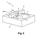
- FIG. 4 is the corresponding signal flow plan of a drive assembly AT i of the first axial direction i shown with two individual axes a and b, which interact without special measures.
- the position setpoint is here separately for a first and a second final drive A i, a, A i, b, ie, from a first target value x i, a soll, a first position x i, a is referred to as a control variable to form an as drag error Control error .DELTA.x i, a subtracted and to the drive A i, a associated controller L i, a supplied, which determines a manipulated variable v i, a for the drive A i, a by multiplication with a gain factor Kv i, a .
- a regulation of a second controlled variable x i, b is carried out correspondingly for the second drive A i, b .
- the two positions X i, a and X i, b is then superimposed to a total position x i, i is along the first axial direction.
- This object is achieved according to the invention by predetermining the control factor as a function of a gain specified for the first final drive and a gain specified for the second final drive, wherein the amplification factor specified for the second final drive represents an effective gain factor for the first drive arrangement and at least one additional, acting in a second axial direction
- the control factor represents an effective gain factor for the first drive arrangement and at least one additional, acting in a second axial direction
- the further drive arrangement is in this case constructed analogously to the drive arrangement acting in the first axial direction, ie, a variable proportional to the control error of the first final drive is supplied to the second final drive of this drive arrangement, which of the uniform for all axis directions, effective gain factor and the gain factor of the first in the second axis acting axle drive depends.
- Kv e is fixed then Kv i, a or Kv i, b can be determined from (*).
- Kv e is set by a numerical controller. If Kv e is to be variable as a function of the position along the trajectory, it must already be at the Path planning are defined, what happens in a path planning unit (see below). Due to the above-described specification of an identical effective gain Kv e along all axial directions, the drive arrangements act in the same way, regardless of how many axes the drive arrangements have. As a result, the aforementioned path distortions can be largely prevented, the design of the controlled NC axes does not matter, so that they can be performed in all known constructions, so for example as direct drives.
- the numerical control of the machine tool is assigned to specify the setpoint value, the control factor and the gain factors and possibly further variables, as a rule, a function module designated below as a path planning unit.
- the path planning unit is known all the relevant variables for the mobility of the individual axes and their control circuits (maximum values for achieving a desired accuracy). From the parts program that includes the workpiece geometry to be machined (alternatively, a taught path can be used as basis), it is determined and determined which motion components are to be output to the axial directions in such a way that optimizes the web movement in time and in terms of precision he follows.
- the path planning unit In the path planning unit, transformations (from space to machine axes and back) and interpolation algorithms for setting the desired position value to the individual axes are accomplished by known methods for the interaction of all machine axes.
- the path planning unit thus provides a parameter set for the optimized trajectory of the trajectory, which is used in the execution of the movement program of a numerical control unit for position control of the final drives.
- the web planning unit thus coordinates the drive arrangements acting in different directions before the trajectory of the trajectory.
- a second desired value for the second final drive is specified, wherein a division of a common setpoint for the first drive assembly in the first and second setpoint depending on the characteristics of the final drives and a predetermined trajectory for moving one through the drive assemblies moving tool and / or workpiece takes place.
- the path planning unit additionally makes the division of the movement in one axial direction into two or more individual axes.
- the kinematic ambiguities are resolved with respect to the resulting target positions, which are caused by the presence of the two or more axes in one axial direction. This is done by specifying the coupling of the individual axes (a, b) and by the precisely planned specification of the position setpoint values for the path to be traversed, taking into account and optimized tuning to the physical movement possibilities (limitations) of the individual axes.
- the common setpoint is divided into three or more setpoint components.
- the kinematically coupled individual axes which are connected in series one behind the other, are designed in such a way that they can individually approach and hold positions in the expected precision. So it is not a question of detecting design-related axis inaccuracies or workpiece deviations separately (using a separate sensor) and compensating with the coupled additional axis. Nevertheless, the method described can also be used advantageously for this task. In this case, for example, no own setpoint path is interpolated for the second individual axis, but its setpoint position is kept constant at zero. Thus, the second axis connected as additional axis acts as a leading axis purely for the reduction of the following error in order to reach Kv e . Of course, this can be done for one, several or all axial directions of the machine tool.
- the amount of the effective amplification factor is preferably predefined between an amplification factor optimized for the first final drive and an amplification factor optimized for the second final drive, wherein "between” is to be interpreted as meaning that the interval limits are included.
- the optimized amplification factors represent the maximum possible values which are determined according to the usual optimization criteria - without taking into account a coupling of the individual axes - which the path planning unit or the numerical control unit are known.
- the position of the axle drives is regulated, the speeds of the axle drives being set as manipulated variables.
- the speed and current of one (or all) drives can be specified by the controller directly as setpoints for the relevant controller.
- the associated position controller is thereby bypassed (possibly partially) and only acts for remaining deviations.
- first final drive On which an additional axis with a smaller travel path (second final drive) is constructed.
- first final drive is referred to as a slow final drive
- second final drive as a faster final drive
- the first axle drive is completely or partially pulse-decoupled from the second axle drive.
- a force is exerted on the other axle drive during the acceleration of one of the final drives, which force is compensated by the impulse decoupling. This can be done by an opposite movement of a mass provided for compensation taking into account the relative masses of the drives (so-called mass balance).
- the second axle drive for this purpose can also be attached via an elastic spring means or a damping means on the first axle drive, such as in the DE 198 10 996 A1 which is incorporated herein by reference in its entirety.
- the impulse decoupling Due to the impulse decoupling is the Motion of the second final drive with respect to the first axle drive, so that the well-known optimization criteria can be used without consideration of interfering effects to determine the control factors of the final drives. It is also possible to completely or partially dispense with the impulse decoupling if, based on the movements to be carried out, the individual axes are embodied in their disturbing behavior in such a way that the repercussions of the axes a and b give each other tolerable deviations.
- correction values for the supply to a current regulator and / or a rotational speed controller of the first and / or second final drive are generated from the mass and acceleration of the first final drive and / or the mass and acceleration of the second final drive.
- This variant is advantageous if no or partial impulse decoupling is carried out and the axes are too heavy and too sluggish, so that deviations occur that are no longer within the tolerance range.
- correction values are generated by the path planning unit or the numerical control unit from the accelerations a a and a b known from the interpolation and the masses of the axes (m a and m b ) which pre-control the current regulators, possibly also the speed controllers of the final drives be switched on each other.
- the effective amplification factor and / or the amplification factor prescribed for the first final drive is varied as a function of the position along the trajectory for the movement of a tool and / or workpiece moved by the drive arrangements along a predetermined trajectory.
- the gain factors are set as control parameters for a trajectory given by the parts program in advance in a numerical control and remain constant along the trajectory.
- the effective amplification factor is increased in path sections in which no movement occurs at least in one axial direction. If one (or more) axis directions are not involved in the movement, then these do not give rise to any path distortions.
- the slowest and / or the fastest axis drives of the drive arrangements of all axial directions of the machine tool have the same amplification factor for determining a manipulated variable from a controlled variable and preferably have identical frequency response.
- the individual axes (a, b) of all machine axis directions should be matched to one another. Such a coordination of all axes results automatically when the slowest and / or fastest axle drives are synchronized as described above.
- a desired value of the first and / or the second axle drive of at least the first drive arrangement is modified with a sensor control signal.
- the drive arrangement is associated with a sensor, which deviations of the current positioning, which is the basis of the programmed nominal path (ie, remaining deviations of the axes), determined by a desired path, such as a provided with surface deviations workpiece contour. Any "off-set" value is already included in the setpoint; according to z. B. the nominal distance nozzle plate in the distance control of a machine tool for laser machining of a workpiece.
- the invention is also realized in a web planning unit, comprising a computer program product for carrying out all steps of the method described above.
- the path planning unit will be given the machine tool characteristics (e.g., mechanical limitations of the final drives) and the part program, i. the trajectory to be generated, specified. From these data, the path planning unit determines a parameter set for the nominal values of the individual axes, the effective amplification factor, and the velocity gains of the individual axes.
- the parameter set can be stored by the web planning unit and subsequently retrieved by a numerical control unit, as soon as a predetermined trajectory with the machine tool is to be traced.
- the web planning unit can be integrated in the machine tool - in particular in a numerical control unit of the same or independent of this.
- a conventional computer can be used as a path planning unit if it is equipped with a suitable computer program product for carrying out the method.
- control unit is designed to specify a control factor for supplying the proportional variable as a function of a gain factor given to the first final drive and a gain factor specified for the second final drive, wherein the second Final drive specified Amplification factor forms an effective gain factor for the first drive assembly and at least one further, acting in a second axial direction drive unit.
- control unit is designed to specify a second setpoint value for the second final drive and the machine tool preferably has a path planning unit which is designed to divide a common setpoint for the first drive arrangement into the first and the second setpoint value as a function of the Properties of the final drives and a predetermined trajectory to move a moving through the drive assemblies tool and / or workpiece to make.
- the path planning thus defines which components of the movement in an axial direction the first or second final drive has to execute. This depends on the geometry of the workpiece to be machined and on the design-related limitations of the (all) individual interpolating machine axes. Limitations exist with respect to travel distances, speeds, accelerations and jerks as well as the position control factors; these are questions of interpretation.
- the motion components are output via the position command value specification (interpolation) to all axis drives.
- the axis drives are then separately controlled according to known position interpolation methods.
- the amount of the effective amplification factor is between an amplification factor optimized for the first final drive and an amplification factor optimized for the second final drive.
- the effective amplification factor is set by the path planning unit depending on the driving ability of the final drives between these two values.
- the controller error of the first axle drive is supplied to the second axle drive and the control factor is the difference between the effective gain factor and the gain specified by the first axle drive.
- control error of the first final drive is supplied to the controller of the second final drive, wherein the difference between the effective gain factor and the first gain factor is divided by the effective gain factor to form the control factor.
- the above-described formula (***) for the gain factor of the second final drive v i, b (Kv e - Kv i, a ) / Kv e ⁇ x i, a + ⁇ x i, b ) Kv e implemented by control technology.
- the controllers are position controllers for determining the speed setpoints of the final drives as manipulated variables. This corresponds to the typical application. In addition or as an alternative to the position control, it is also possible to carry out a speed control and / or a speed control in the manner described above.
- the second final drive is constructed on the first final drive. Movement in one axial direction can be realized by superimposing the movements of a slow basic axis with a large travel distance and a more dynamic additional axis with usually smaller travel distance.
- the machine tool can produce, for example for the X and Y directions, a series of small circle contours which are close to each other, exclusively from the dynamic individual axes , about Xb and Yb are executed.
- the process from circle to circle can be accomplished predominantly by less dynamic fundamental axes, Xa, Ya with a substantially constant, high traversing speed, and the dynamic auxiliary axes Xb, Yb drive the small circle contours high accelerations.
- the advantageous manner is carried out such that the corners for the less dynamic basic axes (Xa, Ya) are rounded (ie corresponding to their possibilities) larger, and the remaining corner contours are traversed by the dynamic additional axes (Xb, Yb).
- the division of the web movement depending on the part program is here, as already mentioned above, accomplished by the web planning unit.
- the bearing of the second final drive on the first final drive is completely or partially pulse-decoupled.
- Pulse decoupling can be achieved by mass balancing or suitable e.g. spring-mounted storage of the drives are produced.
- control unit is designed to generate correction values from the mass and acceleration of the first final drive and / or the mass and acceleration of the second final drive.
- machine tool has means for supplying the correction values to a current controller and / or a speed controller of the first and / or second axle drive. If no mechanical impulse decoupling is carried out or if the desired tolerances can not be achieved with this, the impulse decoupling can be carried out by means of a control by means of the correction values.
- the machine tool has a path planning unit which is designed to move the movement of a tool and / or workpiece moved by the drive arrangements along a predetermined trajectory the effective gain factor and / or the first gain of the first final drive depending on the position to change along the trajectory.
- the set of values passed on by the path planning unit to the numerical control unit serves to optimally optimize the control loop parameters of the final drives. This is particularly advantageous when it is not necessary to move through part of the trajectory in an axial direction which has the or a particularly sluggish drive arrangement.
- the effective gain factor which is otherwise limited by the inertia of this drive arrangement, can therefore be increased in this part of the trajectory.
- the slowest and / or fastest axis drives of all axial directions of the machine tool have a common amplification factor and preferably have identical frequency response.
- the machine tool has at least one sensor controller which modifies a setpoint variable of the first and / or the second final drive with a sensor control signal.
- the effectiveness (sharpness) of the sensor engagement can be predetermined via the factors Kp, Tn, Tv of the at least one sensor position controller, which can generally be embodied as a PID controller.
- Kp, Tn, Tv of the at least one sensor position controller which can generally be embodied as a PID controller.
- a single sensor controller is provided whose output signal modifies the setpoint values of all axle drives in an axial direction, or a separate sensor controller for one or a group of axle drives in one axial direction can be provided.
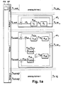
- Fig. 1a , b each show a signal flow plan of a position control of drive arrangements AT 1 to AT n of a machine tool, which are required for tracing a trajectory and act along axial directions 1,..., n.
- the number of drive arrangements n required for tracing a trajectory coincides with the total number of drive arrangements present on the machine tool.
- a first group of drive arrangements AT i each have a single final drive A j (cf. Fig. 3 ), a second group of drive arrangements AT i , two axle drives A i, a, A i, b (see FIG. Fig. 4 ) It is understood that in general more than two axle drives can act in one axial direction.
- the movement components predetermined in the path planning unit BP are output via the desired position value specification (interpolation) to all drive arrangements AT 1 to AT n .
- drive arrangements AT j with a single axis drive A j a single setpoint x j shall be predetermined, in drive arrangements AT i with two axis drives, the position setpoint to the individual axle drives A i, a , A i, b split, ie, a first final drive A.
- the trained as a servo drives drives A i, a , A i, b , A j are therefore separately controlled by known methods separately.
- the numerical control unit PM determines an effective amplification factor Kv e for all drive arrangements AT 1 to AT n . In the case of drive arrangements AT j, this is supplied to the associated controller L j for position control with only one final drive A j . In drive arrangements AT i with two axle drives A i, a , A i, b , the effective gain Kv e the controller L a of the second final drive A i, b supplied, which in the present case on the first final drive A i, a constructed and dynamic as this is.
- the value of the effective amplification factor Kv e in the axial direction i preferably lies between the maximum amplification factors (Kv values) Kv i, a or Kv i, b of the two final drives A i, a and A i, b in the latter Axial direction (cf. Fig. 4 ), which are determined according to the usual optimization criteria.
- Kv values maximum amplification factors
- the slowest of the drive arrangements AT 1 to AT n is used for this (possibly sectionally variable) uniform determination of the effective gain Kv e , since this acts limiting for all axis directions.
- path distortions due to differences in the following errors of different axial directions i, j can be substantially reduced.
- supply means that the proportional variable forms an input variable for the final drive or the controller, which as a rule is supplied together with other input variables at a summation point.
- Fig. 1a has the second controller for generating the manipulated variable v i, b for the second final drive A i, b a first control section L i, b (b) and a second, parallel control section L i, b (b) , wherein an input signal of the first Control section L i, b (b) is a control error Ax i, b of the second final drive A i, b and an input signal of the second control section L i, b (a) is a control error .DELTA.x i, a of the first final drive A i, a .
- the numerical control unit PM provides a control factor for the second control section L i, b (a) , which serves as a supply means for supplying the proportional amount to the second final drive A i , b, from the difference of the effective gain Kv e and the Amplification factor Kv i, a of the first final drive A i, b is formed, ie Kv e - Kv i, a .
- a regulator L i, b not divided into two control sections is used, to which a control factor, which in this case is formed by the difference between the effective amplification factor (Kv e ) and the first amplification factor (K), is given via a connection serving as a supply means.
- the control unit PM can keep the amplification factors constant during the entire execution of an NC program for tracing a trajectory. This applies in particular to the gain factor Kv i, a of the first final drive A i, a , if this is a less dynamic basic axis.
- the slowest of the drive arrangements AT 1 to AT n has a limiting effect for all axial directions 1 to n of the machine tool.
- the effective amplification factor Kv e is preferably carried out in track sections, in which one (or more) axial directions is uninvolved / are, so that this results in no path distortions.
- the gain factors Kv i, a of the first axle drives A i, a can also be changed as a function of the position along the trajectory.
- the gain factors Kv e can be increased without negative effects, so that the maximum mobility of the individual axle drives can be optimally utilized.
- the specification of the dynamic amplification factors is accomplished here in the path planning unit BP.
- the axle drives A i, a , A i, b, A j of all axial directions 1 to n can also be individually matched to one another.
- FIG Fig. 5 The procedure described above can be used in particular for the control of drive arrangements of a machine tool 1 , as shown schematically in FIG Fig. 5 is shown.
- a workpiece 3 is arranged there for processing by a tool 2 fixed on a table 4 .
- the tool 2 is movably mounted on a holding device 6 in the X-direction.
- the holding device 6 is in turn arranged movably in the Y-direction on a portal 5, which is movable even in the X direction.
- the holding device 6 has a lower mass than the portal 5 and the tool 2. Accordingly, movements in the X direction can be made faster by relative movement of the tool 2 to the holding device 6 than by movement of the portal 5.
- the portal 5 and the tool 2 are driven by a drive assembly AT i as in Fig.
- the first axle drive A i, a serves to move the gantry 5 on the table 4
- the second final drive A i, b serves to move the tool 2 along the holding device 6.
- the movement of the holding device 6 in the Y direction takes place in accordance with an axle drive A j a drive assembly AT j with only one final drive A j , as in Fig. 1 shown.
- a trajectory 7 planned in the path planning unit BP is thus traced as precisely and quickly as possible.
- the reaction of the one final drive A i, a to the other final drive A i, b must possibly be taken into account when designing the drive arrangement AT i .
- a mass balance can be performed, ie the portal 5 in Fig. 5 may have a mass (not shown) which performs a corresponding counter-movement in a jerky movement of the tool 2 in the X direction for compensation.
- the portal 5 can be mounted on the table 4 elastically resilient or damping to produce a pulse compensation.
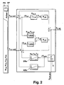
- a pulse compensation is not provided or is only partially carried out, it is possible, as in Fig. 2 for a drive arrangement AT i in the axial direction i, in the path planning unit BP the accelerations a i, a and a i, b known by the interpolation of the trajectory and the masses m i, a , m i, b of the axes (a and b) to use to generate correction values that are in Fig. 2 not graphically illustrated current regulators and possibly also speed regulators of the final drives A i, a and A i, b are connected to each other pilot-controlled.
- Fig. 2 shows for this purpose a sensor S , which deviations ⁇ x sen the position x i, is along the trajectory to be executed, which is based on the programmed nominal path (ie, remaining deviations of the axes) of a nominal path x soll, abs , about one provided with surface deviations Workpiece contour, determined. Any "off-set" value is already included in the current value x soll, abs of the nominal path; corresponding to approximately the nominal distance nozzle-plate in the distance control of a laser processing machine.
- the Deviation ⁇ x sen is fed to two sensor position controllers SR a , SR b , which are each assigned to one of the final drives A i, a , A i, b and generate a sensor control signal which is to add a respective desired value signal x i, a and x i, b becomes.
- the effectiveness (sharpness) of the sensor engagement can be specified via the factors Kp , Tn , Tv of the sensor position controllers SR a , SR b , which are in Fig. 2 are shown as PID controller. It is understood that a single sensor controller can be used which generates a sensor signal only for one final drive A i, a or A i, b or for both axle drives A i, a , A i, b together.
- the sensor S does not have to be a sensor aligned or active in the axial direction i, ie the positional deviation X soll determined by the sensor S , abs may also be a distributed, transformed component of a sensor signal, namely the case that the signal affects a plurality of axial directions i, that is, the sensor S is not fixed in an axial direction aligned (eg in a 3-D machining).
- identical amplification factors of the respective sensor drives SR a , SR b assigned to each final drive are to be used for all axis directions 1, or to transform the positional advance thereof in the case of just one sensor controller.
- the signal of a force sensor for example, for the Antikkraftregelung during grinding
- the (the) current controller of the Achsantriebe A i, a , A i, b can be switched on vor Kunststoffnd example, the (the) current controller of the Achsantriebe A i, a , A i, b .
- sensor signals can have strong noise components, which must be smoothed by low-pass filtering so that the excitation of the individual axis drives is not too high-frequency. The consideration of this fact is familiar to the skilled person.
Claims (25)
- Procédé pour coordonner des dispositifs d'entraînement (ATi, ATj) d'une machine-outil (1), qui agissent dans différentes directions axiales (i, j), englobant les étapes suivantes :préétablissement d'une première valeur de consigne (xi,a soll) pour un premier entraînement axial régulé (Ai,a) d'un premier dispositif d'entraînement (ATi) agissant dans une première direction axiale (i),préétablissement d'un facteur de régulation pour délivrer une grandeur, proportionnelle à une erreur de régulation (Δxi,a) du premier entraînement axial régulé (Ai,a), à au moins un second entraînement axial régulé (Ai,b) du premier dispositif d'entraînement (ATi),caractérisé parle préétablissement du facteur de régulation en fonction d'un facteur d'amplification (Kvi,a) préétabli pour le premier entraînement axial (Ai,a), et d'un facteur d'amplification (Kve) préétabli pour le second entraînement axial (Ai,b), sachant que le facteur d'amplification (Kve), préétabli pour le second entraînement axial (Ai,b), forme un facteur effectif d'amplification (Kve) pour le premier dispositif d'entraînement (ATi) et au moins un dispositif supplémentaire d'entraînement (ATj) agissant dans une seconde direction axiale (j).
- Procédé selon la revendication 1, caractérisé par le préétablissement d'une seconde valeur de consigne (xi,b soll) pour le second entraînement axial (A;,b), sachant qu'une subdivision d'une valeur commune de consigne (xi, soll) pour le premier dispositif d'entraînement (ATi), en les première et seconde valeurs de consigne (xi,a soll, xi,b soll), a lieu en fonction des propriétés des entraînements axiaux (Ai,a, Ai,b) et d'une courbe de trajectoire préétablie (7) en vue du mouvement d'un outil (2) et/ou d'une pièce (3) mis(e) en mouvement à travers les dispositifs d'entraînement (ATi, ATj).
- Procédé selon la revendication 1 ou 2, caractérisé par le fait que la valeur du facteur effectif d'amplification (Kve) est préétablie entre un facteur d'amplification (Kvi,a) optimalisé pour le premier entraînement axial (Ai,a), et un facteur d'amplification (Kvi,b) optimalisé pour le second entraînement axial (Ai,b).
- Procédé selon l'une des revendications précédentes, caractérisé par le fait que l'emplacement (xi, ist) des entraînements axiaux (Ai,a, Ai,b) est régulé, les vitesses (vi,a, vi,b) desdits entraînements axiaux (Ai,a, Ai,b) étant réglées en tant que grandeurs de réglage.
- Procédé selon l'une des revendications précédentes, caractérisé par le fait que le second entraînement axial (Ai,b) est implanté sur le premier entraînement axial (Ai,a) et est mis en mouvement conjointement à ce dernier.
- Procédé selon la revendication 5, caractérisé par le fait que le premier entraînement axial (Ai,a) est soumis à un découplage d'impulsions total ou partiel vis-à-vis du second entraînement (Ai,b).
- Procédé selon la revendication 5 ou 6, caractérisé par le fait que des valeurs correctrices, affectées à la délivrance à un régulateur de courant et/ou un régulateur de vitesse angulaire du premier et/ou du second entraînement axial (Ai,a, Ai,b), sont déterminées à partir de la masse (mi,a) et de l'accélération (ai,a) du premier entraînement axial (Ai,a), et/ou de la masse (mi,b) et de l'accélération (ai,b) du second entraînement axial (Ai,b).
- Procédé selon l'une des revendications précédentes, caractérisé par le fait que, en vue du mouvement, le long d'une courbe de trajectoire préétablie (7), d'un outil (2) et/ou d'une pièce (3) mis(e) en mouvement par les dispositifs d'entraînement (ATi, ATj), le facteur effectif d'amplification (Kve), et/ou le facteur d'amplification (Kvi,a) préétabli pour le premier entraînement axial (Ai,a), est (sont) modifié(s) en fonction de l'emplacement le long de ladite courbe de trajectoire (7).
- Procédé selon la revendication 8, caractérisé par le fait que le facteur effectif d'amplification (Kve) est augmenté sur des segments de trajectoire sur lesquels aucun mouvement ne s'opère, au moins dans une direction axiale.
- Procédé selon l'une des revendications précédentes, caractérisé par le fait qu'une grandeur de réglage Vi,a du premier entraînement axial (Ai,a), dans la première direction axiale (i), est établie comme suit :

et une grandeur de réglage vi,b du second entraînement axial (Ai,b) est établie comme suit :
sachant que Δxi,a, Δxi,b désignent les erreurs de régulation des premier et second entraînements axiaux (Ai,a, Ai,b) vis-à-vis des valeurs de consigne xi,a soll, xi,b soll ; que K vi,a est le facteur d'amplification du premier entraînement axial (Ai,a) du premier dispositif d'entraînement (ATi) dans la première direction axiale ; et que Kve désigne le facteur effectif d'amplification. - Procédé selon l'une des revendications précédentes, caractérisé par le fait que les entraînements axiaux les plus lents et/ou les entraînements axiaux les plus rapides (Ai,a, Aj,a) des dispositifs d'entraînement (ATi, ATj) de toutes les directions axiales (i, j) de la machine-outil (1) présentent le même facteur d'amplification (Kva) et offrent, de préférence, une allure de fréquence identique.
- Procédé selon l'une des revendications précédentes, caractérisé par le fait qu'une valeur de consigne (xi,a soll, xi,b soll) du premier et/ou du second entraînement axial (Ai,a, Ai,b) d'au moins le premier dispositif d'entraînement (ATi) est modifiée par un signal (SRa, SRb) de régulation de détection.
- Unité (BP) de planification de voie, comprenant un produit à programme d'ordinateur réalisé pour la mise en oeuvre de toutes les étapes du procédé selon l'une des revendications 1 à 12 lorsque le programme se déroule sur ladite unité (BP) de planification de voie.
- Machine-outil comprenant :un dispositif d'entraînement (ATi) agissant dans une première direction axiale (i) etcomportant un premier entraînement axial (Ai,a) à régulateur associé (Li,a) ; une unité de commande (PM) conçue pour la délivrance préalable d'une valeur de consigne (xi,a soll) audit régulateur (Li,a) dudit premier entraînement axial (Ai,a) ; ainsi que des moyens (Li,b(a)) pour délivrer une grandeur, proportionnelle à une erreur de régulation (Δxi,a) du premier entraînement axial (Ai,a), à au moins un second entraînement axial (Ai,b) du premier dispositif d'entraînement (ATi), ou à un régulateur (Li,b) associé audit second entraînement axial (Ai,b),caractérisée par le fait quel'unité de commande (PM) est réalisée pour préétablir un facteur de régulation, en vue de la délivrance de la grandeur proportionnelle en fonction d'un facteur d'amplification (Kvi,a) préétabli pour le premier entraînement axial (Ai,a), et d'un facteur d'amplification (Kve) préétabli pour le second entraînement axial (Ai,b), sachant que le facteur d'amplification (Kve), préétabli pour le second entraînement axial (Ai,b), forme un facteur effectif d'amplification (Kve) pour le premier dispositif d'entraînement (ATi) et au moins un dispositif supplémentaire d'entraînement (ATj) agissant dans une seconde direction axiale (j).
- Machine-outil selon la revendication 14, caractérisée par le fait que l'unité de commande (PM) est conçue pour la délivrance préalable d'une seconde valeur de consigne (xi,b soll) au second entraînement axial (Ai,b), ladite machine-outil étant de préférence munie d'une unité (BP) de planification de voie qui est prévue pour exécuter une subdivision d'une valeur commune de consigne (xi, soll) pour le premier dispositif d'entraînement (ATi), en les première et seconde valeurs de consigne (xi,a soll, xi,b soll), en fonction des propriétés des entraînements axiaux (Ai,a, Ai,b) et d'une courbe de trajectoire préétablie (7) en vue du mouvement d'un outil (2) et/ou d'une pièce (3) mis(e) en mouvement à travers les dispositifs d'entraînement (ATi, ATj).
- Machine-outil selon la revendication 14 ou 15, caractérisée par le fait que la valeur du facteur effectif d'amplification (Kve) se situe entre un facteur d'amplification (Kvi,a) optimalisé pour le premier entraînement axial (Ai,a), et un facteur d'amplification (Kvi,b) optimalisé pour le second entraînement axial (Ai,b).
- Machine-outil selon l'une des revendications 14 à 16, caractérisée par le fait que l'erreur de régulation (Δxi,a) du premier entraînement axial (Ai,a) est délivrée au second entraînement axial (Ai,b) ; et par le fait que le facteur de régulation (Kve- Kvi,a) est la différence entre le facteur effectif d'amplification (Kve) et le facteur d'amplification (Kvi,a) préétabli pour ledit premier entraînement axial (Ai,a).
- Machine-outil selon l'une des revendications 14 à 16, caractérisée par le fait que l'erreur de régulation (Δxi,a) du premier entraînement axial (Ai,a) est délivrée au régulateur (Li,b) du second entraînement axial (Ai,b) ; et par le fait que, en vue de former le facteur de régulation ((Kve - Kvi,a)/Kve), la différence entre le facteur effectif d'amplification (Kve), et le premier facteur d'amplification (Kvi,a), est divisée par ledit facteur d'amplification (Kve).
- Machine-outil selon l'une des revendications 14 à 18, caractérisée par le fait que les régulateurs (Li,a, Li,b) sont des régulateurs de position conçus pour établir, en tant que grandeurs de réglage (vi,a, vi,b), les valeurs de consigne de vitesse des entraînements axiaux (Ai,a, Ai,b).
- Machine-outil selon l'une des revendications 14 à 19, caractérisée par le fait que le second entraînement axial (Ai,b) est implanté sur le premier entraînement axial (Ai,a).
- Machine-outil selon la revendication 20, caractérisée par le fait que le système de montage du second entraînement axial (Ai,b), sur le premier entraînement axial (Ai,a), est réalisé avec découplage d'impulsions total ou partiel.
- Machine-outil selon la revendication 20 ou 21, caractérisée par le fait que l'unité de commande (PM) est conçue pour produire des valeurs correctrices à partir de la masse (mi,a) et de l'accélération (ai,a) du premier entraînement axial (Ai,a), et/ou de la masse (mi,b) et de l'accélération (ai,b) du second entraînement axial (Ai,b) ; et des moyens sont prévus pour délivrer lesdites valeurs correctrices à un régulateur de courant et/ou à un régulateur de vitesse angulaire du premier et/ou du second entraînement axial (Ai,a, Ai,b).
- Machine-outil selon l'une des revendications 14 ou 16 à 22, caractérisée par une unité (PM) de planification de voie qui est conçue pour modifier, en vue du mouvement d'un outil (2) et/ou d'une pièce (3) mis(e) en mouvement par les dispositifs d'entraînement (ATi, ATj) le long d'une courbe de trajectoire préétablie, le facteur effectif d'amplification (Kve) et/ou le premier facteur d'amplification (Kvi,a) du premier entraînement axial (Ai,a), en fonction de l'emplacement le long de ladite courbe de trajectoire (7).
- Machine-outil selon l'une des revendications 14 à 23, caractérisée par le fait que les entraînements axiaux les plus lents et/ou les entraînements axiaux les plus rapides (Ai,a, Ai,a) de toutes les directions axiales (i, j) de ladite machine-outil (1) présentent un facteur d'amplification commun (Kva) et possèdent, de préférence, une allure de fréquence identique.
- Machine-outil selon l'une des revendications 14 à 24, caractérisée par au moins un régulateur de détection (SRa, SRb) qui modifie une grandeur de consigne (xi,a soll, Xi,b soll) du premier et/ou du second entraînement axial (Ai,a, Ai,b) avec un signal de régulation de détection.
Applications Claiming Priority (1)
| Application Number | Priority Date | Filing Date | Title |
|---|---|---|---|
| PCT/EP2006/007607 WO2008014804A1 (fr) | 2006-08-01 | 2006-08-01 | Procédé pour coordonner des dispositifs d'entraînement d'une machine-outil, unité de planification de voie et machine-outil correspondante |
Publications (2)
| Publication Number | Publication Date |
|---|---|
| EP2016471A1 EP2016471A1 (fr) | 2009-01-21 |
| EP2016471B1 true EP2016471B1 (fr) | 2010-03-31 |
Family
ID=37847087
Family Applications (1)
| Application Number | Title | Priority Date | Filing Date |
|---|---|---|---|
| EP06762931A Active EP2016471B1 (fr) | 2006-08-01 | 2006-08-01 | Procédé pour coordonner des dispositifs d'entraînement d'une machine-outil, unité de planification de voie et machine-outil correspondante |
Country Status (4)
| Country | Link |
|---|---|
| EP (1) | EP2016471B1 (fr) |
| AT (1) | ATE462995T1 (fr) |
| DE (1) | DE502006006615D1 (fr) |
| WO (1) | WO2008014804A1 (fr) |
Families Citing this family (5)
| Publication number | Priority date | Publication date | Assignee | Title |
|---|---|---|---|---|
| DE102009039201B3 (de) * | 2009-08-27 | 2011-04-07 | Andreas Ehlerding | Einrichtung zur Kompensation von Beschleunigungskräften mittels Impulsentkopplung bei Mess- und Werkzeugmaschinen in mindestens einer translatorisch wirksamen Maschinenachse |
| JP5919346B2 (ja) * | 2014-09-01 | 2016-05-18 | ファナック株式会社 | 軸間干渉を補正するモータ制御装置 |
| EP3438773B1 (fr) * | 2017-08-04 | 2020-09-30 | Siemens Aktiengesellschaft | Usinage de pièces à compensation d'erreur basées sur modèles |
| DE102018109970B4 (de) | 2018-04-25 | 2021-09-02 | Carl Zeiss Industrielle Messtechnik Gmbh | Verfahren zur Steuerung eines Koordinatenmessgerätes sowie Koordinatenmessgerät |
| DE102019216972A1 (de) | 2019-11-04 | 2021-05-06 | Trumpf Laser- Und Systemtechnik Gmbh | Verfahren zum Erkennen von Ausschuss bei der Bearbeitung baugleicher Werkstücke sowie zugehörige numerisch gesteuerte Werkstückbearbeitungsvorrichtung |
Family Cites Families (3)
| Publication number | Priority date | Publication date | Assignee | Title |
|---|---|---|---|---|
| US4843293A (en) * | 1987-02-02 | 1989-06-27 | Research Development Corporation | Apparatus for controlling servo system employing piezo-electric actuator |
| JP2735153B2 (ja) * | 1995-03-03 | 1998-04-02 | 工業技術院長 | 精密位置制御装置及び精密位置制御方法 |
| DE502005004724D1 (de) * | 2005-02-04 | 2008-08-28 | Trumpf Werkzeugmaschinen Gmbh | Verfahren zur Bewegungsaufteilung einer Relativbewegung zwischen einem Werkstück und einem Werkzeug einer Werkzeugmaschine |
-
2006
- 2006-08-01 WO PCT/EP2006/007607 patent/WO2008014804A1/fr active Application Filing
- 2006-08-01 AT AT06762931T patent/ATE462995T1/de active
- 2006-08-01 EP EP06762931A patent/EP2016471B1/fr active Active
- 2006-08-01 DE DE502006006615T patent/DE502006006615D1/de active Active
Also Published As
| Publication number | Publication date |
|---|---|
| EP2016471A1 (fr) | 2009-01-21 |
| DE502006006615D1 (de) | 2010-05-12 |
| WO2008014804A1 (fr) | 2008-02-07 |
| ATE462995T1 (de) | 2010-04-15 |
Similar Documents
| Publication | Publication Date | Title |
|---|---|---|
| EP1688807B2 (fr) | Méthode pour la répartition du mouvement relatif entre une pièce et l'outil d'une machine outil | |
| EP1470458B1 (fr) | Procede de commande continue | |
| DE102009013388B4 (de) | Numerische Steuerungsvorrichtung und numerisches Steuerungsverfahren | |
| EP1934660B1 (fr) | Procede et dispositif pour guider le deplacement d'un element mobile d'une machine | |
| EP1963935B1 (fr) | Procede de determination d'une trajectoire approximative a suivre de maniere guidee en position | |
| EP2158526B1 (fr) | Procédé pour optimiser la coordination des mouvements de machines de mesure ou de machines-outils comportant des axes à translation redondante | |
| EP2156252B1 (fr) | Machine de mesure ou machine-outil à arbres redondants à action translatoire pour mouvement continu sur des trajectoires complexes | |
| WO2009000466A2 (fr) | Procédé destiné à optimiser la coordination de mouvements d'appareils de mesure ou de machines-outils au moyen d'axes de translation redondants | |
| DE102015011113B4 (de) | Motorsteuersystem, das eine Interferenz zwischen Achsen kompensiert | |
| DE3545795A1 (de) | Verfahren und vorrichtung fuer die numerische steuerung mit geschwindigkeitsdifferenz-verminderung | |
| DE102012101979B4 (de) | Verfahren und Vorrichtung zur Erzeugung einer Relativbewegung | |
| DE112012006074T5 (de) | Bahnregelungsvorrichtung | |
| EP2016471B1 (fr) | Procédé pour coordonner des dispositifs d'entraînement d'une machine-outil, unité de planification de voie et machine-outil correspondante | |
| EP3984686A1 (fr) | Méthode, unité de regulation et système de coupage laser pour la planification combinée des pistes et des processus laser pour systèmes en temps réel très dynamiques | |
| EP1421452B1 (fr) | Dispositif de production de grandeurs de reference pour des circuits de regulation d'une machine a commande numerique | |
| EP1977295B1 (fr) | Procédé de réglage d'axes | |
| EP0931283B1 (fr) | Procede et structure de regulation pour l'asservissement de couples de systemes multimasses, a commande numerique, elastiques et pouvant donc osciller | |
| EP4147102B1 (fr) | Fonctionnement d'une machine-outil au moins à deux axes | |
| DE3028312A1 (de) | Servosteuersystem | |
| EP3438773B1 (fr) | Usinage de pièces à compensation d'erreur basées sur modèles | |
| DE102005032336B4 (de) | Verfahren zur Beeinflussung einer Steuerung oder zur Steuerung einer Bewegungseinrichtung und Steuerung oder Steuerungskomponente einer Bewegungseinrichtung | |
| EP2623271B1 (fr) | Procédé destiné au fonctionnement d'une machine de traitement | |
| DE19637632A1 (de) | Numerisches Bahn-Steuersystem | |
| EP3335087A1 (fr) | Procédé de fourniture d'un profil de trajectoire, dispositif de commande, machine ainsi que programme d'ordinateur | |
| DE60104787T2 (de) | Verfahren und Vorrichtung zur Steuerung der Antriebmechanismen in NC-Werkzeugmachinen |
Legal Events
| Date | Code | Title | Description |
|---|---|---|---|
| PUAI | Public reference made under article 153(3) epc to a published international application that has entered the european phase |
Free format text: ORIGINAL CODE: 0009012 |
|
| 17P | Request for examination filed |
Effective date: 20081128 |
|
| AK | Designated contracting states |
Kind code of ref document: A1 Designated state(s): AT BE BG CH CY CZ DE DK EE ES FI FR GB GR HU IE IS IT LI LT LU LV MC NL PL PT RO SE SI SK TR |
|
| AX | Request for extension of the european patent |
Extension state: AL BA HR MK RS |
|
| 17Q | First examination report despatched |
Effective date: 20090316 |
|
| RIN1 | Information on inventor provided before grant (corrected) |
Inventor name: BOETTCHER, CHRISTIAN |
|
| GRAP | Despatch of communication of intention to grant a patent |
Free format text: ORIGINAL CODE: EPIDOSNIGR1 |
|
| DAX | Request for extension of the european patent (deleted) | ||
| GRAS | Grant fee paid |
Free format text: ORIGINAL CODE: EPIDOSNIGR3 |
|
| GRAA | (expected) grant |
Free format text: ORIGINAL CODE: 0009210 |
|
| AK | Designated contracting states |
Kind code of ref document: B1 Designated state(s): AT BE BG CH CY CZ DE DK EE ES FI FR GB GR HU IE IS IT LI LT LU LV MC NL PL PT RO SE SI SK TR |
|
| REG | Reference to a national code |
Ref country code: GB Ref legal event code: FG4D Free format text: NOT ENGLISH Ref country code: CH Ref legal event code: EP |
|
| REG | Reference to a national code |
Ref country code: IE Ref legal event code: FG4D |
|
| REF | Corresponds to: |
Ref document number: 502006006615 Country of ref document: DE Date of ref document: 20100512 Kind code of ref document: P |
|
| REG | Reference to a national code |
Ref country code: NL Ref legal event code: VDEP Effective date: 20100331 |
|
| PG25 | Lapsed in a contracting state [announced via postgrant information from national office to epo] |
Ref country code: LT Free format text: LAPSE BECAUSE OF FAILURE TO SUBMIT A TRANSLATION OF THE DESCRIPTION OR TO PAY THE FEE WITHIN THE PRESCRIBED TIME-LIMIT Effective date: 20100331 |
|
| LTIE | Lt: invalidation of european patent or patent extension |
Effective date: 20100331 |
|
| PG25 | Lapsed in a contracting state [announced via postgrant information from national office to epo] |
Ref country code: SI Free format text: LAPSE BECAUSE OF FAILURE TO SUBMIT A TRANSLATION OF THE DESCRIPTION OR TO PAY THE FEE WITHIN THE PRESCRIBED TIME-LIMIT Effective date: 20100331 Ref country code: PL Free format text: LAPSE BECAUSE OF FAILURE TO SUBMIT A TRANSLATION OF THE DESCRIPTION OR TO PAY THE FEE WITHIN THE PRESCRIBED TIME-LIMIT Effective date: 20100331 Ref country code: LV Free format text: LAPSE BECAUSE OF FAILURE TO SUBMIT A TRANSLATION OF THE DESCRIPTION OR TO PAY THE FEE WITHIN THE PRESCRIBED TIME-LIMIT Effective date: 20100331 Ref country code: FI Free format text: LAPSE BECAUSE OF FAILURE TO SUBMIT A TRANSLATION OF THE DESCRIPTION OR TO PAY THE FEE WITHIN THE PRESCRIBED TIME-LIMIT Effective date: 20100331 |
|
| REG | Reference to a national code |
Ref country code: IE Ref legal event code: FD4D |
|
| PG25 | Lapsed in a contracting state [announced via postgrant information from national office to epo] |
Ref country code: RO Free format text: LAPSE BECAUSE OF FAILURE TO SUBMIT A TRANSLATION OF THE DESCRIPTION OR TO PAY THE FEE WITHIN THE PRESCRIBED TIME-LIMIT Effective date: 20100331 Ref country code: ES Free format text: LAPSE BECAUSE OF FAILURE TO SUBMIT A TRANSLATION OF THE DESCRIPTION OR TO PAY THE FEE WITHIN THE PRESCRIBED TIME-LIMIT Effective date: 20100712 Ref country code: SE Free format text: LAPSE BECAUSE OF FAILURE TO SUBMIT A TRANSLATION OF THE DESCRIPTION OR TO PAY THE FEE WITHIN THE PRESCRIBED TIME-LIMIT Effective date: 20100331 Ref country code: NL Free format text: LAPSE BECAUSE OF FAILURE TO SUBMIT A TRANSLATION OF THE DESCRIPTION OR TO PAY THE FEE WITHIN THE PRESCRIBED TIME-LIMIT Effective date: 20100331 Ref country code: EE Free format text: LAPSE BECAUSE OF FAILURE TO SUBMIT A TRANSLATION OF THE DESCRIPTION OR TO PAY THE FEE WITHIN THE PRESCRIBED TIME-LIMIT Effective date: 20100331 Ref country code: CY Free format text: LAPSE BECAUSE OF FAILURE TO SUBMIT A TRANSLATION OF THE DESCRIPTION OR TO PAY THE FEE WITHIN THE PRESCRIBED TIME-LIMIT Effective date: 20100331 |
|
| PG25 | Lapsed in a contracting state [announced via postgrant information from national office to epo] |
Ref country code: CZ Free format text: LAPSE BECAUSE OF FAILURE TO SUBMIT A TRANSLATION OF THE DESCRIPTION OR TO PAY THE FEE WITHIN THE PRESCRIBED TIME-LIMIT Effective date: 20100331 Ref country code: IS Free format text: LAPSE BECAUSE OF FAILURE TO SUBMIT A TRANSLATION OF THE DESCRIPTION OR TO PAY THE FEE WITHIN THE PRESCRIBED TIME-LIMIT Effective date: 20100731 Ref country code: SK Free format text: LAPSE BECAUSE OF FAILURE TO SUBMIT A TRANSLATION OF THE DESCRIPTION OR TO PAY THE FEE WITHIN THE PRESCRIBED TIME-LIMIT Effective date: 20100331 |
|
| PG25 | Lapsed in a contracting state [announced via postgrant information from national office to epo] |
Ref country code: PT Free format text: LAPSE BECAUSE OF FAILURE TO SUBMIT A TRANSLATION OF THE DESCRIPTION OR TO PAY THE FEE WITHIN THE PRESCRIBED TIME-LIMIT Effective date: 20100802 Ref country code: DK Free format text: LAPSE BECAUSE OF FAILURE TO SUBMIT A TRANSLATION OF THE DESCRIPTION OR TO PAY THE FEE WITHIN THE PRESCRIBED TIME-LIMIT Effective date: 20100331 Ref country code: IE Free format text: LAPSE BECAUSE OF FAILURE TO SUBMIT A TRANSLATION OF THE DESCRIPTION OR TO PAY THE FEE WITHIN THE PRESCRIBED TIME-LIMIT Effective date: 20100331 |
|
| PLBE | No opposition filed within time limit |
Free format text: ORIGINAL CODE: 0009261 |
|
| STAA | Information on the status of an ep patent application or granted ep patent |
Free format text: STATUS: NO OPPOSITION FILED WITHIN TIME LIMIT |
|
| BERE | Be: lapsed |
Owner name: TRUMPF WERKZEUGMASCHINEN G.M.B.H. + CO. KG Effective date: 20100831 |
|
| 26N | No opposition filed |
Effective date: 20110104 |
|
| PG25 | Lapsed in a contracting state [announced via postgrant information from national office to epo] |
Ref country code: MC Free format text: LAPSE BECAUSE OF NON-PAYMENT OF DUE FEES Effective date: 20100831 |
|
| REG | Reference to a national code |
Ref country code: CH Ref legal event code: PL |
|
| GBPC | Gb: european patent ceased through non-payment of renewal fee |
Effective date: 20100801 |
|
| PG25 | Lapsed in a contracting state [announced via postgrant information from national office to epo] |
Ref country code: LI Free format text: LAPSE BECAUSE OF NON-PAYMENT OF DUE FEES Effective date: 20100831 Ref country code: CH Free format text: LAPSE BECAUSE OF NON-PAYMENT OF DUE FEES Effective date: 20100831 |
|
| REG | Reference to a national code |
Ref country code: FR Ref legal event code: ST Effective date: 20110502 |
|
| PG25 | Lapsed in a contracting state [announced via postgrant information from national office to epo] |
Ref country code: FR Free format text: LAPSE BECAUSE OF NON-PAYMENT OF DUE FEES Effective date: 20100831 Ref country code: BE Free format text: LAPSE BECAUSE OF NON-PAYMENT OF DUE FEES Effective date: 20100831 |
|
| PG25 | Lapsed in a contracting state [announced via postgrant information from national office to epo] |
Ref country code: GB Free format text: LAPSE BECAUSE OF NON-PAYMENT OF DUE FEES Effective date: 20100801 |
|
| PG25 | Lapsed in a contracting state [announced via postgrant information from national office to epo] |
Ref country code: BG Free format text: LAPSE BECAUSE OF FAILURE TO SUBMIT A TRANSLATION OF THE DESCRIPTION OR TO PAY THE FEE WITHIN THE PRESCRIBED TIME-LIMIT Effective date: 20100331 Ref country code: HU Free format text: LAPSE BECAUSE OF FAILURE TO SUBMIT A TRANSLATION OF THE DESCRIPTION OR TO PAY THE FEE WITHIN THE PRESCRIBED TIME-LIMIT Effective date: 20101001 Ref country code: LU Free format text: LAPSE BECAUSE OF NON-PAYMENT OF DUE FEES Effective date: 20100801 |
|
| PG25 | Lapsed in a contracting state [announced via postgrant information from national office to epo] |
Ref country code: TR Free format text: LAPSE BECAUSE OF FAILURE TO SUBMIT A TRANSLATION OF THE DESCRIPTION OR TO PAY THE FEE WITHIN THE PRESCRIBED TIME-LIMIT Effective date: 20100331 |
|
| REG | Reference to a national code |
Ref country code: AT Ref legal event code: MM01 Ref document number: 462995 Country of ref document: AT Kind code of ref document: T Effective date: 20110801 |
|
| PG25 | Lapsed in a contracting state [announced via postgrant information from national office to epo] |
Ref country code: AT Free format text: LAPSE BECAUSE OF NON-PAYMENT OF DUE FEES Effective date: 20110801 |
|
| PG25 | Lapsed in a contracting state [announced via postgrant information from national office to epo] |
Ref country code: BG Free format text: LAPSE BECAUSE OF FAILURE TO SUBMIT A TRANSLATION OF THE DESCRIPTION OR TO PAY THE FEE WITHIN THE PRESCRIBED TIME-LIMIT Effective date: 20100630 |
|
| PG25 | Lapsed in a contracting state [announced via postgrant information from national office to epo] |
Ref country code: GR Free format text: LAPSE BECAUSE OF FAILURE TO SUBMIT A TRANSLATION OF THE DESCRIPTION OR TO PAY THE FEE WITHIN THE PRESCRIBED TIME-LIMIT Effective date: 20100331 |
|
| PGFP | Annual fee paid to national office [announced via postgrant information from national office to epo] |
Ref country code: IT Payment date: 20230825 Year of fee payment: 18 |
|
| PGFP | Annual fee paid to national office [announced via postgrant information from national office to epo] |
Ref country code: DE Payment date: 20230821 Year of fee payment: 18 |