EP2954942B1 - Dispositif de collecte de dioxyde de carbone - Google Patents
Dispositif de collecte de dioxyde de carbone Download PDFInfo
- Publication number
- EP2954942B1 EP2954942B1 EP14762615.4A EP14762615A EP2954942B1 EP 2954942 B1 EP2954942 B1 EP 2954942B1 EP 14762615 A EP14762615 A EP 14762615A EP 2954942 B1 EP2954942 B1 EP 2954942B1
- Authority
- EP
- European Patent Office
- Prior art keywords
- carbon dioxide
- desorption
- adsorption
- heat exchange
- column
- Prior art date
- Legal status (The legal status is an assumption and is not a legal conclusion. Google has not performed a legal analysis and makes no representation as to the accuracy of the status listed.)
- Active
Links
- CURLTUGMZLYLDI-UHFFFAOYSA-N Carbon dioxide Chemical compound O=C=O CURLTUGMZLYLDI-UHFFFAOYSA-N 0.000 title claims description 932
- 229910002092 carbon dioxide Inorganic materials 0.000 title claims description 469
- 239000001569 carbon dioxide Substances 0.000 title claims description 458
- 238000001179 sorption measurement Methods 0.000 claims description 231
- 238000003795 desorption Methods 0.000 claims description 192
- 239000003463 adsorbent Substances 0.000 claims description 43
- 239000003546 flue gas Substances 0.000 claims description 32
- 230000005587 bubbling Effects 0.000 claims description 23
- 238000000926 separation method Methods 0.000 claims description 9
- 239000002250 absorbent Substances 0.000 description 196
- 230000002745 absorbent Effects 0.000 description 196
- 238000000034 method Methods 0.000 description 45
- 230000008569 process Effects 0.000 description 27
- 238000002336 sorption--desorption measurement Methods 0.000 description 18
- 238000011144 upstream manufacturing Methods 0.000 description 18
- UGFAIRIUMAVXCW-UHFFFAOYSA-N Carbon monoxide Chemical compound [O+]#[C-] UGFAIRIUMAVXCW-UHFFFAOYSA-N 0.000 description 16
- 238000010276 construction Methods 0.000 description 13
- 239000007790 solid phase Substances 0.000 description 13
- 230000001965 increasing effect Effects 0.000 description 8
- 238000005191 phase separation Methods 0.000 description 8
- OKTJSMMVPCPJKN-UHFFFAOYSA-N Carbon Chemical compound [C] OKTJSMMVPCPJKN-UHFFFAOYSA-N 0.000 description 7
- 238000002485 combustion reaction Methods 0.000 description 7
- 229910052799 carbon Inorganic materials 0.000 description 5
- 239000002594 sorbent Substances 0.000 description 5
- 239000003054 catalyst Substances 0.000 description 4
- 230000008929 regeneration Effects 0.000 description 4
- 238000011069 regeneration method Methods 0.000 description 4
- 238000010521 absorption reaction Methods 0.000 description 3
- 229910052784 alkaline earth metal Inorganic materials 0.000 description 3
- 238000004523 catalytic cracking Methods 0.000 description 3
- 230000000694 effects Effects 0.000 description 3
- 238000005265 energy consumption Methods 0.000 description 3
- 238000010438 heat treatment Methods 0.000 description 3
- 239000012528 membrane Substances 0.000 description 3
- 238000012546 transfer Methods 0.000 description 3
- VYPSYNLAJGMNEJ-UHFFFAOYSA-N Silicium dioxide Chemical compound O=[Si]=O VYPSYNLAJGMNEJ-UHFFFAOYSA-N 0.000 description 2
- 229910000831 Steel Inorganic materials 0.000 description 2
- 229910021536 Zeolite Inorganic materials 0.000 description 2
- 239000003513 alkali Substances 0.000 description 2
- 150000001342 alkaline earth metals Chemical class 0.000 description 2
- 150000001412 amines Chemical class 0.000 description 2
- 230000008901 benefit Effects 0.000 description 2
- 238000001816 cooling Methods 0.000 description 2
- 238000011161 development Methods 0.000 description 2
- 230000018109 developmental process Effects 0.000 description 2
- 238000010586 diagram Methods 0.000 description 2
- HNPSIPDUKPIQMN-UHFFFAOYSA-N dioxosilane;oxo(oxoalumanyloxy)alumane Chemical compound O=[Si]=O.O=[Al]O[Al]=O HNPSIPDUKPIQMN-UHFFFAOYSA-N 0.000 description 2
- 239000012530 fluid Substances 0.000 description 2
- 239000002803 fossil fuel Substances 0.000 description 2
- 239000007789 gas Substances 0.000 description 2
- 239000007791 liquid phase Substances 0.000 description 2
- 238000012545 processing Methods 0.000 description 2
- 230000009467 reduction Effects 0.000 description 2
- 239000007787 solid Substances 0.000 description 2
- 239000010959 steel Substances 0.000 description 2
- 238000003860 storage Methods 0.000 description 2
- 238000010792 warming Methods 0.000 description 2
- 239000010457 zeolite Substances 0.000 description 2
- VHUUQVKOLVNVRT-UHFFFAOYSA-N Ammonium hydroxide Chemical compound [NH4+].[OH-] VHUUQVKOLVNVRT-UHFFFAOYSA-N 0.000 description 1
- UCKMPCXJQFINFW-UHFFFAOYSA-N Sulphide Chemical compound [S-2] UCKMPCXJQFINFW-UHFFFAOYSA-N 0.000 description 1
- 229910052783 alkali metal Inorganic materials 0.000 description 1
- 150000001340 alkali metals Chemical group 0.000 description 1
- 125000003277 amino group Chemical group 0.000 description 1
- QGZKDVFQNNGYKY-UHFFFAOYSA-N ammonia Natural products N QGZKDVFQNNGYKY-UHFFFAOYSA-N 0.000 description 1
- 238000006243 chemical reaction Methods 0.000 description 1
- 239000012141 concentrate Substances 0.000 description 1
- 239000000470 constituent Substances 0.000 description 1
- 238000006477 desulfuration reaction Methods 0.000 description 1
- 238000005516 engineering process Methods 0.000 description 1
- 238000005243 fluidization Methods 0.000 description 1
- 239000000446 fuel Substances 0.000 description 1
- 239000005431 greenhouse gas Substances 0.000 description 1
- 230000006872 improvement Effects 0.000 description 1
- 230000001939 inductive effect Effects 0.000 description 1
- 239000007788 liquid Substances 0.000 description 1
- 239000000463 material Substances 0.000 description 1
- 230000007246 mechanism Effects 0.000 description 1
- 238000002844 melting Methods 0.000 description 1
- 230000008018 melting Effects 0.000 description 1
- 238000012986 modification Methods 0.000 description 1
- 230000004048 modification Effects 0.000 description 1
- 150000004767 nitrides Chemical class 0.000 description 1
- 239000011368 organic material Substances 0.000 description 1
- 230000037361 pathway Effects 0.000 description 1
- JTJMJGYZQZDUJJ-UHFFFAOYSA-N phencyclidine Chemical class C1CCCCN1C1(C=2C=CC=CC=2)CCCCC1 JTJMJGYZQZDUJJ-UHFFFAOYSA-N 0.000 description 1
- 229920000642 polymer Polymers 0.000 description 1
- 230000007420 reactivation Effects 0.000 description 1
- 238000004064 recycling Methods 0.000 description 1
- 238000013341 scale-up Methods 0.000 description 1
- 239000000377 silicon dioxide Substances 0.000 description 1
- 239000002689 soil Substances 0.000 description 1
- 239000000126 substance Substances 0.000 description 1
- XLYOFNOQVPJJNP-UHFFFAOYSA-N water Substances O XLYOFNOQVPJJNP-UHFFFAOYSA-N 0.000 description 1
Images


Classifications
-
- B—PERFORMING OPERATIONS; TRANSPORTING
- B01—PHYSICAL OR CHEMICAL PROCESSES OR APPARATUS IN GENERAL
- B01D—SEPARATION
- B01D53/00—Separation of gases or vapours; Recovering vapours of volatile solvents from gases; Chemical or biological purification of waste gases, e.g. engine exhaust gases, smoke, fumes, flue gases, aerosols
- B01D53/02—Separation of gases or vapours; Recovering vapours of volatile solvents from gases; Chemical or biological purification of waste gases, e.g. engine exhaust gases, smoke, fumes, flue gases, aerosols by adsorption, e.g. preparative gas chromatography
- B01D53/04—Separation of gases or vapours; Recovering vapours of volatile solvents from gases; Chemical or biological purification of waste gases, e.g. engine exhaust gases, smoke, fumes, flue gases, aerosols by adsorption, e.g. preparative gas chromatography with stationary adsorbents
- B01D53/047—Pressure swing adsorption
-
- B—PERFORMING OPERATIONS; TRANSPORTING
- B01—PHYSICAL OR CHEMICAL PROCESSES OR APPARATUS IN GENERAL
- B01D—SEPARATION
- B01D53/00—Separation of gases or vapours; Recovering vapours of volatile solvents from gases; Chemical or biological purification of waste gases, e.g. engine exhaust gases, smoke, fumes, flue gases, aerosols
- B01D53/02—Separation of gases or vapours; Recovering vapours of volatile solvents from gases; Chemical or biological purification of waste gases, e.g. engine exhaust gases, smoke, fumes, flue gases, aerosols by adsorption, e.g. preparative gas chromatography
- B01D53/04—Separation of gases or vapours; Recovering vapours of volatile solvents from gases; Chemical or biological purification of waste gases, e.g. engine exhaust gases, smoke, fumes, flue gases, aerosols by adsorption, e.g. preparative gas chromatography with stationary adsorbents
- B01D53/0462—Temperature swing adsorption
-
- B—PERFORMING OPERATIONS; TRANSPORTING
- B01—PHYSICAL OR CHEMICAL PROCESSES OR APPARATUS IN GENERAL
- B01D—SEPARATION
- B01D53/00—Separation of gases or vapours; Recovering vapours of volatile solvents from gases; Chemical or biological purification of waste gases, e.g. engine exhaust gases, smoke, fumes, flue gases, aerosols
- B01D53/02—Separation of gases or vapours; Recovering vapours of volatile solvents from gases; Chemical or biological purification of waste gases, e.g. engine exhaust gases, smoke, fumes, flue gases, aerosols by adsorption, e.g. preparative gas chromatography
- B01D53/04—Separation of gases or vapours; Recovering vapours of volatile solvents from gases; Chemical or biological purification of waste gases, e.g. engine exhaust gases, smoke, fumes, flue gases, aerosols by adsorption, e.g. preparative gas chromatography with stationary adsorbents
-
- B—PERFORMING OPERATIONS; TRANSPORTING
- B01—PHYSICAL OR CHEMICAL PROCESSES OR APPARATUS IN GENERAL
- B01D—SEPARATION
- B01D53/00—Separation of gases or vapours; Recovering vapours of volatile solvents from gases; Chemical or biological purification of waste gases, e.g. engine exhaust gases, smoke, fumes, flue gases, aerosols
- B01D53/02—Separation of gases or vapours; Recovering vapours of volatile solvents from gases; Chemical or biological purification of waste gases, e.g. engine exhaust gases, smoke, fumes, flue gases, aerosols by adsorption, e.g. preparative gas chromatography
- B01D53/06—Separation of gases or vapours; Recovering vapours of volatile solvents from gases; Chemical or biological purification of waste gases, e.g. engine exhaust gases, smoke, fumes, flue gases, aerosols by adsorption, e.g. preparative gas chromatography with moving adsorbents, e.g. rotating beds
- B01D53/08—Separation of gases or vapours; Recovering vapours of volatile solvents from gases; Chemical or biological purification of waste gases, e.g. engine exhaust gases, smoke, fumes, flue gases, aerosols by adsorption, e.g. preparative gas chromatography with moving adsorbents, e.g. rotating beds according to the "moving bed" method
-
- B—PERFORMING OPERATIONS; TRANSPORTING
- B01—PHYSICAL OR CHEMICAL PROCESSES OR APPARATUS IN GENERAL
- B01D—SEPARATION
- B01D53/00—Separation of gases or vapours; Recovering vapours of volatile solvents from gases; Chemical or biological purification of waste gases, e.g. engine exhaust gases, smoke, fumes, flue gases, aerosols
- B01D53/02—Separation of gases or vapours; Recovering vapours of volatile solvents from gases; Chemical or biological purification of waste gases, e.g. engine exhaust gases, smoke, fumes, flue gases, aerosols by adsorption, e.g. preparative gas chromatography
- B01D53/06—Separation of gases or vapours; Recovering vapours of volatile solvents from gases; Chemical or biological purification of waste gases, e.g. engine exhaust gases, smoke, fumes, flue gases, aerosols by adsorption, e.g. preparative gas chromatography with moving adsorbents, e.g. rotating beds
- B01D53/10—Separation of gases or vapours; Recovering vapours of volatile solvents from gases; Chemical or biological purification of waste gases, e.g. engine exhaust gases, smoke, fumes, flue gases, aerosols by adsorption, e.g. preparative gas chromatography with moving adsorbents, e.g. rotating beds with dispersed adsorbents
- B01D53/12—Separation of gases or vapours; Recovering vapours of volatile solvents from gases; Chemical or biological purification of waste gases, e.g. engine exhaust gases, smoke, fumes, flue gases, aerosols by adsorption, e.g. preparative gas chromatography with moving adsorbents, e.g. rotating beds with dispersed adsorbents according to the "fluidised technique"
-
- B—PERFORMING OPERATIONS; TRANSPORTING
- B01—PHYSICAL OR CHEMICAL PROCESSES OR APPARATUS IN GENERAL
- B01D—SEPARATION
- B01D53/00—Separation of gases or vapours; Recovering vapours of volatile solvents from gases; Chemical or biological purification of waste gases, e.g. engine exhaust gases, smoke, fumes, flue gases, aerosols
- B01D53/34—Chemical or biological purification of waste gases
- B01D53/46—Removing components of defined structure
- B01D53/62—Carbon oxides
-
- B—PERFORMING OPERATIONS; TRANSPORTING
- B01—PHYSICAL OR CHEMICAL PROCESSES OR APPARATUS IN GENERAL
- B01J—CHEMICAL OR PHYSICAL PROCESSES, e.g. CATALYSIS OR COLLOID CHEMISTRY; THEIR RELEVANT APPARATUS
- B01J8/00—Chemical or physical processes in general, conducted in the presence of fluids and solid particles; Apparatus for such processes
-
- B—PERFORMING OPERATIONS; TRANSPORTING
- B01—PHYSICAL OR CHEMICAL PROCESSES OR APPARATUS IN GENERAL
- B01D—SEPARATION
- B01D2251/00—Reactants
- B01D2251/30—Alkali metal compounds
-
- B—PERFORMING OPERATIONS; TRANSPORTING
- B01—PHYSICAL OR CHEMICAL PROCESSES OR APPARATUS IN GENERAL
- B01D—SEPARATION
- B01D2251/00—Reactants
- B01D2251/40—Alkaline earth metal or magnesium compounds
-
- B—PERFORMING OPERATIONS; TRANSPORTING
- B01—PHYSICAL OR CHEMICAL PROCESSES OR APPARATUS IN GENERAL
- B01D—SEPARATION
- B01D2253/00—Adsorbents used in seperation treatment of gases and vapours
- B01D2253/10—Inorganic adsorbents
- B01D2253/102—Carbon
-
- B—PERFORMING OPERATIONS; TRANSPORTING
- B01—PHYSICAL OR CHEMICAL PROCESSES OR APPARATUS IN GENERAL
- B01D—SEPARATION
- B01D2253/00—Adsorbents used in seperation treatment of gases and vapours
- B01D2253/10—Inorganic adsorbents
- B01D2253/106—Silica or silicates
-
- B—PERFORMING OPERATIONS; TRANSPORTING
- B01—PHYSICAL OR CHEMICAL PROCESSES OR APPARATUS IN GENERAL
- B01D—SEPARATION
- B01D2253/00—Adsorbents used in seperation treatment of gases and vapours
- B01D2253/10—Inorganic adsorbents
- B01D2253/106—Silica or silicates
- B01D2253/108—Zeolites
-
- B—PERFORMING OPERATIONS; TRANSPORTING
- B01—PHYSICAL OR CHEMICAL PROCESSES OR APPARATUS IN GENERAL
- B01D—SEPARATION
- B01D2253/00—Adsorbents used in seperation treatment of gases and vapours
- B01D2253/20—Organic adsorbents
- B01D2253/204—Metal organic frameworks (MOF's)
-
- B—PERFORMING OPERATIONS; TRANSPORTING
- B01—PHYSICAL OR CHEMICAL PROCESSES OR APPARATUS IN GENERAL
- B01D—SEPARATION
- B01D2257/00—Components to be removed
- B01D2257/50—Carbon oxides
- B01D2257/504—Carbon dioxide
-
- B—PERFORMING OPERATIONS; TRANSPORTING
- B01—PHYSICAL OR CHEMICAL PROCESSES OR APPARATUS IN GENERAL
- B01D—SEPARATION
- B01D2258/00—Sources of waste gases
- B01D2258/02—Other waste gases
- B01D2258/025—Other waste gases from metallurgy plants
-
- B—PERFORMING OPERATIONS; TRANSPORTING
- B01—PHYSICAL OR CHEMICAL PROCESSES OR APPARATUS IN GENERAL
- B01D—SEPARATION
- B01D2258/00—Sources of waste gases
- B01D2258/02—Other waste gases
- B01D2258/0283—Flue gases
-
- B—PERFORMING OPERATIONS; TRANSPORTING
- B01—PHYSICAL OR CHEMICAL PROCESSES OR APPARATUS IN GENERAL
- B01D—SEPARATION
- B01D2259/00—Type of treatment
- B01D2259/40—Further details for adsorption processes and devices
- B01D2259/40083—Regeneration of adsorbents in processes other than pressure or temperature swing adsorption
- B01D2259/40088—Regeneration of adsorbents in processes other than pressure or temperature swing adsorption by heating
- B01D2259/40098—Regeneration of adsorbents in processes other than pressure or temperature swing adsorption by heating with other heating means
-
- Y—GENERAL TAGGING OF NEW TECHNOLOGICAL DEVELOPMENTS; GENERAL TAGGING OF CROSS-SECTIONAL TECHNOLOGIES SPANNING OVER SEVERAL SECTIONS OF THE IPC; TECHNICAL SUBJECTS COVERED BY FORMER USPC CROSS-REFERENCE ART COLLECTIONS [XRACs] AND DIGESTS
- Y02—TECHNOLOGIES OR APPLICATIONS FOR MITIGATION OR ADAPTATION AGAINST CLIMATE CHANGE
- Y02C—CAPTURE, STORAGE, SEQUESTRATION OR DISPOSAL OF GREENHOUSE GASES [GHG]
- Y02C20/00—Capture or disposal of greenhouse gases
- Y02C20/40—Capture or disposal of greenhouse gases of CO2
Definitions
- the present invention relates to a carbon dioxide capture apparatus, and more specifically to a carbon dioxide capture apparatus that prevents carbon dioxide present in flue gases from industrial facilities responsible for large emissions of carbon dioxide, such as power plants and steel mills, from being exhausted into the atmosphere.
- CCS carbon capture and storage
- Document US 2009/120288 discloses a carbon dioxide capture method that comprises a sorbent material 30 which captures CO2 within a gas stream.
- the sorbent material 30 can then be moved from a capture unit 10 wherein it captured the CO2 to a regeneration unit 20 where the CO2 is released.
- a heat exchanger 40 is used to transfer heat from the regeneration unit 20 to the CO2-loaded sorbent material 30. Accordingly, heat exchange occurs between the CO2-loaded sorbent material 30 and the regenerated sorbent material 30 that does not comprise CO2.
- Document CN 101592449 B discloses a heat exchange method in reactivation process of flue gas desulfuration and denitrification adsorbent, comprising the following steps: flue gas adsorbent is led into a flue gas adsorber to contact with catalytic cracking catalyst regeneration flue gas to adsorb and remove sulfide and nitride in flue gas; adsorbed flue gas adsorbent, which is to be regenerated, is led into an adsorbent regenerator to exchange heat with a heat carrier so as to raise temperature, and contacts with reducing gas to remove and regenerate under higher temperature; after being cooled, the removed and regenerated adsorbent returns to the flue gas adsorber for recycling; and the heat carrier is catalyst led out from the catalytic cracking catalyst regenerator.
- the disclosed method combines a catalyst cooler of the catalytic cracking device regenerator, a heat exchanger of adsorbent to be regenerated of a flue gas processing unit
- the carbon dioxide capture techniques can be divided into post-combustion capture, pre-combustion capture, and oxy-fuel capture according to stages at which carbon dioxide is captured.
- the carbon dioxide capture techniques can also be divided into membrane separation, liquid phase separation, and solid phase separation techniques according to the principles of carbon dioxide capture.
- the membrane separation techniques use separation membranes to concentrate carbon dioxide
- the liquid phase separation techniques use liquid absorbents such as amines or aqueous ammonia
- the solid phase separation techniques use solid phase absorbents such as alkali or alkaline earth metals.
- the present invention is directed to a capture technique for continuously concentrating carbon dioxide contained in large amounts of flue gases from power plants and combustion furnaces by using an absorbent.
- the capture technique of the present invention belongs to post-combustion solid phase separation techniques for processing carbon dioxide contained in flue gases released after combustion.
- the solid phase separation techniques are largely directed towards the development of solid phase absorbents having any absorbability for carbon dioxide and the capture process of carbon dioxide using solid phase absorbents. Carbon dioxide capture efficiency is greatly affected by the efficiency of absorption processes as well as the performance of solid phase absorbents.
- Solid phase absorbents can be broadly classified into organic, inorganic, carbon-based, and organic-inorganic hybrid absorbents by the kind of their constituent materials. Solid phase absorbents can also be classified into physical absorbents and chemical absorbents based on their mechanism of carbon dioxide absorption. Representative examples of such solid phase absorbents include: amine polymer absorbents as organic absorbents; zeolite-based absorbents, alkali absorbents, and alkaline earth metal absorbents as inorganic absorbents; activated carbon absorbents modified with alkali metals as carbon-based absorbents; and MOF absorbents and porous silica absorbents grafted with organic materials having an amine group as organic-inorganic hybrid absorbents. Carbon dioxide is physically adsorbed to zeolite-based and carbon-based absorbents. Carbon dioxide is absorbed to the other absorbents through chemical reactions ( Energy Environ. Sci. 2011, 4, 42 . ChemSusChem 2009, 2, 796 ).
- Such carbon dioxide capture processes using dry absorbents can be classified into pressure swing adsorption (PSA) processes and temperature swing adsorption (TSA) processes by the factors they use.
- PSA pressure swing adsorption
- TSA temperature swing adsorption
- the PSA processes use a pressure difference and the TSA processes use a temperature difference to desorb absorbed carbon dioxide.
- pressure swing adsorption processes using fixed bed sorption columns are advantageous in the capture of carbon dioxide on a small scale
- easy-to-scale-up temperature swing adsorption processes using fluidized bed sorption and desorption columns are advantageous in the capture of a large amount of carbon dioxide from power plants or large combustion furnaces.
- the present invention is intended to capture a large amount of carbon dioxide in a continuous manner using a solid absorbent and is based on a temperature swing adsorption process using fluidized bed sorption columns and desorption columns.
- Sorption columns and desorption columns used in temperature swing adsorption processes can be divided into bubbling fluidized bed columns and dilute fluidized bed columns according to the concentration of absorbents in operating stages. Absorbents are present at high concentrations in the bubbling fluidized bed columns and at low concentrations in the dilute fluidized bed columns.
- the application of such bubbling fluidized beds and dilute fluidized beds to sorption columns and desorption columns provides four possible combinations such as: i) dilute fluidized bed columns-dilute fluidized bed columns, ii) dilute fluidized bed columns-bubbling fluidized bed columns, iii) bubbling fluidized bed columns-dilute fluidized bed columns, and iv) bubbling fluidized bed columns-bubbling fluidized bed columns (" Fluidization Engineering", D. Kunii and O. Levenspiel, Robert E. Krieger, 1977 ).
- Korean Patent Publication Nos. 2005-0003767 , 2010-0099929 , and 2011-0054948 disclose fluidized bed processes for carbon dioxide capture that use dry solid absorbents based on the concept of temperature swing adsorption using dilute fluidized bed sorption columns and bubbling fluidized bed desorption columns. According to such solid phase separation processes based on the concept of temperature swing adsorption, however, a vast amount of energy of at least 2 GJ/t-CO 2 is consumed to desorb carbon dioxide from absorbents. This energy consumption is a cause of increased capture cost, together with the cost of the absorbents. Thus, it is very important to develop a technology by which carbon dioxide can be effectively desorbed from absorbents with less energy, achieving reduced capture cost.
- a first object of the present invention is to provide a carbon dioxide capture apparatus constructed such that heat is exchanged between an absorbent escaping from a carbon dioxide adsorption unit after carbon dioxide adsorption and the absorbent escaping from a carbon dioxide desorption unit after carbon dioxide desorption, contributing to the reduction of energy consumption needed to capture carbon dioxide.
- a carbon dioxide capture apparatus defined in the independent claims.
- the disclosed apparatus having a temperature swing adsorption mode for selective separation of carbon dioxide from flue gases which contains carbon dioxide, comprising: a carbon dioxide sorption column including a carbon dioxide adsorption unit in which adsorption of carbon dioxide from flue gases occurs; a carbon dioxide desorption column connected to the carbon dioxide sorption column and including a carbon dioxide desorption unit in which desorption of the adsorbed carbon dioxide occurs; a carbon dioxide absorbent repeatedly adsorbing and desorbing carbon dioxide while circulating through the carbon dioxide sorption column and the carbon dioxide desorption column; and a heat exchange unit in which heat exchange occurs between the absorbent after carbon dioxide adsorption and the absorbent after carbon dioxide desorption.
- the absorbent after carbon dioxide adsorption and the absorbent after carbon dioxide desorption may be moved under bubbling fluidized bed conditions and dilute fluidized bed conditions in the heat exchange unit, respectively, and the heat exchange unit may be placed upstream of the sorption column.
- the absorbent after carbon dioxide adsorption and the absorbent after carbon dioxide desorption may be moved under dilute fluidized bed conditions and bubbling fluidized bed conditions in the heat exchange unit, respectively, and the heat exchange unit may be placed downstream of the sorption column.
- the absorbent after carbon dioxide adsorption and the absorbent after carbon dioxide desorption may be moved under dilute fluidized bed conditions and bubbling fluidized bed conditions in the heat exchange unit, respectively, and the heat exchange unit may be placed upstream of the desorption column.
- the absorbent after carbon dioxide adsorption and the absorbent after carbon dioxide desorption may be moved under bubbling fluidized bed conditions and dilute fluidized bed conditions in the heat exchange unit, respectively, and the heat exchange unit may be placed downstream of the desorption column.
- the carbon dioxide adsorption unit may be provided with cooling means.
- the carbon dioxide desorption unit may be provided with heating means.
- the absorbent after carbon dioxide adsorption and the absorbent after carbon dioxide desorption may be moved in directions opposite to each other in the heat exchange unit.
- the heat exchange unit may have a structure in which tubes through which the absorbent after carbon dioxide desorption is moved are inserted into a tube through which the absorbent after carbon dioxide adsorption is moved or tubes through which the absorbent after carbon dioxide adsorption is moved are inserted into a tube through which the absorbent after carbon dioxide desorption is moved.
- the heat exchange unit may have a structure in which planar passages through which the absorbent after carbon dioxide adsorption is moved are in face-to-face contact with planar passages through which the absorbent after carbon dioxide desorption is moved.
- a carbon dioxide adsorption/desorption unit including the carbon dioxide sorption column, the carbon dioxide desorption column, the carbon dioxide absorbent, and the heat exchange unit may be provided in plurality and heat exchange may occur between the carbon dioxide adsorption/desorption units.
- the carbon dioxide adsorption/desorption units may be filled with carbon dioxide absorbents having different adsorption and/or desorption temperatures.
- the carbon dioxide capture apparatus of the present invention has the following advantageous effects.
- the present invention provides a carbon dioxide capture apparatus having a temperature swing adsorption mode for selective separation of carbon dioxide from flue gases, comprising: a carbon dioxide sorption column including a carbon dioxide adsorption unit in which adsorption of carbon dioxide from flue gases occurs; a carbon dioxide desorption column connected to the carbon dioxide sorption column and including a carbon dioxide desorption unit in which desorption of the adsorbed carbon dioxide occurs; a carbon dioxide absorbent repeatedly adsorbing and desorbing carbon dioxide while circulating through the carbon dioxide sorption column and the carbon dioxide desorption column; and a heat exchange unit in which heat exchange occurs between the absorbent after carbon dioxide adsorption and the absorbent after carbon dioxide desorption.
- the present invention relates to an apparatus for capturing carbon dioxide contained in flue gases from a power plant or combustion furnace.
- the apparatus uses an adsorption-desorption cycle process based on the concept of temperature swing adsorption in a circulating fluidized bed reactor through which an absorbent circulates.
- the apparatus of the present invention when the absorbent circulates through a sorption column and a desorption column, its sensible heat exchange can be induced without any heat exchange medium, achieving high energy efficiency by inducing direct heat exchange process.
- the carbon dioxide capture apparatus of the present invention is constructed to enable heat exchange between the cold absorbent escaping from the sorption column and the hot absorbent escaping from the desorption column. This construction greatly reduces the burden to cool the absorbent in the sorption column and the burden to heat the absorbent in the desorption column, contributing to a considerable reduction in the amount of energy required for carbon dioxide capture.
- a large amount of sensible heat should be removed or supplied to facilitate adsorption and desorption of carbon dioxide when the absorbent circulates through a sorption column and a desorption column.
- corresponding energy should be removed from the absorbent or supplied from the outside.
- the sensible heat of most absorbents is in the range of 0.8 to 1.2 J/g ⁇ K, which is slightly different depending on the kind of the absorbents. Since the absorption temperature and desorption temperature of a general absorbent are different by at least 50 °C, an energy of 40 to 60 J/g should be removed from or supplied to the absorbent, which is a cause of increased operating cost.
- the heat exchange unit of the carbon dioxide capture apparatus In the heat exchange unit of the carbon dioxide capture apparatus according to the present invention, at least 80% of the sensible heat can be exchanged between the absorbent after carbon dioxide adsorption and the absorbent after carbon dioxide desorption. As a result, energy to be supplied to or removed from the absorbent can be effectively reduced to the level of 8 to 12 J/g.
- the carbon dioxide capture apparatus of the present invention may be operated in four different heat exchange modes depending on the characteristics of the absorbent to minimize the cost of energy consumed to capture carbon dioxide.
- the effects of the present invention are more profound when a larger amount of the absorbent circulates.
- This concept is extendable and applicable to energy exchangeable multi-stage carbon dioxide capture processes using various kinds of carbon dioxide absorbents whose adsorption temperature stages are different, as well as single-stage carbon dioxide capture processes by an adsorption-desorption cycle using a single carbon dioxide absorbent.
- the apparatus of the present invention is based on a carbon dioxide capture process by an adsorption-desorption cycle in a circulating fluidized bed reactor.
- a heat exchanger may be installed at four different locations depending on the characteristics of the absorbent to direct exchange sensible heat between the absorbent after carbon dioxide adsorption and the absorbent after carbon dioxide desorption, as illustrated in Figs. 1 to 4 .
- the possible locations of the heat exchanger are summarized in Table 1.
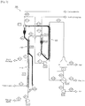
- Fig. 1 illustrates a carbon dioxide capture apparatus according to one embodiment of the present invention in which a heat exchange unit is placed upstream of a sorption column.
- upstream and downstream used herein refer to regions divided based on the circulation pathway of the carbon dioxide absorbent.
- the "upstream of a sorption column” refers to the region through which the carbon dioxide absorbent passes before entering the sorption column
- the "downstream of a sorption column” refers to the region through which the carbon dioxide absorbent passes after escaping from the sorption column.
- the carbon dioxide capture apparatus 100 includes a carbon dioxide adsorption unit 110, a carbon dioxide desorption unit 120, and a heat exchange unit 130.
- the carbon dioxide adsorption unit 110 and the carbon dioxide desorption unit 120 are connected to each other.
- a carbon dioxide absorbent is filled in the carbon dioxide adsorption unit 110 and the carbon dioxide desorption unit 120 to repeatedly adsorb and desorb carbon dioxide while circulating through the carbon dioxide adsorption unit 110 and the carbon dioxide desorption unit 120.
- a flue gas is supplied to the bottom of the carbon dioxide adsorption unit 110. Carbon dioxide is adsorbed to the absorbent in the carbon dioxide adsorption unit 110, which is an inner tube of a sorption column SC1. The flue gas free from carbon dioxide is released to the outside.
- the absorbent after carbon dioxide adsorption passes through an outer tube of the heat exchange unit 130 via a stream number S18 and passes through the carbon dioxide desorption unit 120, an outer tube of a desorption column RC3, via a stream number S15.
- the adsorbed carbon dioxide is desorbed from the carbon dioxide absorbent in the carbon dioxide desorption unit 120.
- the desorbed carbon dioxide is released to the outside.
- the absorbent after carbon dioxide desorption passes through an inner tube of the heat exchange unit 130 via a stream number S17 and again circulates through the carbon dioxide adsorption unit 110. At this time, the absorbent after carbon dioxide desorption and the absorbent after carbon dioxide adsorption are moved in different directions each other through the inner and outer tubes of the heat exchange unit 130, respectively, where heat exchange takes places therebetween.
- the carbon dioxide adsorption unit is cooled by water circulation and the carbon dioxide desorption unit is heated by a heater.
- the heat exchange unit is placed upstream of the sorption column for sensible heat exchange between the absorbent after carbon dioxide adsorption and the absorbent after carbon dioxide desorption.
- the absorbent escaping from the sorption column after carbon dioxide adsorption and the absorbent escaping from the desorption column after carbon dioxide desorption exchange sensible heat while flowing in counter-current directions through a heat exchanger HX1.
- the concentration of the absorbent separated in a cyclone CY1 of the sorption column maintains high bubbling fluidized bed conditions in the range of 15 to 70 vol%.
- the absorbent after carbon dioxide adsorption can exchange heat through the walls of the heat exchanger.
- the concentration of the absorbent separated in a cyclone CY2 of the desorption column maintains dilute fluidized bed conditions in the range of 0.5 to 5 vol%.
- the absorbent after carbon dioxide desorption can exchange heat before entering the sorption column. This construction is advantageous when the absorbent does not rapidly lose its ability to absorb carbon dioxide despite the increasing temperature of the sorption column upon carbon dioxide adsorption and has the advantage of higher sensible heat exchange rate than a construction in which the heat exchange unit is placed downstream of the sorption column.
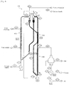
- Fig. 2 illustrates a carbon dioxide capture apparatus according to one embodiment of the present invention in which a heat exchange unit is placed downstream of a sorption column.
- the carbon dioxide capture apparatus 200 includes a carbon dioxide adsorption unit 210, a carbon dioxide desorption unit 220, and a heat exchange unit 230.
- the carbon dioxide adsorption unit 210 and the carbon dioxide desorption unit 220 are connected to each other.
- a carbon dioxide absorbent is filled in the carbon dioxide adsorption unit 210 and the carbon dioxide desorption unit 220 to repeatedly adsorb and desorb carbon dioxide while circulating through the carbon dioxide adsorption unit 210 and the carbon dioxide desorption unit 220.
- a flue gas is supplied to the bottom of the carbon dioxide adsorption unit 210.
- Carbon dioxide is adsorbed to the absorbent in the carbon dioxide adsorption unit 210, which is an inner tube of a sorption column SC1.
- the flue gas free from carbon dioxide passes through the heat exchange unit 230 and is released to the outside.
- the absorbent after carbon dioxide adsorption passes through an inner tube of the heat exchange unit 230 and enters the carbon dioxide desorption unit 220, an outer tube of a desorption column RC3, via stream numbers S22 and S15.
- the adsorbed carbon dioxide is desorbed from the carbon dioxide absorbent in the carbon dioxide desorption unit 220.
- the absorbent after carbon dioxide desorption passes through an outer tube of the heat exchange unit 230 via a stream number S16 and again circulates through the carbon dioxide adsorption unit 210.
- the absorbent after carbon dioxide desorption and the absorbent after carbon dioxide adsorption are moved in different directions each other through the outer and inner tubes of the heat exchange unit 230, respectively, where heat exchange takes places therebetween.
- a heat exchanger is installed downstream of the sorption column for sensible heat exchange between the absorbent after carbon dioxide adsorption and the absorbent after carbon dioxide desorption.
- the absorbent escaping from the sorption column after carbon dioxide adsorption and the absorbent escaping from the desorption column after carbon dioxide desorption exchange sensible heat while flowing in counter-current directions through the heat exchanger HX1.
- the concentration of the absorbent escaping from the sorption column immediately after carbon dioxide adsorption maintains dilute fluidized bed conditions in the range of 0.5 to 5 vol%. Within this range, the absorbent after carbon dioxide adsorption can exchange heat through the walls of the heat exchanger. The concentration of the absorbent separated in a cyclone CY2 of the desorption column maintains high bubbling fluidized bed conditions in the range of 15 to 70 vol%. Within this range, the absorbent after carbon dioxide desorption can exchange heat.
- This construction is advantageous when the absorbent rapidly loses its ability to absorb carbon dioxide with increasing temperature of the sorption column upon carbon dioxide adsorption and has the disadvantage of lower sensible heat exchange rate than a construction in which the heat exchange unit is placed upstream of the sorption column.
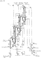
- Fig. 3 illustrates a carbon dioxide capture apparatus according to one embodiment of the present invention in which a heat exchange unit is placed upstream of a desorption column.
- the carbon dioxide capture apparatus 300 includes a carbon dioxide adsorption unit 310, a carbon dioxide desorption unit 320, and a heat exchange unit 330.
- the carbon dioxide adsorption unit 310 and the carbon dioxide desorption unit 320 are connected to each other.
- a carbon dioxide absorbent is filled in the carbon dioxide adsorption unit 310 and the carbon dioxide desorption unit 320 to repeatedly adsorb and desorb carbon dioxide while circulating through the carbon dioxide adsorption unit 310 and the carbon dioxide desorption unit 320.
- a flue gas is supplied to the bottom of the carbon dioxide adsorption unit 310.
- Carbon dioxide is adsorbed to the absorbent in the carbon dioxide adsorption unit 310, which is an inner tube of a sorption column SC1.
- the flue gas free from carbon dioxide is released to the outside.
- the absorbent after carbon dioxide adsorption passes through an inner tube of the heat exchange unit 330 via stream numbers S21 and S15 and passes through the carbon dioxide desorption unit 320, an inner tube of a desorption column RC1, via a stream number S22.
- the adsorbed carbon dioxide is desorbed from the carbon dioxide absorbent in the carbon dioxide desorption unit 320.
- the absorbent after carbon dioxide desorption passes through an outer tube of the heat exchange unit 330 via a stream number S17 and again circulates through the carbon dioxide adsorption unit 310. At this time, the absorbent after carbon dioxide desorption and the absorbent after carbon dioxide adsorption are moved in different directions each other through the outer and inner tubes of the heat exchange unit 330, respectively, where heat exchange takes places therebetween.
- a heat exchanger is installed upstream of the desorption column for sensible heat exchange between the absorbent after carbon dioxide adsorption and the absorbent after carbon dioxide desorption.
- the concentration of the absorbent separated in a cyclone CY1 of the sorption column maintains dilute fluidized bed conditions in the range of 0.5 to 5 vol%. Within this range, the absorbent after carbon dioxide adsorption can exchange heat through the walls of the heat exchanger before entering the desorption column.
- the concentration of the absorbent separated in a cyclone CY2 of the desorption column maintains high bubbling fluidized bed conditions in the range of 15 to 70 vol%. Within this range, the absorbent after carbon dioxide desorption can exchange heat.
- This construction is advantageous when the absorbent after carbon dioxide adsorption rapidly desorbs the adsorbed carbon dioxide with increasing temperature and has the advantage of higher sensible heat exchange rate than a construction in which the heat exchange unit is placed downstream of the desorption column.
- Fig. 4 illustrates a carbon dioxide capture apparatus according to one embodiment of the present invention in which a heat exchange unit is placed downstream of a desorption column.
- the carbon dioxide capture apparatus 400 includes a carbon dioxide adsorption unit 410, a carbon dioxide desorption unit 420, and a heat exchange unit 430.
- the carbon dioxide adsorption unit 410 and the carbon dioxide desorption unit 420 are connected to each other.
- a carbon dioxide absorbent is filled in the carbon dioxide adsorption unit 410 and the carbon dioxide desorption unit 420 to repeatedly adsorb and desorb carbon dioxide while circulating through the carbon dioxide adsorption unit 410 and the carbon dioxide desorption unit 420.
- a flue gas is supplied to the bottom of the carbon dioxide adsorption unit 410, which is an inner tube of a sorption column SC1. Carbon dioxide is adsorbed to the absorbent in the carbon dioxide adsorption unit 410 and the flue gas free from carbon dioxide is released to the outside.
- the absorbent after carbon dioxide adsorption passes through an outer tube of the heat exchange unit 430 via stream numbers S21 and S15 and passes through the carbon dioxide desorption unit 420, an inner tube of a desorption column RC3, via a stream number S22.
- the adsorbed carbon dioxide is desorbed from the carbon dioxide absorbent in the carbon dioxide desorption unit 420.
- the absorbent after carbon dioxide desorption passes through an inner tube of the heat exchange unit 430 via a stream number S16 and again circulates through the carbon dioxide adsorption unit 410. At this time, the absorbent after carbon dioxide desorption and the absorbent after carbon dioxide adsorption are moved in different directions each other through the inner and outer tubes of the heat exchange unit 430, respectively, where heat exchange takes places therebetween.
- a heat exchanger is installed downstream of the desorption column for sensible heat exchange between the absorbent after carbon dioxide adsorption and the absorbent after carbon dioxide desorption.
- the concentration of the absorbent separated in a cyclone CY1 of the sorption column maintains high bubbling fluidized bed conditions in the range of 15 to 70 vol%. Within this range, the absorbent after carbon dioxide adsorption can exchange heat through the walls of the heat exchanger before entering the desorption column.
- the concentration of the absorbent escaping from the desorption column immediately after carbon dioxide desorption maintains dilute fluidized bed conditions in the range of 0.5 to 5 vol%. Within this range, the absorbent after carbon dioxide desorption can exchange heat.
- This construction is advantageous when the absorbent after carbon dioxide adsorption does not rapidly readsorb carbon dioxide despite drop in temperature and has the disadvantage of lower sensible heat exchange rate than a construction in which the heat exchange unit is placed upstream of the desorption column.
- the sorption column and the regeneration column of each carbon dioxide capture apparatus consist of a combination of bubbling fluidized bed-dilute fluidized bed or dilute fluidized bed-bubbling fluidized bed. This combination has the problem of low heat exchange efficiency.
- the heat exchanger of each carbon dioxide capture apparatus is structurally designed to have a large heat exchange area, which facilitates direct heat exchange.
- Figs. 5 and 6 illustrate the constructions of a multi-tube heat exchanger and a multi-plate type heat exchanger applicable to the carbon dioxide capture apparatus of the present invention, respectively.
- the absorbent after carbon dioxide desorption in the desorption column is moved upward along an outer tube whose diameter is larger and the absorbent after carbon dioxide adsorption in the sorption column is moved downward through a plurality of inner tubes.
- This structure increases the surface area of the inner tubes, leading to an increase in the efficiency of heat exchange between the absorbent after carbon dioxide desorption and the absorbent after carbon dioxide adsorption.
- the absorbent passing through the inner tubes is interchangeable with the absorbent passing through the outer tube.
- the heat exchanger consists of plates, each having an internal space and a small thickness.
- the absorbent after carbon dioxide desorption passes through the internal spaces of the plates and the absorbent after carbon dioxide adsorption passes through spaces defined by the plates.
- the internal passages of the plates are disposed alternately and in face-to-face contact with the passages defined by the plates. This structure increases the area where the absorbent after carbon dioxide adsorption exchanges heat with the absorbent after carbon dioxide desorption, leading to an increase in heat exchange efficiency.
- sensible heat is effectively exchanged between the absorbent after carbon dioxide adsorption and the absorbent after carbon dioxide desorption in the single-stage circulating fluidized bed reactors.
- Such sensible heat exchange occurs more effectively in multi-stage circulating fluidized bed processes for carbon dioxide capture in which adsorption heat and desorption heat of absorbents operating at different temperatures are exchanged, as illustrated in Figs. 9 and 10 .
- heat exchangers capable of directly exchanging sensible heat between the absorbents can be installed to minimize the cost of energy consumed to capture carbon dioxide.
- Figs. 7 and 8 are diagrams for explaining the concept of using heat of carbon dioxide adsorption as heat necessary for the desorption of carbon dioxide in a carbon dioxide adsorption-desorption cycle consisting of a low temperature stage, an intermediate temperature stage, and a high temperature stage in accordance with a multi-stage carbon dioxide capture method according to the disclosure.
- carbon dioxide adsorption/desorption units in which carbon dioxide is adsorbed and desorbed at different temperatures are multi-stage connected in series. This connection enables the transfer of energy between the carbon dioxide adsorption/desorption units in which carbon dioxide adsorption and desorption occurs.
- absorbents having different adsorption and desorption temperatures are filled in the high temperature, intermediate temperature, and low temperature carbon dioxide adsorption/desorption units, adsorption heat is generated in the course of adsorbing carbon dioxide and is transferred to the adjacent stage to induce the desorption of carbon dioxide or reduce the amount of heat necessary for desorption.
- adsorption heat is emitted when the absorbent adsorbs carbon dioxide in the high temperature stage and is used as energy necessary for the absorbent in the intermediate temperature stage to desorb the carbon dioxide
- adsorption heat is emitted when the absorbent adsorbs carbon dioxide in the intermediate temperature stage and is used as energy necessary for the absorbent in the low temperature stage to desorb the carbon dioxide.
- the use of energy generated during adsorption of carbon dioxide as energy necessary for the desorption of carbon dioxide can reduce the cost of energy consumed to desorb the carbon dioxide.
- the absorbent escaping from the sorption column after carbon dioxide adsorption enters the desorption column to desorb the absorbed carbon dioxide.
- heating of the absorbent after carbon dioxide adsorption to the desorption temperature is required for carbon dioxide desorption.
- the hot absorbent escaping from the desorption column after carbon dioxide desorption should be cooled to the adsorption temperature in order for the absorbent to reabsorb carbon dioxide in the sorption column.
- heat exchange between the lower temperature absorbent escaping from the sorption column and the higher temperature absorbent escaping from the desorption column can save energy cost for heating the absorbent escaping from the sorption column and cooling the absorbent escaping from the desorption column.
- the energy efficiency of the entire process is determined depending on how efficient the heat exchange is.
- Figs. 9 and 10 illustrate carbon dioxide capture processes consisting of multi-stage carbon dioxide adsorption-desorption cycles. As illustrated in Figs. 9 and 10 , heat exchangers are installed downstream of the sorption columns and upstream of the desorption columns for direct sensible heat exchange between absorbents after carbon dioxide adsorption and absorbents after carbon dioxide desorption, respectively.
- Fig. 9 illustrates a multi-stage carbon dioxide capture apparatus according to one embodiment of the present invention in which heat exchange units are disposed downstream of sorption columns.
- the three-stage carbon dioxide capture apparatus illustrated in Fig. 9 is operated in direct adsorption heat exchange and sensible heat exchange modes and includes three carbon dioxide adsorption/desorption units in which carbon dioxide adsorption and desorption occurs.
- Each of the carbon dioxide adsorption/desorption units uses a carbon dioxide absorbent operating at a high, intermediate or low temperature (the concept of temperature is relative). Heat exchange occurs between the adjacent carbon dioxide adsorption/desorption units.
- the carbon dioxide capture apparatus uses an absorption-desorption process in a direct heat exchange mode and consists of low, intermediate, and high temperature stages in which sorption columns and desorption columns are dilute fluidized bed reactors.
- Sensible heat exchangers 530a, 530b, and 530c for direct heat exchange between the absorbents are arranged downstream of the respective sorption columns so that the cost of energy consumed to capture carbon dioxide can be minimized. This construction is very advantageous when the absorbents do not readily desorb the adsorbed carbon dioxide even at the increased temperature after carbon dioxide adsorption.
- Fig. 10 illustrates a multi-stage carbon dioxide capture apparatus according to one embodiment of the present invention in which heat exchange units are disposed upstream of desorption columns.
- the three-stage carbon dioxide capture apparatus illustrated in Fig. 10 is operated in direct adsorption heat exchange and sensible heat exchange modes and includes three carbon dioxide adsorption/desorption units in which carbon dioxide adsorption and desorption occurs.
- Each of the carbon dioxide adsorption/desorption units uses a carbon dioxide absorbent operating at a high, intermediate or low temperature (the concept of temperature is relative). Heat exchange occurs between the adjacent carbon dioxide adsorption/desorption units.
- the carbon dioxide capture apparatus uses an absorption-desorption process in a direct heat exchange mode and consists of low, intermediate, and high temperature stages in which sorption columns and desorption columns are dilute fluidized bed reactors.
- Sensible heat exchangers 630a, 630b, and 630c for direct heat exchange between the absorbents are arranged upstream of the respective desorption columns, so that the cost of energy consumed to capture carbon dioxide can be minimized. This construction is very advantageous when the absorbents readily desorb the adsorbed carbon dioxide at the increased temperature after carbon dioxide adsorption.
Landscapes
- Chemical & Material Sciences (AREA)
- Engineering & Computer Science (AREA)
- Chemical Kinetics & Catalysis (AREA)
- Analytical Chemistry (AREA)
- General Chemical & Material Sciences (AREA)
- Oil, Petroleum & Natural Gas (AREA)
- Dispersion Chemistry (AREA)
- Health & Medical Sciences (AREA)
- Biomedical Technology (AREA)
- Environmental & Geological Engineering (AREA)
- Organic Chemistry (AREA)
- Carbon And Carbon Compounds (AREA)
- Treating Waste Gases (AREA)
- Solid-Sorbent Or Filter-Aiding Compositions (AREA)
Claims (4)
- Appareil de captage de dioxyde de carbone (100) présentant un mode d'adsorption à température alternée pour une séparation sélective de dioxyde de carbone de gaz de combustion contenant des dioxydes de carbone, comprenant :une colonne d'adsorption de dioxyde de carbone (SC1) incluant une unité d'adsorption de dioxyde de carbone (110) dans laquelle une adsorption de dioxyde de carbone de gaz de combustion se déroule ;une colonne de désorption de dioxyde de carbone (RC3) raccordée à la colonne d'adsorption de dioxyde de carbone (SC1) et incluant une unité de désorption de dioxyde de carbone (120) dans laquelle une désorption du dioxyde de carbone adsorbé se déroule ;un adsorbant de dioxyde de carbone adsorbant et désorbant à répétition du dioxyde de carbone en circulant à travers la colonne d'adsorption de dioxyde de carbone (SC1) et la colonne de désorption de dioxyde de carbone (RC3) ; etune unité d'échange de chaleur (130), dans laquelle un échange de chaleur se déroule entre l'adsorbant après l'adsorption de dioxyde de carbone et l'adsorbant après la désorption de dioxyde de carbone,caractérisé en ce que la colonne d'adsorption de dioxyde de carbone (SC1) et l'unité d'échange de chaleur (130) comprennent un tube intérieur, dans lequel le tube intérieur de la colonne d'adsorption de dioxyde de carbone (SC1) est une prolongation verticalement vers le haut du tube intérieur de l'unité d'échange de chaleur (130), etl'adsorbant après la sortie de la colonne de désorption de dioxyde de carbone (RC3) passe le tube intérieur de l'unité d'échange de chaleur (130) avant de se déplacer vers le haut à travers le tube intérieur de la colonne d'adsorption de dioxyde de carbone (SC1), etl'adsorbant après la sortie de la colonne d'adsorption de dioxyde de carbone (SC1) passe à travers un tube extérieur de l'unité d'échange de chaleur (130),dans lequel l'adsorbant après l'adsorption de dioxyde de carbone et l'adsorbant après la désorption de dioxyde de carbone sont déplacés respectivement dans des conditions de lit fluidisé bouillonnant et dans des conditions de lit fluidisé dilué dans l'unité d'échange de chaleur (130), dans lequel l'adsorbant s'échappant de la colonne d'adsorption de dioxyde de carbone (SC1) après l'adsorption de dioxyde de carbone et l'adsorbant s'échappant de la colonne de désorption de dioxyde de carbone (RC3) après la désorption de dioxyde de carbone échangent une chaleur sensible en s'écoulant dans des sens à contre-courant à travers l'unité d'échange de chaleur (130).
- Appareil de captage de dioxyde de carbone (200) présentant un mode d'adsorption à température alternée pour une séparation sélective de dioxyde de carbone de gaz de combustion contenant des dioxydes de carbone, comprenant :une colonne d'adsorption de dioxyde de carbone (SC1) incluant une unité d'adsorption de dioxyde de carbone (210) dans laquelle une adsorption de dioxyde de carbone de gaz de combustion se déroule ;une colonne de désorption de dioxyde de carbone (RC3) raccordée à la colonne d'adsorption de dioxyde de carbone (SC1) et incluant une unité de désorption de dioxyde de carbone (220) dans laquelle une désorption du dioxyde de carbone adsorbé se déroule ;un adsorbant de dioxyde de carbone adsorbant et désorbant à répétition du dioxyde de carbone en circulant à travers la colonne d'adsorption de dioxyde de carbone (SC1) et la colonne de désorption de dioxyde de carbone (RC3) ; etune unité d'échange de chaleur (230), dans laquelle un échange de chaleur se déroule entre l'adsorbant après l'adsorption de dioxyde de carbone et l'adsorbant après la désorption de dioxyde de carbone,caractérisé en ce que la colonne d'adsorption de dioxyde de carbone (SC1) et l'unité d'échange de chaleur (230) comprennent un tube intérieur, dans lequel le tube intérieur de l'unité d'échange de chaleur (230) est une prolongation verticalement vers le haut du tube intérieur de la colonne d'adsorption de dioxyde de carbone (SC1), etdans lequel l'adsorbant après la sortie du tube intérieur de la colonne d'adsorption de dioxyde de carbone (SC1) se déplace vers le haut à travers le tube intérieur de l'unité d'échange de chaleur (230), etdans lequel l'adsorbant après la sortie de la colonne de désorption de dioxyde de carbone (RC3) passe à travers un tube extérieur de l'unité d'échange de chaleur (230), etdans lequel l'adsorbant après l'adsorption de dioxyde de carbone et l'adsorbant après la désorption de dioxyde de carbone sont déplacés respectivement dans des conditions de lit fluidisé dilué et dans des conditions de lit fluidisé bouillonnant dans l'unité d'échange de chaleur (230),dans lequel l'adsorbant s'échappant de la colonne d'adsorption après l'adsorption de dioxyde de carbone et l'adsorbant s'échappant de la colonne de désorption après la désorption de dioxyde de carbone échangent une chaleur sensible en s'écoulant dans des sens à contre-courant à travers l'unité d'échange de chaleur (230).
- Appareil de captage de dioxyde de carbone (300) présentant un mode d'adsorption à température alternée pour une séparation sélective de dioxyde de carbone de gaz de combustion contenant des dioxydes de carbone, comprenant :une colonne d'adsorption de dioxyde de carbone (SC1) incluant une unité d'adsorption de dioxyde de carbone (310) dans laquelle une adsorption de dioxyde de carbone de gaz de combustion se déroule ;une colonne de désorption de dioxyde de carbone (RC1) raccordée à la colonne d'adsorption de dioxyde de carbone (SC1) et incluant une unité de désorption de dioxyde de carbone (320) dans laquelle une désorption du dioxyde de carbone adsorbé se déroule ;un adsorbant de dioxyde de carbone adsorbant et désorbant à répétition du dioxyde de carbone en circulant à travers la colonne d'adsorption de dioxyde de carbone (SC1) et la colonne de désorption de dioxyde de carbone (RC1) ; etune unité d'échange de chaleur (330), dans laquelle un échange de chaleur se déroule entre l'adsorbant après l'adsorption de dioxyde de carbone et l'adsorbant après la désorption de dioxyde de carbone,caractérisé en ce que la colonne de désorption de dioxyde de carbone (RC1) et l'unité d'échange de chaleur (330) comprennent un tube intérieur, dans lequel le tube intérieur de la colonne de désorption de dioxyde de carbone (RC1) est une prolongation verticalement vers le haut du tube intérieur de l'unité d'échange de chaleur (330), etl'adsorbant après la sortie de la colonne d'adsorption de dioxyde de carbone (SC1) passe le tube intérieur de l'unité d'échange de chaleur (330) avant de se déplacer vers le haut à travers le tube intérieur de la colonne de désorption de dioxyde de carbone (RC1), etl'adsorbant après la sortie de la colonne de désorption de dioxyde de carbone (RC1) passe à travers un tube extérieur de l'unité d'échange de chaleur (330),dans lequel l'adsorbant après l'adsorption de dioxyde de carbone et l'adsorbant après la désorption de dioxyde de carbone sont déplacés respectivement dans des conditions de lit fluidisé dilué et dans des conditions de lit fluidisé bouillonnant dans l'unité d'échange de chaleur (330),dans lequel l'adsorbant s'échappant de la colonne d'adsorption après l'adsorption de dioxyde de carbone et l'adsorbant s'échappant de la colonne de désorption après la désorption de dioxyde de carbone échangent une chaleur sensible en s'écoulant dans des sens à contre-courant à travers l'unité d'échange de chaleur (330).
- Appareil de captage de dioxyde de carbone (400) présentant un mode d'adsorption à température alternée pour une séparation sélective de dioxyde de carbone de gaz de combustion contenant des dioxydes de carbone, comprenant :une colonne d'adsorption de dioxyde de carbone (SC1) incluant une unité d'adsorption de dioxyde de carbone (410) dans laquelle une adsorption de dioxyde de carbone de gaz de combustion se déroule ;une colonne de désorption de dioxyde de carbone (RC3) raccordée à la colonne d'adsorption de dioxyde de carbone (SC1) et incluant une unité de désorption de dioxyde de carbone (420) dans laquelle une désorption du dioxyde de carbone adsorbé se déroule ;un adsorbant de dioxyde de carbone adsorbant et désorbant à répétition du dioxyde de carbone en circulant à travers la colonne d'adsorption de dioxyde de carbone (SC1) et la colonne de désorption de dioxyde de carbone (RC3) ; etune unité d'échange de chaleur (430), dans laquelle un échange de chaleur se déroule entre l'adsorbant après l'adsorption de dioxyde de carbone et l'adsorbant après la désorption de dioxyde de carbone,caractérisé en ce que la colonne de désorption de dioxyde de carbone (RC3) et l'unité d'échange de chaleur (430) comprennent un tube intérieur, dans lequel le tube intérieur de l'unité d'échange de chaleur (430) est une prolongation verticalement vers le haut du tube intérieur de la colonne de désorption de dioxyde de carbone (RC3), etl'adsorbant après la sortie de la colonne de désorption de dioxyde de carbone (RC3) se déplace vers le haut à travers le tube intérieur de l'unité d'échange de chaleur (430), etl'adsorbant après la sortie de la colonne d'adsorption de dioxyde de carbone (SC1) passe à travers un tube extérieur de l'unité d'échange de chaleur (430),dans lequel l'adsorbant après l'adsorption de dioxyde de carbone et l'adsorbant après la désorption de dioxyde de carbone sont déplacés respectivement dans des conditions de lit fluidisé bouillonnant et dans des conditions de lit fluidisé dilué dans l'unité d'échange de chaleur (430),dans lequel l'adsorbant s'échappant de la colonne d'adsorption après l'adsorption de dioxyde de carbone et l'adsorbant s'échappant de la colonne de désorption après la désorption de dioxyde de carbone échangent une chaleur sensible en s'écoulant dans des sens à contre-courant à travers l'unité d'échange de chaleur (430).
Applications Claiming Priority (2)
| Application Number | Priority Date | Filing Date | Title |
|---|---|---|---|
| KR20130026593 | 2013-03-13 | ||
| PCT/KR2014/002078 WO2014142556A1 (fr) | 2013-03-13 | 2014-03-12 | Dispositif de collecte de dioxyde de carbone |
Publications (3)
| Publication Number | Publication Date |
|---|---|
| EP2954942A1 EP2954942A1 (fr) | 2015-12-16 |
| EP2954942A4 EP2954942A4 (fr) | 2017-04-26 |
| EP2954942B1 true EP2954942B1 (fr) | 2020-01-01 |
Family
ID=51537103
Family Applications (1)
| Application Number | Title | Priority Date | Filing Date |
|---|---|---|---|
| EP14762615.4A Active EP2954942B1 (fr) | 2013-03-13 | 2014-03-12 | Dispositif de collecte de dioxyde de carbone |
Country Status (5)
| Country | Link |
|---|---|
| US (1) | US9694312B2 (fr) |
| EP (1) | EP2954942B1 (fr) |
| KR (1) | KR101571966B1 (fr) |
| ES (1) | ES2768619T3 (fr) |
| WO (1) | WO2014142556A1 (fr) |
Families Citing this family (6)
| Publication number | Priority date | Publication date | Assignee | Title |
|---|---|---|---|---|
| JP2019512662A (ja) * | 2016-03-31 | 2019-05-16 | インベンティーズ サーマル テクノロジーズ インコーポレイテッド | 温度変動吸着式ガス分離 |
| WO2018057780A1 (fr) | 2016-09-21 | 2018-03-29 | Donald Williams | Système, appareil et procédé de capture de carbone |
| US10150096B2 (en) * | 2017-03-20 | 2018-12-11 | Wisys Technology Foundation, Inc. | Heteroatom rich organic polymers with ultra-small pore apertures for carbon dioxide separation and/or conversion |
| EP3646935A1 (fr) * | 2018-10-30 | 2020-05-06 | Ecole Polytechnique Federale de Lausanne (EPFL) | Système de capture de co2 issu d'un moteur à combustion interne |
| KR102165888B1 (ko) * | 2019-01-25 | 2020-10-15 | 한국에너지기술연구원 | 고체고체 열교환기 및 그 열교환기를 이용한 건식 이산화탄소 포집장치 |
| KR102033745B1 (ko) * | 2019-06-28 | 2019-10-17 | 한국화학연구원 | 이산화탄소 포집장치 및 포집공정 |
Family Cites Families (13)
| Publication number | Priority date | Publication date | Assignee | Title |
|---|---|---|---|---|
| US2904507A (en) * | 1957-07-11 | 1959-09-15 | Exxon Research Engineering Co | Fluidized molecular sieve process |
| JP2001137646A (ja) | 1999-11-15 | 2001-05-22 | Kureha Techno Enji Kk | 排ガスの吸着処理装置及び方法 |
| KR100527420B1 (ko) | 2003-07-04 | 2005-11-09 | 한국에너지기술연구원 | Co2 분리회수장치 |
| JP5470671B2 (ja) * | 2005-10-18 | 2014-04-16 | 独立行政法人産業技術総合研究所 | デシカント空調装置 |
| JP2008307520A (ja) * | 2007-06-18 | 2008-12-25 | Mitsubishi Heavy Ind Ltd | Co2又はh2s除去システム、co2又はh2s除去方法 |
| US8133305B2 (en) * | 2007-11-05 | 2012-03-13 | Kilimanjaro Energy, Inc. | Removal of carbon dioxide from air |
| CN101592449B (zh) * | 2008-05-29 | 2012-01-25 | 中国石油化工股份有限公司 | 一种烟气脱硫脱氮吸附剂再生过程中的换热方法 |
| KR101069191B1 (ko) | 2009-03-04 | 2011-09-30 | 한국에너지기술연구원 | 수송 재생반응기를 갖는 co₂회수장치 |
| US8303696B2 (en) * | 2009-07-10 | 2012-11-06 | Southern Company | Carbon dioxide absorber and regeneration assemblies useful for power plant flue gas |
| AU2010226936B2 (en) * | 2009-10-07 | 2012-03-15 | Kabushiki Kaisha Toshiba | CO2 recovery system and CO2 absorption liquid |
| KR101045061B1 (ko) | 2009-11-19 | 2011-06-29 | 한국에너지기술연구원 | 다단유동층 열교환기 형태의 재생반응기를 갖는 co₂회수장치 |
| KR101233297B1 (ko) * | 2010-11-30 | 2013-02-14 | 한국에너지기술연구원 | 건식 이산화탄소 포집장치 |
| KR101381443B1 (ko) * | 2012-06-27 | 2014-04-04 | 한국화학연구원 | 이산화탄소 포집장치 |
-
2014
- 2014-03-12 US US14/773,968 patent/US9694312B2/en active Active
- 2014-03-12 EP EP14762615.4A patent/EP2954942B1/fr active Active
- 2014-03-12 ES ES14762615T patent/ES2768619T3/es active Active
- 2014-03-12 KR KR1020140029238A patent/KR101571966B1/ko active IP Right Grant
- 2014-03-12 WO PCT/KR2014/002078 patent/WO2014142556A1/fr active Application Filing
Non-Patent Citations (1)
| Title |
|---|
| None * |
Also Published As
| Publication number | Publication date |
|---|---|
| US9694312B2 (en) | 2017-07-04 |
| KR101571966B1 (ko) | 2015-11-26 |
| EP2954942A1 (fr) | 2015-12-16 |
| EP2954942A4 (fr) | 2017-04-26 |
| WO2014142556A1 (fr) | 2014-09-18 |
| ES2768619T3 (es) | 2020-06-23 |
| KR20140112443A (ko) | 2014-09-23 |
| US20160016108A1 (en) | 2016-01-21 |
Similar Documents
| Publication | Publication Date | Title |
|---|---|---|
| EP2954942B1 (fr) | Dispositif de collecte de dioxyde de carbone | |
| JP6498483B2 (ja) | ガス回収濃縮装置 | |
| US8894753B2 (en) | Carbon dioxide capture systems | |
| KR102033745B1 (ko) | 이산화탄소 포집장치 및 포집공정 | |
| CN104168978A (zh) | 用于从气流中去除二氧化碳的工艺 | |
| KR101146710B1 (ko) | 연소배가스에서 온도변동 흡착공정을 이용한 이산화탄소를 회수 장치 및 그 운전방법 | |
| CN113975938B (zh) | 一种旋转式低温吸附捕集烟气中二氧化碳的装置及方法 | |
| CN104162341A (zh) | 一种固态胺吸附剂脱除烟气中co2的装置及方法 | |
| CN110772927B (zh) | 并列管式气体吸附浓集装置 | |
| CN102266702A (zh) | 一种捕集工业废气中氨气的方法和设备及其应用 | |
| CN109794137B (zh) | 一种吸附净化并富集回收烟气氮氧化物的方法及系统 | |
| CN111841066A (zh) | 一种烟气中酸性气体脱除系统及方法 | |
| CN112263890A (zh) | 一种烟气余热利用型碳捕集方法和系统 | |
| CN116059784A (zh) | 一种变压吸附捕集烟气二氧化碳的方法及系统 | |
| CN202942787U (zh) | 一种污染物脱除工艺/吸附剂再生工艺可切换的烟气净化系统 | |
| JP2009090979A (ja) | 小型デシカント空調装置 | |
| CN113813744A (zh) | 一种提升燃煤锅炉烟气中co2捕集经济性的系统和方法 | |
| JP3240788U (ja) | 連続空気中の二酸化炭素の直接捕集システム | |
| JP2009083851A (ja) | 小型デシカント空調装置 | |
| CN109173568B (zh) | 一种活性炭级差吸附安全浓缩方法 | |
| CN212236611U (zh) | 一种切换式固定床烟气处理系统 | |
| WO2019073866A1 (fr) | Procédé de séparation/récupération de co2 et équipement de séparation/récupération de co2 | |
| KR102608674B1 (ko) | 선박의 배가스 폐열을 이용한 이산화탄소 흡착제 재생을 포함하는 선박의 배가스내 이산화탄소 포집 시스템 및 이의 포집방법 | |
| CN212269983U (zh) | 焦炉装煤烟气净化系统 | |
| WO2023145721A1 (fr) | Procédé et dispositif de récupération de co2 |
Legal Events
| Date | Code | Title | Description |
|---|---|---|---|
| PUAI | Public reference made under article 153(3) epc to a published international application that has entered the european phase |
Free format text: ORIGINAL CODE: 0009012 |
|
| 17P | Request for examination filed |
Effective date: 20150907 |
|
| AK | Designated contracting states |
Kind code of ref document: A1 Designated state(s): AL AT BE BG CH CY CZ DE DK EE ES FI FR GB GR HR HU IE IS IT LI LT LU LV MC MK MT NL NO PL PT RO RS SE SI SK SM TR |
|
| AX | Request for extension of the european patent |
Extension state: BA ME |
|
| RIN1 | Information on inventor provided before grant (corrected) |
Inventor name: KANG, NA YOUNG Inventor name: CHOI, WON CHOON Inventor name: SEO, HWI MIN Inventor name: PARK, YONG KI |
|
| DAX | Request for extension of the european patent (deleted) | ||
| RIC1 | Information provided on ipc code assigned before grant |
Ipc: B01D 53/04 20060101ALI20161024BHEP Ipc: B01D 53/62 20060101ALI20161024BHEP Ipc: B01D 53/12 20060101ALI20161024BHEP Ipc: B01D 53/14 20060101AFI20161024BHEP Ipc: B01D 53/08 20060101ALI20161024BHEP Ipc: B01D 53/96 20060101ALI20161024BHEP |
|
| A4 | Supplementary search report drawn up and despatched |
Effective date: 20170327 |
|
| RIC1 | Information provided on ipc code assigned before grant |
Ipc: B01D 53/12 20060101ALI20170321BHEP Ipc: B01D 53/62 20060101ALI20170321BHEP Ipc: F28D 7/10 20060101ALI20170321BHEP Ipc: B01D 53/96 20060101ALI20170321BHEP Ipc: B01D 53/08 20060101ALI20170321BHEP Ipc: F28D 9/00 20060101ALI20170321BHEP Ipc: B01D 53/14 20060101AFI20170321BHEP Ipc: B01D 53/04 20060101ALI20170321BHEP |
|
| STAA | Information on the status of an ep patent application or granted ep patent |
Free format text: STATUS: EXAMINATION IS IN PROGRESS |
|
| 17Q | First examination report despatched |
Effective date: 20180125 |
|
| GRAP | Despatch of communication of intention to grant a patent |
Free format text: ORIGINAL CODE: EPIDOSNIGR1 |
|
| STAA | Information on the status of an ep patent application or granted ep patent |
Free format text: STATUS: GRANT OF PATENT IS INTENDED |
|
| INTG | Intention to grant announced |
Effective date: 20190724 |
|
| GRAS | Grant fee paid |
Free format text: ORIGINAL CODE: EPIDOSNIGR3 |
|
| GRAA | (expected) grant |
Free format text: ORIGINAL CODE: 0009210 |
|
| STAA | Information on the status of an ep patent application or granted ep patent |
Free format text: STATUS: THE PATENT HAS BEEN GRANTED |
|
| AK | Designated contracting states |
Kind code of ref document: B1 Designated state(s): AL AT BE BG CH CY CZ DE DK EE ES FI FR GB GR HR HU IE IS IT LI LT LU LV MC MK MT NL NO PL PT RO RS SE SI SK SM TR |
|
| REG | Reference to a national code |
Ref country code: GB Ref legal event code: FG4D |
|
| REG | Reference to a national code |
Ref country code: CH Ref legal event code: EP Ref country code: AT Ref legal event code: REF Ref document number: 1219064 Country of ref document: AT Kind code of ref document: T Effective date: 20200115 |
|
| REG | Reference to a national code |
Ref country code: IE Ref legal event code: FG4D |
|
| REG | Reference to a national code |
Ref country code: DE Ref legal event code: R096 Ref document number: 602014059331 Country of ref document: DE |
|
| REG | Reference to a national code |
Ref country code: NO Ref legal event code: T2 Effective date: 20200101 |
|
| REG | Reference to a national code |
Ref country code: NL Ref legal event code: MP Effective date: 20200101 |
|
| REG | Reference to a national code |
Ref country code: ES Ref legal event code: FG2A Ref document number: 2768619 Country of ref document: ES Kind code of ref document: T3 Effective date: 20200623 |
|
| REG | Reference to a national code |
Ref country code: LT Ref legal event code: MG4D |
|
| PG25 | Lapsed in a contracting state [announced via postgrant information from national office to epo] |
Ref country code: CZ Free format text: LAPSE BECAUSE OF FAILURE TO SUBMIT A TRANSLATION OF THE DESCRIPTION OR TO PAY THE FEE WITHIN THE PRESCRIBED TIME-LIMIT Effective date: 20200101 Ref country code: FI Free format text: LAPSE BECAUSE OF FAILURE TO SUBMIT A TRANSLATION OF THE DESCRIPTION OR TO PAY THE FEE WITHIN THE PRESCRIBED TIME-LIMIT Effective date: 20200101 Ref country code: RS Free format text: LAPSE BECAUSE OF FAILURE TO SUBMIT A TRANSLATION OF THE DESCRIPTION OR TO PAY THE FEE WITHIN THE PRESCRIBED TIME-LIMIT Effective date: 20200101 Ref country code: NL Free format text: LAPSE BECAUSE OF FAILURE TO SUBMIT A TRANSLATION OF THE DESCRIPTION OR TO PAY THE FEE WITHIN THE PRESCRIBED TIME-LIMIT Effective date: 20200101 Ref country code: PT Free format text: LAPSE BECAUSE OF FAILURE TO SUBMIT A TRANSLATION OF THE DESCRIPTION OR TO PAY THE FEE WITHIN THE PRESCRIBED TIME-LIMIT Effective date: 20200527 Ref country code: LT Free format text: LAPSE BECAUSE OF FAILURE TO SUBMIT A TRANSLATION OF THE DESCRIPTION OR TO PAY THE FEE WITHIN THE PRESCRIBED TIME-LIMIT Effective date: 20200101 |
|
| PG25 | Lapsed in a contracting state [announced via postgrant information from national office to epo] |
Ref country code: IS Free format text: LAPSE BECAUSE OF FAILURE TO SUBMIT A TRANSLATION OF THE DESCRIPTION OR TO PAY THE FEE WITHIN THE PRESCRIBED TIME-LIMIT Effective date: 20200501 Ref country code: GR Free format text: LAPSE BECAUSE OF FAILURE TO SUBMIT A TRANSLATION OF THE DESCRIPTION OR TO PAY THE FEE WITHIN THE PRESCRIBED TIME-LIMIT Effective date: 20200402 Ref country code: BG Free format text: LAPSE BECAUSE OF FAILURE TO SUBMIT A TRANSLATION OF THE DESCRIPTION OR TO PAY THE FEE WITHIN THE PRESCRIBED TIME-LIMIT Effective date: 20200401 Ref country code: LV Free format text: LAPSE BECAUSE OF FAILURE TO SUBMIT A TRANSLATION OF THE DESCRIPTION OR TO PAY THE FEE WITHIN THE PRESCRIBED TIME-LIMIT Effective date: 20200101 Ref country code: SE Free format text: LAPSE BECAUSE OF FAILURE TO SUBMIT A TRANSLATION OF THE DESCRIPTION OR TO PAY THE FEE WITHIN THE PRESCRIBED TIME-LIMIT Effective date: 20200101 Ref country code: HR Free format text: LAPSE BECAUSE OF FAILURE TO SUBMIT A TRANSLATION OF THE DESCRIPTION OR TO PAY THE FEE WITHIN THE PRESCRIBED TIME-LIMIT Effective date: 20200101 |
|
| REG | Reference to a national code |
Ref country code: DE Ref legal event code: R097 Ref document number: 602014059331 Country of ref document: DE |
|
| PG25 | Lapsed in a contracting state [announced via postgrant information from national office to epo] |
Ref country code: DK Free format text: LAPSE BECAUSE OF FAILURE TO SUBMIT A TRANSLATION OF THE DESCRIPTION OR TO PAY THE FEE WITHIN THE PRESCRIBED TIME-LIMIT Effective date: 20200101 Ref country code: MC Free format text: LAPSE BECAUSE OF FAILURE TO SUBMIT A TRANSLATION OF THE DESCRIPTION OR TO PAY THE FEE WITHIN THE PRESCRIBED TIME-LIMIT Effective date: 20200101 Ref country code: SK Free format text: LAPSE BECAUSE OF FAILURE TO SUBMIT A TRANSLATION OF THE DESCRIPTION OR TO PAY THE FEE WITHIN THE PRESCRIBED TIME-LIMIT Effective date: 20200101 Ref country code: RO Free format text: LAPSE BECAUSE OF FAILURE TO SUBMIT A TRANSLATION OF THE DESCRIPTION OR TO PAY THE FEE WITHIN THE PRESCRIBED TIME-LIMIT Effective date: 20200101 Ref country code: EE Free format text: LAPSE BECAUSE OF FAILURE TO SUBMIT A TRANSLATION OF THE DESCRIPTION OR TO PAY THE FEE WITHIN THE PRESCRIBED TIME-LIMIT Effective date: 20200101 Ref country code: SM Free format text: LAPSE BECAUSE OF FAILURE TO SUBMIT A TRANSLATION OF THE DESCRIPTION OR TO PAY THE FEE WITHIN THE PRESCRIBED TIME-LIMIT Effective date: 20200101 |
|
| REG | Reference to a national code |
Ref country code: CH Ref legal event code: PL |
|
| PLBE | No opposition filed within time limit |
Free format text: ORIGINAL CODE: 0009261 |
|
| STAA | Information on the status of an ep patent application or granted ep patent |
Free format text: STATUS: NO OPPOSITION FILED WITHIN TIME LIMIT |
|
| REG | Reference to a national code |
Ref country code: AT Ref legal event code: MK05 Ref document number: 1219064 Country of ref document: AT Kind code of ref document: T Effective date: 20200101 |
|
| 26N | No opposition filed |
Effective date: 20201002 |
|
| REG | Reference to a national code |
Ref country code: BE Ref legal event code: MM Effective date: 20200331 |
|
| PG25 | Lapsed in a contracting state [announced via postgrant information from national office to epo] |
Ref country code: LU Free format text: LAPSE BECAUSE OF NON-PAYMENT OF DUE FEES Effective date: 20200312 |
|
| PG25 | Lapsed in a contracting state [announced via postgrant information from national office to epo] |
Ref country code: CH Free format text: LAPSE BECAUSE OF NON-PAYMENT OF DUE FEES Effective date: 20200331 Ref country code: LI Free format text: LAPSE BECAUSE OF NON-PAYMENT OF DUE FEES Effective date: 20200331 Ref country code: AT Free format text: LAPSE BECAUSE OF FAILURE TO SUBMIT A TRANSLATION OF THE DESCRIPTION OR TO PAY THE FEE WITHIN THE PRESCRIBED TIME-LIMIT Effective date: 20200101 Ref country code: IE Free format text: LAPSE BECAUSE OF NON-PAYMENT OF DUE FEES Effective date: 20200312 |
|
| PG25 | Lapsed in a contracting state [announced via postgrant information from national office to epo] |
Ref country code: BE Free format text: LAPSE BECAUSE OF NON-PAYMENT OF DUE FEES Effective date: 20200331 Ref country code: PL Free format text: LAPSE BECAUSE OF FAILURE TO SUBMIT A TRANSLATION OF THE DESCRIPTION OR TO PAY THE FEE WITHIN THE PRESCRIBED TIME-LIMIT Effective date: 20200101 Ref country code: SI Free format text: LAPSE BECAUSE OF FAILURE TO SUBMIT A TRANSLATION OF THE DESCRIPTION OR TO PAY THE FEE WITHIN THE PRESCRIBED TIME-LIMIT Effective date: 20200101 |
|
| PG25 | Lapsed in a contracting state [announced via postgrant information from national office to epo] |
Ref country code: TR Free format text: LAPSE BECAUSE OF FAILURE TO SUBMIT A TRANSLATION OF THE DESCRIPTION OR TO PAY THE FEE WITHIN THE PRESCRIBED TIME-LIMIT Effective date: 20200101 Ref country code: MT Free format text: LAPSE BECAUSE OF FAILURE TO SUBMIT A TRANSLATION OF THE DESCRIPTION OR TO PAY THE FEE WITHIN THE PRESCRIBED TIME-LIMIT Effective date: 20200101 Ref country code: CY Free format text: LAPSE BECAUSE OF FAILURE TO SUBMIT A TRANSLATION OF THE DESCRIPTION OR TO PAY THE FEE WITHIN THE PRESCRIBED TIME-LIMIT Effective date: 20200101 |
|
| PG25 | Lapsed in a contracting state [announced via postgrant information from national office to epo] |
Ref country code: MK Free format text: LAPSE BECAUSE OF FAILURE TO SUBMIT A TRANSLATION OF THE DESCRIPTION OR TO PAY THE FEE WITHIN THE PRESCRIBED TIME-LIMIT Effective date: 20200101 Ref country code: AL Free format text: LAPSE BECAUSE OF FAILURE TO SUBMIT A TRANSLATION OF THE DESCRIPTION OR TO PAY THE FEE WITHIN THE PRESCRIBED TIME-LIMIT Effective date: 20200101 |
|
| PGFP | Annual fee paid to national office [announced via postgrant information from national office to epo] |
Ref country code: NO Payment date: 20230321 Year of fee payment: 10 Ref country code: FR Payment date: 20230320 Year of fee payment: 10 |
|
| PGFP | Annual fee paid to national office [announced via postgrant information from national office to epo] |
Ref country code: GB Payment date: 20230323 Year of fee payment: 10 Ref country code: DE Payment date: 20230327 Year of fee payment: 10 |
|
| P01 | Opt-out of the competence of the unified patent court (upc) registered |
Effective date: 20230525 |
|
| PGFP | Annual fee paid to national office [announced via postgrant information from national office to epo] |
Ref country code: IT Payment date: 20230331 Year of fee payment: 10 Ref country code: ES Payment date: 20230414 Year of fee payment: 10 |
|
| PGFP | Annual fee paid to national office [announced via postgrant information from national office to epo] |
Ref country code: DE Payment date: 20240328 Year of fee payment: 11 |