EP2954583B1 - Water recapture/recycle system in electrochemical cells - Google Patents
Water recapture/recycle system in electrochemical cells Download PDFInfo
- Publication number
- EP2954583B1 EP2954583B1 EP14749407.4A EP14749407A EP2954583B1 EP 2954583 B1 EP2954583 B1 EP 2954583B1 EP 14749407 A EP14749407 A EP 14749407A EP 2954583 B1 EP2954583 B1 EP 2954583B1
- Authority
- EP
- European Patent Office
- Prior art keywords
- air
- conductive medium
- ionically conductive
- electrochemical cell
- water
- Prior art date
- Legal status (The legal status is an assumption and is not a legal conclusion. Google has not performed a legal analysis and makes no representation as to the accuracy of the status listed.)
- Active
Links
- XLYOFNOQVPJJNP-UHFFFAOYSA-N water Substances O XLYOFNOQVPJJNP-UHFFFAOYSA-N 0.000 title claims description 153
- 239000003570 air Substances 0.000 claims description 276
- 239000007800 oxidant agent Substances 0.000 claims description 116
- 230000001590 oxidative effect Effects 0.000 claims description 103
- 239000000446 fuel Substances 0.000 claims description 89
- 230000009467 reduction Effects 0.000 claims description 79
- 238000000034 method Methods 0.000 claims description 17
- 239000012080 ambient air Substances 0.000 claims description 12
- 238000010438 heat treatment Methods 0.000 claims description 11
- 239000002274 desiccant Substances 0.000 claims description 10
- 238000002156 mixing Methods 0.000 claims description 2
- 230000003134 recirculating effect Effects 0.000 claims 2
- 230000003213 activating effect Effects 0.000 claims 1
- 238000006722 reduction reaction Methods 0.000 description 78
- 238000007726 management method Methods 0.000 description 48
- 229910052751 metal Inorganic materials 0.000 description 24
- 239000002184 metal Substances 0.000 description 24
- 239000000463 material Substances 0.000 description 22
- 239000001301 oxygen Substances 0.000 description 21
- 229910052760 oxygen Inorganic materials 0.000 description 21
- QVGXLLKOCUKJST-UHFFFAOYSA-N atomic oxygen Chemical compound [O] QVGXLLKOCUKJST-UHFFFAOYSA-N 0.000 description 20
- 239000007788 liquid Substances 0.000 description 16
- 230000002209 hydrophobic effect Effects 0.000 description 15
- 238000010276 construction Methods 0.000 description 13
- 239000011149 active material Substances 0.000 description 12
- -1 polypropylene Polymers 0.000 description 9
- 125000006850 spacer group Chemical group 0.000 description 9
- 230000006870 function Effects 0.000 description 8
- 230000007246 mechanism Effects 0.000 description 7
- KWYUFKZDYYNOTN-UHFFFAOYSA-M Potassium hydroxide Chemical compound [OH-].[K+] KWYUFKZDYYNOTN-UHFFFAOYSA-M 0.000 description 6
- 239000002245 particle Substances 0.000 description 6
- 230000029058 respiratory gaseous exchange Effects 0.000 description 6
- 238000003487 electrochemical reaction Methods 0.000 description 5
- 239000003792 electrolyte Substances 0.000 description 5
- 239000007789 gas Substances 0.000 description 5
- 150000002500 ions Chemical class 0.000 description 5
- 206010019233 Headaches Diseases 0.000 description 4
- PXHVJJICTQNCMI-UHFFFAOYSA-N Nickel Chemical compound [Ni] PXHVJJICTQNCMI-UHFFFAOYSA-N 0.000 description 4
- HCHKCACWOHOZIP-UHFFFAOYSA-N Zinc Chemical compound [Zn] HCHKCACWOHOZIP-UHFFFAOYSA-N 0.000 description 4
- XLOMVQKBTHCTTD-UHFFFAOYSA-N Zinc monoxide Chemical compound [Zn]=O XLOMVQKBTHCTTD-UHFFFAOYSA-N 0.000 description 4
- 238000007599 discharging Methods 0.000 description 4
- 238000001704 evaporation Methods 0.000 description 4
- 230000008020 evaporation Effects 0.000 description 4
- 230000003204 osmotic effect Effects 0.000 description 4
- 230000008569 process Effects 0.000 description 4
- 229910052725 zinc Inorganic materials 0.000 description 4
- 239000011701 zinc Substances 0.000 description 4
- OKTJSMMVPCPJKN-UHFFFAOYSA-N Carbon Chemical compound [C] OKTJSMMVPCPJKN-UHFFFAOYSA-N 0.000 description 3
- 229910003307 Ni-Cd Inorganic materials 0.000 description 3
- 235000014676 Phragmites communis Nutrition 0.000 description 3
- HEMHJVSKTPXQMS-UHFFFAOYSA-M Sodium hydroxide Chemical compound [OH-].[Na+] HEMHJVSKTPXQMS-UHFFFAOYSA-M 0.000 description 3
- 239000000654 additive Substances 0.000 description 3
- 239000000956 alloy Substances 0.000 description 3
- 229910045601 alloy Inorganic materials 0.000 description 3
- 238000000576 coating method Methods 0.000 description 3
- 238000004070 electrodeposition Methods 0.000 description 3
- 238000005868 electrolysis reaction Methods 0.000 description 3
- 229920002313 fluoropolymer Polymers 0.000 description 3
- 239000004811 fluoropolymer Substances 0.000 description 3
- 150000002739 metals Chemical class 0.000 description 3
- 239000000203 mixture Substances 0.000 description 3
- 239000004033 plastic Substances 0.000 description 3
- 229920003023 plastic Polymers 0.000 description 3
- 229920001343 polytetrafluoroethylene Polymers 0.000 description 3
- 239000004810 polytetrafluoroethylene Substances 0.000 description 3
- 239000002244 precipitate Substances 0.000 description 3
- RYGMFSIKBFXOCR-UHFFFAOYSA-N Copper Chemical compound [Cu] RYGMFSIKBFXOCR-UHFFFAOYSA-N 0.000 description 2
- MYMOFIZGZYHOMD-UHFFFAOYSA-N Dioxygen Chemical compound O=O MYMOFIZGZYHOMD-UHFFFAOYSA-N 0.000 description 2
- 239000004812 Fluorinated ethylene propylene Substances 0.000 description 2
- XEEYBQQBJWHFJM-UHFFFAOYSA-N Iron Chemical compound [Fe] XEEYBQQBJWHFJM-UHFFFAOYSA-N 0.000 description 2
- NBIIXXVUZAFLBC-UHFFFAOYSA-N Phosphoric acid Chemical compound OP(O)(O)=O NBIIXXVUZAFLBC-UHFFFAOYSA-N 0.000 description 2
- 239000004698 Polyethylene Substances 0.000 description 2
- 239000004743 Polypropylene Substances 0.000 description 2
- BQCADISMDOOEFD-UHFFFAOYSA-N Silver Chemical compound [Ag] BQCADISMDOOEFD-UHFFFAOYSA-N 0.000 description 2
- FAPWRFPIFSIZLT-UHFFFAOYSA-M Sodium chloride Chemical compound [Na+].[Cl-] FAPWRFPIFSIZLT-UHFFFAOYSA-M 0.000 description 2
- QAOWNCQODCNURD-UHFFFAOYSA-N Sulfuric acid Chemical compound OS(O)(=O)=O QAOWNCQODCNURD-UHFFFAOYSA-N 0.000 description 2
- 239000002253 acid Substances 0.000 description 2
- 239000007864 aqueous solution Substances 0.000 description 2
- 239000006227 byproduct Substances 0.000 description 2
- OSGAYBCDTDRGGQ-UHFFFAOYSA-L calcium sulfate Chemical compound [Ca+2].[O-]S([O-])(=O)=O OSGAYBCDTDRGGQ-UHFFFAOYSA-L 0.000 description 2
- 230000015556 catabolic process Effects 0.000 description 2
- 239000003054 catalyst Substances 0.000 description 2
- 229910052802 copper Inorganic materials 0.000 description 2
- 239000010949 copper Substances 0.000 description 2
- 238000006731 degradation reaction Methods 0.000 description 2
- 230000005611 electricity Effects 0.000 description 2
- 239000001257 hydrogen Substances 0.000 description 2
- 229910052739 hydrogen Inorganic materials 0.000 description 2
- KWGKDLIKAYFUFQ-UHFFFAOYSA-M lithium chloride Chemical compound [Li+].[Cl-] KWGKDLIKAYFUFQ-UHFFFAOYSA-M 0.000 description 2
- 229910052759 nickel Inorganic materials 0.000 description 2
- 239000003960 organic solvent Substances 0.000 description 2
- 238000007254 oxidation reaction Methods 0.000 description 2
- 229920009441 perflouroethylene propylene Polymers 0.000 description 2
- BASFCYQUMIYNBI-UHFFFAOYSA-N platinum Chemical compound [Pt] BASFCYQUMIYNBI-UHFFFAOYSA-N 0.000 description 2
- 229920000573 polyethylene Polymers 0.000 description 2
- 229920001155 polypropylene Polymers 0.000 description 2
- FGIUAXJPYTZDNR-UHFFFAOYSA-N potassium nitrate Chemical compound [K+].[O-][N+]([O-])=O FGIUAXJPYTZDNR-UHFFFAOYSA-N 0.000 description 2
- 230000004044 response Effects 0.000 description 2
- 238000009938 salting Methods 0.000 description 2
- 229910052709 silver Inorganic materials 0.000 description 2
- 239000004332 silver Substances 0.000 description 2
- 239000007921 spray Substances 0.000 description 2
- 238000013022 venting Methods 0.000 description 2
- 239000011787 zinc oxide Substances 0.000 description 2
- 229910001369 Brass Inorganic materials 0.000 description 1
- 229910000906 Bronze Inorganic materials 0.000 description 1
- UXVMQQNJUSDDNG-UHFFFAOYSA-L Calcium chloride Chemical compound [Cl-].[Cl-].[Ca+2] UXVMQQNJUSDDNG-UHFFFAOYSA-L 0.000 description 1
- 229910000881 Cu alloy Inorganic materials 0.000 description 1
- 239000004593 Epoxy Substances 0.000 description 1
- KMTRUDSVKNLOMY-UHFFFAOYSA-N Ethylene carbonate Chemical compound O=C1OCCO1 KMTRUDSVKNLOMY-UHFFFAOYSA-N 0.000 description 1
- 229920000544 Gore-Tex Polymers 0.000 description 1
- UFHFLCQGNIYNRP-UHFFFAOYSA-N Hydrogen Chemical compound [H][H] UFHFLCQGNIYNRP-UHFFFAOYSA-N 0.000 description 1
- DGAQECJNVWCQMB-PUAWFVPOSA-M Ilexoside XXIX Chemical compound C[C@@H]1CC[C@@]2(CC[C@@]3(C(=CC[C@H]4[C@]3(CC[C@@H]5[C@@]4(CC[C@@H](C5(C)C)OS(=O)(=O)[O-])C)C)[C@@H]2[C@]1(C)O)C)C(=O)O[C@H]6[C@@H]([C@H]([C@@H]([C@H](O6)CO)O)O)O.[Na+] DGAQECJNVWCQMB-PUAWFVPOSA-M 0.000 description 1
- WHXSMMKQMYFTQS-UHFFFAOYSA-N Lithium Chemical compound [Li] WHXSMMKQMYFTQS-UHFFFAOYSA-N 0.000 description 1
- FYYHWMGAXLPEAU-UHFFFAOYSA-N Magnesium Chemical compound [Mg] FYYHWMGAXLPEAU-UHFFFAOYSA-N 0.000 description 1
- 229910000792 Monel Inorganic materials 0.000 description 1
- 229910000990 Ni alloy Inorganic materials 0.000 description 1
- GRYLNZFGIOXLOG-UHFFFAOYSA-N Nitric acid Chemical compound O[N+]([O-])=O GRYLNZFGIOXLOG-UHFFFAOYSA-N 0.000 description 1
- 239000004727 Noryl Substances 0.000 description 1
- 229920001207 Noryl Polymers 0.000 description 1
- VYPSYNLAJGMNEJ-UHFFFAOYSA-N Silicium dioxide Chemical compound O=[Si]=O VYPSYNLAJGMNEJ-UHFFFAOYSA-N 0.000 description 1
- 229920006362 Teflon® Polymers 0.000 description 1
- ATJFFYVFTNAWJD-UHFFFAOYSA-N Tin Chemical compound [Sn] ATJFFYVFTNAWJD-UHFFFAOYSA-N 0.000 description 1
- QXZUUHYBWMWJHK-UHFFFAOYSA-N [Co].[Ni] Chemical compound [Co].[Ni] QXZUUHYBWMWJHK-UHFFFAOYSA-N 0.000 description 1
- 238000010521 absorption reaction Methods 0.000 description 1
- 230000002378 acidificating effect Effects 0.000 description 1
- 229920000122 acrylonitrile butadiene styrene Polymers 0.000 description 1
- 239000004676 acrylonitrile butadiene styrene Substances 0.000 description 1
- 229910052768 actinide Inorganic materials 0.000 description 1
- 150000001255 actinides Chemical class 0.000 description 1
- 150000001298 alcohols Chemical class 0.000 description 1
- 229910052783 alkali metal Inorganic materials 0.000 description 1
- 150000001340 alkali metals Chemical class 0.000 description 1
- 229910052784 alkaline earth metal Inorganic materials 0.000 description 1
- 150000001342 alkaline earth metals Chemical class 0.000 description 1
- 230000004075 alteration Effects 0.000 description 1
- 229910052782 aluminium Inorganic materials 0.000 description 1
- XAGFODPZIPBFFR-UHFFFAOYSA-N aluminium Chemical compound [Al] XAGFODPZIPBFFR-UHFFFAOYSA-N 0.000 description 1
- 229910000147 aluminium phosphate Inorganic materials 0.000 description 1
- 239000002585 base Substances 0.000 description 1
- 230000009286 beneficial effect Effects 0.000 description 1
- 230000008901 benefit Effects 0.000 description 1
- 239000011230 binding agent Substances 0.000 description 1
- 230000033228 biological regulation Effects 0.000 description 1
- 230000015572 biosynthetic process Effects 0.000 description 1
- 239000010951 brass Substances 0.000 description 1
- 239000010974 bronze Substances 0.000 description 1
- 230000005587 bubbling Effects 0.000 description 1
- 229910052793 cadmium Inorganic materials 0.000 description 1
- BDOSMKKIYDKNTQ-UHFFFAOYSA-N cadmium atom Chemical compound [Cd] BDOSMKKIYDKNTQ-UHFFFAOYSA-N 0.000 description 1
- 239000001110 calcium chloride Substances 0.000 description 1
- 229910001628 calcium chloride Inorganic materials 0.000 description 1
- 229910052799 carbon Inorganic materials 0.000 description 1
- 238000006243 chemical reaction Methods 0.000 description 1
- 239000002131 composite material Substances 0.000 description 1
- 239000004020 conductor Substances 0.000 description 1
- 239000000356 contaminant Substances 0.000 description 1
- 238000001816 cooling Methods 0.000 description 1
- YOCUPQPZWBBYIX-UHFFFAOYSA-N copper nickel Chemical compound [Ni].[Cu] YOCUPQPZWBBYIX-UHFFFAOYSA-N 0.000 description 1
- KUNSUQLRTQLHQQ-UHFFFAOYSA-N copper tin Chemical compound [Cu].[Sn] KUNSUQLRTQLHQQ-UHFFFAOYSA-N 0.000 description 1
- 238000000354 decomposition reaction Methods 0.000 description 1
- 230000032798 delamination Effects 0.000 description 1
- 238000003795 desorption Methods 0.000 description 1
- 230000001627 detrimental effect Effects 0.000 description 1
- 238000011161 development Methods 0.000 description 1
- GUJOJGAPFQRJSV-UHFFFAOYSA-N dialuminum;dioxosilane;oxygen(2-);hydrate Chemical compound O.[O-2].[O-2].[O-2].[Al+3].[Al+3].O=[Si]=O.O=[Si]=O.O=[Si]=O.O=[Si]=O GUJOJGAPFQRJSV-UHFFFAOYSA-N 0.000 description 1
- 238000009792 diffusion process Methods 0.000 description 1
- IEJIGPNLZYLLBP-UHFFFAOYSA-N dimethyl carbonate Chemical compound COC(=O)OC IEJIGPNLZYLLBP-UHFFFAOYSA-N 0.000 description 1
- 229910001882 dioxygen Inorganic materials 0.000 description 1
- 229920001971 elastomer Polymers 0.000 description 1
- 239000008151 electrolyte solution Substances 0.000 description 1
- HQQADJVZYDDRJT-UHFFFAOYSA-N ethene;prop-1-ene Chemical group C=C.CC=C HQQADJVZYDDRJT-UHFFFAOYSA-N 0.000 description 1
- 229920000295 expanded polytetrafluoroethylene Polymers 0.000 description 1
- 238000001914 filtration Methods 0.000 description 1
- 229910052732 germanium Inorganic materials 0.000 description 1
- GNPVGFCGXDBREM-UHFFFAOYSA-N germanium atom Chemical compound [Ge] GNPVGFCGXDBREM-UHFFFAOYSA-N 0.000 description 1
- PCHJSUWPFVWCPO-UHFFFAOYSA-N gold Chemical compound [Au] PCHJSUWPFVWCPO-UHFFFAOYSA-N 0.000 description 1
- 229910052737 gold Inorganic materials 0.000 description 1
- 239000010931 gold Substances 0.000 description 1
- 229930195733 hydrocarbon Natural products 0.000 description 1
- 150000002430 hydrocarbons Chemical class 0.000 description 1
- 150000002431 hydrogen Chemical class 0.000 description 1
- 238000002347 injection Methods 0.000 description 1
- 239000007924 injection Substances 0.000 description 1
- 239000003014 ion exchange membrane Substances 0.000 description 1
- 229910052742 iron Inorganic materials 0.000 description 1
- UGKDIUIOSMUOAW-UHFFFAOYSA-N iron nickel Chemical compound [Fe].[Ni] UGKDIUIOSMUOAW-UHFFFAOYSA-N 0.000 description 1
- 229910052747 lanthanoid Inorganic materials 0.000 description 1
- 150000002602 lanthanoids Chemical class 0.000 description 1
- 239000011244 liquid electrolyte Substances 0.000 description 1
- 229910052744 lithium Inorganic materials 0.000 description 1
- 230000007774 longterm Effects 0.000 description 1
- 229910052749 magnesium Inorganic materials 0.000 description 1
- 239000011777 magnesium Substances 0.000 description 1
- 238000012423 maintenance Methods 0.000 description 1
- WPBNNNQJVZRUHP-UHFFFAOYSA-L manganese(2+);methyl n-[[2-(methoxycarbonylcarbamothioylamino)phenyl]carbamothioyl]carbamate;n-[2-(sulfidocarbothioylamino)ethyl]carbamodithioate Chemical compound [Mn+2].[S-]C(=S)NCCNC([S-])=S.COC(=O)NC(=S)NC1=CC=CC=C1NC(=S)NC(=O)OC WPBNNNQJVZRUHP-UHFFFAOYSA-L 0.000 description 1
- 239000011159 matrix material Substances 0.000 description 1
- 229910052987 metal hydride Inorganic materials 0.000 description 1
- 150000004681 metal hydrides Chemical class 0.000 description 1
- 230000004048 modification Effects 0.000 description 1
- 238000012986 modification Methods 0.000 description 1
- 239000002808 molecular sieve Substances 0.000 description 1
- 229910017604 nitric acid Inorganic materials 0.000 description 1
- 230000003287 optical effect Effects 0.000 description 1
- 230000003647 oxidation Effects 0.000 description 1
- TWNQGVIAIRXVLR-UHFFFAOYSA-N oxo(oxoalumanyloxy)alumane Chemical compound O=[Al]O[Al]=O TWNQGVIAIRXVLR-UHFFFAOYSA-N 0.000 description 1
- SWELZOZIOHGSPA-UHFFFAOYSA-N palladium silver Chemical compound [Pd].[Ag] SWELZOZIOHGSPA-UHFFFAOYSA-N 0.000 description 1
- 230000000737 periodic effect Effects 0.000 description 1
- 239000012466 permeate Substances 0.000 description 1
- 229910052697 platinum Inorganic materials 0.000 description 1
- 229920000728 polyester Polymers 0.000 description 1
- 239000011148 porous material Substances 0.000 description 1
- 229910001848 post-transition metal Inorganic materials 0.000 description 1
- 239000004323 potassium nitrate Substances 0.000 description 1
- 235000010333 potassium nitrate Nutrition 0.000 description 1
- 230000002787 reinforcement Effects 0.000 description 1
- 230000003014 reinforcing effect Effects 0.000 description 1
- 239000011347 resin Substances 0.000 description 1
- 229920005989 resin Polymers 0.000 description 1
- 238000009420 retrofitting Methods 0.000 description 1
- 239000011829 room temperature ionic liquid solvent Substances 0.000 description 1
- 150000003839 salts Chemical class 0.000 description 1
- 229920006395 saturated elastomer Polymers 0.000 description 1
- 239000000741 silica gel Substances 0.000 description 1
- 229910002027 silica gel Inorganic materials 0.000 description 1
- 229910052708 sodium Inorganic materials 0.000 description 1
- 239000011734 sodium Substances 0.000 description 1
- URGAHOPLAPQHLN-UHFFFAOYSA-N sodium aluminosilicate Chemical compound [Na+].[Al+3].[O-][Si]([O-])=O.[O-][Si]([O-])=O URGAHOPLAPQHLN-UHFFFAOYSA-N 0.000 description 1
- 239000011780 sodium chloride Substances 0.000 description 1
- 238000001179 sorption measurement Methods 0.000 description 1
- 239000000126 substance Substances 0.000 description 1
- 238000006467 substitution reaction Methods 0.000 description 1
- 229910000601 superalloy Inorganic materials 0.000 description 1
- 229910052718 tin Inorganic materials 0.000 description 1
- 239000011135 tin Substances 0.000 description 1
- 229910052723 transition metal Inorganic materials 0.000 description 1
- 150000003624 transition metals Chemical class 0.000 description 1
- 230000032258 transport Effects 0.000 description 1
- ITMCEJHCFYSIIV-UHFFFAOYSA-N triflic acid Chemical compound OS(=O)(=O)C(F)(F)F ITMCEJHCFYSIIV-UHFFFAOYSA-N 0.000 description 1
- 238000011144 upstream manufacturing Methods 0.000 description 1
- NWONKYPBYAMBJT-UHFFFAOYSA-L zinc sulfate Chemical compound [Zn+2].[O-]S([O-])(=O)=O NWONKYPBYAMBJT-UHFFFAOYSA-L 0.000 description 1
Images

Classifications
-
- H—ELECTRICITY
- H01—ELECTRIC ELEMENTS
- H01M—PROCESSES OR MEANS, e.g. BATTERIES, FOR THE DIRECT CONVERSION OF CHEMICAL ENERGY INTO ELECTRICAL ENERGY
- H01M8/00—Fuel cells; Manufacture thereof
- H01M8/04—Auxiliary arrangements, e.g. for control of pressure or for circulation of fluids
- H01M8/04291—Arrangements for managing water in solid electrolyte fuel cell systems
-
- B—PERFORMING OPERATIONS; TRANSPORTING
- B01—PHYSICAL OR CHEMICAL PROCESSES OR APPARATUS IN GENERAL
- B01D—SEPARATION
- B01D53/00—Separation of gases or vapours; Recovering vapours of volatile solvents from gases; Chemical or biological purification of waste gases, e.g. engine exhaust gases, smoke, fumes, flue gases, aerosols
- B01D53/26—Drying gases or vapours
- B01D53/261—Drying gases or vapours by adsorption
-
- B—PERFORMING OPERATIONS; TRANSPORTING
- B01—PHYSICAL OR CHEMICAL PROCESSES OR APPARATUS IN GENERAL
- B01D—SEPARATION
- B01D53/00—Separation of gases or vapours; Recovering vapours of volatile solvents from gases; Chemical or biological purification of waste gases, e.g. engine exhaust gases, smoke, fumes, flue gases, aerosols
- B01D53/26—Drying gases or vapours
- B01D53/263—Drying gases or vapours by absorption
-
- H—ELECTRICITY
- H01—ELECTRIC ELEMENTS
- H01M—PROCESSES OR MEANS, e.g. BATTERIES, FOR THE DIRECT CONVERSION OF CHEMICAL ENERGY INTO ELECTRICAL ENERGY
- H01M10/00—Secondary cells; Manufacture thereof
- H01M10/42—Methods or arrangements for servicing or maintenance of secondary cells or secondary half-cells
- H01M10/4207—Methods or arrangements for servicing or maintenance of secondary cells or secondary half-cells for several batteries or cells simultaneously or sequentially
-
- H—ELECTRICITY
- H01—ELECTRIC ELEMENTS
- H01M—PROCESSES OR MEANS, e.g. BATTERIES, FOR THE DIRECT CONVERSION OF CHEMICAL ENERGY INTO ELECTRICAL ENERGY
- H01M8/00—Fuel cells; Manufacture thereof
- H01M8/04—Auxiliary arrangements, e.g. for control of pressure or for circulation of fluids
- H01M8/04082—Arrangements for control of reactant parameters, e.g. pressure or concentration
- H01M8/04089—Arrangements for control of reactant parameters, e.g. pressure or concentration of gaseous reactants
- H01M8/04119—Arrangements for control of reactant parameters, e.g. pressure or concentration of gaseous reactants with simultaneous supply or evacuation of electrolyte; Humidifying or dehumidifying
- H01M8/04156—Arrangements for control of reactant parameters, e.g. pressure or concentration of gaseous reactants with simultaneous supply or evacuation of electrolyte; Humidifying or dehumidifying with product water removal
- H01M8/04171—Arrangements for control of reactant parameters, e.g. pressure or concentration of gaseous reactants with simultaneous supply or evacuation of electrolyte; Humidifying or dehumidifying with product water removal using adsorbents, wicks or hydrophilic material
-
- H—ELECTRICITY
- H01—ELECTRIC ELEMENTS
- H01M—PROCESSES OR MEANS, e.g. BATTERIES, FOR THE DIRECT CONVERSION OF CHEMICAL ENERGY INTO ELECTRICAL ENERGY
- H01M8/00—Fuel cells; Manufacture thereof
- H01M8/08—Fuel cells with aqueous electrolytes
-
- B—PERFORMING OPERATIONS; TRANSPORTING
- B01—PHYSICAL OR CHEMICAL PROCESSES OR APPARATUS IN GENERAL
- B01D—SEPARATION
- B01D2251/00—Reactants
- B01D2251/40—Alkaline earth metal or magnesium compounds
- B01D2251/404—Alkaline earth metal or magnesium compounds of calcium
-
- B—PERFORMING OPERATIONS; TRANSPORTING
- B01—PHYSICAL OR CHEMICAL PROCESSES OR APPARATUS IN GENERAL
- B01D—SEPARATION
- B01D2253/00—Adsorbents used in seperation treatment of gases and vapours
- B01D2253/10—Inorganic adsorbents
- B01D2253/102—Carbon
-
- B—PERFORMING OPERATIONS; TRANSPORTING
- B01—PHYSICAL OR CHEMICAL PROCESSES OR APPARATUS IN GENERAL
- B01D—SEPARATION
- B01D2253/00—Adsorbents used in seperation treatment of gases and vapours
- B01D2253/10—Inorganic adsorbents
- B01D2253/104—Alumina
-
- B—PERFORMING OPERATIONS; TRANSPORTING
- B01—PHYSICAL OR CHEMICAL PROCESSES OR APPARATUS IN GENERAL
- B01D—SEPARATION
- B01D2253/00—Adsorbents used in seperation treatment of gases and vapours
- B01D2253/10—Inorganic adsorbents
- B01D2253/106—Silica or silicates
-
- B—PERFORMING OPERATIONS; TRANSPORTING
- B01—PHYSICAL OR CHEMICAL PROCESSES OR APPARATUS IN GENERAL
- B01D—SEPARATION
- B01D2253/00—Adsorbents used in seperation treatment of gases and vapours
- B01D2253/10—Inorganic adsorbents
- B01D2253/106—Silica or silicates
- B01D2253/11—Clays
-
- H—ELECTRICITY
- H01—ELECTRIC ELEMENTS
- H01M—PROCESSES OR MEANS, e.g. BATTERIES, FOR THE DIRECT CONVERSION OF CHEMICAL ENERGY INTO ELECTRICAL ENERGY
- H01M10/00—Secondary cells; Manufacture thereof
- H01M10/42—Methods or arrangements for servicing or maintenance of secondary cells or secondary half-cells
- H01M10/4242—Regeneration of electrolyte or reactants
-
- H—ELECTRICITY
- H01—ELECTRIC ELEMENTS
- H01M—PROCESSES OR MEANS, e.g. BATTERIES, FOR THE DIRECT CONVERSION OF CHEMICAL ENERGY INTO ELECTRICAL ENERGY
- H01M12/00—Hybrid cells; Manufacture thereof
- H01M12/04—Hybrid cells; Manufacture thereof composed of a half-cell of the fuel-cell type and of a half-cell of the primary-cell type
- H01M12/06—Hybrid cells; Manufacture thereof composed of a half-cell of the fuel-cell type and of a half-cell of the primary-cell type with one metallic and one gaseous electrode
-
- H—ELECTRICITY
- H01—ELECTRIC ELEMENTS
- H01M—PROCESSES OR MEANS, e.g. BATTERIES, FOR THE DIRECT CONVERSION OF CHEMICAL ENERGY INTO ELECTRICAL ENERGY
- H01M8/00—Fuel cells; Manufacture thereof
- H01M8/04—Auxiliary arrangements, e.g. for control of pressure or for circulation of fluids
- H01M8/04082—Arrangements for control of reactant parameters, e.g. pressure or concentration
- H01M8/04089—Arrangements for control of reactant parameters, e.g. pressure or concentration of gaseous reactants
- H01M8/04119—Arrangements for control of reactant parameters, e.g. pressure or concentration of gaseous reactants with simultaneous supply or evacuation of electrolyte; Humidifying or dehumidifying
- H01M8/04156—Arrangements for control of reactant parameters, e.g. pressure or concentration of gaseous reactants with simultaneous supply or evacuation of electrolyte; Humidifying or dehumidifying with product water removal
-
- H—ELECTRICITY
- H01—ELECTRIC ELEMENTS
- H01M—PROCESSES OR MEANS, e.g. BATTERIES, FOR THE DIRECT CONVERSION OF CHEMICAL ENERGY INTO ELECTRICAL ENERGY
- H01M8/00—Fuel cells; Manufacture thereof
- H01M8/08—Fuel cells with aqueous electrolytes
- H01M8/083—Alkaline fuel cells
-
- H—ELECTRICITY
- H01—ELECTRIC ELEMENTS
- H01M—PROCESSES OR MEANS, e.g. BATTERIES, FOR THE DIRECT CONVERSION OF CHEMICAL ENERGY INTO ELECTRICAL ENERGY
- H01M8/00—Fuel cells; Manufacture thereof
- H01M8/08—Fuel cells with aqueous electrolytes
- H01M8/086—Phosphoric acid fuel cells [PAFC]
-
- Y—GENERAL TAGGING OF NEW TECHNOLOGICAL DEVELOPMENTS; GENERAL TAGGING OF CROSS-SECTIONAL TECHNOLOGIES SPANNING OVER SEVERAL SECTIONS OF THE IPC; TECHNICAL SUBJECTS COVERED BY FORMER USPC CROSS-REFERENCE ART COLLECTIONS [XRACs] AND DIGESTS
- Y02—TECHNOLOGIES OR APPLICATIONS FOR MITIGATION OR ADAPTATION AGAINST CLIMATE CHANGE
- Y02E—REDUCTION OF GREENHOUSE GAS [GHG] EMISSIONS, RELATED TO ENERGY GENERATION, TRANSMISSION OR DISTRIBUTION
- Y02E60/00—Enabling technologies; Technologies with a potential or indirect contribution to GHG emissions mitigation
- Y02E60/10—Energy storage using batteries
-
- Y—GENERAL TAGGING OF NEW TECHNOLOGICAL DEVELOPMENTS; GENERAL TAGGING OF CROSS-SECTIONAL TECHNOLOGIES SPANNING OVER SEVERAL SECTIONS OF THE IPC; TECHNICAL SUBJECTS COVERED BY FORMER USPC CROSS-REFERENCE ART COLLECTIONS [XRACs] AND DIGESTS
- Y02—TECHNOLOGIES OR APPLICATIONS FOR MITIGATION OR ADAPTATION AGAINST CLIMATE CHANGE
- Y02E—REDUCTION OF GREENHOUSE GAS [GHG] EMISSIONS, RELATED TO ENERGY GENERATION, TRANSMISSION OR DISTRIBUTION
- Y02E60/00—Enabling technologies; Technologies with a potential or indirect contribution to GHG emissions mitigation
- Y02E60/30—Hydrogen technology
- Y02E60/50—Fuel cells
Definitions
- the present invention is generally related to electrochemical cells, and more particularly to electrochemical cells utilizing an ionically conductive medium.
- Electrochemical cells utilize a liquid ionically conductive medium to support electrochemical reactions within the cell.
- Electrochemical cells may utilize an air breathing oxidant electrode coupled to a fuel electrode, comprising any suitable fuel.
- a metal-air electrochemical cell system may comprise a plurality of cells, each having a fuel electrode serving as an anode at which metal fuel is oxidized, and an air breathing oxidant reduction electrode at which oxygen from ambient air is reduced.
- the liquid ionically conductive medium in such cells may communicate the oxidized/reduced ions between the electrodes.
- liquid ionically conductive mediums evaporation, electrolysis (e.g. decomposing water on recharge) or other loss of moisture from the ionically conductive medium, may be detrimental to the electrochemical cell.
- salting of the ionically conductive medium may clog an oxidant electrode of the electrochemical cell, reducing its performance or in extreme cases, result in loss of functionality.
- Such salting or other failures may occur, for example, where an air-side of the oxidant electrode, or a portion thereof, is excessively dry.
- a decrease in water content in the ionically conductive medium may decrease the medium's solvating capacity, i.e., its ability to dissolve solutes, or increase the percentage concentration of solutes in the medium.
- the disclosure in the present application endeavors to facilitate maintaining desired water content in the electrochemical cell, in addition to controlling humidity associated with an air breathing oxidant electrode thereof.
- electrochemical cells comprising air-breathing electrodes
- the invention may be employed in any electrochemical cell comprising a liquid ionically conductive medium.
- aqueous flooded batteries e.g. lead-acid, Ni-Cd
- vented cells comprising a vent or low pressure release valve to release oxygen and hydrogen gases formed upon decomposition of water due to electrolysis.
- the electrolyte lost e.g. by evaporation and/or electrolysis
- Single point battery watering systems comprise a liquid water reservoir or tank connected via tubing to a water valve assembly associated with each electrochemical cell.
- Such battery watering systems are well-known in the art, for example U.S. Patent or Application Publication Nos. 4,386,141 ; 5,284,176 ; 5,453,334 ; 6,164,309 ; 6,786,226 ; 7,040,431 7,556,056 ; 2006/0281000 and 2011/0236730 .
- Each valve assembly may comprise a mechanical level-control valve, commonly float valves, to shut off the flow of water once a predetermined electrolyte level is reached.
- valves may fail or stick and liquid water flows unimpeded. This is especially problematic for aqueous alkaline cells (e.g. Ni-Cd) because dried salt often clogs the valves. To avoid this, development of valves operating via high pressure bursts are known in the art. However, such high-pressure systems typically require both power and long-term reliability of a pump.
- aqueous alkaline cells e.g. Ni-Cd
- the disclosure in the present application provides for a passive water management system to maintain water content in any electrochemical cell comprising a liquid ionically conductive medium without the need for pumps, liquid water reservoirs and mechanical level-control valves.
- the battery water management system described in detail below is according to an embodiment wherein the electrochemical cell comprises an air-breathing oxidant electrode.
- the water management system provides both functions of maintaining water content in the electrochemical cell and controlling humidity associated with the air-breathing electrode.
- a related system may be employed for electrochemical cells which do not comprise an air breathing electrode, wherein the primary function is to maintain water content within the electrochemical cell. According to such an embodiment, controlling the humidity of the air breathing electrode becomes unnecessary.
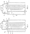
- Figure 1 illustrates a schematic cross sectional view of an embodiment of an electrochemical cell 100.
- the components of the electrochemical cell 100 may be contained at least partially in an associated housing 110.
- the cell 100 utilizes a liquid ionically conductive medium that is contained within the housing 110, and is configured to circulate therein to conduct ions within the cell 100. While at times the ionically conductive medium may be generally stationary within the housing 110, such as in a stagnant zone or other quantity of ionically conductive medium, it may be appreciated that the cell 100 may be configured to create a convective flow of the ionically conductive medium.
- such a flow may be generated through controlled direction of bubbles generated through electrochemical processes within the cell, through a sparger, or through any other bubble generating process.
- the flow may be generated through any other flow generator, including but not limited to a pump.
- localized heating causes convection of the liquid.
- the electrochemical cell 100 may be of any suitable structure or composition, including but not limited to being formed from plastic, metal, resin, or combinations thereof. Accordingly the cell 100 may be assembled in any manner, including being formed from a plurality of elements, being integrally molded, or so on. In various embodiments the cell 100 and/or the housing 110 may include elements or arrangements from one or more of U.S.
- the illustrated embodiment of Figure 1 schematically depicts in cross section a cell chamber 120 within the housing 110.
- the ionically conductive medium may generally be massed within the cell chamber 120, however may flow within the cell chamber 120, or may flow through the cell chamber 120 (e.g., from one electrochemical cell 100 to another electrochemical cell 100, or from a reservoir to and from the electrochemical cell 100).
- a fuel electrode 130 of the cell 100 may be supported in the cell chamber 120 so as to be contacted by the ionically conductive medium.
- the fuel electrode 130 is a metal fuel electrode that functions as an anode when the cell 100 operates in discharge (i.e., electricity generating) mode, as discussed in further detail below.
- the fuel electrode 130 may comprise a plurality of permeable electrode bodies 130a-130e. Although in the illustrated embodiment five permeable electrode bodies 130a-130e are used, in other embodiments any number is possible.
- Each permeable electrode body 130a-130e may include a screen that is made of any formation that is able to capture and retain, through electrodeposition, or otherwise, particles or ions of metal fuel from the ionically conductive medium that flows through or is otherwise present within the cell chamber 120.
- electrode body 130a may be a terminal electrode body, configured such that when charging, metal fuel may generally grow on the electrode bodies 130a-e in a direction defined from electrode body 130a towards electrode body 130e.
- the permeable electrode bodies 130a-130e may have different sizes so that a stepped scaffold configuration may be used, as described by United States Patent Application Serial No. 13/167,930 , in other embodiments the permeable electrode bodies 130a-130e may have substantially the same size.
- a plurality of spacers may separate the permeable electrode bodies 130a-130e so as to create flow lanes in the fuel electrode 130.
- the plurality of spacers may be connected to the housing 110 so that the fuel electrode 130 may be held in place relative to the housing 110
- the spacers may be molded in between the permeable electrode bodies 130a-130e, and potentially between the fuel electrode 130 and the charging electrode 140, such that the permeable electrode bodies 130a-e (and potentially the charging electrode 140) are part of a combined electrode module.
- Such a configuration is depicted in U.S. Patent Application Serial No. 12/901,410 , published as U.S. Patent Application Publication No. 2011/008627 8 .
- the spacers may be non-conductive and electrochemically inert so they are inactive with regard to the electrochemical reactions in the cell 100.
- the spacers may be made from a suitable plastic material, such as polypropylene, polyethylene, polyester, noryl, ABS, fluoropolymer, epoxy, or so on.
- the flow lanes in the fuel electrode 130 may be three-dimensional, and have a height that is substantially equal to the height of the spacers.
- the spacers would be oriented vertically so as to create flow lanes that are parallel to the charging electrode generating the bubbles, in other embodiments, such as but not limited to where the top of the fuel electrode 130 is blocked, as described below, the spacers may be oriented so as to create flow lanes oriented through the permeable electrode bodies 130a-e. It should be appreciated, however, that the spacers and/or flow lanes are optional, and may be omitted in some embodiments.
- a charging electrode 140 may be positioned spaced from the fuel electrode 130, distal from the terminal electrode body 130a (i.e. proximal to the electrode body 130e). In some embodiments, the charging electrode 140 may be a portion of the fuel electrode 130 (including, for example, being one or more of the permeable electrode bodies 130b-130e). As with the fuel electrode 130, the charging electrode 140 may be positioned within the cell chamber 120, so as to be in contact with the ionically conductive medium. In the illustrated embodiment, the charging electrode 140 is in a stepped configuration similar to the permeable electrode bodies 130a-e.
- the charging electrode 140 may extend at least as far as the longest of the permeable electrode bodies 130a-e, when those electrode bodies 130a-e are in a stepped scaffold configuration, or otherwise vary in size.
- the charging electrode 140 may be configured to participate in the oxidation of an oxidizable oxidant species, which is present in the liquid ionically conductive medium, so as to promote the reduction of an oxidized metal fuel species and growth of the metal fuel on the fuel electrode 130 during charging of the cell 100.
- the charging electrode 140 may be characterized as an oxygen evolving electrode, due to the bubbling off of oxygen gas from the charging electrode 140 during the charging of the electrochemical cell 1 00, as described in greater detail below.
- an oxidant reduction electrode 150 which is spaced from the fuel electrode 130 and the charging electrode 140, distal from the terminal electrode body 130a.
- the oxidant reduction electrode 150 may be sealed or otherwise assembled into an oxidant reduction electrode module 160 that is immersed into the ionically conductive medium in the cell chamber 120.
- At least one air channel 165 extends into the oxidant reduction electrode module 160, so as to provide air or another other oxidant to an air space 170 that is formed between a housing of the oxidant reduction electrode module 160 and the oxidant reduction electrode 150. It may be appreciated that the air or other oxidant in the air space 170 supplies oxidant to the oxidant reduction electrode 150. Additional details of such a configuration are described in U.S.
- the air channel 165 may include a tubular or similar configuration, which may facilitate supplying oxidant to the oxidant reduction electrode 150 while allowing ionically conductive medium to pass over the oxidant reduction electrode module 160 (e.g., to either side of the air channel 165).
- the air channel 165 may include a separate air channel inlet and air channel outlet extending into and out of the air space 170 respectively, allowing for the air channel 165 to form part of an air flow path through the air space 170.
- the air flow path is described in greater detail below. While the air inlet and air outlet may share a common housing extending through the ionically conductive medium into the oxidant reduction electrode module 160 in some embodiments, in other embodiments the air channel 165 may include a pair of spaced air paths extending through the ionically conductive medium into the oxidant reduction electrode module 160.
- the separate charging electrode 140 may be positioned between the oxidant reduction electrode 150 and the fuel electrode 130.
- the oxidant reduction electrode 150 may be utilized both during charging and discharging of the cell 100 (i.e. as an anode during charging and as a cathode during discharging).
- Components of the cell 100 including for example, the fuel electrode 130, the permeable electrode bodies 130a-e thereof, the separate charging electrode 140, and the oxidant reduction electrode 150 may be of any suitable construction or configuration, including, for example, being constructed from one or more of Nickel or Nickel alloys (including Nickel-Cobalt, Nickel-Iron, Nickel-Copper (i.e. Monel), or superalloys), Copper or Copper alloys, brass, bronze, carbon, platinum, silver, silver-palladium, or any other suitable metal or alloy.
- one or more components of the cell 100 such as the fuel electrode 130, the separate charging electrode 140, and the oxidant reduction electrode 150, may comprise a highly conductive material that is plated with a more degradation resistant material.
- the one or more components of the cell may comprise copper that is plated with nickel, tin, silver, gold, or any other chemically compatible material.
- the fuel electrode 130 may be formed from permeable metal screens (i.e. the permeable electrode bodies 130a-e), which may be configured to capture, retain, and provide a growth platform for the metal fuel.
- the separate charging electrode 140 may be of a similar configuration to one of the permeable electrode bodies 130a-e.
- the charging electrode 140 may be of another configuration, which may be configured to create a potential difference with the fuel electrode 130 so as to encourage fuel growth on the fuel electrode during charging of the electrochemical cell 100.
- the charging electrode 140 may be configured to evolve bubbles of gaseous oxygen during the charging process, which may rise upwards in the cell 100 due to their buoyancy in the ionically conductive medium, which may drive the convective flow of the ionically conductive medium.
- the oxidant reduction electrode 150 may too be of any appropriate construction or configuration.
- the oxidant reduction electrode 150 may generally be configured to provide for oxygen reduction in the electrochemical cell 100, to create a potential difference with the fuel electrode 130 during discharge of the cell 100.
- the oxidant reduction electrode 150 may contain an active layer having meshes or coatings which may be characterized as "active material(s)," that facilitate the electrochemical reactions.
- the oxidant reduction electrode 150 is positioned in the cell housing 110 such that the active materials contact the ionically conductive medium such that ions may be conducted therethrough, to and/or from the fuel electrode 130.
- the active materials may be formed by a mixture of catalyst particles or materials, conductive matrix and hydrophobic materials, sintered to form a composite material or otherwise layered together.
- the active materials may be constructed of one or more metals, such as but not limited to those listed above.
- the active materials may include a catalyst film, which in various embodiments may be formed by techniques including but not limited to thermal spray, plasma spray, electrodeposition, or any other particle coating method.
- Electrically coupled to the active materials may be a current collector, which may be configured to receive electrons from a load for consumption by the oxidant reduction reaction when the cell 100 is in a discharge mode.
- the current collector may be configured to collect electrons from the oxidation reaction at the active materials (i.e. if the oxidant reduction electrode 150 serves as the charging electrode) for delivery to the power supply PS, to participate in the electrochemical reactions at the active materials, when the cell 100 is in a charging mode.
- the current collector may be of any appropriate construction or configuration, including but not limited to being a metal screen, which may have gaps therein.
- the current collector may be constructed of metals or alloys such as but not limited to those described above for the active layer.
- hydrophobic may be any materials that are generally gas permeable but liquid impermeable, so as to contain the ionically conductive medium within the cell housing 110, or otherwise maintain an air space associated with the oxidant reduction electrode 150 (i.e. in the oxidant reduction electrode module 160).
- hydrophobic may in some contexts be understood as "water phobic" it should be appreciated that as used herein, hydrophobic implies that it resists permeation of or repels the ionically conductive medium as a whole, and not necessarily just the water in the ionically conductive medium. As such, the hydrophobic materials may also be considered hygrophobic, or "liquid phobic," materials.
- the oxidant reduction electrode 150 as a whole may therefore be liquid impermeable, yet permeable to a gaseous oxidant, such that the gaseous oxidant may contact the active materials of the oxidant reduction electrode 150, so as to serve as the oxidant during the electrochemical reactions taking place during discharge of the cell 100.
- the hydrophobic materials may be of any suitable construction or configuration that facilitates supporting the active materials thereon, be generally permeable to the gaseous oxidant, and be generally impermeable to the ionically conductive medium.
- the hydrophobic material or materials serve as a backing material for the active materials and/or the current collector.
- the hydrophobic materials may vary across embodiments, in some embodiments the hydrophobic materials may be constructed of or otherwise include a fluoropolymer.
- the hydrophobic materials may comprise polytetrafluoroethylene (also known as PTFE, or Teflon®), which may in some embodiments be thermo-mechanically expanded (also known as ePTFE, or Gore-Tex®).
- the hydrophobic materials may comprise Fluorinated Ethylene Propylene (also known as FEP), a fluoropolymer, or any other hydrophobic binder (e.g.
- the hydrophobic materials may have a fine pore size, such as but not limited to one on the order of less than 1 micrometer, or in more particular examples, may be on the order of approximately 50 to 200 nanometers. It may be appreciated that in some embodiments the hydrophobic materials may have limited tensile strength through the thickness of the oxidant reduction electrode 150. Accordingly, in some embodiments the hydrophobic materials may be reinforced by an oxidant-permeable reinforcing layer, such as that disclosed in U.S. Patent Application 13/668,180 , entitled “External PTFE Layer Reinforcement for Oxidant Electrode,” .
- the fuel electrode 130 may comprise any suitable fuel.
- the material selected as the metal fuel may be chemically reactive with a compatible ionically conductive medium and be more electro-positive than an active material at an opposing electrode (e.g. oxygen at an oxidant electrode in a metal-air cell).
- a backing of the fuel electrode may be permeable to fuel in the gas, liquid or vapor states (e.g. fuel is hydrogen, hydrocarbons, alcohols).
- fuel is hydrogen, hydrocarbons, alcohols.
- water is generated at the fuel electrode. It may be appreciated that a portion of the moisture generated at the fuel electrode could be recirculated to the air electrode.
- the moisture could be separated from the fuel via desiccant absorption on discharge, and during an idle state, water could be desorbed and fed to the air electrode.
- the ionic current via protons transports from the fuel electrode to the air electrode. The protons are hydrated during this, causing electro-osmotic drag leading to a lack of water at the fuel electrode. Accordingly, moisture could be recirculated from the air electrode exit to the fuel electrode inlet, using a scheme similar to the alkaline fuel cell example outlined above.
- the fuel used in the cell 100 may be a metal, such as iron, zinc, aluminum, magnesium, manganese, cadmium, lead, germanium, sodium or lithium.
- metal this term is meant to encompass all elements regarded as metals or semi-metals on the periodic table, including but not limited to alkali metals, alkaline earth metals, lanthanides, actinides, post-transition and transition metals, either in atomic, molecular (including metal hydrides), or alloy form when collected on the electrode body.
- the present invention is not intended to be limited to any specific fuel, and others may be used.
- the fuel may be provided to the cell 100 as particles suspended in the ionically conductive medium.
- the ionically conductive medium may be an aqueous solution.
- suitable mediums include aqueous solutions comprising sulfuric acid, phosphoric acid, triflic acid, nitric acid, potassium hydroxide, sodium hydroxide, sodium chloride, potassium nitrate, or lithium chloride.
- the ionically conductive medium may comprise an organic solvent, such as ethylene carbonate, dimethyl carbonate or other appropriate organic solvents, for example.
- the ionically conductive medium is aqueous potassium hydroxide.
- the ionically conductive medium may comprise an electrolyte.
- additives may be added to the ionically conductive medium, including but not limited to additives that enhance the electrodeposition process of the metal fuel on the fuel electrode 130, such as is described in U.S. Patent Application No. 13/028,496 and U.S. Patent Application No. 13/526,432 . Such additives may reduce the loose dendritic growth of fuel particles, and thus the likelihood of such fuel particles separating from the fuel electrode 130, for example.
- the ionically conductive medium may comprise any suitable separator or ion-exchange membrane, such as disclosed in U.S. Patent Application No. 13/526,342 .
- the fuel may be oxidized at the fuel electrode 130 when the fuel electrode 130 is operating as an anode, and an oxidizer, such as oxygen, Cl 2, , or any other appropriate oxidizer, may be reduced at the oxidant reduction electrode 150 when the oxidant reduction electrode 150 is operating as a cathode, which is when the cell 100 is connected to a load and the cell 100 is in discharge or electricity generation mode, as discussed in further detail below.
- the reactions that occur during discharge mode may generate by-product precipitates, e.g., a reducible fuel species, in the ionically conductive medium.
- zinc oxide may be generated as a by-product precipitate/reducible fuel species.
- the oxidized zinc or other metal may also be supported by, oxidized with or solvated in the electrolyte solution, without forming a precipitate (e.g. zincate may be a dissolved reducible fuel species remaining in the fuel).
- the reducible fuel species e.g., zinc oxide or zincate ions
- the fuel e.g., zinc, onto at least a portion of the fuel electrode 130 that functions as a cathode.
- either the oxidant reduction electrode 150 or the separate charging electrode 140, and/or another portion of the fuel electrode 130 functions as the anode, and oxidizes an oxidizable oxygen species (e.g., OH - ions) in the ionically conductive medium to evolve gaseous oxygen.
- the oxidizable oxygen species may be the reduced oxidant species that was created in the cell 100 during a discharge thereof.
- the oxidizer may be delivered to the oxidant reduction electrode 150 by a passive system, which may be sufficient to allow diffusion or permeation of, e.g. oxygen from the air, into the oxidant reduction electrode 150
- different sources of the oxidizer or mechanisms for bringing the oxidizer to the oxidant reduction electrode may be utilized.
- a pump such as an air pump AP may be used to deliver the oxidizer to the oxidant reduction electrode 150 under pressure.
- the air pump AP may be of any suitable construction or configuration, including but not limited to being a fan or other air movement device configured to produce a constant or pulsed flow of air or other oxidant.
- the oxidizer source may be a contained source of oxidizer.
- oxygen may be recycled from the electrochemical cell module 100, such as is disclosed in U.S. Patent Application 12/549,617 .
- the oxidizer source may be broadly regarded as the delivery mechanism, whether it is passive or active (e.g., pumps, blowers, etc.), by which the air is permitted to flow to the oxidant reduction electrode 150.
- the term "oxidizer source" is intended to encompass both contained oxidizers and/or arrangements for passively or actively delivering oxygen from ambient air to the oxidant reduction electrode 150.
- the species reduced at the cathode may be stored entirely within the electrochemical cell (e.g. in lead-acid or Ni-Cd cells).
- the permeable electrode bodies 130a-e, the separate charging electrode 140, and the oxidant reduction electrode 150 may be connected by a switching system that may be configured to connect the cell 100 to a power supply PS, a load, or other cells 100 in series.
- the fuel electrode 130 is connected to the load, and operates as an anode so that electrons given off by the metal fuel, as the fuel is oxidized at the fuel electrode 130, flows to the external load.
- the oxidant reduction electrode 150 functions as the cathode during discharge, and is configured to receive electrons from the external load and reduce an oxidizer that contacts the oxidant reduction electrode 150, specifically oxygen in the air surrounding the cell 100, oxygen being fed into the cell 100, or oxygen recycled from the cell 100.
- the operation of the switching system may vary across embodiments, and in some embodiments the operation may be similar to those described in U.S. Patent Application Serial No. 13/299,1 67 .
- the external load may be coupled to some of the permeable electrode bodies 130a-130e in parallel, as described in detail in United States Patent Application Serial No. 12/385,489 .
- the external load may only be coupled to the terminal permeable electrode body 130a, distal from the oxidant reduction electrode 150, so that fuel consumption may occur in series from between each of the permeable electrode bodies 130a-130e.
- the cell 100 may be configured for charge/discharge mode switching, as is described in United States Patent Application Serial No. 12/885,268, filed on September 17, 2010 .
- one or more of the electrode bodies 130a-e, the oxidant reduction electrode 150 and/or the charging electrode 140 may be interconnected by the switching system, or any other circuit, so as to selectively facilitate control of the charging and discharging of the cell 100.
- Switches associated with the switching system may be controlled by a controller, which may be of any suitable construction and configuration, including but not limited to, in some embodiments, conforming generally to those disclosed in U.S. Application Serial Numbers 13/083,929 , 13/230,549 , and 13/299,167 .
- the control of the switches of the switching system may be determined based on a user selection, a sensor reading, or by any other input.
- the controller may also function to manage connectivity between the load and the power source PS and a plurality of the cells 100.
- the controller may include appropriate logic or circuitry for actuating bypass switches associated with each cell 100 in response to detecting a voltage reaching a predetermined threshold (such as drop below a predetermined threshold).
- the ionically conductive medium may be filled to a level L within the cell chamber 120.
- a return inlet 180 may facilitate the addition of ionically conductive medium, or a component thereof (e.g., water) into the cell chamber 120, which may raise the level L of the ionically conductive medium.
- the return inlet 180 like the air channel 165, may be of a tubular configuration, configured so as to not block desired flow paths (if any) of the ionically conductive medium.
- Other configurations of the return inlet 180 are also possible, and may be present in various embodiments.
- the return inlet 180 may be at least partially molded into the cell housing 110. As described in greater detail below, in an embodiment at least a portion of the return inlet 180 may be configured to extend into the ionically conductive medium (e.g., into the cell chamber 120), and may help establish the level L of the ionically conductive medium. As shown in Figure 1 , a water management system WMS may be coupled between the air channel 165 and the return inlet 180, and may be configured to manage humidity levels within the air space 170, as well as recapture humidity as water, directing the water to the return inlet 180 to replenish the ionically conductive medium in the cell chamber 120. The water management system WMS is a feature of the present disclosure, and is described in greater detail below.
- the cell housing 110 is configured such that the oxidant reduction electrode 150 is immersed with the oxidant reduction electrode module 160 into the cell chamber 120
- the cell 100 is presented, whereby an oxidant reduction electrode 150* defines a boundary wall for the cell chamber 120, and is sealed to a portion of a housing 110* so as to prevent seepage of ionically conductive medium therebetween.
- a flow of the ionically conductive medium in the cell chamber 120 may be in a direction upwards and away from the oxidant reduction electrode 150*, across the top of the fuel electrode 130.
- such retrofitting of the electrochemical cell 100* may include surrounding the air facing side of the oxidant reduction electrode 150* by an external air chamber 190. While in the illustrated embodiment the external air chamber 190 is sealed to the cell housing 110*, in other embodiments the external air chamber 190 may be sealed to the oxidant reduction electrode 150*, or may be generally configured to generally surround the electrochemical cell 100*. Other configurations are also possible. It may further be appreciated that while the external air chamber 190 may be sealed to portions of the electrochemical cell 100* in some embodiments, in other embodiments the external air chamber 190 may more simply abut the electrochemical cell 100*, or more loosely be secured to the electrochemical cell 100*.
- the external air chamber 190 forms an air space 170 between the oxidant reduction electrode 150* and the walls of the external air chamber 190.
- an air channel 165 may extend from the external air chamber 190, so as to form a path for air to flow between the air space 170 and the water management system WMS.
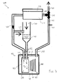
- Figure 3 schematically illustrates an embodiment of a water management system 200. It may be appreciated that the water management system 200 may be utilized as the water management WMS in the embodiments of Figures 1 and 2 .
- Figure 3 also generally illustrates a representation of the electrochemical cell 100.
- the cell housing 110 defines a cell chamber 120 that contains an amount of ionically conductive medium filled to the level L.
- the fuel electrode 130 and the separate charging electrode 140 are immersed in the ionically conductive medium.
- the oxidant reduction electrode 150 is also immersed in the ionically conductive medium, sealed to the oxidant reduction electrode module 160 to maintain the air space 170 therein.
- the air channel 165 includes an air channel inlet 210 and an air channel outlet 220.
- a flow of air comprising an oxidant may be received from an external source (e.g., ambient air, or a contained oxidant source), and may be fed into the air space 170 through the air channel inlet 210, before flowing out of the air channel outlet 220, as discussed in greater detail below.
- an external source e.g., ambient air, or a contained oxidant source
- the air channel inlet and the air channel outlet are shown to be spaced differently relative to the oxidant reduction electrode 150 in the schematic view of Figure 3 , it may be appreciated that such an illustration may be simply to schematically show movement of the flow, and the air channel inlet 210 and the air channel inlet 220 may be aligned with one another in a plane parallel to that of the oxidant reduction electrode 150 in some embodiments.
- the water management system 200 of Figure 3 may be discussed in terms of the flows of air therein. In embodiments where another gas phase is carrying the water or humidity content, it may be understood that the flow might be of the other gas phase.
- an air inlet 230 may receive air from outside of the electrochemical cell 100 and the water management system 200. While in some embodiments the air may be from the ambient air in the atmosphere outside of the water management system 200, in other embodiments the air may be from a contained oxidizer source (e.g., a tank of pure oxygen or an oxygen mix). In some embodiments, such as that illustrated where the air is from surrounding atmosphere, the air inlet 230 may include an air filter or other filtering structure configured to remove particulates or other contaminants from the air.
- the water management system 200 may include a fan 240 or other air flow generator positioned to generate a flow of the air from the air inlet 230 to the air channel inlet 210 of the air channel 165 associated with the oxidant reduction electrode 150.
- the air entering the air inlet 230 may be generally dry relative to air inside the air space 170. This may be because the oxidant reduction electrode 150, immersed into and in contact with the ionically conductive medium in the cell chamber 120, may be somewhat porous. Although hygrophobic coatings and other mechanisms may attempt to prevent the ionically conductive medium from permeating the oxidant reduction electrode 150, it may be appreciated that water (e.g. water vapor) from the ionically conductive medium may still slowly pass through the oxidant reduction electrode 150, increasing the humidity of the air in the air space 170.
- water e.g. water vapor
- osmotic forces may cause water to permeate through from an ionically conductive medium contacting side of the oxidant reduction electrode 150 to an air side of the oxidant reduction electrode. Such permeation may occur more commonly when the relative humidity in the air space is low (i.e., approximately 10%).
- the air flow may exit the oxidant reduction electrode module 160 via the air channel outlet 220.
- the relative humidity of the air flow beyond the air channel outlet 220 may vary, in some embodiments the relative humidity leaving the air space 170 may be approximately 70%. It may be appreciated that a portion of the air flow may be redirected towards the air inlet 230 via an air recirculator 250.
- the air recirculator 250 connects the air channel outlet 220 back to the air channel inlet 210, such as at a point upstream of the fan 240.
- the air recirculator 250 may direct the portion of the air flow between the air inlet 230 and the fan 240, so that some of the humid air mixes with the relatively drier air entering the air inlet 230, other configurations are alternatively possible.
- the air recirculator 250 may be configured to increase the relative humidity of the ambient air entering the air inlet 230 to approximately 30%, for example, by mixing a portion of the humid air (e.g., at approximately 70%) with the relatively dry air (e.g., ambient air at approximately 10%). As such, the air that continues through the air channel inlet 210 into the air space 170 would have some humidity therein that is greater than the drier ambient air outside of the electrochemical cell 100 and the water management system 200.
- recirculation of some of the humidity from the air space 170 may be beneficial to the performance and lifespan of the oxidant reduction electrode 150.
- the recirculation may prevent the air in the air space 170, especially at the air channel inlet 210, from becoming too dry. Excessively dry air at the air side of the oxidant reduction electrode 150 may increase a rate at which water from the ionically conductive medium succumbs to osmotic forces and escapes through the oxidant reduction electrode 150 into the air space 170. As more water escapes, the concentration of the ionically conductive medium in the oxidant reduction electrode 150 increases.
- the increased concentration may further increase the osmotic pressure in the oxidant reduction electrode 150, as lower concentrated ionically conductive medium from the cell chamber 120 may try to dilute the higher concentration in the oxidant reduction electrode 150.
- the oxidant reduction electrode 150 may be more susceptible to structural degradation including blistering, delamination or even rupture, which may cause loss of electrical contact and/or a leak of the ionically conductive medium that could fill the air space 170 and render the electrochemical cell 100 partially or wholly inoperative.
- valve 260 may be located anywhere in the air flow path beyond where the air flow branches to the air recirculator 250, and in some embodiments the valve 260 may be located within the desiccator unit 270.
- valve 260 may be of any appropriate construction or configuration, and in some embodiments may comprise a check valve or a reed valve, and may be simply configured to prevent undesired backflow. The operation of some embodiments of the valve 260 (e.g., when it is selectively opened and closed) is discussed in greater detail below.
- the desiccator unit 270 may also be of any appropriate construction or configuration, and is configured to selectively capture and release water from the humid air that has passed through the valve 260.
- the desiccator unit 270 comprises a chamber having a desiccant therein. While in an embodiment the desiccator unit 270 comprises silica gel, other hygroscopic substances may alternatively be utilized to absorb water from the humid air.
- the desiccator unit 270 may comprise activated charcoal, aluminum oxide, calcium sulfate, calcium chloride, montmorillonite clay and/or a molecular sieve. Other constructions or configurations that have exothermic water adsorption and endothermic water desorption properties may additionally or alternatively be utilized.
- the desiccator unit may comprise a solar still, shaped to condense and isolate water from the air therein.
- a passively or actively cooled condensing unit could be employed.
- active cooling could be accomplished by a Peltier/thermoelectric element.
- the desiccator unit 270 is configured to absorb and store the water from the humid air in a desiccant, it may be appreciated that the water may be selectively released by heating the desiccant.
- the desiccator unit 270 comprises a heater 275 which may be selectively activated to heat the desiccant.
- the desiccator unit 270 may be shaped with an angled base leading to the outflow path 280.
- the heater 275 may be configured to heat the water sufficient to turn the water to steam, and direct the steam to the outflow path 280.
- a selector valve 290 may be configured to selectively connect the outflow path 280 to either an air outlet 300 or to a return conduit 310 that extends to the return inlet 180 of the electrochemical cell 100. It may be appreciated that the selector valve 290 of the illustrated embodiment is merely exemplary, and a plurality of valves and paths that selectively couple the desiccator unit 270 to the air outlet 300 and the return inlet 180 may be utilized in other embodiments. In some embodiments, the selector valve 290 may typically be positioned to close off the return conduit 310 to prevent evaporation of water from the cell's ionically conductive medium therethrough.
- the selector valve 290 may also be positioned to open the return conduit 310 and optionally close the air outlet 300 when the desiccator unit 270 is being used to release water for return to the ionically conductive medium.
- the selector valve 290 may be configured to connect the air outlet 300 to the return inlet 180, which may facilitate utilizing the air outlet 300 as an external liquid inlet, so that a technician may utilize the air outlet 300 to pour ionically conductive medium into the cell chamber 120, or pour additional water so as to dilute a concentration of ionically conductive medium and/or to adjust desired electrolyte level.
- thermocouple 320 may be positioned in the return conduit 310 so as to contact water or steam flowing through the return conduit 310.
- thermocouple 320 may be situated within the desiccator unit 270.
- a plurality of thermocouples may be suitable.
- the thermocouple 320 may detect the increased temperature of the water, heated by the heater 275, over a baseline temperature of ambient air within the return conduit 310. When the water no longer flows across the thermocouple 320, the thermocouple may detect the decrease in temperature, and turn off the heater 275 in response.
- thermocouple 320 may operate in a similar manner by turning off the heater 275 when the temperature drops, indicating that water is no longer being directed back into the cell chamber 120.
- the thermocouple 320 may also be coupled to a control for the selector valve 290, and may be configured to modify a configuration of the selector valve 290 once water ceases to flow, in conjunction with operating the heater 275.
- the operation of the electrochemical cell 100 may modify operation of the water management system 200.
- the water management system 200 may operate differently when the electrochemical cell 100 is in a discharge mode than when the electrochemical cell 100 is in a recharge mode.
- a potential difference may be formed between the fuel electrode 130 and the oxidant electrode 150, such that the metal fuel on the fuel electrode 130 is being oxidized, while an oxidant (e.g., the oxygen in the air being received in the air inlet 230) is being reduced at the oxidant reduction electrode 150.
- air recirculator 250 comprises an adjustable valve.
- an air recirculator valve may be adjusted depending on local climate, (e.g. relative humidity) or any other suitable metric.
- the selector valve 290 may be opened to the atmosphere (e.g., the outflow path 280 is open to the air outlet 300, so that as the humidity is being absorbed from the humid air in the desiccator unit 270, the dried air may vent to the atmosphere.
- the desiccator unit 270 may therefore absorb moisture originally from the ionically conductive medium that would otherwise escape to the atmosphere through the oxidant reduction electrode 150, causing evaporation, and thus increased concentration, of the ionically conductive medium.
- oxygen ions may be oxidized to evolve gaseous oxygen the separate charging electrode 140 and/or a portion of the fuel electrode 130, while fuel ions may be reduced at least at another portion of the fuel electrode 130, to plate metal fuel on at least that other portion of the fuel electrode 130.
- the valve 260 may be closed (as the oxidant reduction electrode 150 may be idle), and the heater 275 may be heating the desiccator unit 270 to release water therefrom. It may be appreciated that by closing the valve 260, water from the desiccator unit 270 may be prevented from being released (e.g., as steam) out of the air recirculator 250 and/or the air inlet 230.
- the selector valve 290 may be closed to the atmosphere (and the air outlet 300), and instead may be open between the outflow path 280 and the return conduit 310.
- the heated water may be directed through the return conduit 310 to the return inlet 180, condensing on the surface of the ionically conductive medium, or otherwise recombining with the ionically conductive medium.
- the heated water e.g., steam
- the thermocouple 320 it may be understood that the moisture absorbed in the desiccator unit 270 has been released back into the ionically conductive medium, and the heater 275 may be deactivated.
- multiple electrochemical cells may share a common water management system. It may be appreciated that such a water management system may be configured so as to ensure that each of the electrochemical cells associated therewith maintain desired amounts of ionically conductive medium therein.
- FIG 4 schematically illustrates a water management system 330 configured for use with both electrochemical cell 100a and electrochemical cell 100b. As discussed below, it may be appreciated that additional electrochemical cells 100 may be utilized in other embodiments. Further, other electrochemical cells (e.g., electrochemical cells 100*) may additionally or alternatively be utilized in other embodiments. It may be appreciated that components of the water management system 330 may be generally similar to those utilized in the water management system 200, and as such, like elements may be labeled similarly.
- the air inlet 230, the fan 240, the valve 260, the desiccator unit 270, the heater 275, and the thermocouple 320 may perform similar functions and be of similar configurations to those discussed above in water management system 200.
- both electrochemical cell 100a and electrochemical cell 100b are configured with fuel electrodes 130, and charging electrodes 140 immersed in ionically conductive medium in cell chambers 120, that are defined by cell housings 110.
- the cell chamber 120a is associated with electrochemical cell 100a
- the cell chamber 120b is associated with electrochemical cell 100b.
- oxidant reduction electrodes 150 are immersed in the ionically conductive medium, and are sealed to oxidant reduction electrode modules 160, which are configured to maintain air spaces 170 therein.
- air space 170a is found in electrochemical cell 100a
- air space 170b is found in electrochemical cell 100b.
- the air spaces 170a and 170b are associated with air channels 165a and 165b extending into and out of electrochemical cells 100a and 100b respectively.
- the water management system 330 may be configured to receive air comprising an oxidant via the air inlet 230.
- a flow of the air may be generated by the fan 240, which may be directed to each of the electrochemical cells 100a-b.
- the air flow may be distributed by an inlet air manifold 340. While the schematically illustrated inlet air manifold 340 is configured to distribute the air flows to air channel inlets 210a and 210b of the air channels 165a and 165b respectively, in other embodiments additional cells may also receive inflows of air from the inlet air manifold 340.
- the air flows may absorb moisture in the air spaces 170a and 170b, and exit the immersed oxidant electrode modules 160 via the air channel outlets 220a and 220b respectively.
- the air flows of the humid air may recombine at an exit air manifold 350 of the water management system 330. While the exit air manifold 350 of the illustrated embodiment couples to electrochemical cells 100a and 100b, additional electrochemical cells 100 (or other configurations of electrochemical cells) may additionally or alternatively be coupled to the exit air manifold 350 in other embodiments.
- the air recirculator 250 may be a separate line extending from the exit air manifold 350. It may be appreciated that such a configuration may decrease a pressure buildup associated with the air flows. Again, the air recirculator 250 may direct some of the humid air back towards the air inlet 230, so as to prevent the air in the air spaces 170a and 170b from becoming excessively dry.
- a main humid air channel 360 may therefore extend between the exit air manifold 350 and the desiccator unit 270, and may facilitate capture of the moisture from the humid air received from the exit air manifold 350 by the desiccator unit 270.
- the valve 260 preventing backflows of steam when the heater 275 is heating the desiccator unit 270 may be located in the main humid air channel 360 in some embodiments.
- an air outflow path 370 having an associated air outflow valve 380, may facilitate selective release of dry/spent air (e.g., when the electrochemical cell is operating in a discharge mode).
- the return conduit 310 extends directly from the desiccator unit 270 to a vapor distribution manifold 390.
- the vapor distribution manifold 390 may couple to the return inlets 180 (individually, the return inlet 180a associated with electrochemical cell 100a, and the return inlet 180b associated with the electrochemical cell 100b), to facilitate the return of the captured water back into the cell chambers 120a and 120b respectively. While the vapor distribution manifold 390 of the illustrated embodiment couples to electrochemical cells 100a and 100b, additional electrochemical cells 100 (or other configurations of electrochemical cells) may additionally or alternatively be coupled to the vapor distribution manifold 390 in other embodiments.
- the water management system 330 may be configured to vary in operation depending on whether the electrochemical cells 100 are in charge mode or discharge mode.
- the electrochemical cells 100 may be configured to each be in a charge mode at a same time, so that the water management system 330 may vary in operation to cooperate with the set of electrochemical cells 100.
- the water management system 330 may include additional valves associated with each of the electrochemical cells 100, which may individually be controlled to open and close to facilitate charge mode operation and discharge mode operation in the water management system 330 for each of the electrochemical cells 100.
- air when the electrochemical cells 100 are in a discharge mode, air may enter the air inlet 230, and a flow may be generated through the fan 240.
- the flow may be divided by the inlet air manifold 340, so as to establish an air flow to the air space 170a and the air space 170b respectively.
- the air flow may exit the air channel outlets 220a and 220b, and recombine at the exit air manifold 350.
- a portion of the humid air may be recirculated to the air inlet 230 by the air recirculator 250, while the remainder of the humid air may pass through the main humid air channel 360 (and the valve 260), into the desiccator unit 270.
- the humidity may be absorbed from the air flow in the desiccator unit 270, and the dried air may exit through the air outflow path 370 (with the air outflow valve 380 opened to allow venting of the dried flow into the atmosphere).
- the heater 275 may be activated to free water absorbed in the desiccator unit 270.
- the valve 260 may be closed to prevent a flow of water or vapor back into the air spaces 170a and 170b, and the air outflow valve 370 may be closed to prevent venting of water or vapor out of the water management system 330 and the electrochemical cells 100.
- the closure of the valve 260 may be automatic where the valve 260 is a one-way valve configured to prevent backflow (e.g., a reed valve).
- water vapor may proceed through the return conduit 310 and the vapor distribution manifold 390, towards the return inlets 180a and 180b associated with each of the electrochemical cell 100. Again, heating by the heater 275 may cease once the thermocouple 320, or another sensor, determines that no more water is proceeding through the return conduit 310 back toward the cell chambers 120a and 120b, as discussed in greater detail below.
- charging of the electrochemical cells 100 may be configured to disengage the fan 240, while in other embodiments the fan 240 may remain engaged to cycle the humid air through the air recirculator 250.
- the operation of the fan 240 may be pulsed or otherwise intermittent, while in other embodiments the fan 240 may operate continuously. Further, operation of the fan 240 may be controlled through timing circuits, control logic associated with the electrochemical cells 100 (or a man controller associated therewith), and/or through sensors associated with the water management system 330. Other configurations are also possible in other embodiments.
- the heater 275 may be activated so as to release water vapor towards the return inlets 180a and 180b.
- the released water may be pressurized.
- the released water, under pressure, may then be directed through the return conduit 310 towards the electrochemical cells 100.
- the return inlets 180a and 180b may facilitate self-leveling of the ionically conductive medium.
- the heater 275 is configured to release the water from the desiccator unit 270 in vapor form
- the water vapor prevented from backflow by the valve 260, and escaping the water management system to the outside air by the air outlet valve 380, would be forced to flow through the return conduit 310 towards the return inlets 180a and 180b.
- no valves are utilized between the desiccator unit 270 and the electrochemical cells 100, as flow of water in vapor/steam form is balanced through regulation of pressure heads at the return inlets 180a and 180b.
- the amount of the extension may define a desired minimum level for the ionically conductive medium. Accordingly, where the level of the ionically conductive medium is sufficient to close the return inlets 180a and 180b, then the water vapor may create a head pressure and some back pressure where it meets the ionically conductive medium. Back pressure at one electrochemical cell 100 may cause backflow of the water vapor to another electrochemical cell 100, which may have a level of ionically conductive medium that is below the level established by the return inlet 180. As such, the vapor would condense at the other electrochemical cell 100, refilling that cell chamber 120 instead of overfilling the cell chamber 120 of the electrochemical cell 100 that has sufficient ionically conductive medium.
- a level L a of ionically conductive medium in the electrochemical cell 100a is higher relative to a level L b of ionically conductive medium in the electrochemical cell 100b.
- the level L b of ionically conductive medium in the electrochemical cell 100b is below the return inlet 180b, while the level L a of ionically conductive medium in the electrochemical cell 100a is at or above the furthest extent of the return inlet 180a.
- the water vapor generated by the heater 275 traversing along the return inlet 180a may cause head pressure and back pressure where it meets the ionically conductive medium.
- head pressure may establish a level L a(2) of ionically conductive medium within the return inlet 180a
- associated back pressure would result in the water vapor preferentially traversing the path of least resistance (e.g., the return inlet 180b), and condensing in the cell chamber 120b to raise the level L b .
- the head pressures and back pressures associated with cell chambers 120 having at least a minimum desired level of ionically conductive medium would not cause those electrochemical cells 100 to overflow, but rather would fill cell chambers 120 having less than the minimum desired level of ionically conductive medium, to achieve self-leveling across a plurality of electrochemical cells 100.
- the electrochemical cells 100 may contain therein level sensors 400 (individually level sensors 400a and 400b) configured to ascertain a level of the ionically conductive medium.
- the level sensors 400a and 400b may be of any construction or configuration, including but not limited to a buoyancy/float sensor, an optical sensor, a thermal sensor, conductivity sensor or so on.
- the heater 275 may be activated (with the valves 260 and 380 closed), to release water from the desiccator unit 270.
- refilling may be automatic, based on timer circuits or similar control mechanisms.
- sensors associated with the desiccator unit 270 may determine when to activate the heater 275. As one non-limiting example, if a sensor determines that the desiccant is completely saturated, however a humidity level within the desiccator unit 270 rises (indicating that additional water is unable to be absorbed in the desiccant), the heater 275 may vaporize the water to attempt to replenish the cell chambers 120. Other configurations are also possible, and may vary across embodiments.
- the desiccator unit 270 may selectively open to the atmosphere, so that the desiccator unit 270 may capture and retain atmospheric moisture, or may be configured to receive air from some other external source, rather than from the air leaving the air channel from the cell.
- this arrangement may be more suitable for electrochemical cells which do not comprise an air breathing electrode.
- the desiccator unit 270 may selectively close off a path from the air channel outlets 220 of the electrochemical cells 100 (e.g., by closing the valve 260) so that humid air from the air channel outlets 220 is not inadvertently lost to the atmosphere when the desiccator unit 270 is extracting humid air from the atmosphere.
- the opening to the atmosphere may similarly be closed off via the valve 260, or another valve, when the heater 275 is heating the desiccator unit 270 to release the extracted water, so that the extracted water is directed through the return conduit 310.
- water management systems such as the water management system 200 or 330, might not be generally configured to capture the humidity from the electrochemical cells 100.
- the opening to the atmosphere might be the main or sole source of humid air for the desiccator unit 270 to capture humidity for subsequent release into the electrochemical cells 100.
- the humid air may simply remain in the air spaces 170, may be circulated through the air recirculator 250, or may be otherwise vented to the atmosphere.
- valves are passive, requiring no external control for operation.
- active valves having an external means of actuation may be employed.
- the valves utilized herein may be of any appropriate configuration, including but not limited to three-way valves, reed valves, bimetal snap check valves, or so on.
- the valves may be activated through any appropriate source, including but not limited to servos, electronic controllers, heat (e.g., from the heater 275) or pressure (e.g., from the air flow generated by the fan 240 or from pressure associated with the heated water vapor).
- manifolds, pipes, tubes, connections, or other air/water flow paths may be of any appropriate construction or configuration, including but not limited to metal, plastic, and/or rubber.
- Other components of the electrochemical cells (e.g., electrochemical cell 100) or the water management systems (e.g., water management system 330) may similarly be of varied constructions or configurations.
Landscapes
- Chemical & Material Sciences (AREA)
- Chemical Kinetics & Catalysis (AREA)
- Engineering & Computer Science (AREA)
- General Chemical & Material Sciences (AREA)
- Manufacturing & Machinery (AREA)
- Electrochemistry (AREA)
- Sustainable Development (AREA)
- Sustainable Energy (AREA)
- Life Sciences & Earth Sciences (AREA)
- Analytical Chemistry (AREA)
- Oil, Petroleum & Natural Gas (AREA)
- Fuel Cell (AREA)
- Hybrid Cells (AREA)
- Electrolytic Production Of Non-Metals, Compounds, Apparatuses Therefor (AREA)
- Water Treatment By Electricity Or Magnetism (AREA)
Applications Claiming Priority (2)
| Application Number | Priority Date | Filing Date | Title |
|---|---|---|---|
| US201361763423P | 2013-02-11 | 2013-02-11 | |
| PCT/US2014/015613 WO2014124386A1 (en) | 2013-02-11 | 2014-02-10 | Water recapture/recycle system in electrochemical cells |
Publications (3)
| Publication Number | Publication Date |
|---|---|
| EP2954583A1 EP2954583A1 (en) | 2015-12-16 |
| EP2954583A4 EP2954583A4 (en) | 2016-09-28 |
| EP2954583B1 true EP2954583B1 (en) | 2018-04-04 |
Family
ID=51297646
Family Applications (1)
| Application Number | Title | Priority Date | Filing Date |
|---|---|---|---|
| EP14749407.4A Active EP2954583B1 (en) | 2013-02-11 | 2014-02-10 | Water recapture/recycle system in electrochemical cells |
Country Status (11)
| Country | Link |
|---|---|
| US (2) | US10320014B2 (ja) |
| EP (1) | EP2954583B1 (ja) |
| JP (1) | JP6316322B2 (ja) |
| CN (1) | CN105144449B (ja) |
| AU (1) | AU2014214641B2 (ja) |
| BR (1) | BR112015018963A2 (ja) |
| CA (1) | CA2900867A1 (ja) |
| ES (1) | ES2666420T3 (ja) |
| MX (1) | MX2015010380A (ja) |
| WO (1) | WO2014124386A1 (ja) |
| ZA (1) | ZA201505831B (ja) |
Cited By (6)
| Publication number | Priority date | Publication date | Assignee | Title |
|---|---|---|---|---|
| US11394035B2 (en) | 2017-04-06 | 2022-07-19 | Form Energy, Inc. | Refuelable battery for the electric grid and method of using thereof |
| US11552290B2 (en) | 2018-07-27 | 2023-01-10 | Form Energy, Inc. | Negative electrodes for electrochemical cells |
| US11611115B2 (en) | 2017-12-29 | 2023-03-21 | Form Energy, Inc. | Long life sealed alkaline secondary batteries |
| US11664547B2 (en) | 2016-07-22 | 2023-05-30 | Form Energy, Inc. | Moisture and carbon dioxide management system in electrochemical cells |
| US11949129B2 (en) | 2019-10-04 | 2024-04-02 | Form Energy, Inc. | Refuelable battery for the electric grid and method of using thereof |
| US11973254B2 (en) | 2018-06-29 | 2024-04-30 | Form Energy, Inc. | Aqueous polysulfide-based electrochemical cell |
Families Citing this family (11)
| Publication number | Priority date | Publication date | Assignee | Title |
|---|---|---|---|---|
| DE102014018231A1 (de) * | 2014-12-04 | 2016-06-09 | Mann + Hummel Gmbh | Akkumulator-Anordnung für ein Fahrzeug |
| EP3396740B1 (en) | 2015-03-19 | 2020-06-17 | NantEnergy, Inc. | Electrochemical cell comprising an electrodeposited fuel |
| ES2727794T3 (es) | 2015-03-30 | 2019-10-18 | Nantenergy Inc | Sistema de gestión de agua en celdas electroquímicas con retorno de vapor que comprende electrodos de aire |
| US10246240B1 (en) * | 2015-12-22 | 2019-04-02 | Terra Universal, Inc. | Dry purge desiccator and method |
| US10386084B2 (en) * | 2016-03-30 | 2019-08-20 | Xergy Ltd | Heat pumps utilizing ionic liquid desiccant |
| FI128437B (en) * | 2016-08-18 | 2020-05-15 | Tm System Finland Oy | Method and arrangement for air recirculation in the drying process |
| CN107014077A (zh) * | 2017-06-13 | 2017-08-04 | 合肥美的暖通设备有限公司 | 一种热泵热水机 |
| KR102651548B1 (ko) * | 2018-11-07 | 2024-03-28 | 삼성전자주식회사 | 금속-공기 전지 및 금속-공기 전지의 작동방법 |
| CN111943296B (zh) * | 2020-07-30 | 2021-12-14 | 中国科学技术大学 | 燃料电池余能与吸收式水生成器耦合的淡水-电联供系统 |
| CN114497639B (zh) * | 2021-12-24 | 2023-10-20 | 重庆明天氢能科技有限公司 | 一种提高燃料电池系统绝缘电阻的方法 |
| US12080920B1 (en) * | 2023-12-07 | 2024-09-03 | David C. Marconi | Automatic battery watering system |
Family Cites Families (47)
| Publication number | Priority date | Publication date | Assignee | Title |
|---|---|---|---|---|
| US3363570A (en) * | 1965-08-23 | 1968-01-16 | Universal Oil Prod Co | Tank filling system |
| US4386141A (en) | 1982-02-22 | 1983-05-31 | Exide Corporation | Watering device for batteries |
| US5284176A (en) | 1992-06-30 | 1994-02-08 | Flow-Rite Controls, Ltd. | Battery refill system |
| US5453334A (en) | 1995-01-06 | 1995-09-26 | Ford Motor Company | Automatic battery watering system |
| US6164309A (en) | 1997-03-13 | 2000-12-26 | Trojan Battery Company | Liquid filling device |
| US6786226B2 (en) | 2000-04-10 | 2004-09-07 | Club Car, Inc. | Battery fluid supply system |
| US6869709B2 (en) * | 2002-12-04 | 2005-03-22 | Utc Fuel Cells, Llc | Fuel cell system with improved humidification system |
| US7040431B2 (en) | 2003-08-18 | 2006-05-09 | Daimlerchrysler Corporation | Fuel cell hybrid vehicle with automatically watered aqueous batteries |
| US20050142398A1 (en) * | 2003-12-24 | 2005-06-30 | General Electric Company | Prevention of chromia-induced cathode poisoning in solid oxide fuel cells (SOFC) |
| US7556056B2 (en) | 2005-03-03 | 2009-07-07 | Liquid Precision, Inc. | Single point battery watering system with pivot float and ball valve |
| DE602006015950D1 (de) | 2005-05-28 | 2010-09-16 | Aerovironment Inc | Pegelkontrollsystem für ein batterieelektrolyt |
| US8007943B2 (en) * | 2005-11-03 | 2011-08-30 | GM Global Technology Operations LLC | Cascaded stack with gas flow recycle in the first stage |
| CN2888658Y (zh) * | 2005-11-04 | 2007-04-11 | 胜光科技股份有限公司 | 具操作参数调节能力的燃料电池装置 |
| US7829236B2 (en) * | 2005-12-14 | 2010-11-09 | Daimler Ag | Hydration sensor apparatus for measuring membrane hydration in a fuel cell stack |
| US8241796B2 (en) * | 2006-03-07 | 2012-08-14 | Afc Energy Plc | Electrodes of a fuel cell |
| GB0604597D0 (en) * | 2006-03-07 | 2006-04-19 | Dfc Energy Ltd | A fuel cell assembly |
| TWI291367B (en) * | 2006-06-09 | 2007-12-21 | Bossmen Inc | Air drying device for air dryer |
| US20090239131A1 (en) * | 2007-01-16 | 2009-09-24 | Richard Otto Winter | Electrochemical energy cell system |
| JP2008251491A (ja) | 2007-03-30 | 2008-10-16 | Equos Research Co Ltd | 燃料電池システム |
| US8168337B2 (en) | 2008-04-04 | 2012-05-01 | Arizona Board Of Regents For And On Behalf Of Arizona State University | Electrochemical cell, and particularly a metal fueled cell with non-parallel flow |
| US8309259B2 (en) | 2008-05-19 | 2012-11-13 | Arizona Board Of Regents For And On Behalf Of Arizona State University | Electrochemical cell, and particularly a cell with electrodeposited fuel |
| JP2008277315A (ja) | 2008-08-22 | 2008-11-13 | Casio Comput Co Ltd | 電子機器 |
| US20100055508A1 (en) | 2008-08-27 | 2010-03-04 | Idatech, Llc | Fuel cell systems with water recovery from fuel cell effluent |
| US8491763B2 (en) | 2008-08-28 | 2013-07-23 | Fluidic, Inc. | Oxygen recovery system and method for recovering oxygen in an electrochemical cell |
| US20100316935A1 (en) | 2008-12-05 | 2010-12-16 | Fluidic, Llc | Electrochemical cells connected in fluid flow series |
| BRPI1014534B1 (pt) | 2009-05-11 | 2020-06-30 | Arizona Board Of Regents Acting For And On Behalf Of Arizona State University | célula eletroquímica de metal-ar a baixa temperatura e método de operar uma célula eletroquímica de metal-ar |
| US8852819B2 (en) * | 2009-06-05 | 2014-10-07 | Blackberry Limited | System and method for managing fuel cell operating conditions in a mobile communication device |
| GB0916179D0 (en) | 2009-09-16 | 2009-10-28 | Smith Rachel L | Coaxial device |
| JP5521044B2 (ja) | 2009-09-18 | 2014-06-11 | フルイディック,インク. | 充電極を備え,セル内で充電モードと放電モードとを切り替える充電式電気化学セルシステム |
| US8492052B2 (en) | 2009-10-08 | 2013-07-23 | Fluidic, Inc. | Electrochemical cell with spacers for flow management system |
| KR100992716B1 (ko) * | 2009-10-13 | 2010-11-05 | 석상엽 | 접촉 비표면적을 증대시킨 유가금속 회수용 전해조 |
| US8877391B2 (en) | 2010-02-16 | 2014-11-04 | Fluidic, Inc. | Electrochemical cell, and particularly a cell with electrodeposited fuel |
| EP2369657B1 (en) | 2010-03-23 | 2014-12-24 | Jones, William E. M. | Battery watering system |
| EP2559097B1 (en) | 2010-04-13 | 2018-05-30 | Fluidic, Inc. | Metal-air electrocemical cell with high energy efficiency mode |
| JP5511481B2 (ja) | 2010-04-19 | 2014-06-04 | 日本電信電話株式会社 | 電源システムおよび電源運転方法 |
| ES2620238T3 (es) | 2010-06-24 | 2017-06-28 | Fluidic, Inc. | Celda electroquímica con ánodo de combustible de andamio escalonado |
| WO2012012364A1 (en) | 2010-07-19 | 2012-01-26 | Fluidic, Inc. | Electrochemical cell with catch tray |
| CN202550031U (zh) | 2010-09-16 | 2012-11-21 | 流体公司 | 具有渐进析氧电极/燃料电极的电化学电池系统 |
| JP5908251B2 (ja) | 2010-11-17 | 2016-04-26 | フルイディック,インク.Fluidic,Inc. | 階層型アノードのマルチモード充電 |
| CN202737060U (zh) | 2011-02-04 | 2013-02-13 | 流体公司 | 用于离子导电介质的分散系统、电化学电池系统和外壳 |
| EP2721686B1 (en) | 2011-06-17 | 2018-11-28 | NantEnergy, Inc. | Ionic liquid containing sulfonate ions |
| WO2012174558A1 (en) | 2011-06-17 | 2012-12-20 | Fluidic, Inc. | Metal-air cell with ion exchange material |
| US9214708B2 (en) | 2011-08-05 | 2015-12-15 | Fluidic, Inc. | Gas vent for electrochemical cell |
| US8906563B2 (en) | 2011-11-04 | 2014-12-09 | Fluidic, Inc. | Internal convection cell |
| US9444105B2 (en) | 2011-11-04 | 2016-09-13 | Fluidic, Inc. | Immersible gaseous oxidant cathode for electrochemical cell system |
| US20130115525A1 (en) | 2011-11-04 | 2013-05-09 | Fluidic, Inc. | External ptfe layer reinforcement for oxidant electrode |
| EP2675008B1 (en) * | 2012-06-15 | 2020-01-22 | Airbus Operations GmbH | Fuel cell system and method for operating a fuel cell system |
-
2014
- 2014-02-10 CA CA2900867A patent/CA2900867A1/en not_active Abandoned
- 2014-02-10 JP JP2015557176A patent/JP6316322B2/ja active Active
- 2014-02-10 CN CN201480017311.7A patent/CN105144449B/zh active Active
- 2014-02-10 US US14/176,888 patent/US10320014B2/en active Active
- 2014-02-10 WO PCT/US2014/015613 patent/WO2014124386A1/en active Application Filing
- 2014-02-10 ES ES14749407.4T patent/ES2666420T3/es active Active
- 2014-02-10 BR BR112015018963A patent/BR112015018963A2/pt not_active Application Discontinuation
- 2014-02-10 EP EP14749407.4A patent/EP2954583B1/en active Active
- 2014-02-10 MX MX2015010380A patent/MX2015010380A/es unknown
- 2014-02-10 AU AU2014214641A patent/AU2014214641B2/en active Active
-
2015
- 2015-08-12 ZA ZA2015/05831A patent/ZA201505831B/en unknown
-
2019
- 2019-05-29 US US16/424,715 patent/US20190280318A1/en not_active Abandoned
Non-Patent Citations (1)
| Title |
|---|
| None * |
Cited By (6)
| Publication number | Priority date | Publication date | Assignee | Title |
|---|---|---|---|---|
| US11664547B2 (en) | 2016-07-22 | 2023-05-30 | Form Energy, Inc. | Moisture and carbon dioxide management system in electrochemical cells |
| US11394035B2 (en) | 2017-04-06 | 2022-07-19 | Form Energy, Inc. | Refuelable battery for the electric grid and method of using thereof |
| US11611115B2 (en) | 2017-12-29 | 2023-03-21 | Form Energy, Inc. | Long life sealed alkaline secondary batteries |
| US11973254B2 (en) | 2018-06-29 | 2024-04-30 | Form Energy, Inc. | Aqueous polysulfide-based electrochemical cell |
| US11552290B2 (en) | 2018-07-27 | 2023-01-10 | Form Energy, Inc. | Negative electrodes for electrochemical cells |
| US11949129B2 (en) | 2019-10-04 | 2024-04-02 | Form Energy, Inc. | Refuelable battery for the electric grid and method of using thereof |
Also Published As
| Publication number | Publication date |
|---|---|
| CN105144449B (zh) | 2019-03-01 |
| EP2954583A4 (en) | 2016-09-28 |
| CA2900867A1 (en) | 2014-08-14 |
| MX2015010380A (es) | 2016-04-15 |
| CN105144449A (zh) | 2015-12-09 |
| US20140227615A1 (en) | 2014-08-14 |
| BR112015018963A2 (pt) | 2017-07-18 |
| JP2016510489A (ja) | 2016-04-07 |
| ZA201505831B (en) | 2016-07-27 |
| US20190280318A1 (en) | 2019-09-12 |
| AU2014214641B2 (en) | 2018-07-05 |
| US10320014B2 (en) | 2019-06-11 |
| AU2014214641A1 (en) | 2015-09-03 |
| JP6316322B2 (ja) | 2018-04-25 |
| ES2666420T3 (es) | 2018-05-04 |
| WO2014124386A1 (en) | 2014-08-14 |
| EP2954583A1 (en) | 2015-12-16 |
Similar Documents
| Publication | Publication Date | Title |
|---|---|---|
| US20190280318A1 (en) | Water recapture/recycle system in electrochemical cells | |
| US10218017B2 (en) | Water management system in electrochemical cells with vapor return comprising air electrodes | |
| US20190081328A1 (en) | Gas vent for electochemical cell | |
| US9716300B2 (en) | Immersible gaseous oxidant cathode for electrochemical cell system | |
| US9269996B2 (en) | Filter for electrochemical cell | |
| CN110574199B (zh) | 运行氧化还原液流电池的系统和方法 | |
| WO2010138942A2 (en) | Redox flow cell rebalancing | |
| EP2803102B1 (en) | A liquid electrolyte fuel cell system | |
| JP2019186131A (ja) | 燃料電池システム | |
| WO2014045510A1 (ja) | 直接酸化型燃料電池システムおよびこれに用いる回収タンク | |
| JP2015065090A (ja) | 燃料電池システム |
Legal Events
| Date | Code | Title | Description |
|---|---|---|---|
| PUAI | Public reference made under article 153(3) epc to a published international application that has entered the european phase |
Free format text: ORIGINAL CODE: 0009012 |
|
| 17P | Request for examination filed |
Effective date: 20150811 |
|
| AK | Designated contracting states |
Kind code of ref document: A1 Designated state(s): AL AT BE BG CH CY CZ DE DK EE ES FI FR GB GR HR HU IE IS IT LI LT LU LV MC MK MT NL NO PL PT RO RS SE SI SK SM TR |
|
| AX | Request for extension of the european patent |
Extension state: BA ME |
|
| DAX | Request for extension of the european patent (deleted) | ||
| RIN1 | Information on inventor provided before grant (corrected) |
Inventor name: FRIESEN, CODY A. Inventor name: KALAL, PETER |
|
| A4 | Supplementary search report drawn up and despatched |
Effective date: 20160831 |
|
| RIC1 | Information provided on ipc code assigned before grant |
Ipc: H01M 8/04119 20160101ALI20160825BHEP Ipc: H01M 8/086 20160101ALN20160825BHEP Ipc: H01M 8/08 20060101ALI20160825BHEP Ipc: H01M 10/42 20060101ALI20160825BHEP Ipc: H01M 8/04291 20160101ALI20160825BHEP Ipc: H01M 8/083 20160101ALN20160825BHEP Ipc: H01M 12/06 20060101ALN20160825BHEP Ipc: H01M 8/04 20060101AFI20160825BHEP Ipc: B01D 53/26 20060101ALI20160825BHEP |
|
| RIC1 | Information provided on ipc code assigned before grant |
Ipc: H01M 8/086 20160101ALN20170816BHEP Ipc: H01M 8/04291 20160101ALI20170816BHEP Ipc: H01M 8/04 20160101AFI20170816BHEP Ipc: H01M 10/42 20060101ALI20170816BHEP Ipc: H01M 8/083 20160101ALN20170816BHEP Ipc: H01M 8/04119 20160101ALI20170816BHEP Ipc: B01D 53/26 20060101ALI20170816BHEP Ipc: H01M 8/08 20160101ALI20170816BHEP Ipc: H01M 12/06 20060101ALN20170816BHEP |
|
| GRAP | Despatch of communication of intention to grant a patent |
Free format text: ORIGINAL CODE: EPIDOSNIGR1 |
|
| STAA | Information on the status of an ep patent application or granted ep patent |
Free format text: STATUS: GRANT OF PATENT IS INTENDED |
|
| INTG | Intention to grant announced |
Effective date: 20170929 |
|
| GRAS | Grant fee paid |
Free format text: ORIGINAL CODE: EPIDOSNIGR3 |
|
| GRAA | (expected) grant |
Free format text: ORIGINAL CODE: 0009210 |
|
| STAA | Information on the status of an ep patent application or granted ep patent |
Free format text: STATUS: THE PATENT HAS BEEN GRANTED |
|
| AK | Designated contracting states |
Kind code of ref document: B1 Designated state(s): AL AT BE BG CH CY CZ DE DK EE ES FI FR GB GR HR HU IE IS IT LI LT LU LV MC MK MT NL NO PL PT RO RS SE SI SK SM TR |
|
| REG | Reference to a national code |
Ref country code: GB Ref legal event code: FG4D |
|
| REG | Reference to a national code |
Ref country code: CH Ref legal event code: EP |
|
| REG | Reference to a national code |
Ref country code: AT Ref legal event code: REF Ref document number: 986525 Country of ref document: AT Kind code of ref document: T Effective date: 20180415 |
|
| REG | Reference to a national code |
Ref country code: IE Ref legal event code: FG4D |
|
| REG | Reference to a national code |
Ref country code: DE Ref legal event code: R096 Ref document number: 602014023363 Country of ref document: DE |
|
| REG | Reference to a national code |
Ref country code: ES Ref legal event code: FG2A Ref document number: 2666420 Country of ref document: ES Kind code of ref document: T3 Effective date: 20180504 |
|
| REG | Reference to a national code |
Ref country code: NL Ref legal event code: MP Effective date: 20180404 |
|
| REG | Reference to a national code |
Ref country code: LT Ref legal event code: MG4D |
|
| PG25 | Lapsed in a contracting state [announced via postgrant information from national office to epo] |
Ref country code: NL Free format text: LAPSE BECAUSE OF FAILURE TO SUBMIT A TRANSLATION OF THE DESCRIPTION OR TO PAY THE FEE WITHIN THE PRESCRIBED TIME-LIMIT Effective date: 20180404 |
|
| PG25 | Lapsed in a contracting state [announced via postgrant information from national office to epo] |
Ref country code: NO Free format text: LAPSE BECAUSE OF FAILURE TO SUBMIT A TRANSLATION OF THE DESCRIPTION OR TO PAY THE FEE WITHIN THE PRESCRIBED TIME-LIMIT Effective date: 20180704 Ref country code: PL Free format text: LAPSE BECAUSE OF FAILURE TO SUBMIT A TRANSLATION OF THE DESCRIPTION OR TO PAY THE FEE WITHIN THE PRESCRIBED TIME-LIMIT Effective date: 20180404 Ref country code: LT Free format text: LAPSE BECAUSE OF FAILURE TO SUBMIT A TRANSLATION OF THE DESCRIPTION OR TO PAY THE FEE WITHIN THE PRESCRIBED TIME-LIMIT Effective date: 20180404 Ref country code: SE Free format text: LAPSE BECAUSE OF FAILURE TO SUBMIT A TRANSLATION OF THE DESCRIPTION OR TO PAY THE FEE WITHIN THE PRESCRIBED TIME-LIMIT Effective date: 20180404 Ref country code: AL Free format text: LAPSE BECAUSE OF FAILURE TO SUBMIT A TRANSLATION OF THE DESCRIPTION OR TO PAY THE FEE WITHIN THE PRESCRIBED TIME-LIMIT Effective date: 20180404 Ref country code: BG Free format text: LAPSE BECAUSE OF FAILURE TO SUBMIT A TRANSLATION OF THE DESCRIPTION OR TO PAY THE FEE WITHIN THE PRESCRIBED TIME-LIMIT Effective date: 20180704 Ref country code: FI Free format text: LAPSE BECAUSE OF FAILURE TO SUBMIT A TRANSLATION OF THE DESCRIPTION OR TO PAY THE FEE WITHIN THE PRESCRIBED TIME-LIMIT Effective date: 20180404 |
|
| PG25 | Lapsed in a contracting state [announced via postgrant information from national office to epo] |
Ref country code: RS Free format text: LAPSE BECAUSE OF FAILURE TO SUBMIT A TRANSLATION OF THE DESCRIPTION OR TO PAY THE FEE WITHIN THE PRESCRIBED TIME-LIMIT Effective date: 20180404 Ref country code: HR Free format text: LAPSE BECAUSE OF FAILURE TO SUBMIT A TRANSLATION OF THE DESCRIPTION OR TO PAY THE FEE WITHIN THE PRESCRIBED TIME-LIMIT Effective date: 20180404 Ref country code: LV Free format text: LAPSE BECAUSE OF FAILURE TO SUBMIT A TRANSLATION OF THE DESCRIPTION OR TO PAY THE FEE WITHIN THE PRESCRIBED TIME-LIMIT Effective date: 20180404 Ref country code: GR Free format text: LAPSE BECAUSE OF FAILURE TO SUBMIT A TRANSLATION OF THE DESCRIPTION OR TO PAY THE FEE WITHIN THE PRESCRIBED TIME-LIMIT Effective date: 20180705 |
|
| REG | Reference to a national code |
Ref country code: AT Ref legal event code: MK05 Ref document number: 986525 Country of ref document: AT Kind code of ref document: T Effective date: 20180404 |
|
| PG25 | Lapsed in a contracting state [announced via postgrant information from national office to epo] |
Ref country code: PT Free format text: LAPSE BECAUSE OF FAILURE TO SUBMIT A TRANSLATION OF THE DESCRIPTION OR TO PAY THE FEE WITHIN THE PRESCRIBED TIME-LIMIT Effective date: 20180806 |
|
| REG | Reference to a national code |
Ref country code: DE Ref legal event code: R097 Ref document number: 602014023363 Country of ref document: DE |
|
| PG25 | Lapsed in a contracting state [announced via postgrant information from national office to epo] |
Ref country code: EE Free format text: LAPSE BECAUSE OF FAILURE TO SUBMIT A TRANSLATION OF THE DESCRIPTION OR TO PAY THE FEE WITHIN THE PRESCRIBED TIME-LIMIT Effective date: 20180404 Ref country code: DK Free format text: LAPSE BECAUSE OF FAILURE TO SUBMIT A TRANSLATION OF THE DESCRIPTION OR TO PAY THE FEE WITHIN THE PRESCRIBED TIME-LIMIT Effective date: 20180404 Ref country code: SK Free format text: LAPSE BECAUSE OF FAILURE TO SUBMIT A TRANSLATION OF THE DESCRIPTION OR TO PAY THE FEE WITHIN THE PRESCRIBED TIME-LIMIT Effective date: 20180404 Ref country code: CZ Free format text: LAPSE BECAUSE OF FAILURE TO SUBMIT A TRANSLATION OF THE DESCRIPTION OR TO PAY THE FEE WITHIN THE PRESCRIBED TIME-LIMIT Effective date: 20180404 Ref country code: AT Free format text: LAPSE BECAUSE OF FAILURE TO SUBMIT A TRANSLATION OF THE DESCRIPTION OR TO PAY THE FEE WITHIN THE PRESCRIBED TIME-LIMIT Effective date: 20180404 Ref country code: RO Free format text: LAPSE BECAUSE OF FAILURE TO SUBMIT A TRANSLATION OF THE DESCRIPTION OR TO PAY THE FEE WITHIN THE PRESCRIBED TIME-LIMIT Effective date: 20180404 |
|
| PLBE | No opposition filed within time limit |
Free format text: ORIGINAL CODE: 0009261 |
|
| STAA | Information on the status of an ep patent application or granted ep patent |
Free format text: STATUS: NO OPPOSITION FILED WITHIN TIME LIMIT |
|
| PG25 | Lapsed in a contracting state [announced via postgrant information from national office to epo] |
Ref country code: SM Free format text: LAPSE BECAUSE OF FAILURE TO SUBMIT A TRANSLATION OF THE DESCRIPTION OR TO PAY THE FEE WITHIN THE PRESCRIBED TIME-LIMIT Effective date: 20180404 Ref country code: IT Free format text: LAPSE BECAUSE OF FAILURE TO SUBMIT A TRANSLATION OF THE DESCRIPTION OR TO PAY THE FEE WITHIN THE PRESCRIBED TIME-LIMIT Effective date: 20180404 |
|
| 26N | No opposition filed |
Effective date: 20190107 |
|
| PG25 | Lapsed in a contracting state [announced via postgrant information from national office to epo] |
Ref country code: SI Free format text: LAPSE BECAUSE OF FAILURE TO SUBMIT A TRANSLATION OF THE DESCRIPTION OR TO PAY THE FEE WITHIN THE PRESCRIBED TIME-LIMIT Effective date: 20180404 |
|
| REG | Reference to a national code |
Ref country code: CH Ref legal event code: PL |
|
| PG25 | Lapsed in a contracting state [announced via postgrant information from national office to epo] |
Ref country code: LU Free format text: LAPSE BECAUSE OF NON-PAYMENT OF DUE FEES Effective date: 20190210 Ref country code: MC Free format text: LAPSE BECAUSE OF FAILURE TO SUBMIT A TRANSLATION OF THE DESCRIPTION OR TO PAY THE FEE WITHIN THE PRESCRIBED TIME-LIMIT Effective date: 20180404 |
|
| REG | Reference to a national code |
Ref country code: BE Ref legal event code: MM Effective date: 20190228 |
|
| REG | Reference to a national code |
Ref country code: IE Ref legal event code: MM4A |
|
| PG25 | Lapsed in a contracting state [announced via postgrant information from national office to epo] |
Ref country code: LI Free format text: LAPSE BECAUSE OF NON-PAYMENT OF DUE FEES Effective date: 20190228 Ref country code: CH Free format text: LAPSE BECAUSE OF NON-PAYMENT OF DUE FEES Effective date: 20190228 |
|
| PG25 | Lapsed in a contracting state [announced via postgrant information from national office to epo] |
Ref country code: IE Free format text: LAPSE BECAUSE OF NON-PAYMENT OF DUE FEES Effective date: 20190210 |
|
| PG25 | Lapsed in a contracting state [announced via postgrant information from national office to epo] |
Ref country code: BE Free format text: LAPSE BECAUSE OF NON-PAYMENT OF DUE FEES Effective date: 20190228 |
|
| PG25 | Lapsed in a contracting state [announced via postgrant information from national office to epo] |
Ref country code: TR Free format text: LAPSE BECAUSE OF FAILURE TO SUBMIT A TRANSLATION OF THE DESCRIPTION OR TO PAY THE FEE WITHIN THE PRESCRIBED TIME-LIMIT Effective date: 20180404 |
|
| PGFP | Annual fee paid to national office [announced via postgrant information from national office to epo] |
Ref country code: ES Payment date: 20200302 Year of fee payment: 7 |
|
| PG25 | Lapsed in a contracting state [announced via postgrant information from national office to epo] |
Ref country code: MT Free format text: LAPSE BECAUSE OF NON-PAYMENT OF DUE FEES Effective date: 20190210 |
|
| PG25 | Lapsed in a contracting state [announced via postgrant information from national office to epo] |
Ref country code: CY Free format text: LAPSE BECAUSE OF FAILURE TO SUBMIT A TRANSLATION OF THE DESCRIPTION OR TO PAY THE FEE WITHIN THE PRESCRIBED TIME-LIMIT Effective date: 20180404 |
|
| PG25 | Lapsed in a contracting state [announced via postgrant information from national office to epo] |
Ref country code: IS Free format text: LAPSE BECAUSE OF FAILURE TO SUBMIT A TRANSLATION OF THE DESCRIPTION OR TO PAY THE FEE WITHIN THE PRESCRIBED TIME-LIMIT Effective date: 20180804 |
|
| PG25 | Lapsed in a contracting state [announced via postgrant information from national office to epo] |
Ref country code: HU Free format text: LAPSE BECAUSE OF FAILURE TO SUBMIT A TRANSLATION OF THE DESCRIPTION OR TO PAY THE FEE WITHIN THE PRESCRIBED TIME-LIMIT; INVALID AB INITIO Effective date: 20140210 |
|
| REG | Reference to a national code |
Ref country code: ES Ref legal event code: FD2A Effective date: 20220510 |
|
| PG25 | Lapsed in a contracting state [announced via postgrant information from national office to epo] |
Ref country code: MK Free format text: LAPSE BECAUSE OF FAILURE TO SUBMIT A TRANSLATION OF THE DESCRIPTION OR TO PAY THE FEE WITHIN THE PRESCRIBED TIME-LIMIT Effective date: 20180404 |
|
| PG25 | Lapsed in a contracting state [announced via postgrant information from national office to epo] |
Ref country code: ES Free format text: LAPSE BECAUSE OF NON-PAYMENT OF DUE FEES Effective date: 20210211 |
|
| REG | Reference to a national code |
Ref country code: GB Ref legal event code: 732E Free format text: REGISTERED BETWEEN 20240208 AND 20240214 |
|
| PGFP | Annual fee paid to national office [announced via postgrant information from national office to epo] |
Ref country code: DE Payment date: 20240228 Year of fee payment: 11 Ref country code: GB Payment date: 20240227 Year of fee payment: 11 |
|
| PGFP | Annual fee paid to national office [announced via postgrant information from national office to epo] |
Ref country code: FR Payment date: 20240226 Year of fee payment: 11 |