EP2953751B1 - Vorrichtung zum bohren einer akustischen komponente, akustisches bohrverfahren und verfahren zur herstellung einer akustischen komponente - Google Patents
Vorrichtung zum bohren einer akustischen komponente, akustisches bohrverfahren und verfahren zur herstellung einer akustischen komponente Download PDFInfo
- Publication number
- EP2953751B1 EP2953751B1 EP14706894.4A EP14706894A EP2953751B1 EP 2953751 B1 EP2953751 B1 EP 2953751B1 EP 14706894 A EP14706894 A EP 14706894A EP 2953751 B1 EP2953751 B1 EP 2953751B1
- Authority
- EP
- European Patent Office
- Prior art keywords
- acoustic
- drilling
- cassette
- skin
- cassettes
- Prior art date
- Legal status (The legal status is an assumption and is not a legal conclusion. Google has not performed a legal analysis and makes no representation as to the accuracy of the status listed.)
- Active
Links
Images


Classifications
-
- B—PERFORMING OPERATIONS; TRANSPORTING
- B23—MACHINE TOOLS; METAL-WORKING NOT OTHERWISE PROVIDED FOR
- B23B—TURNING; BORING
- B23B39/00—General-purpose boring or drilling machines or devices; Sets of boring and/or drilling machines
- B23B39/16—Drilling machines with a plurality of working-spindles; Drilling automatons
- B23B39/161—Drilling machines with a plurality of working-spindles; Drilling automatons with parallel work spindles
-
- B—PERFORMING OPERATIONS; TRANSPORTING
- B23—MACHINE TOOLS; METAL-WORKING NOT OTHERWISE PROVIDED FOR
- B23B—TURNING; BORING
- B23B49/00—Measuring or gauging equipment on boring machines for positioning or guiding the drill; Devices for indicating failure of drills during boring; Centering devices for holes to be bored
- B23B49/003—Stops attached to drilling tools, tool holders or drilling machines
-
- B—PERFORMING OPERATIONS; TRANSPORTING
- B32—LAYERED PRODUCTS
- B32B—LAYERED PRODUCTS, i.e. PRODUCTS BUILT-UP OF STRATA OF FLAT OR NON-FLAT, e.g. CELLULAR OR HONEYCOMB, FORM
- B32B37/00—Methods or apparatus for laminating, e.g. by curing or by ultrasonic bonding
- B32B37/12—Methods or apparatus for laminating, e.g. by curing or by ultrasonic bonding characterised by using adhesives
- B32B37/1284—Application of adhesive
-
- B—PERFORMING OPERATIONS; TRANSPORTING
- B23—MACHINE TOOLS; METAL-WORKING NOT OTHERWISE PROVIDED FOR
- B23B—TURNING; BORING
- B23B2215/00—Details of workpieces
- B23B2215/04—Aircraft components
-
- B—PERFORMING OPERATIONS; TRANSPORTING
- B23—MACHINE TOOLS; METAL-WORKING NOT OTHERWISE PROVIDED FOR
- B23B—TURNING; BORING
- B23B2270/00—Details of turning, boring or drilling machines, processes or tools not otherwise provided for
- B23B2270/16—Constructions comprising three or more similar components
-
- B—PERFORMING OPERATIONS; TRANSPORTING
- B23—MACHINE TOOLS; METAL-WORKING NOT OTHERWISE PROVIDED FOR
- B23B—TURNING; BORING
- B23B2270/00—Details of turning, boring or drilling machines, processes or tools not otherwise provided for
- B23B2270/48—Measuring or detecting
-
- B—PERFORMING OPERATIONS; TRANSPORTING
- B32—LAYERED PRODUCTS
- B32B—LAYERED PRODUCTS, i.e. PRODUCTS BUILT-UP OF STRATA OF FLAT OR NON-FLAT, e.g. CELLULAR OR HONEYCOMB, FORM
- B32B2305/00—Condition, form or state of the layers or laminate
- B32B2305/02—Cellular or porous
- B32B2305/024—Honeycomb
-
- B—PERFORMING OPERATIONS; TRANSPORTING
- B32—LAYERED PRODUCTS
- B32B—LAYERED PRODUCTS, i.e. PRODUCTS BUILT-UP OF STRATA OF FLAT OR NON-FLAT, e.g. CELLULAR OR HONEYCOMB, FORM
- B32B2313/00—Elements other than metals
- B32B2313/04—Carbon
-
- B—PERFORMING OPERATIONS; TRANSPORTING
- B32—LAYERED PRODUCTS
- B32B—LAYERED PRODUCTS, i.e. PRODUCTS BUILT-UP OF STRATA OF FLAT OR NON-FLAT, e.g. CELLULAR OR HONEYCOMB, FORM
- B32B2405/00—Adhesive articles, e.g. adhesive tapes
-
- G—PHYSICS
- G10—MUSICAL INSTRUMENTS; ACOUSTICS
- G10K—SOUND-PRODUCING DEVICES; METHODS OR DEVICES FOR PROTECTING AGAINST, OR FOR DAMPING, NOISE OR OTHER ACOUSTIC WAVES IN GENERAL; ACOUSTICS NOT OTHERWISE PROVIDED FOR
- G10K11/00—Methods or devices for transmitting, conducting or directing sound in general; Methods or devices for protecting against, or for damping, noise or other acoustic waves in general
- G10K11/16—Methods or devices for protecting against, or for damping, noise or other acoustic waves in general
- G10K11/172—Methods or devices for protecting against, or for damping, noise or other acoustic waves in general using resonance effects
-
- Y—GENERAL TAGGING OF NEW TECHNOLOGICAL DEVELOPMENTS; GENERAL TAGGING OF CROSS-SECTIONAL TECHNOLOGIES SPANNING OVER SEVERAL SECTIONS OF THE IPC; TECHNICAL SUBJECTS COVERED BY FORMER USPC CROSS-REFERENCE ART COLLECTIONS [XRACs] AND DIGESTS
- Y10—TECHNICAL SUBJECTS COVERED BY FORMER USPC
- Y10T—TECHNICAL SUBJECTS COVERED BY FORMER US CLASSIFICATION
- Y10T156/00—Adhesive bonding and miscellaneous chemical manufacture
- Y10T156/10—Methods of surface bonding and/or assembly therefor
- Y10T156/1002—Methods of surface bonding and/or assembly therefor with permanent bending or reshaping or surface deformation of self sustaining lamina
- Y10T156/1028—Methods of surface bonding and/or assembly therefor with permanent bending or reshaping or surface deformation of self sustaining lamina by bending, drawing or stretch forming sheet to assume shape of configured lamina while in contact therewith
- Y10T156/1031—Methods of surface bonding and/or assembly therefor with permanent bending or reshaping or surface deformation of self sustaining lamina by bending, drawing or stretch forming sheet to assume shape of configured lamina while in contact therewith with preshaping of lamina
-
- Y—GENERAL TAGGING OF NEW TECHNOLOGICAL DEVELOPMENTS; GENERAL TAGGING OF CROSS-SECTIONAL TECHNOLOGIES SPANNING OVER SEVERAL SECTIONS OF THE IPC; TECHNICAL SUBJECTS COVERED BY FORMER USPC CROSS-REFERENCE ART COLLECTIONS [XRACs] AND DIGESTS
- Y10—TECHNICAL SUBJECTS COVERED BY FORMER USPC
- Y10T—TECHNICAL SUBJECTS COVERED BY FORMER US CLASSIFICATION
- Y10T408/00—Cutting by use of rotating axially moving tool
- Y10T408/03—Processes
-
- Y—GENERAL TAGGING OF NEW TECHNOLOGICAL DEVELOPMENTS; GENERAL TAGGING OF CROSS-SECTIONAL TECHNOLOGIES SPANNING OVER SEVERAL SECTIONS OF THE IPC; TECHNICAL SUBJECTS COVERED BY FORMER USPC CROSS-REFERENCE ART COLLECTIONS [XRACs] AND DIGESTS
- Y10—TECHNICAL SUBJECTS COVERED BY FORMER USPC
- Y10T—TECHNICAL SUBJECTS COVERED BY FORMER US CLASSIFICATION
- Y10T408/00—Cutting by use of rotating axially moving tool
- Y10T408/16—Cutting by use of rotating axially moving tool with control means energized in response to activator stimulated by condition sensor
- Y10T408/17—Cutting by use of rotating axially moving tool with control means energized in response to activator stimulated by condition sensor to control infeed
- Y10T408/173—Responsive to work
-
- Y—GENERAL TAGGING OF NEW TECHNOLOGICAL DEVELOPMENTS; GENERAL TAGGING OF CROSS-SECTIONAL TECHNOLOGIES SPANNING OVER SEVERAL SECTIONS OF THE IPC; TECHNICAL SUBJECTS COVERED BY FORMER USPC CROSS-REFERENCE ART COLLECTIONS [XRACs] AND DIGESTS
- Y10—TECHNICAL SUBJECTS COVERED BY FORMER USPC
- Y10T—TECHNICAL SUBJECTS COVERED BY FORMER US CLASSIFICATION
- Y10T408/00—Cutting by use of rotating axially moving tool
- Y10T408/65—Means to drive tool
Definitions
- the invention relates to the field of drilling acoustic parts in aeronautics, in particular but not exclusively the drilling of composite parts, and more particularly concerns a self-adaptive drilling device for acoustic parts.
- robot arms, or 5-axis machines are used to carry heads integrating drills arranged in a line or in a matrix manner. These heads are fixed on the arms of the robots or 5-axis machines and each robot or 5-axis machine is programmed to place a head above an area to be drilled of an acoustic part, so that then the drills integrated in the head can drill the area. Then this head is moved above the acoustic part according to a trajectory calculated to optimize the time and quality of drilling of the acoustic parts in order to reach another area to be drilled of the acoustic part and to perform another drilling there.
- acoustic drilling heads are made by arranging the drills in a matrix manner, for example 9 drills distributed in three rows of three columns (3*3) or 21 drills distributed in 7 rows and three columns (7*3).
- the drilling ends of the drills are arranged in the same fixed plane relative to the acoustic drilling head.
- EP2178684 B1 discloses a drilling device with multiple self-contained drilling cassettes.
- Matrix drilling is more efficient than line drilling but has drawbacks, including the inability to align the drill ends parallel to a non-flat skin and the subsequent inability to manage the depth of each hole, or the need to modify the drill head to manage small inter-patch spaces or depending on the angle of attack of the drill head, or the relatively low drilling rate.
- Inter-patch is defined as the distance left undrilled between two adjacent patches (two holes).
- An aim of the invention is therefore to propose a device for drilling acoustic parts free from the aforementioned drawbacks.
- the present invention relates to a drilling device according to claim 1 comprising a drilling head, remarkable in that the drilling head comprises a support block for at least two autonomous drilling cassettes each comprising at least one drilling bit.
- Stand-alone cassettes are cassettes mounted independently of each other on the support block, and more generally each constituting a stand-alone drilling unit in its own right once installed on the support block.
- each cassette can be adjusted independently of the others.
- the device therefore has greater flexibility than a conventional matrix-drilling type device.
- each cassette comprises a frame fixed relative to the support block and a drill support movable along the main axis of the cassette between a retracted position and a deployed position.
- each cassette comprises a means for setting its drill support into translational movement by means of a mechanism mounted on its fixed frame and on the drill support.
- the translational movement mechanism is a ball screw, the ball screw being mounted on the fixed frame of the cassette.
- the ball screw is then set into rotational motion via a transmission mechanism connecting an electric motor mounted for example on the fixed armature to the ball screw, in particular of the belt or chain type.
- the translational movement means makes it possible to adjust the drill support to an intermediate position between its retracted position and its deployed position.
- the adjustment in the intermediate position of each drill support is carried out continuously.
- the adjustment in the intermediate position of each drill support is carried out discreetly.
- the height adjustment of the drill supports of each cassette independently of each other makes it possible to adapt the arrangement profile of the drills relative to each other so that it corresponds to the shape of the surface to be drilled.
- each cassette is fixed to the support block in a removable manner.
- the cassettes are fixed to the support block by means of screws or by clipping.
- each cassette comprises two drills.
- the cassettes are arranged in a line in a substantially contiguous manner on the support block.
- the drilling device comprises eleven cassettes arranged in a line, each comprising two drills arranged on either side of the axis of the line thus formed.
- each cassette comprises a dynamic inertia balancing mechanism.
- Dynamic inertia balancing means compensating for the forces generated by the movement of the drill support in order to reduce or even eliminate the vibrations generated by this movement which can lead to inaccuracies during the drilling operation.
- the dynamic inertia balancing mechanism may, for example, consist of a counterweight in sliding connection with the fixed frame of the cassette performing movements opposite to the movement of the drill support.
- each cassette is equipped with a brushless motor.
- the brushless motor is used in particular to manage the position of the drill support in relation to the fixed frame.
- a brushless motor is a motor that allows for high efficiency and high output power.
- each drill support is equipped with at least one device for probing the skin of the acoustic part to be drilled.
- This probing device comprises at least one probe and at least one sensor for detecting, using the probes, the position of the drills relative to the skin of the acoustic part to be drilled.
- the probing device also makes it possible to press the acoustic part to be drilled onto its support during drilling operations.
- the dimensioning of the motor is adapted to the increase in inertia linked to the dynamic balancing mechanism.
- the probing device makes it possible to adjust the position of the drill support relative to the skin of the part to be drilled, making it possible to automatically control the drilling depth of the drills in each cassette.
- the invention also relates to an acoustic drilling method characterized in that it uses a device for drilling acoustic parts comprising a drilling head, the drilling head comprising a support block comprising at least two autonomous drilling cassettes each comprising at least one drilling bit.
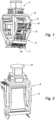
- a drilling device 1 comprising a drilling head 2 remarkable in that the drilling head 2 comprises a support block 3 of a plurality of cassettes 4.
- the cassettes 4 are mounted on the support block 3 in a removable manner.
- a cassette 4 is shown, in the phase of disassembly from or assembly on the support block 3, on which a counterweight 5 is visible intended for dynamic inertia balancing.
- a counterweight 5 equips each cassette 4 of the drilling device 1.
- Each cassette 4 is equipped with a brushless motor 6, two probes 7, and two drills 8 (see also FIG. 7 ).
- the two feelers 7 are located on either side of the two drills 8 so that the feelers 7 and the drills 8 are located substantially on the same axis.
- the support block 3 comprises a fixing interface 9 intended to allow the mounting of the drilling head 2 on the arm of a manipulator robot (not shown).
- the support block 3 also includes a module 10 for controlling the brushless motors 6.
- a cassette 4 which equips the drilling device 1.
- the brushless motor 6 is shown there connected to a first flat belt 11 itself cooperating with a ball screw 12. Thus the brushless motor 6 actuates the ball screw 12 via the first flat belt 11.
- the 12 ball screw acts as a mechanical actuator, it acts like a cylinder.
- the ball screw 12 is fixed to a fixed frame 13 of the cassette 4 which is substantially U-shaped in such a way that the head of the ball screw 12 in contact with the first flat belt 11 is substantially flush with the outer skin of the base of the fixed U-shaped frame 13.
- the counterweight 5 as well as a second flat belt 14 as well as the two feelers 7 and the two drills 8 are also shown.
- the fixed frame 13 has a substantially U shape, with a base 15 and two branches 16 and 17.
- the brushless motor 6 and the counterweight 5 are each connected to one end of the base 15.
- the base 15 and the branch 16 respectively comprise a shoe 18a and two shoes 18b, 18c for guiding the counterweight 5 in translation.
- the guidance thus obtained allows the counterweight 5 to translate substantially parallel to the branches 16 and 17.
- the branch 16 also includes the second flat belt 14 on which the counterweight 5 is attached.
- Each of the branches 16 and 17 comprises two translation guide pads 19a and 19b.
- the pads 19a, 19b of the branch 17 are symmetrical. to the pads 19a, 19b of the branch 16 relative to the main axis ⁇ of the fixed armature 13.
- a tapped hole 20 is made at the end of each of the branches 16 and 17 in such a way that a screw can penetrate into each of the holes 20 along the main axis of each of the branches 16 and 17.
- the ball screw passes through the base 15 of the fixed frame 13 and its main axis is substantially coincident with that ⁇ of the fixed frame 13.
- the thread of the ball screw extends over a length of approximately 35 mm.
- the second flat belt 14 is arranged along the branch 16 and extends between two pulleys 21a and 21b, the pulleys 21a and 21b being arranged in such a way that the shortest distance separating them is of a value greater than or equal to 35 mm.
- the belts referenced 11 and 14 are preferably flat but can also be toothed belts, trapezoidal belts, or any other type of belt. Similarly, the belts 11 and 14 can be chains.
- Flat belts have the advantage of being very quiet, being usable at high speeds, absorbing torsional vibrations and having very good performance, comparable to that of gears.
- the head of the ball screw 12 flush with the outer skin of the base 15 of the fixed frame 13 acts as a pulley for the first flat belt 11.
- the balls of the ball screw 12 interposed between the screw and its housing make it possible to significantly reduce or even eliminate the friction which occurs during the movement of the ball screw 12.
- ball screws have the advantage of high efficiency, allowing very precise adjustments with high travel speeds, and low heating.
- the counterweight 5 comprises an inertia mass 22 and a metal tab 23.
- the metal tab 23 comprises two rails 24a and 24b arranged between them and shaped so that the rail 24a cooperates with the shoe 18a ( Fig. 4 ) and that the rail 24b cooperates with the pads 18b and 18c.
- the counterweight 5 also comprises a connecting flange 25 for connecting the counterweight 5 and the second flat belt 14. The connecting flange “bites” the second flat belt 14 on a strand of it between the two pulleys.
- a drill support 26 comprising the feelers 7 each mounted on a spring 27, the drills 8, an electric sensor 28, side rails 29, a connecting flange 30, and a housing 31 for the ball screw 12 ( Fig. 4 ).
- the feelers 7 When pressure is exerted on the end of the feelers 7 intended for feeling, the feelers 7 retract towards the inside of the drill holder 26 under the effect of this pressure.
- the springs 27 are mounted on the feelers 7 in such a way that when the pressure is released, the feelers return to their initial position.
- the electric sensor 28 is installed in the drill holder 26 in such a way that it can detect the entry into its detection field of the distal end at the probing end of one of the probes 7.
- the electric sensor 28 therefore makes it possible to know automatically when this probe 7 has come into contact with the surface of the part to be drilled.
- the side rails 29 are intended to cooperate with the translation guide pads 19a and 19b.
- the connecting flange 30 is intended to connect the drill holder 26 and the second flat belt 14 in such a way that the connecting flange 30 “bites” the second flat belt 14 on the belt strand which is not “bitten” by the connecting flange 25 of the counterweight 5 ( Fig. 4 And 5 ).
- Housing 31 is the housing of the ball screw 12 in the drill holder 26.
- the electrical hysteresis of the detection must be as short as possible, therefore a specific sensor, for example of the laser sensor type, can be used instead of the electrical sensor 28, on the other hand the distal end at the probing end of the probe 7 to be detected can also be made of soft iron or covered with a layer of soft iron.
- the senor is mounted on an adjustable plate with a fine-pitch screw and held in position after adjustment.
- a possible failure of this sensor can be compensated for by an automation system ensuring redundancy in the vicinity, i.e. in the event of non-detection of the distal end at the probing end of the probe 7, it will be considered that the sensor is faulty, and the automation will then command that the drills of the faulty cassette advance at the same speed as the drills of the cassettes immediately adjacent via the sensors of the cassettes immediately adjacent.
- This advantage avoids each of the cassettes being equipped with two sensors, one of which is taken into account in the event of failure of the other.
- Such a probing device makes it possible to automatically control the drilling depth of the drills of each cassette.
- control has the advantage of allowing, if necessary, drilling of the acoustic skins after assembly of the acoustic skins with honeycomb structures without significant damage to the honeycomb structures and without the drilling drills passing right through the final acoustic parts, if necessary.
- cassette 4 In reference to the figure 7 , the general operation of cassette 4 is described.
- the Brushless motor When the Brushless motor is actuated, it drives the first flat belt 11 in its travel.
- the first flat belt 11 being connected to the ball screw head 12 acting as a pulley, the ball screw 12 is therefore driven in rotation.
- the ball screw When it rotates, the ball screw does not have any translational movement relative to the fixed frame 13, the ball screw 12 is in pivot connection with the fixed frame 13.
- the ball screw 12 drives the drill support 26 thanks to the housing 31 comprising a ball nut.
- the drill support 26 then translates along the branches 16 and 17 thanks to its two rails 29 and to the pads 19a and 19b for guiding the fixed frame 13 in translation.
- the connecting flange 30 of the drill support 26 also moves along an axis parallel to the axes of the branches 16 and 17, driving in its movement the second flat belt 14 placed on the two pulleys 21a and 21b.
- the second flat belt 14 then drives in its movement the connecting flange 25 of the counterweight 5 which, “biting” the strand of the second flat belt 14 left free by the connecting flange 30, also translates thanks to the rails 24a and 24b and to the pads 18a, 18b, 18c for guiding in translation along an axis parallel to the axes of the branches 16 and 17; but the connecting flange 25 moves in the opposite direction to the direction of movement of the connecting flange 30 of the drill support 26.
- the drill support 26 and the counterweight 5 both translate in a synchronized manner, along parallel axes, and in opposite directions. It is in this way that the counterweight 5 makes it possible to obtain the dynamic inertia balancing.
- the cassettes 4 are fixed to the support block 3 by means of the tapped holes 20 and suitable screws (not shown).
- the cassettes 4 are positioned relative to the support block 3 in such a way that the tapped holes 20 are all opposite a smooth hole 32 whose diameter is greater than the nominal diameter of the screws intended to be screwed into the tapped holes 20, but less than the head of said screws.
- the assembly and disassembly of a cassette 4 fixed to the support block 3 is therefore very easy and does not require the intervention of a maintenance team when a cassette 4 is defective and must be replaced.
- the assembly comprising the support block 3 and the cassettes 4 forms the drilling head 2 ( Fig. 1 ).
- the drilling head 2 is moved by the arm of a manipulator robot or a 5-axis machine (not shown) programmed to move the drilling head 2 over the successive zones of a part to be drilled (not shown).
- the drill holder 26 of each cassette 4 moves so that all the drills 8 of all the cassettes 4 are at the same distance from the area of the part opposite them. This operation is made possible by the feelers 7 of the cassettes 4 which, in cooperation with the electric sensor 28, allow the surface of the part to be drilled to be detected and the height of the drill holder 26 to be adjusted accordingly.
- the drilling operation begins when all the probes 7 of the cassettes 4 are in contact with the surface of the part to be drilled and when the heights of the drill supports 26 relative to the surface of the part to be drilled are all identical.
- the drilling device 1 as described above can be enhanced with a program and associated apparatus making it possible to record the different configurations of the drill supports 26 relative to each other for each zone of the part to be drilled above which the drilling head 2 is positioned.
- the drilling head 2 configures itself more quickly when moving from one zone to be drilled to another if it has to drill a part that it has already drilled once, since it can adjust the positioning of the drill supports 26 of the cassettes 4 relative to each other during its movement from one zone to be drilled to another.
Landscapes
- Engineering & Computer Science (AREA)
- Mechanical Engineering (AREA)
- Physics & Mathematics (AREA)
- Acoustics & Sound (AREA)
- Multimedia (AREA)
- Perforating, Stamping-Out Or Severing By Means Other Than Cutting (AREA)
- Drilling And Boring (AREA)
- Processing Of Stones Or Stones Resemblance Materials (AREA)
Claims (14)
- Vorrichtung (1) zum Bohren einer akustischen Komponente, die einen Bohrkopf (2) umfasst, wobei der Bohrkopf (2) einen Trägerblock (3) umfasst, der mindestens zwei autonome Bohrkassetten (4) umfasst, die jeweils mindestens einen Bohrer (8), eine in Bezug auf den Trägerblock (3) feste Bewehrung (13) und einen Bohrerträger (26) umfassen, der entlang der Hauptachse (Δ) der Kassette zwischen einer eingefahrenen Position und einer ausgefahrenen Position beweglich ist, dadurch gekennzeichnet, dass jeder Bohrerträger (26) mit mindestens einer Abtastvorrichtung (7) für die Haut der zu bohrenden akustischen Komponente ausgestattet ist, die es ermöglicht, die Bohrtiefe der Bohrer jeder Kassette automatisch zu steuern, wobei die Abtastvorrichtung mindestens einen Taster und mindestens einen Sensor umfasst, der es ermöglicht, mit Hilfe der Taster die Position der Bohrer in Bezug auf die Haut der zu bohrenden akustischen Komponente zu erkennen.
- Vorrichtung (1) nach Anspruch 1, dadurch gekennzeichnet, dass jede Kassette (4) ein Mittel (12) zum Verschiebebewegen ihres Bohrerträgers (26) mittels eines Mechanismus, der an ihrer festen Bewehrung (13) und am Bohrerträger (26) angebracht ist, umfasst.
- Vorrichtung (1) nach einem der Ansprüche 2, dadurch gekennzeichnet, dass das Verschiebebewegungsmittel (12) eine Kugelumlaufspindel (12) ist, wobei die Kugelumlaufspindel (12) an der festen Bewehrung (13) der Kassette (4) angebracht ist.
- Vorrichtung (1) nach einem der Ansprüche 2 oder 3, dadurch gekennzeichnet, dass das Verschiebebewegungsmittel (12) es ermöglicht, den Bohrerträger (26) auf eine Zwischenposition zwischen seiner eingefahrenen Position und seiner ausgefahrenen Position einzustellen.
- Vorrichtung (1) nach einem der vorstehenden Ansprüche, dadurch gekennzeichnet, dass jede Kassette (4) abnehmbar am Trägerblock (3) befestigt ist.
- Vorrichtung (1) nach Anspruch 5, dadurch gekennzeichnet, dass die Kassetten (4) mittels Schrauben oder durch Einrasten am Trägerblock (3) befestigt sind.
- Vorrichtung (1) nach einem der vorstehenden Ansprüche, dadurch gekennzeichnet, dass jede Kassette (4) zwei Bohrer (8) umfasst.
- Vorrichtung (1) nach einem der vorstehenden Ansprüche, dadurch gekennzeichnet, dass die Kassetten (4) in Reihe im Wesentlichen zusammenhängend am Trägerblock (3) angeordnet sind.
- Vorrichtung (1) nach Anspruch 8, dadurch gekennzeichnet, dass sie elf in Reihe angeordnete Kassetten (4) umfasst, die jeweils zwei Bohrer (8) umfassen, die beiderseits der Achse der so gebildeten Reihe angeordnet sind.
- Vorrichtung (1) nach einem der vorstehenden Ansprüche, dadurch gekennzeichnet, dass jede Kassette (4) ein Mittel (5) zum dynamischen Ausgleichen der Trägheit umfasst.
- Vorrichtung (1) nach einem der vorstehenden Ansprüche, dadurch gekennzeichnet, dass jede Kassette (4) mit einem bürstenlosen Motor (6) ausgestattet ist.
- Vorrichtung (1) nach Anspruch 1, dadurch gekennzeichnet, dass die Abtastvorrichtung (7) es ermöglicht, die Position des Bohrerträgers (26) in Bezug auf die Haut der zu bohrenden Komponente einzustellen.
- Akustisches Bohrverfahren, dadurch gekennzeichnet, dass es eine Vorrichtung (1) zum Bohren von akustischen Komponenten nach einem der Ansprüche 1 bis 12 zum Einsatz bringt.
- Verfahren zur Herstellung einer akustischen Komponente, die eine akustische Haut und eine Wabenstruktur umfasst, wobei das Verfahren die folgenden Schritte in dieser Reihenfolge umfasst:- Drapieren der akustischen Haut einer Kohlenstoffbahn Gewebeform,- Drapieren einer doppelseitigen Polymerbahn, um das spätere Kleben der akustischen Haut auf eine Wabenstruktur zu ermöglichen;- Hinzugeben der Wabenstruktur auf die akustische Haut;- einmaliges Brennen, um die Kohlenstoff- und die zweiseitige Bahn der akustischen Haut zu polymerisieren und das Verbinden der akustischen Haut mit der Wabenstruktur abzuschließen;- Bohren der akustischen Haut mit einer akustischen Bohrvorrichtung nach einem der Ansprüche 1 bis 12, was es so ermöglicht, den Durchmesser der so gebohrten akustischen Löcher und damit die akustische Leistung der fertigen akustischen Komponente zu steuern.
Applications Claiming Priority (2)
| Application Number | Priority Date | Filing Date | Title |
|---|---|---|---|
| FR1351028A FR3001645B1 (fr) | 2013-02-06 | 2013-02-06 | Tete de percage acoustique |
| PCT/FR2014/050220 WO2014122400A1 (fr) | 2013-02-06 | 2014-02-05 | Dispositif de perçage d'une pièce acoustique, cassette, procédé de perçage acoustique et procédé de fabrication d'une pièce acoustique |
Publications (2)
| Publication Number | Publication Date |
|---|---|
| EP2953751A1 EP2953751A1 (de) | 2015-12-16 |
| EP2953751B1 true EP2953751B1 (de) | 2024-10-30 |
Family
ID=48224997
Family Applications (1)
| Application Number | Title | Priority Date | Filing Date |
|---|---|---|---|
| EP14706894.4A Active EP2953751B1 (de) | 2013-02-06 | 2014-02-05 | Vorrichtung zum bohren einer akustischen komponente, akustisches bohrverfahren und verfahren zur herstellung einer akustischen komponente |
Country Status (8)
| Country | Link |
|---|---|
| US (1) | US10189095B2 (de) |
| EP (1) | EP2953751B1 (de) |
| CN (1) | CN104968457A (de) |
| BR (1) | BR112015016755A2 (de) |
| CA (1) | CA2897692C (de) |
| FR (1) | FR3001645B1 (de) |
| RU (1) | RU2015134073A (de) |
| WO (1) | WO2014122400A1 (de) |
Families Citing this family (6)
| Publication number | Priority date | Publication date | Assignee | Title |
|---|---|---|---|---|
| US9616503B2 (en) * | 2014-09-10 | 2017-04-11 | The Boeing Company | Apparatuses and methods for processing a confined area of a workpiece |
| CN107107207B (zh) | 2014-11-18 | 2018-09-14 | 艾沛克斯品牌公司 | 对多个工具进行机器定位的系统和方法 |
| US10702928B2 (en) * | 2017-02-13 | 2020-07-07 | Spirit Aerosystems, Inc. | Method and apparatus for acoustic perforation of core sandwich panels |
| CN115070079B (zh) * | 2022-07-18 | 2024-05-28 | 南通佳景健康科技股份有限公司 | 一种基于激光定位的水疗按摩池镂孔加工机器人 |
| FR3159106A1 (fr) | 2024-02-12 | 2025-08-15 | Le Creneau Industriel | Procédé de perçage d’une pièce à usiner, notamment à surface(s) courbée(s), avec ajustement de la position d’outils d’usinage d’un effecteur de robot par rapport à la pièce mesure individuelle sans contact par laser de chaque outil. |
| CN118650469B (zh) * | 2024-07-10 | 2025-05-27 | 浙江大学 | 用于航空发动机短舱声衬制孔的排气道声衬定位工装 |
Family Cites Families (40)
| Publication number | Priority date | Publication date | Assignee | Title |
|---|---|---|---|---|
| US1962566A (en) * | 1930-06-25 | 1934-06-12 | Ralph M Lovejoy | Automatic drilling machine and machine for other purposes |
| US2506202A (en) * | 1948-08-13 | 1950-05-02 | Sr Harold E Folkerth | Multiple close centered gear head |
| US7065856B1 (en) * | 1954-07-28 | 2006-06-27 | Lemelson Jerome H | Machine tool method |
| FR2050688A5 (de) * | 1969-06-20 | 1971-04-02 | Sirugue Et Cie | |
| GB1343674A (en) * | 1971-05-28 | 1974-01-16 | Mollart Eng Co Ltd | Machine tool having interchangeable tool carrying units |
| JPS5827048B2 (ja) * | 1974-03-03 | 1983-06-07 | ミヤガワコウギヨウ カブシキガイシヤ | H ガタコウヨウタジクセンコウキ |
| US3973859A (en) * | 1975-02-24 | 1976-08-10 | Grumman Aerospace Corporation | Automated drilling system |
| US4090803A (en) * | 1977-03-01 | 1978-05-23 | Haley Ernest K | Drilling head system for I-beams |
| US4162134A (en) * | 1978-01-12 | 1979-07-24 | Miyakawa Industry Company Limited | Apparatus for adjusting vertical position of drills in multiple spindle drilling machine |
| US4493595A (en) * | 1978-09-25 | 1985-01-15 | Colt Industries Operating Corp | Compact multiple spindle boring head with quick change tool supports |
| US4198181A (en) * | 1978-09-25 | 1980-04-15 | Smelser James M | Apparatus for drilling holes in "H" beams |
| US4397074A (en) * | 1981-02-04 | 1983-08-09 | Ashcombe Products Company | Method of forming a gang cutting tool assembly and tool formed thereby |
| US4419803A (en) * | 1981-02-04 | 1983-12-13 | Ashcombe Products Company | Method of forming a tool assembly |
| US4441245A (en) * | 1981-02-04 | 1984-04-10 | Ashcombe Products Company | Gang cutting tool assembly |
| DE3324809A1 (de) * | 1983-07-09 | 1985-01-17 | Dornier System Gmbh, 7990 Friedrichshafen | Verfahren zum vorbereiten einer holzimpraegnierung |
| US4759513A (en) * | 1986-09-26 | 1988-07-26 | Quiet Nacelle Corporation | Noise reduction nacelle |
| US4674925A (en) * | 1986-10-03 | 1987-06-23 | Ashcombe Products Company | Gang drill and method for clearing patterns of holes in tubular members |
| US4813822A (en) * | 1988-01-05 | 1989-03-21 | Dresser Industries, Inc. | Power drill system with adjustable depth sensing means |
| US4984352A (en) * | 1988-03-07 | 1991-01-15 | Micromation Systems, Inc. | Thin panel drilling method and apparatus |
| US4847979A (en) * | 1988-03-07 | 1989-07-18 | Micromation Systems, Inc. | "Tool changer having a retaining means actuatable during loading of a bit along the central axis of a pocket" |
| US4932117A (en) * | 1988-03-07 | 1990-06-12 | Micromation Systems, Inc. | Thin panel drilling method and apparatus |
| US5147160A (en) * | 1988-03-07 | 1992-09-15 | Micromation Systems, Inc. | Thin panel drilling method and apparatus |
| IT1240531B (it) * | 1990-08-07 | 1993-12-17 | Pluritec Italia | Metodo e dispositivo di controllo della profondita' di lavorazione per una macchina utensile a controllo numerico |
| RU2064691C1 (ru) * | 1992-05-05 | 1996-07-27 | Товарищество с ограниченной ответственностью "Аэрос" | Звукопоглощающая конструкция |
| FR2703280B1 (fr) * | 1993-04-02 | 1996-07-12 | Recoules Fils Ets | Procédé et dispositif de montage d'outillages. |
| US5920973A (en) * | 1997-03-09 | 1999-07-13 | Electro Scientific Industries, Inc. | Hole forming system with multiple spindles per station |
| US6438446B1 (en) * | 1998-07-13 | 2002-08-20 | Fredrick J. Trachier | Material directory-spindle speed and feed rate calculator |
| KR100671875B1 (ko) * | 1999-05-21 | 2007-01-19 | 도요다고키 가부시키가이샤 | 다축 가공 장치 |
| IT1310503B1 (it) * | 1999-09-30 | 2002-02-18 | Hsd Srl | Testa di foratura portamandrini per macchine utensili atte a lavorareper asportazione di truciolo dei pannelli. |
| US6527686B1 (en) * | 2000-02-02 | 2003-03-04 | International Business Machines Corporation | Variable pitch spindle line drilling machine |
| ITMI20011509A1 (it) * | 2001-07-13 | 2003-01-13 | Luigi Reguzzi | Gruppo per l'azionamento di una pluralita' di mandrini |
| CA2400885C (en) * | 2001-08-31 | 2011-01-25 | Valley Gear & Machine, Inc. | Method and apparatus for forming openings in polymeric tubing |
| CN2502825Y (zh) * | 2001-09-10 | 2002-07-31 | 河北新河新钻有限公司 | 一种潜水式多头钻成槽钻具 |
| US6569071B1 (en) * | 2002-06-17 | 2003-05-27 | The Regents Of The University Of Michigan | Reconfigurable multi-spindle apparatus |
| DE10259285A1 (de) * | 2002-12-18 | 2004-07-08 | Weeke Bohrsysteme Gmbh | Modulartiges Spindelaggregat |
| DE102004009080B4 (de) * | 2004-02-25 | 2006-06-22 | Wilhelm Karmann Gmbh | Akustischer Absorber |
| US7313850B2 (en) * | 2005-05-16 | 2008-01-01 | Lee Norris Miller | Compact, economical, multi-axis, multi-tasking, small part machine tool |
| DE102007038462A1 (de) * | 2007-08-14 | 2009-02-19 | Wittenstein Ag | Modulartiges Spindelaggregat |
| CN201086146Y (zh) * | 2007-09-28 | 2008-07-16 | 余敏守 | 异扭力多轴钻孔机 |
| WO2013161330A1 (ja) * | 2012-04-26 | 2013-10-31 | 本田技研工業株式会社 | 工作機械 |
-
2013
- 2013-02-06 FR FR1351028A patent/FR3001645B1/fr active Active
-
2014
- 2014-02-05 BR BR112015016755A patent/BR112015016755A2/pt not_active IP Right Cessation
- 2014-02-05 CN CN201480007690.1A patent/CN104968457A/zh active Pending
- 2014-02-05 EP EP14706894.4A patent/EP2953751B1/de active Active
- 2014-02-05 CA CA2897692A patent/CA2897692C/fr active Active
- 2014-02-05 WO PCT/FR2014/050220 patent/WO2014122400A1/fr not_active Ceased
- 2014-02-05 RU RU2015134073A patent/RU2015134073A/ru not_active Application Discontinuation
-
2015
- 2015-08-04 US US14/817,244 patent/US10189095B2/en active Active
Also Published As
| Publication number | Publication date |
|---|---|
| CA2897692C (fr) | 2020-08-18 |
| US10189095B2 (en) | 2019-01-29 |
| CN104968457A (zh) | 2015-10-07 |
| RU2015134073A (ru) | 2017-03-14 |
| FR3001645A1 (fr) | 2014-08-08 |
| US20150336180A1 (en) | 2015-11-26 |
| CA2897692A1 (fr) | 2014-08-14 |
| FR3001645B1 (fr) | 2015-05-15 |
| BR112015016755A2 (pt) | 2017-07-11 |
| WO2014122400A1 (fr) | 2014-08-14 |
| EP2953751A1 (de) | 2015-12-16 |
Similar Documents
| Publication | Publication Date | Title |
|---|---|---|
| CA2897692C (fr) | Dispositif de percage d'une piece acoustique, cassette, procede de percage acoustique et procede de fabrication d'une piece acoustique | |
| CA2760063C (fr) | Tete de percage a vibrations axiales | |
| CA2857719C (fr) | Procede d'usinage | |
| KR20070114299A (ko) | 제거 장치용 회전식 제거 헤드 | |
| JP4931920B2 (ja) | ケーブル剥離装置および剥離方法 | |
| CA2965394C (fr) | Dispositif d'usinage vibratoire ameliore | |
| EP0216695B1 (de) | Verfahren und Maschine zur Herstellung von Rotationshohlkörpern aus in drei verschiedenen Richtungen verlaufenden Gespinstfasern | |
| WO2015140334A1 (fr) | Machine-outil notamment de perçage | |
| EP3983170B1 (de) | Spindel mit piezoelektrischen aktuatoren | |
| WO2018087488A1 (fr) | Dispositif porte-outil pour appareil de fabrication additive selective | |
| EP2767357B1 (de) | Maschinelles Fertigungsverfahren eines Lochs, das in ein Werkstück mündet, und Fertigungsvorrichtung für die Umsetzung dieses Verfahrens | |
| FR3121622A1 (fr) | Tete de prehension et de poinçonnage d’une piece permettant son entrainement en rotation pour son usinage | |
| FR2611155A1 (fr) | Dispositif de soudage aux ultrasons notamment pour des composants semi-conducteurs avec un guidage axial et radial de la tete de soudage rotative | |
| FR3070886A1 (fr) | Appareil et procede pour minimiser l'allongement de trous perces | |
| FR2464793A1 (fr) | Mecanisme d'ejection d'outil et machine equipes d'un tel mecanisme | |
| FR2629448A1 (fr) | Appareillage pour decouper une piece en un materiau du type verre ou ceramique le long d'une ligne incisee | |
| FR2921577A1 (fr) | Procede de fabrication d'une machine outil a mouvement orbital, machine-outil obtenue selon le procede et procede d'usinage | |
| FR2906741A1 (fr) | Centre d'usinage de profiles de grande longueur | |
| FR2966764A1 (fr) | Machine d'usinage pour des grumes | |
| ITUD20150055A1 (it) | Macchina pelatrice per prodotti oblunghi | |
| EP3110585B1 (de) | Drehautomaten, steuereinheit für drehautomaten und nachrüstungsverfahren für eine derartige einheit | |
| EP2361173B1 (de) | Vorrichtung zur Herstellung von länglichen rotationssymmetrischen Teilen | |
| CH703795B1 (fr) | Machine de décolletage. | |
| FR2938061A1 (fr) | Procede et dispositif de mesure des caracteristiques d'un amortisseur de torsion. | |
| WO2004004975A1 (fr) | Procede d'ebavurage a haute pression |
Legal Events
| Date | Code | Title | Description |
|---|---|---|---|
| PUAI | Public reference made under article 153(3) epc to a published international application that has entered the european phase |
Free format text: ORIGINAL CODE: 0009012 |
|
| 17P | Request for examination filed |
Effective date: 20150806 |
|
| AK | Designated contracting states |
Kind code of ref document: A1 Designated state(s): AL AT BE BG CH CY CZ DE DK EE ES FI FR GB GR HR HU IE IS IT LI LT LU LV MC MK MT NL NO PL PT RO RS SE SI SK SM TR |
|
| AX | Request for extension of the european patent |
Extension state: BA ME |
|
| DAX | Request for extension of the european patent (deleted) | ||
| RAP1 | Party data changed (applicant data changed or rights of an application transferred) |
Owner name: SAFRAN NACELLES |
|
| STAA | Information on the status of an ep patent application or granted ep patent |
Free format text: STATUS: EXAMINATION IS IN PROGRESS |
|
| 17Q | First examination report despatched |
Effective date: 20210304 |
|
| GRAP | Despatch of communication of intention to grant a patent |
Free format text: ORIGINAL CODE: EPIDOSNIGR1 |
|
| STAA | Information on the status of an ep patent application or granted ep patent |
Free format text: STATUS: GRANT OF PATENT IS INTENDED |
|
| RIC1 | Information provided on ipc code assigned before grant |
Ipc: G10K 11/172 20060101ALI20240228BHEP Ipc: B23B 49/00 20060101ALI20240228BHEP Ipc: B23B 39/16 20060101AFI20240228BHEP |
|
| INTG | Intention to grant announced |
Effective date: 20240403 |
|
| GRAJ | Information related to disapproval of communication of intention to grant by the applicant or resumption of examination proceedings by the epo deleted |
Free format text: ORIGINAL CODE: EPIDOSDIGR1 |
|
| STAA | Information on the status of an ep patent application or granted ep patent |
Free format text: STATUS: EXAMINATION IS IN PROGRESS |
|
| GRAP | Despatch of communication of intention to grant a patent |
Free format text: ORIGINAL CODE: EPIDOSNIGR1 |
|
| STAA | Information on the status of an ep patent application or granted ep patent |
Free format text: STATUS: GRANT OF PATENT IS INTENDED |
|
| INTC | Intention to grant announced (deleted) | ||
| INTG | Intention to grant announced |
Effective date: 20240606 |
|
| GRAS | Grant fee paid |
Free format text: ORIGINAL CODE: EPIDOSNIGR3 |
|
| GRAA | (expected) grant |
Free format text: ORIGINAL CODE: 0009210 |
|
| STAA | Information on the status of an ep patent application or granted ep patent |
Free format text: STATUS: THE PATENT HAS BEEN GRANTED |
|
| AK | Designated contracting states |
Kind code of ref document: B1 Designated state(s): AL AT BE BG CH CY CZ DE DK EE ES FI FR GB GR HR HU IE IS IT LI LT LU LV MC MK MT NL NO PL PT RO RS SE SI SK SM TR |
|
| REG | Reference to a national code |
Ref country code: GB Ref legal event code: FG4D Free format text: NOT ENGLISH |
|
| REG | Reference to a national code |
Ref country code: CH Ref legal event code: EP |
|
| REG | Reference to a national code |
Ref country code: IE Ref legal event code: FG4D Free format text: LANGUAGE OF EP DOCUMENT: FRENCH |
|
| REG | Reference to a national code |
Ref country code: DE Ref legal event code: R096 Ref document number: 602014091079 Country of ref document: DE |
|
| REG | Reference to a national code |
Ref country code: LT Ref legal event code: MG9D |
|
| REG | Reference to a national code |
Ref country code: NL Ref legal event code: MP Effective date: 20241030 |
|
| PG25 | Lapsed in a contracting state [announced via postgrant information from national office to epo] |
Ref country code: IS Free format text: LAPSE BECAUSE OF FAILURE TO SUBMIT A TRANSLATION OF THE DESCRIPTION OR TO PAY THE FEE WITHIN THE PRESCRIBED TIME-LIMIT Effective date: 20250228 Ref country code: PT Free format text: LAPSE BECAUSE OF FAILURE TO SUBMIT A TRANSLATION OF THE DESCRIPTION OR TO PAY THE FEE WITHIN THE PRESCRIBED TIME-LIMIT Effective date: 20250228 Ref country code: HR Free format text: LAPSE BECAUSE OF FAILURE TO SUBMIT A TRANSLATION OF THE DESCRIPTION OR TO PAY THE FEE WITHIN THE PRESCRIBED TIME-LIMIT Effective date: 20241030 |
|
| PG25 | Lapsed in a contracting state [announced via postgrant information from national office to epo] |
Ref country code: FI Free format text: LAPSE BECAUSE OF FAILURE TO SUBMIT A TRANSLATION OF THE DESCRIPTION OR TO PAY THE FEE WITHIN THE PRESCRIBED TIME-LIMIT Effective date: 20241030 Ref country code: NL Free format text: LAPSE BECAUSE OF FAILURE TO SUBMIT A TRANSLATION OF THE DESCRIPTION OR TO PAY THE FEE WITHIN THE PRESCRIBED TIME-LIMIT Effective date: 20241030 |
|
| REG | Reference to a national code |
Ref country code: AT Ref legal event code: MK05 Ref document number: 1736430 Country of ref document: AT Kind code of ref document: T Effective date: 20241030 |
|
| PG25 | Lapsed in a contracting state [announced via postgrant information from national office to epo] |
Ref country code: BG Free format text: LAPSE BECAUSE OF FAILURE TO SUBMIT A TRANSLATION OF THE DESCRIPTION OR TO PAY THE FEE WITHIN THE PRESCRIBED TIME-LIMIT Effective date: 20241030 |
|
| PG25 | Lapsed in a contracting state [announced via postgrant information from national office to epo] |
Ref country code: ES Free format text: LAPSE BECAUSE OF FAILURE TO SUBMIT A TRANSLATION OF THE DESCRIPTION OR TO PAY THE FEE WITHIN THE PRESCRIBED TIME-LIMIT Effective date: 20241030 |
|
| PG25 | Lapsed in a contracting state [announced via postgrant information from national office to epo] |
Ref country code: NO Free format text: LAPSE BECAUSE OF FAILURE TO SUBMIT A TRANSLATION OF THE DESCRIPTION OR TO PAY THE FEE WITHIN THE PRESCRIBED TIME-LIMIT Effective date: 20250130 |
|
| PG25 | Lapsed in a contracting state [announced via postgrant information from national office to epo] |
Ref country code: LV Free format text: LAPSE BECAUSE OF FAILURE TO SUBMIT A TRANSLATION OF THE DESCRIPTION OR TO PAY THE FEE WITHIN THE PRESCRIBED TIME-LIMIT Effective date: 20241030 Ref country code: AT Free format text: LAPSE BECAUSE OF FAILURE TO SUBMIT A TRANSLATION OF THE DESCRIPTION OR TO PAY THE FEE WITHIN THE PRESCRIBED TIME-LIMIT Effective date: 20241030 Ref country code: GR Free format text: LAPSE BECAUSE OF FAILURE TO SUBMIT A TRANSLATION OF THE DESCRIPTION OR TO PAY THE FEE WITHIN THE PRESCRIBED TIME-LIMIT Effective date: 20250131 |
|
| PG25 | Lapsed in a contracting state [announced via postgrant information from national office to epo] |
Ref country code: PL Free format text: LAPSE BECAUSE OF FAILURE TO SUBMIT A TRANSLATION OF THE DESCRIPTION OR TO PAY THE FEE WITHIN THE PRESCRIBED TIME-LIMIT Effective date: 20241030 |
|
| PG25 | Lapsed in a contracting state [announced via postgrant information from national office to epo] |
Ref country code: RS Free format text: LAPSE BECAUSE OF FAILURE TO SUBMIT A TRANSLATION OF THE DESCRIPTION OR TO PAY THE FEE WITHIN THE PRESCRIBED TIME-LIMIT Effective date: 20250130 |
|
| PG25 | Lapsed in a contracting state [announced via postgrant information from national office to epo] |
Ref country code: SM Free format text: LAPSE BECAUSE OF FAILURE TO SUBMIT A TRANSLATION OF THE DESCRIPTION OR TO PAY THE FEE WITHIN THE PRESCRIBED TIME-LIMIT Effective date: 20241030 |
|
| PG25 | Lapsed in a contracting state [announced via postgrant information from national office to epo] |
Ref country code: DK Free format text: LAPSE BECAUSE OF FAILURE TO SUBMIT A TRANSLATION OF THE DESCRIPTION OR TO PAY THE FEE WITHIN THE PRESCRIBED TIME-LIMIT Effective date: 20241030 |
|
| PG25 | Lapsed in a contracting state [announced via postgrant information from national office to epo] |
Ref country code: EE Free format text: LAPSE BECAUSE OF FAILURE TO SUBMIT A TRANSLATION OF THE DESCRIPTION OR TO PAY THE FEE WITHIN THE PRESCRIBED TIME-LIMIT Effective date: 20241030 |
|
| PG25 | Lapsed in a contracting state [announced via postgrant information from national office to epo] |
Ref country code: RO Free format text: LAPSE BECAUSE OF FAILURE TO SUBMIT A TRANSLATION OF THE DESCRIPTION OR TO PAY THE FEE WITHIN THE PRESCRIBED TIME-LIMIT Effective date: 20241030 |
|
| PG25 | Lapsed in a contracting state [announced via postgrant information from national office to epo] |
Ref country code: SK Free format text: LAPSE BECAUSE OF FAILURE TO SUBMIT A TRANSLATION OF THE DESCRIPTION OR TO PAY THE FEE WITHIN THE PRESCRIBED TIME-LIMIT Effective date: 20241030 |
|
| PG25 | Lapsed in a contracting state [announced via postgrant information from national office to epo] |
Ref country code: CZ Free format text: LAPSE BECAUSE OF FAILURE TO SUBMIT A TRANSLATION OF THE DESCRIPTION OR TO PAY THE FEE WITHIN THE PRESCRIBED TIME-LIMIT Effective date: 20241030 |
|
| PG25 | Lapsed in a contracting state [announced via postgrant information from national office to epo] |
Ref country code: IT Free format text: LAPSE BECAUSE OF FAILURE TO SUBMIT A TRANSLATION OF THE DESCRIPTION OR TO PAY THE FEE WITHIN THE PRESCRIBED TIME-LIMIT Effective date: 20241030 |
|
| REG | Reference to a national code |
Ref country code: DE Ref legal event code: R097 Ref document number: 602014091079 Country of ref document: DE |
|
| PLBE | No opposition filed within time limit |
Free format text: ORIGINAL CODE: 0009261 |
|
| STAA | Information on the status of an ep patent application or granted ep patent |
Free format text: STATUS: NO OPPOSITION FILED WITHIN TIME LIMIT |
|
| PG25 | Lapsed in a contracting state [announced via postgrant information from national office to epo] |
Ref country code: SE Free format text: LAPSE BECAUSE OF FAILURE TO SUBMIT A TRANSLATION OF THE DESCRIPTION OR TO PAY THE FEE WITHIN THE PRESCRIBED TIME-LIMIT Effective date: 20241030 |
|
| PG25 | Lapsed in a contracting state [announced via postgrant information from national office to epo] |
Ref country code: MC Free format text: LAPSE BECAUSE OF FAILURE TO SUBMIT A TRANSLATION OF THE DESCRIPTION OR TO PAY THE FEE WITHIN THE PRESCRIBED TIME-LIMIT Effective date: 20241030 |
|
| REG | Reference to a national code |
Ref country code: CH Ref legal event code: PL |
|
| 26N | No opposition filed |
Effective date: 20250731 |
|
| PG25 | Lapsed in a contracting state [announced via postgrant information from national office to epo] |
Ref country code: LU Free format text: LAPSE BECAUSE OF NON-PAYMENT OF DUE FEES Effective date: 20250205 |
|
| PG25 | Lapsed in a contracting state [announced via postgrant information from national office to epo] |
Ref country code: CH Free format text: LAPSE BECAUSE OF NON-PAYMENT OF DUE FEES Effective date: 20250228 |
|
| REG | Reference to a national code |
Ref country code: BE Ref legal event code: MM Effective date: 20250228 |
|
| PG25 | Lapsed in a contracting state [announced via postgrant information from national office to epo] |
Ref country code: BE Free format text: LAPSE BECAUSE OF NON-PAYMENT OF DUE FEES Effective date: 20250228 |
|
| PG25 | Lapsed in a contracting state [announced via postgrant information from national office to epo] |
Ref country code: IE Free format text: LAPSE BECAUSE OF NON-PAYMENT OF DUE FEES Effective date: 20250205 |
|
| PGFP | Annual fee paid to national office [announced via postgrant information from national office to epo] |
Ref country code: GB Payment date: 20260219 Year of fee payment: 13 |
|
| PGFP | Annual fee paid to national office [announced via postgrant information from national office to epo] |
Ref country code: DE Payment date: 20260217 Year of fee payment: 13 |
|
| PGFP | Annual fee paid to national office [announced via postgrant information from national office to epo] |
Ref country code: FR Payment date: 20260213 Year of fee payment: 13 |