EP2953213B1 - Connector assembly and encoding element for same and method for encoding a connector assembly - Google Patents
Connector assembly and encoding element for same and method for encoding a connector assembly Download PDFInfo
- Publication number
- EP2953213B1 EP2953213B1 EP15170670.2A EP15170670A EP2953213B1 EP 2953213 B1 EP2953213 B1 EP 2953213B1 EP 15170670 A EP15170670 A EP 15170670A EP 2953213 B1 EP2953213 B1 EP 2953213B1
- Authority
- EP
- European Patent Office
- Prior art keywords
- plug
- type connector
- coding element
- latching
- coding
- Prior art date
- Legal status (The legal status is an assumption and is not a legal conclusion. Google has not performed a legal analysis and makes no representation as to the accuracy of the status listed.)
- Active
Links
Images


Classifications
-
- H—ELECTRICITY
- H01—ELECTRIC ELEMENTS
- H01R—ELECTRICALLY-CONDUCTIVE CONNECTIONS; STRUCTURAL ASSOCIATIONS OF A PLURALITY OF MUTUALLY-INSULATED ELECTRICAL CONNECTING ELEMENTS; COUPLING DEVICES; CURRENT COLLECTORS
- H01R13/00—Details of coupling devices of the kinds covered by groups H01R12/70 or H01R24/00 - H01R33/00
- H01R13/62—Means for facilitating engagement or disengagement of coupling parts or for holding them in engagement
- H01R13/639—Additional means for holding or locking coupling parts together, after engagement, e.g. separate keylock, retainer strap
-
- H—ELECTRICITY
- H01—ELECTRIC ELEMENTS
- H01R—ELECTRICALLY-CONDUCTIVE CONNECTIONS; STRUCTURAL ASSOCIATIONS OF A PLURALITY OF MUTUALLY-INSULATED ELECTRICAL CONNECTING ELEMENTS; COUPLING DEVICES; CURRENT COLLECTORS
- H01R13/00—Details of coupling devices of the kinds covered by groups H01R12/70 or H01R24/00 - H01R33/00
- H01R13/64—Means for preventing incorrect coupling
- H01R13/645—Means for preventing incorrect coupling by exchangeable elements on case or base
- H01R13/6456—Means for preventing incorrect coupling by exchangeable elements on case or base comprising keying elements at different positions along the periphery of the connector
Definitions
- the invention relates to a connector assembly having a connector and a mating connector, each having a Isolierstoffgepianuse and plug contacts in the insulating material and corresponding to each other for mating and electrically conductive connecting associated plug contacts in the assembled state configured plug contours and having at least one coding element which is displaceable on the plug contours the connector and mating connector is receivable and defines an allowable plug position for the mating of connectors and mating connector.
- the invention further relates to a coding element for such a connector assembly and a method for coding such a connector assembly with at least one such Kodierelement.
- the plug contours are matched by shaping the insulating material each match so that a connector can be connected only in a permissible plug position with a mating connector and miscarriage is reliably prevented.
- DE 10 2011 051 567 B4 shows a plug connection arrangement with a coding element, which is formed as a longitudinally shaped coding pin for arrangement in a groove-shaped recess of the connector assembly.
- the coding element has a varying width and an outwardly curved area. Between the opposite side surfaces in the region of the bulge, a recess is provided which has a spring action on the coding element in order to introduce the curved side surfaces accurately into the groove-shaped recess and to hold it there.
- Out EP 2 091 108 A1 is a connector known, are pre-assembled as a preassembled unit on each of at least one of the connector parts.
- Two coding devices forming a coding device are thus first mounted together on a first connector part and delivered therewith.
- the two coding elements are then singulated and one of the coding elements of the first connector part is latched to the corresponding coding element and to the second connector part.
- later use of the connector coding is achieved by the now separated coding.
- EP 0 235 339 A1 discloses a multi-pin connector whose plug part and socket part have a coordinated contour, which together form plug-in receptacles for it can be used coding.
- dovetail guides and additional grooves and ribs are present at the top of the plug part or on the upper inner wall of the socket part.
- the coding elements are inserted into the dovetail guides.
- GB 1 568 189 A shows a connector assembly with a Kodierelement having a tapered end.
- the coding element is inserted with the wider end in a connector and held there.
- the tapered end dips into a contour of the mating connector without entering into a power connection.
- the plug contours of both the plug connector and the mating plug connector have connecting elements.
- the at least one coding element has at least two spaced connecting elements.
- the connecting elements of the coding element are designed for releasable positive and / or non-positive connection with a respective associated connecting element of the connector or mating connector.
- the at least one coding element is externally in a state in which the connector and the mating connector are at least partially plugged together, accessible and displaceable.
- the coding element can thus be connected to the plug-in connector or to the mating connector in a form-fitting and / or force-locking manner. This positive connection can be canceled to connect the coding optionally either with the connector or with the mating connector form-fitting and / or non-positively.
- the coding element is thus, so to speak, latched over in order to determine a specific coding of plug connector and mating connector.
- the coding element is positively and / or non-positively connected delivered to the connector or mating connector.
- At the first startup can then be a latching of at least one selected coding done, which is then released from the connector and connected to the mating connector or vice versa. It is also conceivable that selected before mating, with delivered and connected coding from the connector or mating connector are completely removed.
- the shifting and "snapping" of the coding element is made possible by the fact that the coding element has in each case a connecting element for the plug connector and for the mating plug connector, which are spaced apart from one another.
- the connecting elements may, for example, lie opposite one another in the longitudinal extension direction of the coding element, i. be arranged at the diametrically opposite end portions of the Kodierettis. It is also conceivable that the connecting elements are opposite transversely to the longitudinal direction. You can then, if necessary, still be spaced in the longitudinal direction.
- the coding thus has a guide contour for linearly displaceable recording on a connector and a mating connector of Connector assembly and spaced apart connecting elements (eg at opposite end portions) for releasable positive and / or non-positive connection with a respective associated connector or mating connector.
- the coding element In the mated state of the connector and mating connector, the coding element is thus either releasably and positively and / or non-positively connected to the connector or with the mating connector.
- the connection can be changed by moving the coding element after the detachable connection has been removed.
- the coding elements can thus already be factory-mounted on a first connector component. From the user, the coding can be adjusted individually as required by moving and locking the selected coding on the second connector component. Thus, no separate coding elements are still available as user still to be assembled items.
- a connector Under a connector is a plug or socket part and under a mating connector corresponding thereto connector part, that is, in the case of a plug, a socket part or, in the case of a socket, the plug part.
- connection element of the male part or mating connector engages with each other so that the connection element of the coding, that the two connection partners, namely the connector or mating connector and the associated coding element can not be easily solved from each other.
- the connection is provided by a frictional connection, in which a connecting element exerts a force on the associated other connecting element.
- the connecting elements of the connector and the mating connector are preferably formed as latching recesses.
- the connecting elements of the at least one coding pin are designed as latching fingers.
- the latching fingers and latching recesses have a plug for inserting a latching finger into a latching recess and for releasably connecting the latching finger inserted into the latching recess by means of a latching stop and / or by force fit contour. It is thus conceivable for the latching finger to be inserted into a latching recess and a frictional engagement to be exerted on the inner wall of the latching recess with the aid of a protruding section or spring arm. This must be overcome to release the connection and move the coding. Such a shift can z. B. can be achieved with the help of an externally acting on the coding screwdriver.
- the coding element is still still secured to the connector or mating connector that it does not fall out easily in the unmated state.
- the latching finger and the detent recess can in another embodiment, however, also form a latching stop for forming a positive connection.
- the latching finger may have a latching projection which cooperates with a recess in the latching recess.
- the latching fingers preferably extend in the longitudinal extension direction of the coding pin.
- a latching finger is preferably present on both sides of the coding pin at the diametrically opposite ends. These latching fingers have laterally projecting latching projections, with which the coding can be releasably and positively fixed to the associated connection element of the connector or mating connector.
- the latching recesses are preferably formed as grooves with recesses on the groove walls for receiving associated latching projections of a latching finger of a coding element inserted in the latching recess.
- the connecting elements of the connector and mating connector are designed as latching fingers and the connecting elements of the coding element as latching recesses.
- the latching fingers and the detent recesses have a plug-in for engagement of a detent finger in a detent recess and for releasably positive and / or non-positive connection of the inserted into a detent detent finger by means of a locking stop and / or fit by force contour.
- a further preferred embodiment provides that the coding element on diametrically opposite sides, which in the inserted state, on the one hand, face the plug connector and, on the other hand, the mating plug connector, each extend in the longitudinal extension direction of the coding element has running locking groove. From the adjacent surface of the connector and the mating connector protrude locking tabs. Depending on the insertion position, a locking tab projects into an associated locking groove and forms a stop which secures the coding element in the plug-in position either on the connector or on the mating connector. The other locking nose does not protrude into the associated locking groove.
- the at least one coding element then has a guide contour adapted to the linear guide.
- the at least one coding element is linearly displaceable held and guided on a connector and the mating connector.
- the guide contour of the at least one coding element and the linear guides can preferably form a dovetail guide.
- the coding element is not only guided linearly but also held on a connector or mating connector.
- the dovetail guide can be realized in that the coding on each opposite side surfaces each have a extending in the longitudinal direction of the Kodieriatas groove with obliquely or curved towards each other to running walls.
- the at least one coding element has holding nubs projecting on opposite sides.
- the linear guides have a holding section, in which a retaining strip formed by the linear guide non-positively on an associated holding nubs of an inserted and with the connector or mating connector connected coding pin is applied.
- the linear guides also have a widened removal section, in which the linear guide is not in engagement with an associated holding nubs. Due to the frictional connection of the at least one retaining strip of the connector with an associated holding knob of the coding the coding element is connected to the connector. Then there is also in the plug state of the mating connector which is plugged on the connector, no positive and / or non-positive connection of the coding with the mating connector.
- the pairs of holding nubs are then each offset in height on a side wall and arranged offset to one another in the longitudinal direction of the Kodieriatas.
- the insertion and insertion position of the coding is arbitrary.
- the at least one coding element is particularly advantageously designed mirror-symmetrical or point-symmetrical, so that the coding element can be inserted into an associated linear guide of the connector or mating connector without damage to the insertion direction and the orientation and latched there.
- latching is meant a releasable connection in the broadest sense, such as a positive connection, for. B. by means of a stop, a frictional connection or a combination thereof.
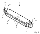
- FIG. 1 shows a perspective view of a connector assembly 1 with a connector 2 and a mating connector 3, which have a plug-in contour formed for mating and electrically conductive mating contacts of connector 2 and mating connector 3.
- the connector 2 has an insulating housing 4 accommodated therein, not visible plug contacts and with conductor insertion openings on the back (not visible).
- the conductor insertion openings are provided for insertion of electrical conductors to electrically introduced electrical conductor with an associated plug contact in the insulating z.
- B. by means of a spring clamp connection, a screw terminal, a cutting terminal connection or the like to contact.
- spring terminal contacts are arranged in the interior of the insulating material, which can be actuated for example with actuating means.
- the mating connector 3 is formed in the illustrated embodiment as a printed circuit board connector, protrude in the connection contacts 5 of the insulating 6 of the mating connector 3. These connection contacts 5 are connected to plug contacts in the interior of the insulating housing 6 of the mating connector 3 to electrically connected in the illustrated mated state in contact with corresponding plug contacts of the connector 2.
- the plug contour 7 of the connector 2 and the corresponding plug contour 8 of the mating connector 3 have z.
- the coding elements 9 then have a corresponding, adapted thereto contour to be mounted linearly displaceable in the dovetail guide. It is clear that the linear guides have in their end receiving pockets 10 with connecting elements 11 a, 11 b, with which in the longitudinal direction diametrically opposite and pointing in opposite directions facing each other free ends 12 a, 12 b of the coding elements 9 can be releasably connected by positive engagement.
- These connecting elements 11 a, 11 b of the receiving pockets 10 are formed, for example, as latching recesses which provide a latching stop for a dipped into the detent connection element 13 a, 13 b of a Kodieriatas 9, which may be formed for example by means of latching projections at the respective free end 12 a, 12 b as a latching finger ,
- a stop is formed by positive locking, which prevents a simple displacement of the coding element 9 without further application of force from the outside.
- the coding elements 9 are already inserted into the connector 2 or the mating connector 3 and there with their corresponding connecting elements 11 a, 13 a; 11 b, 13 b releasably connected to each other by positive engagement and / or by adhesion.
- the latching fingers ie, the connecting elements 13a, 13b
- the latching fingers are in the region of the connecting elements 11 a, 11 b of the receiving pockets 10 of the linear guides in the illustrated plug state accessible from the outside.
- a locking tab 14 is present on the side wall of the insulating housing 6 of the mating connector 3.
- a protruding latching lug 15 is arranged on the side wall of the insulating housing 4 of the connector 2. In the illustrated plug state, the protruding latching lug 15 dips into a latching opening 16 of the latching lug 14 in order to prevent undesired removal of the mating connector 3 from the plug connector 2 in this way.
- a latching tab 14 may also be present in addition to the opposite side of the mating connector 3. Accordingly, then a locking lug 15 is also present on the opposite side wall of the insulating housing 4 of the connector 2.
- the locking of the coding 9 is thus, as shown in FIG. 1 it can be seen, in the plug state allows, are plugged together in the connector 2 and mating connector 3 and an electrically conductive connection associated plug contacts is made thereby.
- FIG. 2 leaves a top view of the connector assembly 1 from FIG. 1 detect.
- the coding elements 9 are accessible from the outside in the illustrated plug state and in the respectively associated linear guide, of which only the receiving pockets 10 are visible, can be moved.
- the free ends 12a, 12b of the coding elements 9, which have the connecting elements 13a, 13b (ie the latching fingers), for. B. with a screwdriver with a displacement force are applied, so as to the releasable connection between the running as a latching finger and as a detent co-operating connecting elements 11 a, 13 a; 11 b, 13 b cancel and move the coding element 9 for releasable connection with the opposite connector 2 or mating connector 3.
- FIG. 3 lets a perspective view of a Kodieriatas 9 recognize.
- This coding element 9 is formed point-symmetrical in the illustrated embodiment.
- the coding element 9 is in principle designed as a rectangular rod extending in the longitudinal extension direction L, which diametrically oppose, at the opposite free ends 12a, 12b, a respective latching finger as a locking element 13a, 13b. laterally projecting locking projections 18 has.
- These opposing locking fingers with their locking projections 18 form connecting elements 13a, 13b, the releasable positive connection with the locking recesses (ie the connecting elements 11 a, 11 b) in the diametrically opposite receiving pockets 10 at the expiring ends of the linear guides of the connector 2 and mating connector 3 are provided.
- the locking projections 18 can be pressed into the associated, compared to the main section of the linear guide receiving pocket 10 at the end of the linear guides until they are in the associated locking recesses (ie, the connecting elements 11a, 11 b) immerse and there is provided a latching stop for the positive connection of the coding element 9 and the receiving pocket 10 of the linear guide.
- the latching fingers and latching recesses and latching hooks or latching tabs may be provided which cooperate with latching projections to provide a positive stop and possibly a frictional connection.
- latching recesses are provided at the free ends 12a, 12b of the coding elements 9, which can form a positive and / or non-positive connection with latching projections in the receiving pockets 10.
- the diametrically opposed side walls 19 of the coding elements 9 are formed to run obliquely to each other to form a guide contour, which is adapted to the contour of the linear guides.
- a groove is provided by the obliquely or curved side walls 19 on the diametrically opposite side walls 19 of the coding element 9, which provides a dovetail guide with the linear guide of the connector 2 and mating connector 3. It is still recognizable that on the side walls 19 offset in the longitudinal extension direction L on two different height levels, that is also arranged offset in height two holding nips 20 which protrude from the plane of the guide wall formed on the side wall 19.
- each two such holding nubs 20 On the diametrically opposite side of each two such holding nubs 20 are offset in height with respect to the top and bottom of the coding element 9 on a plane and arranged offset in the longitudinal direction L to each other.
- the holding nips 20 are arranged so that the coding element 9 is executed point-symmetrical.
- the coding element 9 can be used on the envelope, ie in any position without prior orientation in the linear guide.
- latching projections 18 of the latching fingers 13 provide an oval latching projection in cross section.
- FIG. 5 shows the coding element 9 in side view. It is clear that the two holding nubs 20 are arranged on one side in each case on two mutually offset planes arranged on the one hand adjacent to the top and on the other hand adjacent to the underside of the coding element 9.
- FIG. 6 leaves a front view of the coding element 9 FIGS. 3 to 5 detect. It is clear that at the diametrically opposite side walls 19 each have a V-shaped groove is formed by obliquely converging walls. Thus, a dovetail guide of the coding element 9 is provided.
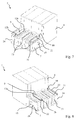
- FIG. 7 lets recognize a perspective view of the connector 2 of the connector assembly 1 with only one coding element 9. It is clear that this coding element 9 is formed in its length so that it can be moved in the inserted state of a mating connector 3 in the direction of mating connector 3. In the illustrated embodiment, the free end 12 b of the latched on the connector 2 coding element 9 ends at the free end of the plug contour 7 of the connector. 2
- linear guides 21 on the plug contour 7 on the top of the connector 2 retaining strips 22 have.
- each opposing and facing each other retaining strips 22 are arranged so that they dive into the guide contour of an inserted coding element 9 and hold the coding element 9 at least in the illustrated with the connector 2 locking position.
- the retaining strips 22 do not extend over the entire length of the linear guide 21 of the connector 2, but end in front of the free end of the connector 2.
- the retaining strips 22 engage only then to the holding nubs, when the coding element 9 in the direction of the connecting element 11 a, 11 b, ie in the direction of the detent recess in the receiving pocket 10 of the linear guide 21 is moved.
- This detent recess is arranged on both sides in the side walls of the receiving pockets 10 at the ends of the linear guide 21 forming groove.
- plug contacts 23 are arranged in the interior of the insulating housing.
- the plug contour 7 of insulating material integral, d. H. without joints formed with the insulating housing 4 protective sleeves 24 which surround the associated plug contacts 23.
- the mating connector 3 is now inserted with its corresponding plug contacts in the opening of the protective sleeves 24, so that the plug contacts of the mating connector 3 in the plug state electrically conductively come into contact with the plug contacts 23 of the connector 2.
- FIG. 8 leaves a perspective view of the connector 2 from FIG. 7 from the other side. It becomes clear that here too a latching lug 15 is arranged on the side wall of the insulating housing 4.
- Visible is also that at the compared to FIG. 7 Visible opposite side of the linear guide 21 is also a retaining strip 22 with a shortened length is present. The length of this retaining strip 22 is shorter than on the opposite side or vice versa. This is due to the holding knobs 20 arranged offset in the longitudinal direction L of the coding element 9 on a common plane.
- the linear guide 21 is then supplemented by a corresponding guide contour on the inside of the insulating housing 6 of the mating connector 3 to provide a dovetail guide. It is clear that the coding element 9 protrudes from the plane of the top of the plug contour 7 of the connector 2, which is formed by the protective sleeves 24.
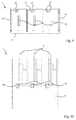
- FIG. 9 leaves a front view of the insertion of the mating connector 3 of the connector assembly 1 from FIGS. 1 and 2 detect. It is clear that on the inner wall of the upper side of the insulating housing 6, a linear guide 21 for each terminal pole, ie for each of the juxtaposed plug contacts 26 is present. These linear guides 21 are formed by a groove which widens conically towards the groove base and inclined, the retaining strips 27 having side walls. Thus, the upper, protruding from the plane of the plug-in contour 7 of the connector 2 part of a plugged onto the connector 2 coding element 9 are also guided displaceably on this linear guide 21. It is clear that this linear guide 21 passes into a locking element 11 b, which is set up in the formed as a blind hole receiving pocket 10 and for releasably connecting the coding element 9 by positive engagement and / or by frictional connection.
- plug contacts 26 of the mating connector 3 project as blade contacts in order to come into electrically conductive contact with opposite spring clips of the connector 2, which form a fork contact.
- FIG. 10 leaves a top view of the mating connector 3 FIG. 1 . 2 and 9 detect. It is clear that the linear guides 21 terminates in each case in the receiving pocket 10 with the latching element 11 b designed as a latching recess, the receiving pockets 10 being accessible from the upper side, ie being open. It can also be seen that a plurality of such linear guides 21 are arranged side by side. For each plug contact 26, a linear guide 21 is provided, wherein the linear guides 21 offset in the transverse direction to the longitudinal extension direction L of the associated plug contacts 26 and the associated connection contacts 5 are arranged.
- FIG. 11 leaves a perspective view of the mating connector 3 FIGS. 9 and 10 detect.
- the linear guides 21 formed by the conically tapering groove become clearer, which have inclined wall sections for forming a dovetail guide for a respectively inserted coding element 9.
- At the wall sections holding strips 27 are arranged.
- elastically resilient latching tabs 14 are provided on the diametrically opposite sides of the insulating housing 6.
- the perspective view FIG. 11 shows only the insulating housing 6 without the plug contacts used therein.
- FIG. 12 leaves a corresponding perspective detail view of the plug contour 7 of the connector 2 FIGS. 7 and 8 detect. It is clear that the retaining strips 22 narrow the receiving channel of the linear guide 21, so that the retaining strips 22 can force fit in conjunction with the holding nubs 20 of a coding element 9. It is clear that the diametrically opposed retaining strips 22 on the linear guide 21 have a different length, which are adapted to the position of the associated holding nips 20 so that either in the locking position on the connector 2 or in the locking position on the mating connector 3 a frictional connection between Connector 2 and coding element 9 or between mating connector 3 and coding element 9 is ensured.
- the retaining strips 22 are adapted to the holding nips 20 so that in no case a frictional connection between the coding element 9 and both the connector 2, and the mating connector 3 is made.
- the retaining strips 22 are arranged on the dovetail strips which provide the dovetail guide for the coding elements 9.
- FIG. 13 lets a cut-sectional view of the plug contour 8 of the mating connector 3 recognize. It becomes clear that a groove which is to be conically widened to the groove base is formed by the retaining strips 27. Thus, one half of a Kodieriatas 9 is taken with its holding contour, which is formed by the diametrically opposed inclined walls 19.
- a mating connector 3 facing the latching fingers ie, the free end 12a, 12b with the locking member 13a, 13b
- the receiving pocket 10 can then dive into the receiving pocket 10 and on the associated locking element 11a, 11b, which is formed by the detent recess in the receiving pocket 10, lock ,
- FIG. 14 lets recognize a side view of the mating connector 3. It is clear that on the side wall of the insulating material 6 of the mating connector 3, an elastically resilient locking tab 14 is cut free. This can be done by appropriate shaping during the injection molding process for producing the insulating housing 6 made of a plastic material.
- FIG. 15 leaves a perspective view of the connector 2 for the connector assembly 1 from FIG. 1 recognize in the delivery state with three coding elements 9, which are detachably connected to the insulating 4 of the connector 2.
- the locking fingers ie formed as locking elements 13a, 13b free ends 12a, 12b of the Kodieriatas 9 at the free end of the plug contour 7 opposite side into the locking elements 11 a, 11 b of the linear guide 21 and are secured there by a latching stop ,
- the coding elements 9 are thus connected in the delivery state captive with the connector 2 and do not need to be shipped separately as separate items that may be lost.
- FIG. 16 leaves a top view of the connector 2 FIG. 15 detect. It is clear that in each case a latching finger at the free end 12a, 12b of a coding element 9 in a narrow, the locking element 13a, 13b in the form of a detent groove having (ie in the receiving pocket 10) and there releasably positive fit and due to the elasticity of the above Locking projections 18 possibly also connected non-positively.
- the diametrically opposite locking element 13b is not positively and / or non-positively connected to the latching finger of the coding element 9.
- the opposite locking element 13b can be connected after displacement of a coding element 9 with a plugged mating connector 3.
- FIG. 17 leaves a front view on the Einsteckseite of the connector 2 FIGS. 15 and 16 detect. It is clear that the coding elements 9 are guided by a dovetail guide on the top of the protective sleeves 24 of the connector 2 linearly displaceable. It can also be seen that the plug contacts 23 are accessible from the front side through the interior of the protective sleeves 24 and configured as a diametrically opposite spring clip for receiving a contact blade in the intermediate space.
- the coding elements 9 or the linear guides 21 for the coding elements 9 are arranged laterally offset from the plug contacts 23. By different dislocations the coding possibilities can be increased.
- FIG. 18 leaves a side view of the connector 2 FIGS. 15 to 17 detect. This is again clear that on the side wall of the outer protective sleeves 24 and the plug contour 7, a latching lug 15 is arranged with obliquely tapered outflow in the plugging direction.
- FIG. 19 lets a perspective view of another embodiment of a coding element 9 recognize.
- a locking groove 30 extending in the longitudinal extension direction L of the coding element 9 is present on the upper side and on the lower side. This runs over the central area to the free ends 12a, 12b.
- the free ends 12a, 12b in turn - unlike the above-described embodiment - no locking elements, for example in the form of protrusions.
- the positive and / or non-positive connection of the coding element 9 either to a connector 2 or to a mating connector 3 by means of the locking grooves 30 by an associated locking lug 31 on the connector 2 or on the mating connector 3 in the locking groove 30 is immersed.
- FIG. 20 shows a perspective cutaway view of the plug contour of a connector 2 with coding elements 9 according to FIG. 19 , It is clear that at the bottom of the linear guide 21 in each case a locking lug 31 projects beyond the plane of the bottom of the linear guide 21. For a stop between the coding element 9 and the connector 2 is formed. In the same way, a locking lug 31 is also provided in the mating connector 3.
- the locking tabs 31 are arranged and matched to the length of the locking groove 30, that in the plug state, in which the mating connector 3 is plugged onto the connector 2, only one locking tab 31 is inserted into the locking groove 30. This ensures that the coding element 9 can not be connected simultaneously with the connector 2 and the mating connector 3.
- FIG. 21 shows a side sectional view of a latched on the plug contour of a connector 2 coding element 9. It is clear that the locking tab 31 is immersed in the state of positive connection in the locking groove 30 and forms a stop. A locking of the Kodieriatas 9 is only possible that a sufficient force in the longitudinal direction L is exerted on the coding element 9, that the provided by the locking tab 31 locking catch is overcome and the locking tab 31 is led out of the locking groove 30 so that the locking tab 31st is placed in front of the free end 12a, 12b of the coding element 9. In this position, however, then the diametrically opposite and arranged on the other upper side of the linear guide 21 Arretiernase 31 of the mating connector 3 (not shown) in the opposite locking groove 30 to positively connect the coding with the mating connector.
Landscapes
- Details Of Connecting Devices For Male And Female Coupling (AREA)
- Transmission And Conversion Of Sensor Element Output (AREA)
Description
Die Erfindung betrifft eine Steckverbinderanordnung mit einem Steckverbinder und einem Gegensteckverbinder, die jeweils ein Isolierstoffgehäuse und Steckkontakte in dem Isolierstoffgehäuse und korrespondierend zueinander zum Zusammenstecken und zum elektrisch leitenden Verbinden zugeordneter Steckkontakte im zusammengesteckten Zustand ausgestaltete Steckkonturen haben und mit mindestens einem Kodierelement, das verschiebbar an den Steckkonturen des Steckverbinders und Gegensteckverbinders aufnehmbar ist und eine zulässige Steckposition für das Zusammenstecken von Steckverbinder und Gegensteckverbinder festlegt.The invention relates to a connector assembly having a connector and a mating connector, each having a Isolierstoffgehäuse and plug contacts in the insulating material and corresponding to each other for mating and electrically conductive connecting associated plug contacts in the assembled state configured plug contours and having at least one coding element which is displaceable on the plug contours the connector and mating connector is receivable and defines an allowable plug position for the mating of connectors and mating connector.
Die Erfindung betrifft weiterhin ein Kodierelement für eine solche Steckverbinderanordnung sowie ein Verfahren zur Kodierung einer solchen Steckverbinderanordnung mit mindestens einem solchen Kodierelement.The invention further relates to a coding element for such a connector assembly and a method for coding such a connector assembly with at least one such Kodierelement.
Bei Steckverbinderanordnungen sind die Steckkonturen durch Ausformung der Isolierstoffgehäuse jeweils so passend aufeinander abgestimmt, dass ein Steckverbinder nur in einer zulässigen Steckposition mit einem Gegensteckverbinder verbunden werden kann und ein Fehlstecken sicher verhindert wird.In connector assemblies, the plug contours are matched by shaping the insulating material each match so that a connector can be connected only in a permissible plug position with a mating connector and miscarriage is reliably prevented.
Es gibt aber Einsatzbereiche, bei denen gleichartige Steckverbinder bzw. Gegensteckverbinder für unterschiedliche Funktionen genutzt werden und ein Vertauschen gleichartiger Steckverbinder sicher verhindert werden muss. Hierzu ist bekannt, die Steckverbinder und/oder Gegensteckverbinder mit separaten Kodierelementen zu versehen, die bedarfsweise an der Steckkontur der Isolierstoffgehäuse angebracht werden.But there are applications in which similar connectors or mating connectors are used for different functions and a swap of similar connectors must be reliably prevented. For this purpose, it is known to provide the connector and / or mating connector with separate coding elements, which are attached as needed to the mating contour of the insulating material.
Aus
Ausgehend hiervon ist es Aufgabe der vorliegenden Erfindung, eine verbesserte Steckverbinderanordnung sowie ein verbessertes Kodierelement sowie ein Verfahren zum Kodieren einer Steckverbinderanordnung zu schaffen.Based on this, it is an object of the present invention to provide an improved connector assembly and an improved coding and a method for encoding a connector assembly.
Die Aufgabe wird mit der Steckverbinder mit den Merkmalen des Anspruchs 1 sowie mit dem Kodierelement mit den Merkmalen des Anspruchs 13 sowie durch
das Verfahren mit den Merkmalen des Anspruchs 19 gelöst. Vorteilhafte Ausführungsformen sind in den Unteransprüchen beschrieben.The object is achieved with the connector with the features of claim 1 and with the coding element with the features of claim 13 and by
the method with the features of
Für eine aus einem Steckverbinder und einem Gegensteckverbinder sowie mindestens einem Kodierelement gebildete Steckverbinderanordnung wird vorgeschlagen, dass die Steckkonturen sowohl des Steckverbinders als auch des Gegensteckverbinders Verbindungselemente haben. Weiterhin hat das mindestens eine Kodierelement mindestens zwei voneinander beabstandete Verbindungselemente. Die Verbindungselemente des Kodierelementes sind zur lösbaren formschlüssigen und/ oder kraftschlüssigen Verbindung mit einem jeweils zugeordneten Verbindungselement des Steckverbinders oder Gegensteckverbinders ausgebildet. Das mindestens eine Kodierelement ist dabei von Außen in einem Zustand, bei dem der Steckverbinder und der Gegensteckverbinder zumindest teilweise zusammengesteckt sind, zugänglich und verschiebbar. Damit kann die formschlüssige lösbare Verbindung der zugeordneten Verbindungselemente von Kodierelement und Steckverbinder gelöst werden und das Kodierelement nach einer Verschiebung in Richtung des Gegensteckverbinders mittels der zugeordneten Verbindungselemente des Kodierelementes und des Gegensteckverbinders nunmehr mit dem Gegensteckverbinder verbunden werden.For a plug connector arrangement formed from a plug connector and a mating plug connector and at least one coding element, it is proposed that the plug contours of both the plug connector and the mating plug connector have connecting elements. Furthermore, the at least one coding element has at least two spaced connecting elements. The connecting elements of the coding element are designed for releasable positive and / or non-positive connection with a respective associated connecting element of the connector or mating connector. The at least one coding element is externally in a state in which the connector and the mating connector are at least partially plugged together, accessible and displaceable. Thus, the positive releasable connection of the associated connecting elements of the coding element and connector can be solved and the coding element now connected to a displacement in the direction of the mating connector by means of the associated connecting elements of the coding and the mating connector with the mating connector become.
Gemäß der Lehre der vorliegenden Erfindung ist das Kodierelement damit entweder mit dem Steckverbinder oder mit dem Gegensteckverbinder formschlüssig und/oder kraftschlüssig verbindbar. Diese formschlüssige Verbindung kann aufgehoben werden, um das Kodierelement wahlweise entweder mit dem Steckverbinder oder mit dem Gegensteckverbinder formschlüssig und/oder kraftschlüssig zu verbinden.According to the teachings of the present invention, the coding element can thus be connected to the plug-in connector or to the mating connector in a form-fitting and / or force-locking manner. This positive connection can be canceled to connect the coding optionally either with the connector or with the mating connector form-fitting and / or non-positively.
Das Kodierelement wird somit sozusagen umgerastet, um damit eine bestimmte Kodierung von Steckverbinder und Gegensteckverbinder festzulegen.The coding element is thus, so to speak, latched over in order to determine a specific coding of plug connector and mating connector.
Im Auslieferungszustand wird das Kodierelement form- und/oder kraftschlüssig verbunden am dem Steckverbinder oder Gegensteckverbinder ausgeliefert. Bei der ersten Inbetriebnahme kann dann ein Umrasten von mindestens einem ausgewählten Kodierelement erfolgen, das dann vom Steckverbinder gelöst und mit dem Gegensteckverbinder verbunden wird oder umgekehrt. Denkbar ist auch, dass vor dem Zusammenstecken ausgewählte, mit ausgelieferte und verbundene Kodierelemente vom Steckverbinder bzw. Gegensteckverbinder vollkommen entfernt werden. Das Verschieben und "Umrasten" des Kodierelementes wird dadurch ermöglicht, dass das Kodierelement jeweils ein Verbindungselement für den Steckverbinder und für den Gegensteckverbinder hat, die voneinander beabstandet sind. Die Verbindungselemente können sich hierzu beispielsweise in Längserstreckungsrichtung des Kodierelementes gegenüberliegen, d.h. an den diametral gegenüberliegenden Endbereichen des Kodierelementes angeordnet sein. Denkbar ist aber auch, dass sich die Verbindungselemente quer zur Längserstreckungsrichtung gegenüberliegen. Sie können dann bedarfsweise noch in Längserstreckungsrichtung beabstandet sein.In the delivery state, the coding element is positively and / or non-positively connected delivered to the connector or mating connector. At the first startup can then be a latching of at least one selected coding done, which is then released from the connector and connected to the mating connector or vice versa. It is also conceivable that selected before mating, with delivered and connected coding from the connector or mating connector are completely removed. The shifting and "snapping" of the coding element is made possible by the fact that the coding element has in each case a connecting element for the plug connector and for the mating plug connector, which are spaced apart from one another. For this purpose, the connecting elements may, for example, lie opposite one another in the longitudinal extension direction of the coding element, i. be arranged at the diametrically opposite end portions of the Kodierelementes. It is also conceivable that the connecting elements are opposite transversely to the longitudinal direction. You can then, if necessary, still be spaced in the longitudinal direction.
Das Kodierelement hat somit eine Führungskontur zur linear verschiebbaren Aufnahme an einem Steckverbinder und einem Gegensteckverbinder der Steckverbinderanordnung sowie voneinander beabstandete Verbindungselemente (z.B. an einander gegenüberliegenden Endabschnitten) zur lösbaren formschlüssigen und/oder kraftschlüssigen Verbindung mit einem jeweils zugeordneten Steckverbinder oder Gegensteckverbinder. Im zusammengesteckten Zustand von Steckverbinder und Gegensteckverbinder ist das Kodierelement somit entweder lösbar und form- und/oder kraftschlüssig mit dem Steckverbinder oder mit dem Gegensteckverbinder verbunden. Die Verbindung kann durch Verschiebung des Kodierelementes nach Aufhebung der lösbaren Verbindung gewechselt werden.The coding thus has a guide contour for linearly displaceable recording on a connector and a mating connector of Connector assembly and spaced apart connecting elements (eg at opposite end portions) for releasable positive and / or non-positive connection with a respective associated connector or mating connector. In the mated state of the connector and mating connector, the coding element is thus either releasably and positively and / or non-positively connected to the connector or with the mating connector. The connection can be changed by moving the coding element after the detachable connection has been removed.
Die Kodierung einer Steckverbinderanordnung erfolgt somit durch
- formschlüssiges und/oder kraftschlüssiges lösbares Verbinden des mindestens einen Kodierelementes an dem Steckverbinder;
- Zusammenstecken des Steckverbinders mit einem Gegensteckverbinder und
- Lösen der Verbindung mindestens eines ausgewählten Kodierelementes mit dem Steckverbinder, Verschieben des ausgewählten Kodierelementes in Richtung Gegensteckverbinder und formschlüssiges und/oder kraftschlüssiges lösbares Verbinden des ausgewählten Kodierelementes mit dem Gegensteckverbinder.
- positive and / or non-positive detachable connection of the at least one coding element to the connector;
- Mating the connector with a mating connector and
- Releasing the connection of at least one selected coding element with the connector, shifting the selected coding element in the direction of mating connector and positive and / or non-positive detachable connection of the selected coding element with the mating connector.
Die Kodierelemente können somit bereits werksseitig an einem ersten Steckverbinderbauteil montiert werden. Vom Nutzer kann die Kodierung je nach Bedarf individuell durch Verschieben und Verrasten der ausgewählten Kodierelemente an dem zweiten Steckverbinderbauteil eingestellt werden. Damit sind keine separaten Kodierelemente als vom Benutzer noch zu montierende Einzelteile mehr vorhanden.The coding elements can thus already be factory-mounted on a first connector component. From the user, the coding can be adjusted individually as required by moving and locking the selected coding on the second connector component. Thus, no separate coding elements are still available as user still to be assembled items.
Unter einem Steckverbinder wird ein Steckerteil oder Buchsenteil und unter einem Gegensteckverbinder das hierzu korrespondierende Steckverbinderteil, d. h. bei einem Stecker ein Buchsenteil oder bei einer Buchse das Steckerteil verstanden.Under a connector is a plug or socket part and under a mating connector corresponding thereto connector part, that is, in the case of a plug, a socket part or, in the case of a socket, the plug part.
Unter einer lösbaren Verbindung ist zu verstehen, dass das Verbindungselement des Steckerteils oder Gegensteckerteils so mit dem Verbindungselement des Kodierelementes ineinander greift, dass die beiden Verbindungspartner, nämlich der Steckverbinder oder Gegensteckverbinder und das hiermit verbundene Kodierelement nicht mehr ohne weiteres voneinander gelöst werden können. Dies gelingt z. B. dadurch, dass ein Abschnitt des einen Verbindungselementes einem Abschnitt des anderen Verbindungselementes bei Herausziehen des Kodierelementes im Weg steht und somit ein Anschlag, d.h. eine Verrastung gebildet wird. Denkbar ist aber auch, dass die Verbindung durch einen Kraftschluss bereitgestellt wird, bei der ein Verbindungselement eine Kraft auf das zugeordnete andere Verbindungselement ausübt. Dies kann beispielsweise durch einen Federarm des Kodierelementes erfolgen, der durch Reibschluss eine lösbare Verbindung zwischen Kodierelement und Steckverbinder bzw. Gegensteckverbinder bereitstellt. Denkbar ist aber auch eine Kombination einer formschlüssigen und einer kraftschlüssigen lösbaren Verbindung.Under a detachable connection is to be understood that the connecting element of the male part or mating connector engages with each other so that the connection element of the coding, that the two connection partners, namely the connector or mating connector and the associated coding element can not be easily solved from each other. This succeeds z. B. in that a portion of the one connecting element is a portion of the other connecting element upon withdrawal of the coding element in the way and thus a stop, i. a catch is formed. It is also conceivable that the connection is provided by a frictional connection, in which a connecting element exerts a force on the associated other connecting element. This can be done for example by a spring arm of the coding, which provides a releasable connection between the coding and connector or mating connector by frictional engagement. It is also conceivable, however, a combination of a positive and a non-positive releasable connection.
Die Verbindungselemente des Steckverbinders und des Gegensteckverbinders sind vorzugsweise als Rastmulden ausgebildet. Die Verbindungselemente des mindestens einen Kodierstiftes sind hingegen als Rastfinger ausgebildet. Die Rastfinger und Rastmulden haben dabei eine zum Einstecken eines Rastfingers in eine Rastmulde und zum lösbaren Verbinden des in die Rastmulde eingesteckten Rastfingers mittels eines Rastanschlages und/oder durch Kraftschluss angepasste Kontur. So ist denkbar, dass der Rastfinger in eine Rastmulde eingesteckt und mit Hilfe eines vorspringenden Abschnitts oder Federarms ein Reibschluss auf die Innenwand der Rastmulde ausgeübt wird. Dieser muss zum Lösen der Verbindung und Verschieben des Kodierelements überwunden werden. Eine solche Verschiebung kann z. B. mit Hilfe eines von Außen auf das Kodierelement einwirkenden Schraubendrehers erreicht werden.The connecting elements of the connector and the mating connector are preferably formed as latching recesses. The connecting elements of the at least one coding pin, however, are designed as latching fingers. The latching fingers and latching recesses have a plug for inserting a latching finger into a latching recess and for releasably connecting the latching finger inserted into the latching recess by means of a latching stop and / or by force fit contour. It is thus conceivable for the latching finger to be inserted into a latching recess and a frictional engagement to be exerted on the inner wall of the latching recess with the aid of a protruding section or spring arm. This must be overcome to release the connection and move the coding. Such a shift can z. B. can be achieved with the help of an externally acting on the coding screwdriver.
Das Kodierelement ist dabei dennoch immer noch so an dem Steckverbinder oder Gegensteckverbinder gesichert, dass es im nicht zusammengesteckten Zustand nicht ohne weiteres herausfällt.The coding element is still still secured to the connector or mating connector that it does not fall out easily in the unmated state.
Der Rastfinger und die Rastmulde können in einer anderen Ausführungsform aber auch einen Rastanschlag zur Ausbildung einer formschlüssigen Verbindung bilden. Hierzu kann der Rastfinger einen Rastvorsprung haben, der mit einer Vertiefung in der Rastmulde zusammenwirkt. Die Rastfinger erstrecken sich dabei vorzugsweise in Längserstreckungsrichtung des Kodierstiftes. Dabei ist vorzugsweise beidseits des Kodierstiftes an den einander diametral gegenüberliegende Enden jeweils ein Rastfinger vorhanden. Diese Rastfinger haben dabei seitlich vorstehende Rastvorsprünge, mit denen das Kodierelement lösbar und formschlüssig an dem zugeordneten Verbindungselement des Steckverbinders oder Gegensteckverbinders festgelegt werden kann.The latching finger and the detent recess can in another embodiment, however, also form a latching stop for forming a positive connection. For this purpose, the latching finger may have a latching projection which cooperates with a recess in the latching recess. The latching fingers preferably extend in the longitudinal extension direction of the coding pin. In this case, a latching finger is preferably present on both sides of the coding pin at the diametrically opposite ends. These latching fingers have laterally projecting latching projections, with which the coding can be releasably and positively fixed to the associated connection element of the connector or mating connector.
Die Rastmulden sind vorzugsweise als Nuten mit Vertiefungen an den Nutwänden zur Aufnahme zugeordneter Rastvorsprünge eines in die Rastmulde eingesteckten Rastfingers eines Kodierelementes ausgebildet.The latching recesses are preferably formed as grooves with recesses on the groove walls for receiving associated latching projections of a latching finger of a coding element inserted in the latching recess.
Denkbar ist aber auch eine umgekehrte Variante, bei der die Verbindungselemente des Steckverbinders und Gegensteckverbinders als Rastfinger und die Verbindungselemente des Kodierelementes als Rastmulden ausgebildet sind. Die Rastfinger und die Rastmulden haben dabei eine zum Einstecken eines Rastfingers in eine Rastmulde und zum lösbaren formschlüssigen und/oder kraftschlüssigen Verbinden des in eine Rastmulde eingesteckten Rastfingers mittels eines Rastanschlags und/oder durch Kraftschluss angepassten Kontur.It is also conceivable, however, a reverse variant, in which the connecting elements of the connector and mating connector are designed as latching fingers and the connecting elements of the coding element as latching recesses. The latching fingers and the detent recesses have a plug-in for engagement of a detent finger in a detent recess and for releasably positive and / or non-positive connection of the inserted into a detent detent finger by means of a locking stop and / or fit by force contour.
Eine weiter bevorzugte Ausführungsform sieht vor, dass das Kodierelement auf einander diametral gegenüberliegenden Seiten, die im eingesteckten Zustand einerseits dem Steckverbinder und andererseits dem Gegensteckverbinder zugewandt sind, jeweils eine sich in Längserstreckungsrichtung des Kodierelementes verlaufende Arretiernut hat. Von der angrenzenden Fläche des Steckverbinders und des Gegensteckverbinders ragen Arretiernasen ab. In Abhängigkeit der Steckposition ragt eine Arretiernase in eine zugeordnete Arretiernut hinein und bildet einen Anschlag, der das Kodierelement in der Steckposition entweder an dem Steckverbinder oder an dem Gegensteckverbinder sichert. Die andere Arretiernase ragt dabei nicht in die zugeordnete Arretiernut hinein.A further preferred embodiment provides that the coding element on diametrically opposite sides, which in the inserted state, on the one hand, face the plug connector and, on the other hand, the mating plug connector, each extend in the longitudinal extension direction of the coding element has running locking groove. From the adjacent surface of the connector and the mating connector protrude locking tabs. Depending on the insertion position, a locking tab projects into an associated locking groove and forms a stop which secures the coding element in the plug-in position either on the connector or on the mating connector. The other locking nose does not protrude into the associated locking groove.
Besonders vorteilhaft ist es, wenn die Steckkonturen des Steckverbinders und des Gegensteckverbinders Linearführungen zur linear verschiebbaren Aufnahme mindestens eines Kodierelementes haben.It when the plug contours of the connector and the mating connector linear guides for linearly displaceable receiving at least one coding have is particularly advantageous.
Das mindestens eine Kodierelement hat dann eine an die Linearführung angepasste Führungskontur. Damit wird das mindestens eine Kodierelement linear verschiebbar an einem Steckverbinder und dem Gegensteckverbinder gehalten und geführt.The at least one coding element then has a guide contour adapted to the linear guide. Thus, the at least one coding element is linearly displaceable held and guided on a connector and the mating connector.
Die Führungskontur des mindestens einen Kodierelementes und die Linearführungen können dabei bevorzugt eine Schwalbenschwanzführung bilden. Damit wird das Kodierelement nicht nur linear geführt sondern auch an einem Steckverbinder bzw. Gegensteckverbinder gehalten.The guide contour of the at least one coding element and the linear guides can preferably form a dovetail guide. Thus, the coding element is not only guided linearly but also held on a connector or mating connector.
Die Schwalbenschwanzführung kann dadurch realisiert werden, dass das Kodierelement auf einander gegenüberliegenden Seitenflächen jeweils eine sich in Längserstreckungsrichtung des Kodierelementes erstreckenden Nut mit schräg oder gekrümmt aufeinander zu verlaufenden Wänden hat.The dovetail guide can be realized in that the coding on each opposite side surfaces each have a extending in the longitudinal direction of the Kodierelementes groove with obliquely or curved towards each other to running walls.
Besonders vorteilhaft ist es, wenn das mindestens eine Kodierelement an einander gegenüberliegenden Seiten vorstehende Haltenoppen hat. Die Linearführungen weisen dabei einen Halteabschnitt auf, in dem eine durch die Linearführung gebildete Halteleiste kraftschlüssig an einem zugeordneten Haltenoppen eines eingeführten und mit dem Steckverbinder oder Gegensteckverbinder verbundenen Kodierstiftes anliegt. Die Linearführungen haben weiterhin einen verbreiterten Entnahmeabschnitt, in dem die Linearführung nicht im Eingriff mit einem zugeordneten Haltenoppen steht. Durch die kraftschlüssige Verbidnung der mindestens einen Halteleiste des Steckverbinders mit einer zugeordneten Haltenoppe des Kodierelementes wird das Kodierelement mit dem Steckverbinder verbunden. Dann besteht auch im Steckzustand des Gegensteckverbinders, der auf dem Steckverbinder aufgesteckt ist, keine form- und/oder kraftschlüssige Verbindung des Kodierelementes mit dem Gegensteckverbinder. Erst durch Umrasten kann bei Verschiebung des Kodierelementes die kraftschlüssige Verbindung mit dem Steckverbinder aufgehoben und eine kraftschlüssige Verbindung von Halteleisten des Gegensteckverbinders mit zugeordneten Haltenoppen des Kodierelementes hergestellt werden. Nach Verschiebung des Kodierelementes und Verbindung mit dem Steckverbinder oder Gegensteckverbinder wird der Haltenoppen somit in eine Position verlagert, bei der er kraftschlüssig an der Halteleiste im schmaleren Halteabschnitt anliegt.It is particularly advantageous if the at least one coding element has holding nubs projecting on opposite sides. The linear guides have a holding section, in which a retaining strip formed by the linear guide non-positively on an associated holding nubs of an inserted and with the connector or mating connector connected coding pin is applied. The linear guides also have a widened removal section, in which the linear guide is not in engagement with an associated holding nubs. Due to the frictional connection of the at least one retaining strip of the connector with an associated holding knob of the coding the coding element is connected to the connector. Then there is also in the plug state of the mating connector which is plugged on the connector, no positive and / or non-positive connection of the coding with the mating connector. Only by snapping the non-positive connection with the connector can be repealed upon displacement of the coding element and a frictional connection of retaining strips of the mating connector are produced with associated holding nubs of the coding. After displacement of the coding and connection with the connector or mating connector of the holding nubs is thus displaced into a position in which it rests non-positively on the retaining strip in the narrow holding portion.
Dabei ist es besonders vorteilhaft, wenn an den diametral gegenüberliegenden Seitenwänden jeweils zwei Haltenoppen vorhanden sind. Die Paare von Haltenoppen sind dann an einer Seitenwand jeweils höhenversetzt sowie in Längserstreckungsrichtung des Kodierelementes versetzt zueinander angeordnet. Damit ist die Einsteckrichtung und Einstecklage des Kodierelementes beliebig.It is particularly advantageous if two holding nubs are present on the diametrically opposite side walls. The pairs of holding nubs are then each offset in height on a side wall and arranged offset to one another in the longitudinal direction of the Kodierelementes. Thus, the insertion and insertion position of the coding is arbitrary.
Das mindestens eine Kodierelement ist besonders vorteilhaft spiegel- oder punktsymmetrisch ausgestaltet, so dass das Kodierelement unbeschadet der Einsteckrichtung und der Orientierung in eine zugeordnete Linearführung des Steckverbinders oder Gegensteckverbinders eingeschoben und dort verrastet werden kann.The at least one coding element is particularly advantageously designed mirror-symmetrical or point-symmetrical, so that the coding element can be inserted into an associated linear guide of the connector or mating connector without damage to the insertion direction and the orientation and latched there.
Unter "Verrasten" wird ein lösbares Verbinden im weitestgehenden Sinne verstanden, wie ein formschlüssiges Verbinden, z. B. mit Hilfe eines Anschlages, ein kraftschlüssiges Verbinden oder eine Kombination hiervon.By "latching" is meant a releasable connection in the broadest sense, such as a positive connection, for. B. by means of a stop, a frictional connection or a combination thereof.
Die Erfindung wird nachfolgend anhand eines Ausführungsbeispiels mit den beigefügten Zeichnungen näher erläutert. Es zeigen:
- Figur 1
- - perspektivische Ansicht einer Steckverbinderanordnung mit einem Steckverbinder, einem Gegensteckverbinder und mit verschiebbaren Kodierelementen;
Figur 2- - Draufsicht auf die Steckverbinderanordnung aus
Figur 1 ; Figur 3- - perspektivische Ansicht eines Kodierelementes für die Steckverbinderanordnung aus
Figur 1 und2 ; Figur 4- - Draufsicht auf das
Kodierelement auf Figur 3 , Figur 5- - Seitenansicht des Kodierelementes aus
Figur 3 und4 ; Figur 6- - Frontansicht des Kodierelementes aus
Figuren 3 ;bis 5 Figur 7- - perspektivische Ansicht des Steckverbinders der Steckverbinderanordnung aus
Figur 1 mit einem Kodierelement; Figur 8- - perspektivische Ansicht des Steckverbinders aus
Figur 7 von der anderen Seite; Figur 9- - Frontansicht der Einsteckseite des Gegensteckverbinders der Steckverbinderanordnung aus
Figur 1 und2 ; Figur 10- - Draufsicht auf den
Gegensteckverbinder aus Figur 9 ; Figur 11- - perspektivische Ansicht des Gegensteckverbinders aus
Figuren 9 ;und 10 - Figur 12
- - perspektivische Ausschnittsansicht der Steckkontur des Steckverbinders aus
Figur 7 und 8 ; - Figur 13
- - Ausschnitts-Schnittansicht des Steckkontur des Gegensteckverbinders;
Figur 14- - Seitenansicht des Gegensteckverbinders mit Rastlasche;
Figur 15- - perspektivische Ansicht eines Steckverbinders für die Steckverbinderanordnung aus
Figur 1 im Auslieferungszustand mit drei Kodierelementen; Figur 16- - Draufsicht auf den
Steckverbinder aus Figur 15 ; Figur 17- - Frontansicht auf die Einsteckseite des Steckverbinders aus
Figuren 15 ;und 16 Figur 18- - Seitenansicht des Steckverbinders aus
Figuren 15 ;bis 17 Figur 19- - perspektivische Ansicht einer weiteren Ausführungsform eines Kodierelementes;
Figur 20- - Perspektivische Ausschnittsansicht der Steckkontur eines Steckverbinders mit
Kodierelementes gemäß Figur 19 ; Figur 21- - Seiten-Schnittansicht eines an der Steckkontur eines Steckverbinders verrastetem Kodierelementes.
- FIG. 1
- - Perspective view of a connector assembly with a connector, a mating connector and with sliding coding elements;
- FIG. 2
- - Top view of the connector assembly from
FIG. 1 ; - FIG. 3
- - Perspective view of a coding element for the connector assembly
FIG. 1 and2 ; - FIG. 4
- - Top view of the coding on
FIG. 3 . - FIG. 5
- - Side view of the coding from
FIG. 3 and4 ; - FIG. 6
- - Front view of the coding element off
FIGS. 3 to 5 ; - FIG. 7
- - Perspective view of the connector of the connector assembly
FIG. 1 with a coding element; - FIG. 8
- - Perspective view of the connector
FIG. 7 from the other side; - FIG. 9
- - Front view of the insertion of the mating connector of the connector assembly
FIG. 1 and2 ; - FIG. 10
- - Top view of the mating connector
FIG. 9 ; - FIG. 11
- - Perspective view of the mating connector
FIGS. 9 and 10 ; - FIG. 12
- - Sectional perspective view of the plug contour of the connector
FIGS. 7 and 8 ; - FIG. 13
- - Sectional sectional view of the plug contour of the mating connector;
- FIG. 14
- - Side view of the mating connector with locking tab;
- FIG. 15
- - Perspective view of a connector for the connector assembly
FIG. 1 in delivery state with three coding elements; - FIG. 16
- - Top view of the connector off
FIG. 15 ; - FIG. 17
- - Front view of the plug-in side of the connector
FIGS. 15 and 16 ; - FIG. 18
- - Side view of the connector
FIGS. 15 to 17 ; - FIG. 19
- - Perspective view of another embodiment of a coding element;
- FIG. 20
- - Perspektivische part view of the plug contour of a connector with coding according to
FIG. 19 ; - FIG. 21
- - Side sectional view of a latched on the plug contour of a connector coding element.
Die Steckkontur 7 des Steckverbinders 2 sowie die korrespondierende Steckkontur 8 des Gegensteckverbinders 3 haben z. B. an ihrer Oberseite nicht sichtbare Linearführungen zur linear verschiebbaren Aufnahme mindestens eines Kodierelementes 9. Diese Linearführungen sind in dem dargestellten Ausführungsbeispiel als Nut mit schräg verlaufenden Abschnitten der Seitenwände ausgebildet, um eine Schwalbenschwanzführung zu bilden. Denkbar ist auch eine T-Nut als Führungsprofil oder ähnliches.The
Die Kodierelemente 9 haben dann eine entsprechende, hieran angepasste Kontur, um in der Schwalbenschwanzführung linear verschiebbar gelagert zu werden. Deutlich wird, dass die Linearführungen in ihren Endbereichen Aufnahmetaschen 10 mit Verbindungselementen 11 a, 11 b haben, mit denen die sich in Längserstreckungsrichtung diametral gegenüberliegenden und in entgegengesetzte Richtungen voneinander weisenden freien Enden 12a, 12b der Kodierelemente 9 durch Formschluss lösbar verbunden werden können. Diese Verbindungselemente 11 a, 11 b der Aufnahmetaschen 10 sind beispielsweise als Rastmulden ausgebildet, die einen Rastanschlag für ein in die Rastmulde eingetauchtes Verbindungselement 13a, 13b eines Kodierelementes 9 bereitstellen, welches beispielsweise mittels Rastvorsprüngen am jeweiligen freien Ende 12a, 12b als Rastfinger ausgebildet sein kann. Damit wird durch Formschluss ein Anschlag gebildet, der ein einfaches Verschieben des Kodierelementes 9 ohne weitere Kraftbeaufschlagung von Außen verhindert.The
Im Auslieferungszustand werden die Kodierelemente 9 bereits in den Steckverbinder 2 oder den Gegensteckverbinder 3 eingesetzt und dort mit ihren korrespondierenden Verbindungselementen 11 a, 13a; 11 b, 13b miteinander durch Formschluss und/oder durch Kraftschluss lösbar verbunden. Die Rastfinger (d.h. die Verbindungselemente 13a, 13b) sind im Bereich der Verbindungselemente 11 a, 11 b der Aufnahmetaschen 10 der Linearführungen in dem dargestellten Steckzustand von Außen zugänglich. Damit kann ein Kodierelement 9 bedarfsweise "umgerastet" werden, indem z. B. mit Hilfe eines Schraubendrehers der Formschluss und/oder Kraftschluss zwischen Kodierelement 9 und Verbindungselement 13a bzw. 13b aufgehoben wird und das Kodierelement 9 zu dem gegenüberliegenden Verbindungselement 13b bzw. 13a zur dortigen Verrastung (d. h. lösbaren formschlüssigen und/oder kraftschlüssigen Verbindung) in der Linearführung verschoben wird. Dies ist in dem dargestellten Ausführungsbeispiel derart erfolgt, dass das in Blickrichtung vordere Kodierelement 9 zum Gegensteckverbinder 3 hin umgerastet und nunmehr mit dem Gegensteckverbinder 3 verbunden ist. Die anderen beiden Kodierelemente 9n sind hingegen immer noch wie im Auslieferungszustand mit dem Steckverbinder 2 verbunden. Damit wird eine Kodierung von Steckverbinder 2 und Gegensteckverbinder 3 erreicht, die ein Zusammenstecken nur eines entsprechend kodierten Steckverbinders 2 mit dem Gegensteckverbinder 3 erlaubt und somit ein Fehlstecken von nicht zueinander passenden Steckverbindern 2 und Gegensteckverbindern 3 verhindert.In the delivery state, the
Erkennbar ist weiterhin, dass an der Seitenwand des Isolierstoffgehäuses 6 des Gegensteckverbinders 3 eine Rastlasche 14 vorhanden ist. An der Seitenwand des Isolierstoffgehäuses 4 des Steckverbinders 2 ist eine vorstehende Rastnase 15 angeordnet. Im dargestellten Steckzustand taucht die vorstehende Rastnase 15 in eine Rastöffnung 16 der Rastlasche 14 ein, um auf diese Weise ein ungewünschtes Abziehen des Gegensteckverbinders 3 vom Steckverbinder 2 zu verhindern. Eine solche Rastlasche 14 kann auch zusätzlich auf der gegenüberliegenden Seite des Gegensteckverbinders 3 vorhanden sein. Entsprechend ist dann auch an der gegenüberliegenden Seitenwand des Isolierstoffgehäuses 4 des Steckverbinders 2 eine Rastnase 15 vorhanden.It can also be seen that on the side wall of the insulating
Das Umrasten der Kodierelemente 9 wird somit, wie aus der
Deutlich wird auch, dass in dem dargestellten Rastzustand die Rastlasche 14 bündig mit der Seitenwand des Isolierstoffgehäuses 6 des Gegensteckverbinders 3 abschließt und die Rastnase 15 des Steckverbinders 2 etwas aus der Ebene des Oberfläche der Rastlasche 14 hinausragt. Dabei sind diametral einander gegenüberliegend an beiden Seitenwänden des Steckverbinders 2 solche Rastnasen 15 und an dem Gegensteckverbinder 3 entsprechende Rastlaschen 14 vorhanden.It is also clear that in the illustrated locking state, the
Dadurch, dass die Kodierelemente 9 aus einem elastisch verformbaren Kunststoffmaterial gebildet sind, können die Rastvorsprünge 18 in die zugeordnete, im Vergleich zum Hauptabschnitt der Linearführung schmalere Aufnahmetasche 10 am Ende der Linearführungen eingepresst werden, bis sie in die zugeordneten Rastmulden (d.h. den Verbindungselementen 11a, 11 b) eintauchen und dort ein Rastanschlag zum formschlüssigen Verbinden von Kodierelement 9 und Aufnahmetasche 10 der Linearführung bereitgestellt wird. Alternativ können anstelle der Rastfinger und Rastmulden auch Rasthaken oder Rastlaschen vorgesehen sein, die mit Rastvorsprüngen zusammenwirken, um einen formschlüssigen Anschlag und ggf. eine kraftschlüssige Verbindung bereitstellen. Denkbar ist auch eine umgekehrte Variante, bei der Rastmulden an den freien Enden 12a, 12b der Kodierelemente 9 vorhanden sind, die eine form- und/oder kraftschlüssige Verbindung mit Rastvorsprüngen in den Aufnahmetaschen 10 eingehen können.Characterized in that the
Deutlich wird weiterhin, dass die diametral einander gegenüberliegenden Seitenwände 19 der Kodierelemente 9 schräg zueinander verlaufend ausgebildet sind, um eine Führungskontur zu bilden, die an die Kontur der Linearführungen angepasst ist. Im dargestellten Ausführungsbeispiel wird durch die schräg oder gekrümmt verlaufenden Seitenwände 19 an den diametral gegenüberliegenden Seitenwänden 19 des Kodierelementes 9 eine Nut geschaffen, die eine Schwalbenschwanzführung mit der Linearführung des Steckverbinders 2 und Gegensteckverbinders 3 bereitstellt. Erkennbar ist weiterhin, dass an den Seitenwänden 19 in Längserstreckungsrichtung L versetzt auf zwei unterschiedlichen Höhenebenen, d. h. auch höhenversetzt jeweils zwei Haltenoppen 20 angeordnet sind, die von der Ebene der an der Seitenwand 19 ausgebildeten Führungskontur hervorstehen. Auf der diametral gegenüberliegenden Seite sind jeweils zwei solche Haltenoppen 20 im Bezug auf die Oberseite und Unterseite des Kodierelementes 9 auf einer Ebene höhenversetzt und in Längserstreckungsrichtung L versetzt zueinander angeordnet. Die Haltenoppen 20 sind dabei so angeordnet, dass das Kodierelement 9 punktsymmetrisch ausgeführt ist.It is also clear that the diametrically
Aus der Draufsicht auf
Deutlich wird weiterhin, dass die Rastvorsprünge 18 der Rastfinger 13 im Querschnitt einen ovalen Rastvorsprung bereitstellen.It is also clear that the latching
Deutlich wird weiterhin, dass die nunmehr sichtbaren Linearführungen 21 an der Steckkontur 7 auf der Oberseite des Steckverbinders 2 Halteleisten 22 haben. In der Linearführung 21 sind jeweils einander gegenüberliegende und auf einander zu weisende Halteleisten 22 so angeordnet, dass diese in die Führungskontur eines eingeführten Kodierelementes 9 eintauchen und das Kodierelement 9 zumindest in der dargestellten mit dem Steckverbinder 2 verbunden Rastposition halten.It is also clear that the now visible
Erkennbar ist weiterhin, dass die Halteleisten 22 sich nicht über die gesamte Länge der Linearführung 21 des Steckverbinders 2 erstrecken, sondern vor dem freien Ende des Steckverbinders 2 enden. Die Halteleisten 22 greifen erst dann an die Haltenoppen an, wenn das Kodierelement 9 in Richtung Verbindungselement 11 a, 11 b, d. h. in Richtung der Rastmulde in der Aufnahmetasche 10 der Linearführung 21 verschoben wird. Diese Rastmulde ist beidseits in den Seitenwänden der Aufnahmetaschen 10 an den Enden der die Linearführung 21 bildenden Nut angeordnet.It can be seen further that the retaining strips 22 do not extend over the entire length of the
Erkennbar ist weiterhin, dass im Innenraum des Isolierstoffgehäuses 4 Steckkontakte 23 angeordnet sind. Hierzu hat die Steckkontur 7 aus Isolierstoffmaterial integral, d. h. fügestellenfrei mit dem Isolierstoffgehäuse 4 gebildete Schutzhülsen 24, die die zugeordneten Steckkontakte 23 umgeben. Der Gegensteckverbinder 3 wird nun mit seinen korrespondierenden Steckkontakten in die Öffnung der Schutzhülsen 24 eingeführt, so dass die Steckkontakte des Gegensteckverbinders 3 im Steckzustand elektrisch leitend in Kontakt mit den Steckkontakten 23 des Steckverbinders 2 treten.It can also be seen that 4
Erkennbar ist auch, dass an der im Vergleich zu
Die Linearführung 21 wird dann durch eine entsprechende Führungskontur auf der Innenseite des Isolierstoffgehäuses 6 des Gegensteckverbinders 3 ergänzt, um eine Schwalbenschwanzführung bereitzustellen. Deutlich wird, dass das Kodierelement 9 aus der Ebene der Oberseite der Steckkontur 7 des Steckverbinders 2, die durch die Schutzhülsen 24 gebildet wird, hinausragt.The
Erkennbar ist auch, dass die Steckkontakte 26 des Gegensteckverbinders 3 als Messerkontakte hervorstehen, um mit einander gegenüberliegenden Federbügeln des Steckverbinders 2, die einen Gabelkontakt bilden, in elektrisch leitenden Kontakt zu treten.It can also be seen that the
Erkennbar ist auch, dass für jeden Pol, d. h. für jeden Steckkontakt jeweils eine eigene Schutzhülse 24 vorhanden ist. In dem Zwischenraum 28 zwischen zwei aneinander angrenzenden Schutzhülsen 24 ist eine Zwischenwand 29 des Gegensteckverbinders 3 (vgl.
Ein dem Gegensteckverbinder 3 zugewandter Rastfinger (d.h. das freie Ende 12a, 12b mit dem Verriegelungselement 13a, 13b) kann dann in die Aufnahmetasche 10 eintauchen und an dem zugeordneten Verriegelungselement 11a, 11 b, das durch die Rastmulde in der Aufnahmetasche 10 gebildet ist, verrasten.A
Weiterhin wird deutlich, dass die Kodierelemente 9 bzw. die Linearführungen 21 für die Kodierelemente 9 seitlich versetzt zu den Steckkontakten 23 angeordnet sind. Durch unterschiedliche Versetzungen können die Kodiermöglichkeiten erhöht werden.Furthermore, it becomes clear that the
Erkennbar ist weiterhin, dass die Kodierelemente 9 über die Ebene der Oberseite der Schutzhülsen 24, d. h. der Steckkontur 7 hinaus ragen, um mit einer Linearführung des Gegensteckverbinders 3 zusammenzuwirken.It can also be seen that the
Claims (19)
- Plug-type connector arrangement (1) comprising a plug-type connector (2) and an opposing plug-type connector (3), which each have an insulating housing (4, 6) and plug-type contacts (23, 26) in the insulating housing (4, 6) as well as plug-type contours (7, 8) configured correspondingly to one another for plugging together and for electrically conductively connecting assigned plug-type contacts (23, 26) in the plugged-together plugging state, and comprising at least one coding element (9), which can be accommodated displaceably on the plug-type contours (7, 8) of the plug-type connector (2) and opposing plug-type connector (3) and fixes a permissible plug-in position for plugging together the plug-type connector (2) and the opposing plug-type connector (3), characterized in that the plug-type contours (7, 8) both of the plug-type connector (2) and of the opposing plug-type connector (3) have connecting elements (11 a, 11 b, 22; 31), in that the at least one coding element (9) has at least two connecting elements (13a, 13b; 20; 30) which are spaced apart from one another, wherein the connecting elements (13a, 13b; 20; 30) of the coding element (9) are designed to be detachably connected in a form-fitting and/or force-fitting manner to a respectively assigned connecting element (11a, 11b; 22; 31) of the plug-type connector (2) or the opposing plug-type connector (3), and in that the at least one coding element (9) is accessible and displaceable from the outside in the state in which the plug-type connector (2) and the opposing plug-type connector (3) are at least partially plugged together, in order to detach a connection of the assigned connecting elements (11 a, 11b, 13a, 13b; 20, 22; 30, 31) from the coding element (9) and the plug-type connector (2) and in order to connect the coding element (9), once it has been displaced in the direction of the opposing plug-type connector (3), to the opposing plug-type connector (3) by means of the assigned connecting elements (11 a, 11b, 13a, 13b; 20, 22; 30, 31) of the coding element (9) and the opposing plug-type connector (3).
- Plug-type connector arrangement (1) according to Claim 1, characterized in that the connecting elements (11 a, 11 b) of the plug-type connector (2) and the opposing plug-type connector (3) have as latching troughs and the connecting elements (13a, 13b) of the at least one coding element (9) have as latching fingers with a contour which is adapted for entering a respectively assigned latching trough and for detachable connection in a form-fitting and/or force-fitting manner and in a manner secured against withdrawal.
- Plug-type connector arrangement (1) according to Claim 2, characterized in that the latching fingers extend in the direction of longitudinal extent (L) of the coding element (9) and have laterally protruding latching projections (18).
- Plug-type connector arrangement (1) according to Claim 3, characterized in that the latching troughs are in the form of depressions in side walls of receiving pockets (10) for receiving assigned latching projections (18) of a latching finger, inserted into the receiving pocket (10) of a coding element (9).
- Plug-type connector arrangement (1) according to one of the preceding claims, characterized in that the connecting elements (11 a, 11b) of the plug-type connector (2) and the opposing plug-type connector (3) are in the form of latching fingers and the connecting elements (13a, 13b) of the coding element (9) are in the form of latching troughs, wherein the latching fingers and the latching troughs have a contour which is adapted for insertion of a latching finger into a latching trough and for detachable form-fitting connection of the latching finger, inserted into a latching trough, by means of a latching stop and/or by a force-fitting connection.
- Plug-type connector arrangement (1) according to one of the preceding claims, characterized in that the plug-type contours (7, 8) of the plug-type connector (2) and the opposing plug-type connector (3) have linear guides (21) for receiving, in linearly displaceable fashion, at least one coding element (9), and in that the at least one coding element (9) has a guide contour which is matched to the linear guides (21).
- Plug-type connector arrangement (1) according to Claim 6, characterized in that the guide contour of the at least one coding element (9) and the linear guides (21) form a dovetail guide.
- Plug-type connector arrangement (1) according to Claim 7, characterized in that the coding element (9) has, on mutually opposite side faces, a groove which extends in each case in the direction of longitudinal extent (L) of the coding element and has sloping or curved walls (19).
- Plug-type connector arrangement (1) according to one of the preceding claims, characterized in that the at least one coding element (9) has, on mutually opposite sides, protruding holding knobs (20), and in that the linear guides (21) have a connecting section, in which a holding strip (22) formed by the linear guide (21) can connect, in a force-fitting manner, an assigned holding knob (20) of an inserted coding element (9), which is connected to the plug-type connector (2) or opposing plug-type connector (3), and a guide section, in which the linear guide (21) is connected in a force-fitting manner to an assigned holding knob (20).
- Plug-type connector arrangement (1) according to Claim 9, characterized in that in each case two holding knobs (20) are on the diametrically opposite side walls (19) of the coding elements (9), wherein the pairs of holding knobs (20) are arranged on a side wall (19) in each case so as to be vertically offset and offset with respect to one another in the direction of longitudinal extent (L) of the coding element (9).
- Plug-type connector arrangement (1) according to one of the preceding claims, characterized in that the coding element (9) has in each case a locking groove (30) on the upper side of said coding element and the diametrically opposite lower side, said locking groove extending in the direction of longitudinal extent (L) of the coding element (9), and in that the plug-type connector (2) and the opposing plug-type connector (3) each have at least one projecting locking lug (31), wherein the locking grooves (30) and the locking lugs (31) are arranged in order to connect the coding element either on the plug-type connector (2) by virtue of inserting the locking lug (31) of the plug-type connector (2) into an assigned locking groove (30) or on the opposing plug-type connector (3) by virtue of inserting the locking lug (31) of the opposing plug-type connector (3) into an assigned locking groove (30).
- Plug-type connector arrangement (1) according to one of the preceding claims, characterized in that the at least one coding element (9) is mirror-symmetrical or point-symmetrical.
- Coding element (9) for a plug-type connector arrangement (1) according to one of the preceding claims, characterized in that the coding element (9) has a guide contour for receiving, in linearly displaceable fashion, on a plug-type connector (2) and an opposing plug-type connector (3) of the plug-type connector arrangement (1) and at least two connecting elements (13a, 13b; 20; 30), which are spaced apart from one another, for detachable connection, in a form-fitting and/or force-fitting manner, to a respectively assigned connecting element (11 a, 11b; 22; 31) of a plug-type connector (2) or an opposing plug-type connector (3).
- Coding element (9) according to Claim 13, characterized in that the connecting elements (13a, 13b) of the coding element (9) is in the form of latching fingers at the mutually opposite free ends (12a, 12b) for entering into an assigned receiving pocket (10) of a plug-type connector (2) or opposing plug-type connector (3) and for form-fitting and/or force-fitting connection to at least one latching trough of the receiving pocket (10) or a latching projection and has laterally protruding latching projections (18), latching tabs or latching hooks.
- Coding element (9) according to either of Claims 13 and 14, characterized in that the coding element (9) has, on mutually opposite side faces, a groove extending in the direction of longitudinal extent (L) of the coding elements (9) and having walls (19) which run towards one another with a slope or curvature.
- Coding element (9) according to one of Claims 13 to 15, characterized in that the coding element (9) has two holding knobs (20) on the diametrically opposite sides, wherein the pairs of holding knobs (20) are in each case arranged on a side wall (19) so as to be vertically offset and offset with respect to one another in the direction of longitudinal extent (L) of the coding elements (9).
- Coding element (9) according to one of Claims 13 to 16, characterized in that the coding element (9) has, on its upper side and on the diametrically opposite lower side, in each case one locking groove (30), which extends in the direction of longitudinal extent (L) of the coding element (9).
- Coding element (9) according to one of Claims 13 to 17, characterized in that the coding element (9) is mirror-symmetrical or point-symmetrical.
- Method for coding a plug-type connector arrangement (1) according to one of Claims 1 to 12 comprising at least one coding element (9), characterized by:- detachably connecting, in a form-fitting and/or force-fitting manner, the at least one coding element (9) to the plug-type connector (2);- plugging together the plug-type connector (2) with an opposing plug-type connector (3), and- detaching the connection between at least one selected coding element (9) and the plug-type connector (2), displacing the selected coding element (9) in the direction of the opposing plug-type connector (3) and detachably connecting, in a form-fitting and/or force-fitting manner, the selected coding element (9) to the opposing plug-type connector (3).
Applications Claiming Priority (1)
| Application Number | Priority Date | Filing Date | Title |
|---|---|---|---|
| DE102014107948.5A DE102014107948B3 (en) | 2014-06-05 | 2014-06-05 | Connector assembly and coding element and method for encoding a connector assembly |
Publications (2)
| Publication Number | Publication Date |
|---|---|
| EP2953213A1 EP2953213A1 (en) | 2015-12-09 |
| EP2953213B1 true EP2953213B1 (en) | 2016-09-21 |
Family
ID=53284111
Family Applications (1)
| Application Number | Title | Priority Date | Filing Date |
|---|---|---|---|
| EP15170670.2A Active EP2953213B1 (en) | 2014-06-05 | 2015-06-04 | Connector assembly and encoding element for same and method for encoding a connector assembly |
Country Status (5)
| Country | Link |
|---|---|
| US (1) | US9537259B2 (en) |
| EP (1) | EP2953213B1 (en) |
| CN (1) | CN105161901B (en) |
| DE (1) | DE102014107948B3 (en) |
| PL (1) | PL2953213T3 (en) |
Families Citing this family (7)
| Publication number | Priority date | Publication date | Assignee | Title |
|---|---|---|---|---|
| DE102016116081A1 (en) * | 2016-08-29 | 2018-03-01 | Kathrein-Werke Kg | Holding and / or mounting frame, which is formed on or in a mobile radio antenna and / or on or in an electronic and / or filter module or fastened thereto, and an associated mobile radio antenna |
| CN108695636B (en) * | 2018-04-19 | 2020-04-24 | 浙江吉利控股集团有限公司 | Single-ended sub-module and connector assembly |
| DE102018124307A1 (en) * | 2018-10-02 | 2020-04-02 | Biotronik Se & Co. Kg | Plug with an overmolded, non-rotatable plug connection and four connections, in particular IS4 / DF4 plug |
| DE102018220184B4 (en) * | 2018-11-23 | 2022-05-25 | Volkswagen Aktiengesellschaft | Connector device for a battery, battery and motor vehicle |
| JP2020184520A (en) | 2019-04-30 | 2020-11-12 | ヴァーゴ・フェアヴァルトゥングスゲゼルシャフト・エムベーハー | Connector of electrical connector mechanism and electrical connector mechanism formed thereby |
| DE102019111164A1 (en) | 2019-04-30 | 2020-11-05 | Wago Verwaltungsgesellschaft Mbh | Plug connector of an electrical connector and a set of plug connector and functional element |
| DE202020100373U1 (en) * | 2020-01-24 | 2021-04-27 | WAGO Verwaltungsgesellschaft mit beschränkter Haftung | Set of a conductor connection element and a fastening element |
Family Cites Families (18)
| Publication number | Priority date | Publication date | Assignee | Title |
|---|---|---|---|---|
| FR96413E (en) * | 1968-10-18 | 1972-06-30 | Cie Generale Entpr Elec | Modular feedthrough elements and application of such elements to electrical connections. |
| DE2708291C3 (en) * | 1977-02-25 | 1980-11-27 | Siemens Ag, 1000 Berlin Und 8000 Muenchen | Electrical connector |
| GB1568189A (en) * | 1978-02-22 | 1980-05-29 | Cannon Electric Great Britain | Electrical connectors |
| EP0235339B1 (en) | 1986-03-05 | 1990-09-05 | C.A. Weidmüller GmbH & Co. | Multipole electrical connector |
| DE3673391D1 (en) * | 1986-03-05 | 1990-09-13 | Weidmueller C A Gmbh Co | MULTIPOLE CONNECTOR. |
| NL8900947A (en) * | 1989-04-14 | 1990-11-01 | Du Pont Nederland | CONNECTOR ASSEMBLY. |
| CH683881A5 (en) * | 1992-06-02 | 1994-05-31 | Fridolin Alois Frech | Connector assembly. |
| JP3294635B2 (en) * | 1992-07-06 | 2002-06-24 | 株式会社日立製作所 | Connector structure with printed circuit board erroneous insertion prevention mechanism and electronic device with the same |
| DE4420984C2 (en) * | 1994-06-10 | 1998-09-17 | Metz Albert Ria Electronic | Codable connector |
| JP2757123B2 (en) * | 1994-07-29 | 1998-05-25 | 日本航空電子工業株式会社 | Mis-mating connector device |
| DE19932243A1 (en) * | 1999-07-06 | 2001-01-11 | Wago Verwaltungs Gmbh | Electrical connector |
| JP4475537B2 (en) * | 2006-02-10 | 2010-06-09 | 日本航空電子工業株式会社 | connector |
| DE102008009350A1 (en) | 2008-02-14 | 2009-08-20 | Weidmüller Interface GmbH & Co. KG | Plug connection with a coding device and method for mounting the coding device on the plug connection |
| DE102008049574A1 (en) * | 2008-09-30 | 2010-04-01 | Phoenix Contact Gmbh & Co. Kg | Electrical connector system |
| DE102008054015B4 (en) * | 2008-10-30 | 2012-11-08 | Lumberg Connect Gmbh | Connectors |
| DE102011051567B4 (en) | 2011-07-05 | 2013-02-28 | Phoenix Contact Gmbh & Co. Kg | Plug connection arrangement with a coding element |
| FR2989846B1 (en) * | 2012-04-18 | 2014-05-23 | Radiall Sa | CONNECTOR ASSEMBLY WITH MULTICONTACT CONNECTORS WITH KEY DETROMPING SYSTEM |
| DE102014107950B4 (en) * | 2014-06-05 | 2022-02-03 | Wago Verwaltungsgesellschaft Mbh | Connector assembly and release element for this |
-
2014
- 2014-06-05 DE DE102014107948.5A patent/DE102014107948B3/en not_active Expired - Fee Related
-
2015
- 2015-06-03 US US14/729,447 patent/US9537259B2/en active Active
- 2015-06-04 PL PL15170670T patent/PL2953213T3/en unknown
- 2015-06-04 EP EP15170670.2A patent/EP2953213B1/en active Active
- 2015-06-05 CN CN201510488958.4A patent/CN105161901B/en active Active
Non-Patent Citations (1)
| Title |
|---|
| None * |
Also Published As
| Publication number | Publication date |
|---|---|
| CN105161901A (en) | 2015-12-16 |
| DE102014107948B3 (en) | 2015-07-30 |
| EP2953213A1 (en) | 2015-12-09 |
| US20150357756A1 (en) | 2015-12-10 |
| US9537259B2 (en) | 2017-01-03 |
| CN105161901B (en) | 2019-03-12 |
| PL2953213T3 (en) | 2017-02-28 |
Similar Documents
| Publication | Publication Date | Title |
|---|---|---|
| EP2953213B1 (en) | Connector assembly and encoding element for same and method for encoding a connector assembly | |
| EP3298659B1 (en) | Conductor connection terminal | |
| EP2026417B1 (en) | Electrical connector with hermaphroditic contact elements | |
| DE102015119407B4 (en) | Connection terminal and multiple terminal | |
| EP3979425A1 (en) | Conduit connection contact element | |
| DE1465098B2 (en) | ELECTRICAL CONNECTOR | |
| DE102015118033A1 (en) | Conductor terminal | |
| DE102015121638A1 (en) | Conductor terminal and set of conductor terminal and operating tool | |
| EP1887657B1 (en) | Terminal for electric conductors | |
| EP3490075A1 (en) | Set consisting of a connector and retaining element and connector and retaining element for same | |
| DE202016100798U1 (en) | Spring terminal | |
| DE10257759A1 (en) | Electrical connector with a housing and a high current contact | |
| DE102013106117A1 (en) | Connector for receiving a flat contact | |
| EP0462234B1 (en) | Pin connector strip | |
| DE102011051567B4 (en) | Plug connection arrangement with a coding element | |
| EP0865105A1 (en) | Female electrical contact with contact spring and use as a terminal contact | |
| DE102012002525B4 (en) | Capacitor with a housing and a fastening bolt arranged on the housing bottom | |
| DE19532623B4 (en) | Electrical plug with an actuating slide | |
| DE202017101632U1 (en) | Plug arrangement and locking device for locking a mating connector to a connector | |
| DE102014114352B3 (en) | pin header | |
| DE102017011113B4 (en) | Electrical connection element with a busbar | |
| DE102015122400A1 (en) | Operating tool and set of insulating housing-free PCB terminal block and operating tool | |
| DE202007009193U1 (en) | Electrical connector with leg spring clamp | |
| DE19904168C2 (en) | Jack | |
| DE202011000750U1 (en) | Connector assembly for electrical conductors |
Legal Events
| Date | Code | Title | Description |
|---|---|---|---|
| PUAI | Public reference made under article 153(3) epc to a published international application that has entered the european phase |
Free format text: ORIGINAL CODE: 0009012 |
|
| AK | Designated contracting states |
Kind code of ref document: A1 Designated state(s): AL AT BE BG CH CY CZ DE DK EE ES FI FR GB GR HR HU IE IS IT LI LT LU LV MC MK MT NL NO PL PT RO RS SE SI SK SM TR |
|
| AX | Request for extension of the european patent |
Extension state: BA ME |
|
| 17P | Request for examination filed |
Effective date: 20151103 |
|
| RBV | Designated contracting states (corrected) |
Designated state(s): AL AT BE BG CH CY CZ DE DK EE ES FI FR GB GR HR HU IE IS IT LI LT LU LV MC MK MT NL NO PL PT RO RS SE SI SK SM TR |
|
| GRAP | Despatch of communication of intention to grant a patent |
Free format text: ORIGINAL CODE: EPIDOSNIGR1 |
|
| INTG | Intention to grant announced |
Effective date: 20160303 |
|
| GRAS | Grant fee paid |
Free format text: ORIGINAL CODE: EPIDOSNIGR3 |
|
| GRAP | Despatch of communication of intention to grant a patent |
Free format text: ORIGINAL CODE: EPIDOSNIGR1 |
|
| INTG | Intention to grant announced |
Effective date: 20160706 |
|
| GRAA | (expected) grant |
Free format text: ORIGINAL CODE: 0009210 |
|
| AK | Designated contracting states |
Kind code of ref document: B1 Designated state(s): AL AT BE BG CH CY CZ DE DK EE ES FI FR GB GR HR HU IE IS IT LI LT LU LV MC MK MT NL NO PL PT RO RS SE SI SK SM TR |
|
| REG | Reference to a national code |
Ref country code: GB Ref legal event code: FG4D Free format text: NOT ENGLISH |
|
| REG | Reference to a national code |
Ref country code: CH Ref legal event code: EP |
|
| REG | Reference to a national code |
Ref country code: AT Ref legal event code: REF Ref document number: 831717 Country of ref document: AT Kind code of ref document: T Effective date: 20161015 |
|
| REG | Reference to a national code |
Ref country code: IE Ref legal event code: FG4D Free format text: LANGUAGE OF EP DOCUMENT: GERMAN |
|
| REG | Reference to a national code |
Ref country code: DE Ref legal event code: R096 Ref document number: 502015000176 Country of ref document: DE |
|
| REG | Reference to a national code |
Ref country code: CH Ref legal event code: NV Representative=s name: BRAUNPAT BRAUN EDER AG, CH |
|
| REG | Reference to a national code |
Ref country code: LT Ref legal event code: MG4D Ref country code: NL Ref legal event code: MP Effective date: 20160921 |
|
| PG25 | Lapsed in a contracting state [announced via postgrant information from national office to epo] |
Ref country code: FI Free format text: LAPSE BECAUSE OF FAILURE TO SUBMIT A TRANSLATION OF THE DESCRIPTION OR TO PAY THE FEE WITHIN THE PRESCRIBED TIME-LIMIT Effective date: 20160921 Ref country code: LT Free format text: LAPSE BECAUSE OF FAILURE TO SUBMIT A TRANSLATION OF THE DESCRIPTION OR TO PAY THE FEE WITHIN THE PRESCRIBED TIME-LIMIT Effective date: 20160921 Ref country code: NO Free format text: LAPSE BECAUSE OF FAILURE TO SUBMIT A TRANSLATION OF THE DESCRIPTION OR TO PAY THE FEE WITHIN THE PRESCRIBED TIME-LIMIT Effective date: 20161221 Ref country code: RS Free format text: LAPSE BECAUSE OF FAILURE TO SUBMIT A TRANSLATION OF THE DESCRIPTION OR TO PAY THE FEE WITHIN THE PRESCRIBED TIME-LIMIT Effective date: 20160921 |
|
| PG25 | Lapsed in a contracting state [announced via postgrant information from national office to epo] |
Ref country code: NL Free format text: LAPSE BECAUSE OF FAILURE TO SUBMIT A TRANSLATION OF THE DESCRIPTION OR TO PAY THE FEE WITHIN THE PRESCRIBED TIME-LIMIT Effective date: 20160921 Ref country code: SE Free format text: LAPSE BECAUSE OF FAILURE TO SUBMIT A TRANSLATION OF THE DESCRIPTION OR TO PAY THE FEE WITHIN THE PRESCRIBED TIME-LIMIT Effective date: 20160921 Ref country code: LV Free format text: LAPSE BECAUSE OF FAILURE TO SUBMIT A TRANSLATION OF THE DESCRIPTION OR TO PAY THE FEE WITHIN THE PRESCRIBED TIME-LIMIT Effective date: 20160921 Ref country code: GR Free format text: LAPSE BECAUSE OF FAILURE TO SUBMIT A TRANSLATION OF THE DESCRIPTION OR TO PAY THE FEE WITHIN THE PRESCRIBED TIME-LIMIT Effective date: 20161222 |
|
| PG25 | Lapsed in a contracting state [announced via postgrant information from national office to epo] |
Ref country code: RO Free format text: LAPSE BECAUSE OF FAILURE TO SUBMIT A TRANSLATION OF THE DESCRIPTION OR TO PAY THE FEE WITHIN THE PRESCRIBED TIME-LIMIT Effective date: 20160921 Ref country code: EE Free format text: LAPSE BECAUSE OF FAILURE TO SUBMIT A TRANSLATION OF THE DESCRIPTION OR TO PAY THE FEE WITHIN THE PRESCRIBED TIME-LIMIT Effective date: 20160921 |
|
| PG25 | Lapsed in a contracting state [announced via postgrant information from national office to epo] |
Ref country code: SM Free format text: LAPSE BECAUSE OF FAILURE TO SUBMIT A TRANSLATION OF THE DESCRIPTION OR TO PAY THE FEE WITHIN THE PRESCRIBED TIME-LIMIT Effective date: 20160921 Ref country code: PT Free format text: LAPSE BECAUSE OF FAILURE TO SUBMIT A TRANSLATION OF THE DESCRIPTION OR TO PAY THE FEE WITHIN THE PRESCRIBED TIME-LIMIT Effective date: 20170123 Ref country code: ES Free format text: LAPSE BECAUSE OF FAILURE TO SUBMIT A TRANSLATION OF THE DESCRIPTION OR TO PAY THE FEE WITHIN THE PRESCRIBED TIME-LIMIT Effective date: 20160921 Ref country code: IS Free format text: LAPSE BECAUSE OF FAILURE TO SUBMIT A TRANSLATION OF THE DESCRIPTION OR TO PAY THE FEE WITHIN THE PRESCRIBED TIME-LIMIT Effective date: 20170121 Ref country code: BG Free format text: LAPSE BECAUSE OF FAILURE TO SUBMIT A TRANSLATION OF THE DESCRIPTION OR TO PAY THE FEE WITHIN THE PRESCRIBED TIME-LIMIT Effective date: 20161221 Ref country code: CZ Free format text: LAPSE BECAUSE OF FAILURE TO SUBMIT A TRANSLATION OF THE DESCRIPTION OR TO PAY THE FEE WITHIN THE PRESCRIBED TIME-LIMIT Effective date: 20160921 Ref country code: SK Free format text: LAPSE BECAUSE OF FAILURE TO SUBMIT A TRANSLATION OF THE DESCRIPTION OR TO PAY THE FEE WITHIN THE PRESCRIBED TIME-LIMIT Effective date: 20160921 |
|
| REG | Reference to a national code |
Ref country code: DE Ref legal event code: R097 Ref document number: 502015000176 Country of ref document: DE |
|
| PLBE | No opposition filed within time limit |
Free format text: ORIGINAL CODE: 0009261 |
|
| STAA | Information on the status of an ep patent application or granted ep patent |
Free format text: STATUS: NO OPPOSITION FILED WITHIN TIME LIMIT |
|
| PG25 | Lapsed in a contracting state [announced via postgrant information from national office to epo] |
Ref country code: DK Free format text: LAPSE BECAUSE OF FAILURE TO SUBMIT A TRANSLATION OF THE DESCRIPTION OR TO PAY THE FEE WITHIN THE PRESCRIBED TIME-LIMIT Effective date: 20160921 |
|
| 26N | No opposition filed |
Effective date: 20170622 |
|
| PG25 | Lapsed in a contracting state [announced via postgrant information from national office to epo] |
Ref country code: SI Free format text: LAPSE BECAUSE OF FAILURE TO SUBMIT A TRANSLATION OF THE DESCRIPTION OR TO PAY THE FEE WITHIN THE PRESCRIBED TIME-LIMIT Effective date: 20160921 |
|
| PG25 | Lapsed in a contracting state [announced via postgrant information from national office to epo] |
Ref country code: MC Free format text: LAPSE BECAUSE OF FAILURE TO SUBMIT A TRANSLATION OF THE DESCRIPTION OR TO PAY THE FEE WITHIN THE PRESCRIBED TIME-LIMIT Effective date: 20160921 |
|
| REG | Reference to a national code |
Ref country code: IE Ref legal event code: MM4A |
|
| REG | Reference to a national code |
Ref country code: FR Ref legal event code: ST Effective date: 20180228 |
|
| PG25 | Lapsed in a contracting state [announced via postgrant information from national office to epo] |
Ref country code: IE Free format text: LAPSE BECAUSE OF NON-PAYMENT OF DUE FEES Effective date: 20170604 Ref country code: LU Free format text: LAPSE BECAUSE OF NON-PAYMENT OF DUE FEES Effective date: 20170604 |
|
| REG | Reference to a national code |
Ref country code: BE Ref legal event code: MM Effective date: 20170630 |
|
| REG | Reference to a national code |
Ref country code: CH Ref legal event code: PCAR Free format text: NEW ADDRESS: HOLEESTRASSE 87, 4054 BASEL (CH) |
|
| PG25 | Lapsed in a contracting state [announced via postgrant information from national office to epo] |
Ref country code: FR Free format text: LAPSE BECAUSE OF NON-PAYMENT OF DUE FEES Effective date: 20170630 |
|
| PG25 | Lapsed in a contracting state [announced via postgrant information from national office to epo] |
Ref country code: BE Free format text: LAPSE BECAUSE OF NON-PAYMENT OF DUE FEES Effective date: 20170630 |
|
| PG25 | Lapsed in a contracting state [announced via postgrant information from national office to epo] |
Ref country code: MT Free format text: LAPSE BECAUSE OF FAILURE TO SUBMIT A TRANSLATION OF THE DESCRIPTION OR TO PAY THE FEE WITHIN THE PRESCRIBED TIME-LIMIT Effective date: 20160921 |
|
| PG25 | Lapsed in a contracting state [announced via postgrant information from national office to epo] |
Ref country code: AL Free format text: LAPSE BECAUSE OF FAILURE TO SUBMIT A TRANSLATION OF THE DESCRIPTION OR TO PAY THE FEE WITHIN THE PRESCRIBED TIME-LIMIT Effective date: 20160921 |
|
| PG25 | Lapsed in a contracting state [announced via postgrant information from national office to epo] |
Ref country code: HU Free format text: LAPSE BECAUSE OF FAILURE TO SUBMIT A TRANSLATION OF THE DESCRIPTION OR TO PAY THE FEE WITHIN THE PRESCRIBED TIME-LIMIT; INVALID AB INITIO Effective date: 20150604 |
|
| PG25 | Lapsed in a contracting state [announced via postgrant information from national office to epo] |
Ref country code: CY Free format text: LAPSE BECAUSE OF FAILURE TO SUBMIT A TRANSLATION OF THE DESCRIPTION OR TO PAY THE FEE WITHIN THE PRESCRIBED TIME-LIMIT Effective date: 20160921 |
|
| PG25 | Lapsed in a contracting state [announced via postgrant information from national office to epo] |
Ref country code: MK Free format text: LAPSE BECAUSE OF FAILURE TO SUBMIT A TRANSLATION OF THE DESCRIPTION OR TO PAY THE FEE WITHIN THE PRESCRIBED TIME-LIMIT Effective date: 20160921 |
|
| GBPC | Gb: european patent ceased through non-payment of renewal fee |
Effective date: 20190604 |
|
| PG25 | Lapsed in a contracting state [announced via postgrant information from national office to epo] |
Ref country code: TR Free format text: LAPSE BECAUSE OF FAILURE TO SUBMIT A TRANSLATION OF THE DESCRIPTION OR TO PAY THE FEE WITHIN THE PRESCRIBED TIME-LIMIT Effective date: 20160921 |
|
| PG25 | Lapsed in a contracting state [announced via postgrant information from national office to epo] |
Ref country code: GB Free format text: LAPSE BECAUSE OF NON-PAYMENT OF DUE FEES Effective date: 20190604 |
|
| PG25 | Lapsed in a contracting state [announced via postgrant information from national office to epo] |
Ref country code: HR Free format text: LAPSE BECAUSE OF FAILURE TO SUBMIT A TRANSLATION OF THE DESCRIPTION OR TO PAY THE FEE WITHIN THE PRESCRIBED TIME-LIMIT Effective date: 20160921 |
|
| REG | Reference to a national code |
Ref country code: AT Ref legal event code: MM01 Ref document number: 831717 Country of ref document: AT Kind code of ref document: T Effective date: 20200604 |
|
| PG25 | Lapsed in a contracting state [announced via postgrant information from national office to epo] |
Ref country code: AT Free format text: LAPSE BECAUSE OF NON-PAYMENT OF DUE FEES Effective date: 20200604 |
|
| REG | Reference to a national code |
Ref country code: DE Ref legal event code: R082 Ref document number: 502015000176 Country of ref document: DE Representative=s name: MEISSNER BOLTE PATENTANWAELTE RECHTSANWAELTE P, DE |
|
| P01 | Opt-out of the competence of the unified patent court (upc) registered |
Effective date: 20230516 |
|
| PGFP | Annual fee paid to national office [announced via postgrant information from national office to epo] |
Ref country code: DE Payment date: 20230627 Year of fee payment: 9 |
|
| PGFP | Annual fee paid to national office [announced via postgrant information from national office to epo] |
Ref country code: PL Payment date: 20230525 Year of fee payment: 9 |
|
| PGFP | Annual fee paid to national office [announced via postgrant information from national office to epo] |
Ref country code: IT Payment date: 20230620 Year of fee payment: 9 Ref country code: CH Payment date: 20230702 Year of fee payment: 9 |