EP2952879B1 - Automatischer analysator - Google Patents
Automatischer analysator Download PDFInfo
- Publication number
- EP2952879B1 EP2952879B1 EP14746842.5A EP14746842A EP2952879B1 EP 2952879 B1 EP2952879 B1 EP 2952879B1 EP 14746842 A EP14746842 A EP 14746842A EP 2952879 B1 EP2952879 B1 EP 2952879B1
- Authority
- EP
- European Patent Office
- Prior art keywords
- transmitted light
- light quantity
- automatic analysis
- analysis apparatus
- quantity distribution
- Prior art date
- Legal status (The legal status is an assumption and is not a legal conclusion. Google has not performed a legal analysis and makes no representation as to the accuracy of the status listed.)
- Active
Links
Images


Classifications
-
- G—PHYSICS
- G01—MEASURING; TESTING
- G01N—INVESTIGATING OR ANALYSING MATERIALS BY DETERMINING THEIR CHEMICAL OR PHYSICAL PROPERTIES
- G01N35/00—Automatic analysis not limited to methods or materials provided for in any single one of groups G01N1/00 - G01N33/00; Handling materials therefor
- G01N35/00584—Control arrangements for automatic analysers
- G01N35/00722—Communications; Identification
- G01N35/00732—Identification of carriers, materials or components in automatic analysers
-
- G—PHYSICS
- G01—MEASURING; TESTING
- G01N—INVESTIGATING OR ANALYSING MATERIALS BY DETERMINING THEIR CHEMICAL OR PHYSICAL PROPERTIES
- G01N21/00—Investigating or analysing materials by the use of optical means, i.e. using sub-millimetre waves, infrared, visible or ultraviolet light
- G01N21/17—Systems in which incident light is modified in accordance with the properties of the material investigated
- G01N21/25—Colour; Spectral properties, i.e. comparison of effect of material on the light at two or more different wavelengths or wavelength bands
- G01N21/251—Colorimeters; Construction thereof
- G01N21/253—Colorimeters; Construction thereof for batch operation, i.e. multisample apparatus
-
- G—PHYSICS
- G01—MEASURING; TESTING
- G01N—INVESTIGATING OR ANALYSING MATERIALS BY DETERMINING THEIR CHEMICAL OR PHYSICAL PROPERTIES
- G01N21/00—Investigating or analysing materials by the use of optical means, i.e. using sub-millimetre waves, infrared, visible or ultraviolet light
- G01N21/17—Systems in which incident light is modified in accordance with the properties of the material investigated
- G01N21/25—Colour; Spectral properties, i.e. comparison of effect of material on the light at two or more different wavelengths or wavelength bands
- G01N21/27—Colour; Spectral properties, i.e. comparison of effect of material on the light at two or more different wavelengths or wavelength bands using photo-electric detection ; circuits for computing concentration
- G01N21/274—Calibration, base line adjustment, drift correction
-
- G—PHYSICS
- G01—MEASURING; TESTING
- G01N—INVESTIGATING OR ANALYSING MATERIALS BY DETERMINING THEIR CHEMICAL OR PHYSICAL PROPERTIES
- G01N21/00—Investigating or analysing materials by the use of optical means, i.e. using sub-millimetre waves, infrared, visible or ultraviolet light
- G01N21/17—Systems in which incident light is modified in accordance with the properties of the material investigated
- G01N21/25—Colour; Spectral properties, i.e. comparison of effect of material on the light at two or more different wavelengths or wavelength bands
- G01N21/31—Investigating relative effect of material at wavelengths characteristic of specific elements or molecules, e.g. atomic absorption spectrometry
- G01N21/314—Investigating relative effect of material at wavelengths characteristic of specific elements or molecules, e.g. atomic absorption spectrometry with comparison of measurements at specific and non-specific wavelengths
-
- G—PHYSICS
- G01—MEASURING; TESTING
- G01N—INVESTIGATING OR ANALYSING MATERIALS BY DETERMINING THEIR CHEMICAL OR PHYSICAL PROPERTIES
- G01N35/00—Automatic analysis not limited to methods or materials provided for in any single one of groups G01N1/00 - G01N33/00; Handling materials therefor
- G01N35/00584—Control arrangements for automatic analysers
- G01N35/00594—Quality control, including calibration or testing of components of the analyser
- G01N35/00613—Quality control
- G01N35/00623—Quality control of instruments
-
- G—PHYSICS
- G01—MEASURING; TESTING
- G01N—INVESTIGATING OR ANALYSING MATERIALS BY DETERMINING THEIR CHEMICAL OR PHYSICAL PROPERTIES
- G01N21/00—Investigating or analysing materials by the use of optical means, i.e. using sub-millimetre waves, infrared, visible or ultraviolet light
- G01N21/17—Systems in which incident light is modified in accordance with the properties of the material investigated
- G01N21/25—Colour; Spectral properties, i.e. comparison of effect of material on the light at two or more different wavelengths or wavelength bands
- G01N21/31—Investigating relative effect of material at wavelengths characteristic of specific elements or molecules, e.g. atomic absorption spectrometry
- G01N21/314—Investigating relative effect of material at wavelengths characteristic of specific elements or molecules, e.g. atomic absorption spectrometry with comparison of measurements at specific and non-specific wavelengths
- G01N2021/317—Special constructive features
-
- G—PHYSICS
- G01—MEASURING; TESTING
- G01N—INVESTIGATING OR ANALYSING MATERIALS BY DETERMINING THEIR CHEMICAL OR PHYSICAL PROPERTIES
- G01N35/00—Automatic analysis not limited to methods or materials provided for in any single one of groups G01N1/00 - G01N33/00; Handling materials therefor
- G01N2035/00346—Heating or cooling arrangements
- G01N2035/00356—Holding samples at elevated temperature (incubation)
-
- G—PHYSICS
- G01—MEASURING; TESTING
- G01N—INVESTIGATING OR ANALYSING MATERIALS BY DETERMINING THEIR CHEMICAL OR PHYSICAL PROPERTIES
- G01N21/00—Investigating or analysing materials by the use of optical means, i.e. using sub-millimetre waves, infrared, visible or ultraviolet light
- G01N21/01—Arrangements or apparatus for facilitating the optical investigation
- G01N21/03—Cuvette constructions
- G01N21/0332—Cuvette constructions with temperature control
-
- G—PHYSICS
- G01—MEASURING; TESTING
- G01N—INVESTIGATING OR ANALYSING MATERIALS BY DETERMINING THEIR CHEMICAL OR PHYSICAL PROPERTIES
- G01N2201/00—Features of devices classified in G01N21/00
- G01N2201/12—Circuits of general importance; Signal processing
- G01N2201/127—Calibration; base line adjustment; drift compensation
- G01N2201/12707—Pre-test of apparatus, e.g. dark test, sensor test
-
- G—PHYSICS
- G01—MEASURING; TESTING
- G01N—INVESTIGATING OR ANALYSING MATERIALS BY DETERMINING THEIR CHEMICAL OR PHYSICAL PROPERTIES
- G01N2201/00—Features of devices classified in G01N21/00
- G01N2201/12—Circuits of general importance; Signal processing
- G01N2201/127—Calibration; base line adjustment; drift compensation
- G01N2201/12723—Self check capacity; automatic, periodic step of checking
-
- G—PHYSICS
- G01—MEASURING; TESTING
- G01N—INVESTIGATING OR ANALYSING MATERIALS BY DETERMINING THEIR CHEMICAL OR PHYSICAL PROPERTIES
- G01N2201/00—Features of devices classified in G01N21/00
- G01N2201/12—Circuits of general importance; Signal processing
- G01N2201/127—Calibration; base line adjustment; drift compensation
- G01N2201/12746—Calibration values determination
- G01N2201/12753—Calibration values determination and storage
-
- G—PHYSICS
- G01—MEASURING; TESTING
- G01N—INVESTIGATING OR ANALYSING MATERIALS BY DETERMINING THEIR CHEMICAL OR PHYSICAL PROPERTIES
- G01N35/00—Automatic analysis not limited to methods or materials provided for in any single one of groups G01N1/00 - G01N33/00; Handling materials therefor
- G01N35/02—Automatic analysis not limited to methods or materials provided for in any single one of groups G01N1/00 - G01N33/00; Handling materials therefor using a plurality of sample containers moved by a conveyor system past one or more treatment or analysis stations
- G01N35/025—Automatic analysis not limited to methods or materials provided for in any single one of groups G01N1/00 - G01N33/00; Handling materials therefor using a plurality of sample containers moved by a conveyor system past one or more treatment or analysis stations having a carousel or turntable for reaction cells or cuvettes
Definitions
- the present invention is directed to an automatic analysis apparatus for performing a qualitative or quantitative analysis for a biological sample, such as blood or urine, and relates to an automatic analysis apparatus having a system for measuring a quantity of light from a reaction container, wherein the reaction container is disposed between a light source and a spectroscopic detector.
- An automatic analysis apparatus is used for measuring a concentration of an intended component in a biological sample, such as blood or urine, or knowing whether the intended component is contained in the sample or not.
- a biological sample such as blood or urine
- the automatic analysis apparatus has a high analysis speed and high analysis accuracy (reproducibility), and therefore is spreading mainly through large hospitals and inspection laboratory centers.
- the optical axis is moved successively toward one reaction container to the next one to measure an absorbance.
- the apparatus has a light projection lamp for projecting a light against the rotary reaction containers, and a band transmission optical filter for preventing a light in the unnecessary wavelength band from arriving at the detector.
- the inspection quality has been secured by surely conducting the periodic replacement of a part so as not to cause the deterioration of the part to adversely affect the performance of the apparatus.
- PTL 1 discloses a technique in which a change of the photometric point absorbance is observed during the analysis to detect a lamp malfunction during the analysis.
- PTL 2 discloses a technique related to a method for determining the timing for the replacement of a light source lamp.
- JP 2004 251802 A discloses an automatic analysis apparatus with the features in the pre-characterising portion of Claim 1.
- JP 2009 047545 A discloses a related apparatus in which the deterioration of the light source is measured on the basis of variations in transmitted light of certain short and long wavelengths.
- a further automatic analysis apparatus taking into account ageing effects of the light source and the light detector, is disclosed in JP H07 77492 A .
- the transition to a lamp malfunction is detected during the analysis by utilizing the data for the reaction process.
- a malfunction caused during the analysis can be detected; however, it is impossible to detect a lamp malfunction for a term as long as the duration of the use of the apparatus.
- the method of detecting a malfunction or deterioration of a lamp utilizing an absorbance at the wavelength used in the analysis is shown, but there is no disclosure about the detection of other malfunctions.
- the deterioration of the optical system there may be a case where it is difficult to specify that the deterioration is caused by the lamp or optical filter present on the optical axis of the photometer.
- An object of the invention is to detect not only deterioration or malfunction of a lamp but also all the other deteriorations and malfunctions present on the optical axis of a photometer for a long term, using no detection of a malfunction by utilizing an absorbance at the wavelength predetermined in a certain analysis item.
- the present invention suggests the automatic analysis apparatus defined in Claim 1. Further advantageous features are set out in the dependent claims.
- the individual parts have different tendencies of the deterioration due to light wavelengths and therefore, by comparing a transmitted light distribution for a plurality of wavelengths obtained when a part has deteriorated with a transmitted light distribution acquired at the time of measurement, the deteriorating part can be specified from a plurality of parts. Further, by measuring tendencies of the reduction of the transmitted light quantity with the passage of time of the usage with respect to different wavelengths and comparing the tendencies between the wavelengths, malfunctions and deteriorations of a light source lamp and an optical filter are classified by each cause and information about this can be given to a user.
- a deteriorating part can be easily specified from a plurality of parts, making it possible to easily grasp the part to be replaced.
- the degree of deterioration of each part can be output, and hence information about the replacement according to the actual degree of deterioration can be given to a user, so that the user can use the part until the duration of life of the part ends. Therefore, it is expected that the frequency of the replacement of parts can be reduced, improving the maintenance properties including maintenance cost reduction.
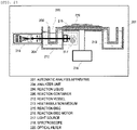
- Fig. 1 is a diagrammatic view of the construction of one embodiment of the automatic analysis apparatus of the invention.
- the automatic analysis apparatus is constructed mainly from a traveling line (101), a reaction disc (104), a reagent disc (103), and a spectroscope (107) .
- a biological sample rack (111) on which biological sample containers (110) are laid is moved from the traveling line (101) to a rotor (102), and moved to a shield portion (114) which is the position for injection. Then, a biological sample necessary for the analysis is injected by an injection mechanism (105) into a reaction container (112) on the reaction disc (104) . Further, a required reagent is injected from a reagent container (113) on the reagent disc (103) into the reaction container (112), and the resultant reaction liquid is mixed by a stirring mechanism (106).
- an absorbance is measured by the spectroscope (107). These mechanisms are controlled by a control unit (115). The measured absorbance is stored in a storage unit contained in the control unit (115).
- Fig. 2 is a detail view of the light intensity measurement in the automatic analysis apparatus of the invention.
- an analyzer unit (204) performs an analysis such that a light from a light source (217) is passed along an optical axis through a reaction liquid (206), which is formed by reacting a biological sample and a reagent in a reaction container (208) in the analyzer unit, to make a compositional analysis by a spectroscope (218).
- the reaction container (208) in the analyzer unit (204) is immersed in a heat insulation medium (213), such as water, stored in a reaction vessel (212), and maintained at a constant temperature.
- a heat insulation medium (213) such as water
- a plurality of the reaction containers (208) are disposed on a reaction disc (215), and rotated or moved together with the reaction disc (215) by controlling a reaction disc motor (216) by the control unit (115), so that the containers travel back and forth between the spectroscope (118) and the stirring mechanism (106) or the injection mechanism (105).
- Fig. 3 is an example of a block diagram of the light intensity measurement in the automatic analysis apparatus of the invention.
- the photometer is constructed from a spectroscope (302), a receptor element (303), a Log amplifier (304), and a light intensity signal processing unit (305).
- the light intensity signal processing unit (305) is constructed from an AD converter (307), a light quantity data storage unit (308), and a CPU or control unit (309).
- the amplified voltage signal is converted to a digital value, followed by data conversion in the CPU or control unit (309), to output an absorbance using two wavelengths among a plurality of wavelengths in a general analysis item.
- the voltage signal converted to a digital value is temporarily stored in the light quantity data storage unit (308) .
- Data for light quantity with respect to a colorless and transparent liquid, such as pure water, measured immediately after installing the apparatus in a place where the apparatus is used, or immediately after replacing the part whose lifetime has ended is also stored in the light quantity data storage unit.
- a data analysis is performed in the CPU (309) (hereinafter, referred to also as "control unit") based on the data temporarily stored, and the data is compared with the light quantity data previously measured with respect to a colorless and transparent liquid to specify a deteriorating part or calculate the degree of deterioration of a part for optical system.
- the information can be provided with a user by means of a display device, such as a display. Further, when the data analysis detects the fact that the duration of life of a part is close to the end, for example, when the degree of deterioration becomes a predetermined degree, an alarm or the like can be output from the apparatus to provide information so as to urge a user or a field engineer to replace or clean the part.
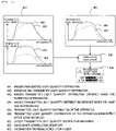
- Fig. 4 shows an example of the specification of a deteriorating part or the detection of deterioration of a part having a lifetime by a light quantity data analysis in the automatic analysis apparatus of the invention.
- a known transmitted light quantity distribution (401) is preliminarily stored in the light quantity data storage unit (308) in the apparatus. Further, as initial data at the time of the installation of the apparatus in a place where the apparatus is used or the replacement of a part, a transmitted light quantity distribution (406) of the apparatus immediately after being installed is also stored in the light quantity data storage unit (308) .
- the known transmitted light quantity distribution (403) obtained when the filter has deteriorated tends to be different from a known initial transmitted light quantity distribution (402) in respect of the properties of the reduction of the transmitted light quantity against the wavelengths.
- the known transmitted light quantity distribution (404) obtained when the lamp has deteriorated has a tendency that the properties of the reduction of the transmitted light quantity against the wavelengths are uniform irrespective of the wavelengths. For this reason, by analyzing the tendency of the reduction of the transmitted light from a transmitted light quantity distribution (407) measured in the latest measurement by the apparatus and the transmitted light quantity distribution (406) of the apparatus immediately after being installed, a part of the cause of deterioration can be specified and classified.
- a transmitted light quantity distribution (405) of the apparatus and the known transmitted light quantity distribution (401) by making an analysis using a wave-shape correlation operator (408), information about the specification of the deteriorating part or the degree of lifetime as information of the parts having a lifetime can be provided on an information providing screen (409) for a user.
- a user can grasp in advance the degree of preparation for the parts having a lifetime.
- the control unit calculates a correlation between the distributions, and the control unit can output the degree of deterioration of each of the parts based on the transmitted light distribution at the time of measurement and the calculated correlation.
- the parts are parts disposed on an optical axis of the light source, and an optical filter, a lamp, the below-described reaction container containing therein a substance to be measured, and a heat insulation medium for keeping the reaction container warm can be applied to the parts, and a combination of other parts and a combination of the above parts can also be applied to the parts.
- Fig. 5 shows an example of calculation algorithm for the correlation and deterioration degree in the automatic analysis apparatus of the invention.
- the apparatus As a database (501) which has been preliminarily experimentally determined and stored, the apparatus has an initial transmitted light distribution, transmitted light distributions obtained respectively when the optical filter and lamp have deteriorated, and each transmitted light distribution at the limit in which the replacement is recommended by the manufacturer.
- the individual automatic analysis apparatus has a current transmitted light distribution as a real-time acquired data (502).
- Fig. 6 shows an example of a phenomenon in which detection of other malfunctions can be expected in the automatic analysis apparatus of the invention.
- the deterioration of a reaction container (601) and pollution of a heat insulation medium (607) can be expected to be detected.
- a transmitted light quantity distribution (606) of a reaction container (b) having a flaw is likely to be lowered in the transmitted light quantity, as compared to a transmitted light quantity distribution (605) of a reaction container (a) having no flaw.
- a transmitted light quantity distribution (605) of a reaction container (a) having no flaw In the deterioration of a lamp or a filter described above with reference to Fig. 4 , with respect to the transmitted light quantity distribution for the light which has passed through all the reaction containers passing an optical axis (602) of the lamp, similar properties of the reduction of the transmitted light quantity are exhibited.
- a transmitted light quantity distribution (608) of a reaction container (e) and a transmitted light quantity distribution (609) of an adjacent reaction container (f) exhibit similar properties of the reduction of the light quantity, as compared to an initial transmitted light quantity distribution (604), and therefore can be distinguished from the above-mentioned detection of a malfunction of the individual reaction containers.
- the deteriorating part can be specified or the degree of deterioration can be output.
- Fig. 7 shows an example of the data acquisition timing in the automatic analysis apparatus of the invention.
- a basic data acquisition in a series of apparatuses (701) acquires data in order to establish a database for the parts which are normal and malfunction as general properties of a series of apparatuses.
- An instantaneous data acquisition in each apparatus (702) is a data acquisition for checking the current degree of lifetime or whether a malfunction occurs or not.
- a data acquisition after the condition renewal in each apparatus (703) acquires a transmitted light distribution characteristic of the apparatus, and, after completion of the installation of the apparatus, data to be stored as an initial transmitted light quantity distribution of the apparatus is acquired. Further, also when the condition of the apparatus is changed by replacement of the part whose lifetime has ended, or the like, data is acquired, and the stored initial transmitted light distribution data is replaced by the acquired data.
Landscapes
- Physics & Mathematics (AREA)
- Spectroscopy & Molecular Physics (AREA)
- General Physics & Mathematics (AREA)
- Immunology (AREA)
- Chemical & Material Sciences (AREA)
- Analytical Chemistry (AREA)
- Biochemistry (AREA)
- General Health & Medical Sciences (AREA)
- Health & Medical Sciences (AREA)
- Life Sciences & Earth Sciences (AREA)
- Pathology (AREA)
- Engineering & Computer Science (AREA)
- Quality & Reliability (AREA)
- Mathematical Physics (AREA)
- Theoretical Computer Science (AREA)
- Investigating Or Analysing Materials By Optical Means (AREA)
- Automatic Analysis And Handling Materials Therefor (AREA)
- Investigating Or Analysing Materials By The Use Of Chemical Reactions (AREA)
Claims (6)
- Automatisches Analysegerät, umfassend:eine Lichtquelle (217) zum Aussenden von Licht entlang einer optischen Achse (602) in Richtung einer zu messenden Substanz (206);ein Empfängerelement (303) zum Erfassen einer Durchlichtmengenverteilung für eine Vielzahl von Wellenlängen beim Messen von Durchlicht, das von der Lichtquelle durch die zu messende Substanz hindurchgegangen ist;eine Datenspeichereinheit (308) zum Speichern einer aktuellen Durchlichtmengenverteilung (407) für die Vielzahl von Wellenlängen, die von dem Empfängerelement (303) erfasst werden, und zum vorläufigen Speichern bekannter Durchlichtmengenverteilungen (401) für die Vielzahl von Wellenlängen, wobei die Verteilungen Eigenschaften der Verringerung der Durchlichtmenge abhängig von der Vielzahl von Wellenlängen aufgrund von Verschlechterung zeigen, undeine Steuereinheit (309) zum Vergleichen der bekannten, in der Datenspeichereinheit (308) vorläufig gespeicherten Durchlichtmengenverteilungen (401) mit der zum Zeitpunkt der Messung erfassten aktuellen Durchlichtmengenverteilung (407),dadurch gekennzeichnet, dass die bekanntenDurchlichtmengenverteilungen (401) für jeden von mindestens zwei Bestandteilen des automatischen Analysegeräts eine anfängliche Durchlichtmengenverteilung (402) für die Mehrzahl von Wellenlängen und eine experimentell bestimmte Durchlichtmengenverteilung (403, 404) für die Mehrzahl von Wellenlängen, wenn sich das Bauteil verschlechtert hat, undferner eine unmittelbar nach der Installation der automatischen Analysevorrichtung an einem Ort, an dem sie verwendet werden soll,gemessene Durchlichtmengenverteilung (406) umfassen, wobei die mindestens zwei Bauteile die Lichtquelle (217) und ein oder mehrere auf der optischen Achse angeordnete Bauteile umfassen;wobei die Steuereinheit (309) dazu ausgelegt ist, eine Korrelation aus der aktuellen Durchlichtmengenverteilung und den bekannten Durchlichtmengenverteilungen unter Verwendung eines Wellenformkorrelationsoperators (408) zu berechnen und auf der Grundlage des Ergebnisses der Korrelationsberechnung einen Grad der Verschlechterung jedes der mindestens zwei Komponententeile zu berechnen.
- Automatisches Analysegerät nach Anspruch 1, wobei die mindestens zwei Komponententeile eine Kombination aus der Lichtquelle (217) und einem optischen Filter (220), der auf der optischen Achse angeordnet ist, oder eine Kombination aus einem Reaktionsbehälter (208), der die zu messende Substanz enthält, und einem Wärmeisolationsmedium (213) zum Warmhalten des Reaktionsbehälters (208) umfassen.
- Automatisches Analysegerät nach Anspruch 1, wobei die Lichtquelle (217) eine Lampe umfasst, und wobei die mindestens zwei Komponententeile mindestens einen optischen Filter (220) und die Lampe umfassen.
- Automatisches Analysegerät nach Anspruch 3, wobei die mindestens zwei Komponententeile einen Reaktionsbehälter (208), der die zu messende Substanz enthält, und ein Wärmeisoliermedium (213) zum Warmhalten des Reaktionsbehälters (208) umfassen.
- Automatisches Analysegerät nach Anspruch 1, ferner mit einer Anzeigevorrichtung (409) zur Darstellung von Informationen,
wobei die Steuereinheit (309) dazu eingerichtet ist, den Grad der Bestimmung jedes der mindestens zwei Komponententeile an die Anzeigevorrichtung (409) auszugeben. - Automatisches Analysegerät nach Anspruch 5, wobei die Anzeigevorrichtung (409) so ausgebildet ist, dass sie einen Alarm anzeigt, wenn der Grad der Verschlechterung einen vorbestimmten Grad erreicht.
Applications Claiming Priority (2)
| Application Number | Priority Date | Filing Date | Title |
|---|---|---|---|
| JP2013016321A JP6129568B2 (ja) | 2013-01-31 | 2013-01-31 | 自動分析装置 |
| PCT/JP2014/051172 WO2014119435A1 (ja) | 2013-01-31 | 2014-01-22 | 自動分析装置 |
Publications (3)
| Publication Number | Publication Date |
|---|---|
| EP2952879A1 EP2952879A1 (de) | 2015-12-09 |
| EP2952879A4 EP2952879A4 (de) | 2016-10-26 |
| EP2952879B1 true EP2952879B1 (de) | 2022-10-12 |
Family
ID=51262149
Family Applications (1)
| Application Number | Title | Priority Date | Filing Date |
|---|---|---|---|
| EP14746842.5A Active EP2952879B1 (de) | 2013-01-31 | 2014-01-22 | Automatischer analysator |
Country Status (5)
| Country | Link |
|---|---|
| US (1) | US9575083B2 (de) |
| EP (1) | EP2952879B1 (de) |
| JP (1) | JP6129568B2 (de) |
| CN (1) | CN104937393B (de) |
| WO (1) | WO2014119435A1 (de) |
Families Citing this family (6)
| Publication number | Priority date | Publication date | Assignee | Title |
|---|---|---|---|---|
| JP6658091B2 (ja) * | 2016-02-29 | 2020-03-04 | 株式会社島津製作所 | 分析測定装置システム |
| US11953475B2 (en) * | 2018-04-16 | 2024-04-09 | Shimadzu Corporation | Absorbance detector and liquid chromatograph |
| WO2020148842A1 (ja) * | 2019-01-16 | 2020-07-23 | 株式会社島津製作所 | 吸光度検出器、クロマトグラフおよび光源交換時期管理方法 |
| WO2022026844A1 (en) | 2020-07-31 | 2022-02-03 | Ecolab Usa Inc. | Large dynamic range kinetic monitor |
| CN115541897B (zh) * | 2021-06-30 | 2025-05-02 | 深圳市帝迈生物技术有限公司 | 血液分析仪预警方法和血液分析仪 |
| CN114858757B (zh) * | 2022-04-08 | 2025-10-24 | 深圳市科曼医疗设备有限公司 | 数据采集与上传方法、设备和介质 |
Family Cites Families (15)
| Publication number | Priority date | Publication date | Assignee | Title |
|---|---|---|---|---|
| JPS64451A (en) * | 1987-02-20 | 1989-01-05 | Nittec Co Ltd | Method and instrument for optical measurement with automatic analysis device |
| JPH04204253A (ja) * | 1990-11-30 | 1992-07-24 | Hitachi Cable Ltd | 電線・ケーブルの劣化診断法 |
| JP3242500B2 (ja) * | 1993-09-07 | 2001-12-25 | 東亜ディーケーケー株式会社 | 吸光光度計の自己診断方法 |
| JP3860846B2 (ja) * | 1994-02-25 | 2006-12-20 | 株式会社日立製作所 | 材料の劣化度測定システムおよび測定装置 |
| JPH09222393A (ja) * | 1996-02-16 | 1997-08-26 | Hitachi Ltd | 劣化度診断装置 |
| JPH09229939A (ja) | 1996-02-22 | 1997-09-05 | Hitachi Ltd | 自動化学分析装置における測光系の精度確認方法 |
| TW343281B (en) * | 1996-06-28 | 1998-10-21 | Hitachi Ltd | Method and apparatus for diagnosing degradation of an electric machine |
| JPH11342123A (ja) * | 1998-06-03 | 1999-12-14 | Omron Corp | 非侵襲生体成分測定装置 |
| JP2004251802A (ja) * | 2003-02-21 | 2004-09-09 | Toshiba Corp | 自動分析装置 |
| JP2009047545A (ja) * | 2007-08-20 | 2009-03-05 | Olympus Corp | 分析装置および光源劣化検出方法 |
| JP4654256B2 (ja) * | 2008-02-28 | 2011-03-16 | 株式会社日立ハイテクノロジーズ | 自動分析装置 |
| JP5124498B2 (ja) * | 2009-01-30 | 2013-01-23 | 株式会社日立ハイテクノロジーズ | 自動分析装置 |
| JP5271776B2 (ja) * | 2009-04-02 | 2013-08-21 | 株式会社日立ハイテクノロジーズ | 自動分析装置 |
| JP5667757B2 (ja) * | 2009-11-04 | 2015-02-12 | トヨタホーム株式会社 | 建物外観の劣化診断方法及び建物外観の劣化診断システム |
| JP5373573B2 (ja) | 2009-12-01 | 2013-12-18 | 株式会社日立ハイテクノロジーズ | 自動分析装置、および自動分析装置の光源ランプ交換方法 |
-
2013
- 2013-01-31 JP JP2013016321A patent/JP6129568B2/ja active Active
-
2014
- 2014-01-22 US US14/762,922 patent/US9575083B2/en active Active
- 2014-01-22 WO PCT/JP2014/051172 patent/WO2014119435A1/ja not_active Ceased
- 2014-01-22 CN CN201480005796.8A patent/CN104937393B/zh active Active
- 2014-01-22 EP EP14746842.5A patent/EP2952879B1/de active Active
Also Published As
| Publication number | Publication date |
|---|---|
| EP2952879A1 (de) | 2015-12-09 |
| US9575083B2 (en) | 2017-02-21 |
| CN104937393B (zh) | 2018-01-02 |
| JP6129568B2 (ja) | 2017-05-17 |
| WO2014119435A1 (ja) | 2014-08-07 |
| JP2014149155A (ja) | 2014-08-21 |
| CN104937393A (zh) | 2015-09-23 |
| EP2952879A4 (de) | 2016-10-26 |
| US20150369831A1 (en) | 2015-12-24 |
Similar Documents
| Publication | Publication Date | Title |
|---|---|---|
| EP2952879B1 (de) | Automatischer analysator | |
| JP4654256B2 (ja) | 自動分析装置 | |
| US9476893B2 (en) | Automatic analysis device and analysis method | |
| EP1840559B1 (de) | Blutanalysegerät und Blutanalyseverfahren | |
| US20120282137A1 (en) | Automatic analyzer | |
| JP6368067B2 (ja) | 質量分析装置及び質量分析方法 | |
| JP2009180616A (ja) | 自動分析装置 | |
| EP3535578B1 (de) | Überwachung der komponenten eines gasanalysators | |
| JPH04130248A (ja) | 自動分析装置 | |
| JP2000105239A (ja) | 生化学自動分析装置 | |
| JP5271776B2 (ja) | 自動分析装置 | |
| JP6658091B2 (ja) | 分析測定装置システム | |
| EP3514548B1 (de) | Automatische analysevorrichtung | |
| JP2007248090A (ja) | 臨床検査の精度管理システム | |
| JP7643971B2 (ja) | 化学分析装置 | |
| EP3290905B1 (de) | Signal-offset-bestimmung und korrektur | |
| CN117554303A (zh) | 液体检测方法、装置、设备及存储介质 | |
| JPS60161546A (ja) | 気泡検知装置 | |
| US20260009810A1 (en) | Real-time cuvette monitoring | |
| WO2024237046A1 (ja) | 自動分析装置およびタイミング設定方法 | |
| WO2024195510A1 (ja) | 自動分析装置及び検体分析方法 | |
| JPH09101312A (ja) | 自動分析装置および反応容器 | |
| JPH04105047A (ja) | 異性化終了判定方法 | |
| JP2006162355A (ja) | 装置組込み型光度計の波長確認方法及び自動分析装置 | |
| Schneider et al. | Quality Assessment of Spectroscopic Methods in Clinical Laboratories |
Legal Events
| Date | Code | Title | Description |
|---|---|---|---|
| PUAI | Public reference made under article 153(3) epc to a published international application that has entered the european phase |
Free format text: ORIGINAL CODE: 0009012 |
|
| 17P | Request for examination filed |
Effective date: 20150820 |
|
| AK | Designated contracting states |
Kind code of ref document: A1 Designated state(s): AL AT BE BG CH CY CZ DE DK EE ES FI FR GB GR HR HU IE IS IT LI LT LU LV MC MK MT NL NO PL PT RO RS SE SI SK SM TR |
|
| AX | Request for extension of the european patent |
Extension state: BA ME |
|
| DAX | Request for extension of the european patent (deleted) | ||
| A4 | Supplementary search report drawn up and despatched |
Effective date: 20160923 |
|
| RIC1 | Information provided on ipc code assigned before grant |
Ipc: G01N 35/00 20060101ALI20160919BHEP Ipc: G01N 21/03 20060101ALN20160919BHEP Ipc: G01N 35/02 20060101ALI20160919BHEP Ipc: G01N 21/27 20060101ALI20160919BHEP Ipc: G01N 21/31 20060101ALI20160919BHEP Ipc: G01N 21/25 20060101AFI20160919BHEP |
|
| STAA | Information on the status of an ep patent application or granted ep patent |
Free format text: STATUS: EXAMINATION IS IN PROGRESS |
|
| 17Q | First examination report despatched |
Effective date: 20200403 |
|
| RAP1 | Party data changed (applicant data changed or rights of an application transferred) |
Owner name: HITACHI HIGH-TECH CORPORATION |
|
| REG | Reference to a national code |
Ref country code: DE Ref legal event code: R079 Ref document number: 602014085206 Country of ref document: DE Free format text: PREVIOUS MAIN CLASS: G01N0021270000 Ipc: G01N0021250000 |
|
| RIC1 | Information provided on ipc code assigned before grant |
Ipc: G01N 35/02 20060101ALN20220329BHEP Ipc: G01N 21/03 20060101ALN20220329BHEP Ipc: G01N 35/00 20060101ALI20220329BHEP Ipc: G01N 21/31 20060101ALI20220329BHEP Ipc: G01N 21/27 20060101ALI20220329BHEP Ipc: G01N 21/25 20060101AFI20220329BHEP |
|
| GRAP | Despatch of communication of intention to grant a patent |
Free format text: ORIGINAL CODE: EPIDOSNIGR1 |
|
| STAA | Information on the status of an ep patent application or granted ep patent |
Free format text: STATUS: GRANT OF PATENT IS INTENDED |
|
| INTG | Intention to grant announced |
Effective date: 20220516 |
|
| GRAS | Grant fee paid |
Free format text: ORIGINAL CODE: EPIDOSNIGR3 |
|
| GRAA | (expected) grant |
Free format text: ORIGINAL CODE: 0009210 |
|
| STAA | Information on the status of an ep patent application or granted ep patent |
Free format text: STATUS: THE PATENT HAS BEEN GRANTED |
|
| AK | Designated contracting states |
Kind code of ref document: B1 Designated state(s): AL AT BE BG CH CY CZ DE DK EE ES FI FR GB GR HR HU IE IS IT LI LT LU LV MC MK MT NL NO PL PT RO RS SE SI SK SM TR |
|
| REG | Reference to a national code |
Ref country code: GB Ref legal event code: FG4D |
|
| RIN1 | Information on inventor provided before grant (corrected) |
Inventor name: NISHIGAKI, KENICHI |
|
| REG | Reference to a national code |
Ref country code: CH Ref legal event code: EP |
|
| REG | Reference to a national code |
Ref country code: DE Ref legal event code: R096 Ref document number: 602014085206 Country of ref document: DE |
|
| REG | Reference to a national code |
Ref country code: IE Ref legal event code: FG4D |
|
| REG | Reference to a national code |
Ref country code: AT Ref legal event code: REF Ref document number: 1524445 Country of ref document: AT Kind code of ref document: T Effective date: 20221115 |
|
| REG | Reference to a national code |
Ref country code: LT Ref legal event code: MG9D |
|
| REG | Reference to a national code |
Ref country code: NL Ref legal event code: MP Effective date: 20221012 |
|
| REG | Reference to a national code |
Ref country code: AT Ref legal event code: MK05 Ref document number: 1524445 Country of ref document: AT Kind code of ref document: T Effective date: 20221012 |
|
| PG25 | Lapsed in a contracting state [announced via postgrant information from national office to epo] |
Ref country code: NL Free format text: LAPSE BECAUSE OF FAILURE TO SUBMIT A TRANSLATION OF THE DESCRIPTION OR TO PAY THE FEE WITHIN THE PRESCRIBED TIME-LIMIT Effective date: 20221012 |
|
| PG25 | Lapsed in a contracting state [announced via postgrant information from national office to epo] |
Ref country code: SE Free format text: LAPSE BECAUSE OF FAILURE TO SUBMIT A TRANSLATION OF THE DESCRIPTION OR TO PAY THE FEE WITHIN THE PRESCRIBED TIME-LIMIT Effective date: 20221012 Ref country code: PT Free format text: LAPSE BECAUSE OF FAILURE TO SUBMIT A TRANSLATION OF THE DESCRIPTION OR TO PAY THE FEE WITHIN THE PRESCRIBED TIME-LIMIT Effective date: 20230213 Ref country code: NO Free format text: LAPSE BECAUSE OF FAILURE TO SUBMIT A TRANSLATION OF THE DESCRIPTION OR TO PAY THE FEE WITHIN THE PRESCRIBED TIME-LIMIT Effective date: 20230112 Ref country code: LT Free format text: LAPSE BECAUSE OF FAILURE TO SUBMIT A TRANSLATION OF THE DESCRIPTION OR TO PAY THE FEE WITHIN THE PRESCRIBED TIME-LIMIT Effective date: 20221012 Ref country code: FI Free format text: LAPSE BECAUSE OF FAILURE TO SUBMIT A TRANSLATION OF THE DESCRIPTION OR TO PAY THE FEE WITHIN THE PRESCRIBED TIME-LIMIT Effective date: 20221012 Ref country code: ES Free format text: LAPSE BECAUSE OF FAILURE TO SUBMIT A TRANSLATION OF THE DESCRIPTION OR TO PAY THE FEE WITHIN THE PRESCRIBED TIME-LIMIT Effective date: 20221012 Ref country code: AT Free format text: LAPSE BECAUSE OF FAILURE TO SUBMIT A TRANSLATION OF THE DESCRIPTION OR TO PAY THE FEE WITHIN THE PRESCRIBED TIME-LIMIT Effective date: 20221012 |
|
| PG25 | Lapsed in a contracting state [announced via postgrant information from national office to epo] |
Ref country code: RS Free format text: LAPSE BECAUSE OF FAILURE TO SUBMIT A TRANSLATION OF THE DESCRIPTION OR TO PAY THE FEE WITHIN THE PRESCRIBED TIME-LIMIT Effective date: 20221012 Ref country code: PL Free format text: LAPSE BECAUSE OF FAILURE TO SUBMIT A TRANSLATION OF THE DESCRIPTION OR TO PAY THE FEE WITHIN THE PRESCRIBED TIME-LIMIT Effective date: 20221012 Ref country code: LV Free format text: LAPSE BECAUSE OF FAILURE TO SUBMIT A TRANSLATION OF THE DESCRIPTION OR TO PAY THE FEE WITHIN THE PRESCRIBED TIME-LIMIT Effective date: 20221012 Ref country code: IS Free format text: LAPSE BECAUSE OF FAILURE TO SUBMIT A TRANSLATION OF THE DESCRIPTION OR TO PAY THE FEE WITHIN THE PRESCRIBED TIME-LIMIT Effective date: 20230212 Ref country code: HR Free format text: LAPSE BECAUSE OF FAILURE TO SUBMIT A TRANSLATION OF THE DESCRIPTION OR TO PAY THE FEE WITHIN THE PRESCRIBED TIME-LIMIT Effective date: 20221012 Ref country code: GR Free format text: LAPSE BECAUSE OF FAILURE TO SUBMIT A TRANSLATION OF THE DESCRIPTION OR TO PAY THE FEE WITHIN THE PRESCRIBED TIME-LIMIT Effective date: 20230113 |
|
| REG | Reference to a national code |
Ref country code: DE Ref legal event code: R097 Ref document number: 602014085206 Country of ref document: DE |
|
| PG25 | Lapsed in a contracting state [announced via postgrant information from national office to epo] |
Ref country code: SM Free format text: LAPSE BECAUSE OF FAILURE TO SUBMIT A TRANSLATION OF THE DESCRIPTION OR TO PAY THE FEE WITHIN THE PRESCRIBED TIME-LIMIT Effective date: 20221012 Ref country code: RO Free format text: LAPSE BECAUSE OF FAILURE TO SUBMIT A TRANSLATION OF THE DESCRIPTION OR TO PAY THE FEE WITHIN THE PRESCRIBED TIME-LIMIT Effective date: 20221012 Ref country code: EE Free format text: LAPSE BECAUSE OF FAILURE TO SUBMIT A TRANSLATION OF THE DESCRIPTION OR TO PAY THE FEE WITHIN THE PRESCRIBED TIME-LIMIT Effective date: 20221012 Ref country code: DK Free format text: LAPSE BECAUSE OF FAILURE TO SUBMIT A TRANSLATION OF THE DESCRIPTION OR TO PAY THE FEE WITHIN THE PRESCRIBED TIME-LIMIT Effective date: 20221012 Ref country code: CZ Free format text: LAPSE BECAUSE OF FAILURE TO SUBMIT A TRANSLATION OF THE DESCRIPTION OR TO PAY THE FEE WITHIN THE PRESCRIBED TIME-LIMIT Effective date: 20221012 |
|
| PLBE | No opposition filed within time limit |
Free format text: ORIGINAL CODE: 0009261 |
|
| STAA | Information on the status of an ep patent application or granted ep patent |
Free format text: STATUS: NO OPPOSITION FILED WITHIN TIME LIMIT |
|
| PG25 | Lapsed in a contracting state [announced via postgrant information from national office to epo] |
Ref country code: SK Free format text: LAPSE BECAUSE OF FAILURE TO SUBMIT A TRANSLATION OF THE DESCRIPTION OR TO PAY THE FEE WITHIN THE PRESCRIBED TIME-LIMIT Effective date: 20221012 Ref country code: AL Free format text: LAPSE BECAUSE OF FAILURE TO SUBMIT A TRANSLATION OF THE DESCRIPTION OR TO PAY THE FEE WITHIN THE PRESCRIBED TIME-LIMIT Effective date: 20221012 |
|
| REG | Reference to a national code |
Ref country code: CH Ref legal event code: PL |
|
| 26N | No opposition filed |
Effective date: 20230713 |
|
| GBPC | Gb: european patent ceased through non-payment of renewal fee |
Effective date: 20230122 |
|
| PG25 | Lapsed in a contracting state [announced via postgrant information from national office to epo] |
Ref country code: LU Free format text: LAPSE BECAUSE OF NON-PAYMENT OF DUE FEES Effective date: 20230122 |
|
| REG | Reference to a national code |
Ref country code: BE Ref legal event code: MM Effective date: 20230131 |
|
| PG25 | Lapsed in a contracting state [announced via postgrant information from national office to epo] |
Ref country code: LI Free format text: LAPSE BECAUSE OF NON-PAYMENT OF DUE FEES Effective date: 20230131 Ref country code: GB Free format text: LAPSE BECAUSE OF NON-PAYMENT OF DUE FEES Effective date: 20230122 Ref country code: CH Free format text: LAPSE BECAUSE OF NON-PAYMENT OF DUE FEES Effective date: 20230131 |
|
| PG25 | Lapsed in a contracting state [announced via postgrant information from national office to epo] |
Ref country code: SI Free format text: LAPSE BECAUSE OF FAILURE TO SUBMIT A TRANSLATION OF THE DESCRIPTION OR TO PAY THE FEE WITHIN THE PRESCRIBED TIME-LIMIT Effective date: 20221012 Ref country code: BE Free format text: LAPSE BECAUSE OF NON-PAYMENT OF DUE FEES Effective date: 20230131 |
|
| PG25 | Lapsed in a contracting state [announced via postgrant information from national office to epo] |
Ref country code: IE Free format text: LAPSE BECAUSE OF NON-PAYMENT OF DUE FEES Effective date: 20230122 |
|
| PG25 | Lapsed in a contracting state [announced via postgrant information from national office to epo] |
Ref country code: IT Free format text: LAPSE BECAUSE OF FAILURE TO SUBMIT A TRANSLATION OF THE DESCRIPTION OR TO PAY THE FEE WITHIN THE PRESCRIBED TIME-LIMIT Effective date: 20221012 |
|
| PG25 | Lapsed in a contracting state [announced via postgrant information from national office to epo] |
Ref country code: MC Free format text: LAPSE BECAUSE OF FAILURE TO SUBMIT A TRANSLATION OF THE DESCRIPTION OR TO PAY THE FEE WITHIN THE PRESCRIBED TIME-LIMIT Effective date: 20221012 |
|
| PG25 | Lapsed in a contracting state [announced via postgrant information from national office to epo] |
Ref country code: MC Free format text: LAPSE BECAUSE OF FAILURE TO SUBMIT A TRANSLATION OF THE DESCRIPTION OR TO PAY THE FEE WITHIN THE PRESCRIBED TIME-LIMIT Effective date: 20221012 |
|
| PG25 | Lapsed in a contracting state [announced via postgrant information from national office to epo] |
Ref country code: BG Free format text: LAPSE BECAUSE OF FAILURE TO SUBMIT A TRANSLATION OF THE DESCRIPTION OR TO PAY THE FEE WITHIN THE PRESCRIBED TIME-LIMIT Effective date: 20221012 |
|
| PG25 | Lapsed in a contracting state [announced via postgrant information from national office to epo] |
Ref country code: BG Free format text: LAPSE BECAUSE OF FAILURE TO SUBMIT A TRANSLATION OF THE DESCRIPTION OR TO PAY THE FEE WITHIN THE PRESCRIBED TIME-LIMIT Effective date: 20221012 |
|
| PGFP | Annual fee paid to national office [announced via postgrant information from national office to epo] |
Ref country code: DE Payment date: 20241203 Year of fee payment: 12 |
|
| PG25 | Lapsed in a contracting state [announced via postgrant information from national office to epo] |
Ref country code: CY Free format text: LAPSE BECAUSE OF FAILURE TO SUBMIT A TRANSLATION OF THE DESCRIPTION OR TO PAY THE FEE WITHIN THE PRESCRIBED TIME-LIMIT; INVALID AB INITIO Effective date: 20140122 |
|
| PG25 | Lapsed in a contracting state [announced via postgrant information from national office to epo] |
Ref country code: HU Free format text: LAPSE BECAUSE OF FAILURE TO SUBMIT A TRANSLATION OF THE DESCRIPTION OR TO PAY THE FEE WITHIN THE PRESCRIBED TIME-LIMIT; INVALID AB INITIO Effective date: 20140122 |
|
| PG25 | Lapsed in a contracting state [announced via postgrant information from national office to epo] |
Ref country code: TR Free format text: LAPSE BECAUSE OF FAILURE TO SUBMIT A TRANSLATION OF THE DESCRIPTION OR TO PAY THE FEE WITHIN THE PRESCRIBED TIME-LIMIT Effective date: 20221012 |
|
| PGFP | Annual fee paid to national office [announced via postgrant information from national office to epo] |
Ref country code: FR Payment date: 20251217 Year of fee payment: 13 |