EP2952419B1 - Feder-dämpferelement für die kabinenfederung von fahrzeugen - Google Patents
Feder-dämpferelement für die kabinenfederung von fahrzeugen Download PDFInfo
- Publication number
- EP2952419B1 EP2952419B1 EP15001287.0A EP15001287A EP2952419B1 EP 2952419 B1 EP2952419 B1 EP 2952419B1 EP 15001287 A EP15001287 A EP 15001287A EP 2952419 B1 EP2952419 B1 EP 2952419B1
- Authority
- EP
- European Patent Office
- Prior art keywords
- suspension cylinder
- spring element
- suspension
- element according
- damping valve
- Prior art date
- Legal status (The legal status is an assumption and is not a legal conclusion. Google has not performed a legal analysis and makes no representation as to the accuracy of the status listed.)
- Active
Links
- 239000000725 suspension Substances 0.000 title claims description 45
- 238000013016 damping Methods 0.000 claims description 29
- 239000012530 fluid Substances 0.000 claims description 15
- 239000003921 oil Substances 0.000 claims description 8
- 238000004891 communication Methods 0.000 claims description 4
- 239000010720 hydraulic oil Substances 0.000 claims description 3
- 238000006073 displacement reaction Methods 0.000 claims description 2
- 230000001419 dependent effect Effects 0.000 description 3
- 238000009434 installation Methods 0.000 description 3
- 238000007789 sealing Methods 0.000 description 3
- 240000006829 Ficus sundaica Species 0.000 description 2
- 230000003044 adaptive effect Effects 0.000 description 2
- 238000010276 construction Methods 0.000 description 2
- 230000006641 stabilisation Effects 0.000 description 2
- 238000011105 stabilization Methods 0.000 description 2
- 230000001133 acceleration Effects 0.000 description 1
- 230000007423 decrease Effects 0.000 description 1
- RZTAMFZIAATZDJ-UHFFFAOYSA-N felodipine Chemical compound CCOC(=O)C1=C(C)NC(C)=C(C(=O)OC)C1C1=CC=CC(Cl)=C1Cl RZTAMFZIAATZDJ-UHFFFAOYSA-N 0.000 description 1
- 238000000034 method Methods 0.000 description 1
- 230000001681 protective effect Effects 0.000 description 1
- 230000003014 reinforcing effect Effects 0.000 description 1
- 230000035939 shock Effects 0.000 description 1
- 230000008054 signal transmission Effects 0.000 description 1
Images

Classifications
-
- B—PERFORMING OPERATIONS; TRANSPORTING
- B62—LAND VEHICLES FOR TRAVELLING OTHERWISE THAN ON RAILS
- B62D—MOTOR VEHICLES; TRAILERS
- B62D33/00—Superstructures for load-carrying vehicles
- B62D33/06—Drivers' cabs
- B62D33/0604—Cabs insulated against vibrations or noise, e.g. with elastic suspension
- B62D33/0608—Cabs insulated against vibrations or noise, e.g. with elastic suspension pneumatic or hydraulic suspension
-
- B—PERFORMING OPERATIONS; TRANSPORTING
- B60—VEHICLES IN GENERAL
- B60G—VEHICLE SUSPENSION ARRANGEMENTS
- B60G17/00—Resilient suspensions having means for adjusting the spring or vibration-damper characteristics, for regulating the distance between a supporting surface and a sprung part of vehicle or for locking suspension during use to meet varying vehicular or surface conditions, e.g. due to speed or load
- B60G17/02—Spring characteristics, e.g. mechanical springs and mechanical adjusting means
- B60G17/04—Spring characteristics, e.g. mechanical springs and mechanical adjusting means fluid spring characteristics
-
- B—PERFORMING OPERATIONS; TRANSPORTING
- B60—VEHICLES IN GENERAL
- B60G—VEHICLE SUSPENSION ARRANGEMENTS
- B60G17/00—Resilient suspensions having means for adjusting the spring or vibration-damper characteristics, for regulating the distance between a supporting surface and a sprung part of vehicle or for locking suspension during use to meet varying vehicular or surface conditions, e.g. due to speed or load
- B60G17/06—Characteristics of dampers, e.g. mechanical dampers
- B60G17/08—Characteristics of fluid dampers
-
- B—PERFORMING OPERATIONS; TRANSPORTING
- B60—VEHICLES IN GENERAL
- B60G—VEHICLE SUSPENSION ARRANGEMENTS
- B60G99/00—Subject matter not provided for in other groups of this subclass
- B60G99/002—Suspension details of the suspension of the vehicle body on the vehicle chassis
-
- F—MECHANICAL ENGINEERING; LIGHTING; HEATING; WEAPONS; BLASTING
- F16—ENGINEERING ELEMENTS AND UNITS; GENERAL MEASURES FOR PRODUCING AND MAINTAINING EFFECTIVE FUNCTIONING OF MACHINES OR INSTALLATIONS; THERMAL INSULATION IN GENERAL
- F16F—SPRINGS; SHOCK-ABSORBERS; MEANS FOR DAMPING VIBRATION
- F16F9/00—Springs, vibration-dampers, shock-absorbers, or similarly-constructed movement-dampers using a fluid or the equivalent as damping medium
- F16F9/06—Springs, vibration-dampers, shock-absorbers, or similarly-constructed movement-dampers using a fluid or the equivalent as damping medium using both gas and liquid
- F16F9/08—Springs, vibration-dampers, shock-absorbers, or similarly-constructed movement-dampers using a fluid or the equivalent as damping medium using both gas and liquid where gas is in a chamber with a flexible wall
- F16F9/096—Springs, vibration-dampers, shock-absorbers, or similarly-constructed movement-dampers using a fluid or the equivalent as damping medium using both gas and liquid where gas is in a chamber with a flexible wall comprising a hydropneumatic accumulator of the membrane type provided on the upper or the lower end of a damper or separately from or laterally on the damper
-
- B—PERFORMING OPERATIONS; TRANSPORTING
- B60—VEHICLES IN GENERAL
- B60G—VEHICLE SUSPENSION ARRANGEMENTS
- B60G2204/00—Indexing codes related to suspensions per se or to auxiliary parts
- B60G2204/10—Mounting of suspension elements
- B60G2204/16—Mounting of vehicle body on chassis
- B60G2204/162—Cabins, e.g. for trucks, tractors
Definitions
- the invention relates to a spring element, in particular spring-damper element for the cabin suspension of vehicles, such as mobile machines, having the features in the preamble of claim 1.
- Spring elements of this type are prior art. Such spring elements with double-acting suspension cylinders are preferably used in cabin suspensions of vehicles, which are suitable for operation on rough unpaved ground, as is the case with agricultural or forestry vehicles, construction machinery or other special vehicles. In order to protect the cabin crew against shock loads occurring during operation, cabins of such vehicles are usually supported by double acting suspension cylinders relative to the chassis.
- a piping is provided between the working spaces to form a fluid connection, usually in the form of a pipeline extending along the outside of the suspension cylinder between the bottom part, where the articulation point for connection to the chassis, and the head part of the Suspension cylinder extends, from which the piston rod is led out and at the end of the pivot point for connection to a car part is located.
- the external connection formed by the pipeline is disadvantageous in that it contributes to the bulkiness of the overall structural unit the spring element contributes, which in the limited installation space, as is usually available in the eligible mobile work equipment, the installation complicated and difficult.
- an external piping poses a safety risk due to the risk of damage due to the action of external, mechanical forces.
- the WO 93/17254 A1 describes a generic spring element, with a suspension cylinder, at one end of a bottom part, which forms a bearing, is provided and in which a suspension piston whose piston rod is led out of the bottom part of the opposite head part of the suspension cylinder, working spaces for a pressurized fluid, such as hydraulic oil, separated, wherein the working chambers via a connecting line to each other in fluid communication, wherein the suspension cylinder is at least partially surrounded by a coaxial tubular body whose inner diameter is greater than the outer diameter of the suspension cylinder, so that between this and the tubular body, an outer space is formed, at least forms a section of the connecting line.
- a pressurized fluid such as hydraulic oil
- the invention has the object to provide a spring element of the type mentioned available, which is characterized by a particularly compact and reliable construction.
- a significant feature of the invention is that in the connecting line a variable throttle point forming, controllable damping valve is inserted, that the bottom part with a lateral approach forms a valve block for the damping valve and that the pressure accumulator directly to the Valve block is connected to form an internal connection to the damping valve.
- This embodiment of the invention in which a variable throttle point forming, controllable damping valve is inserted in the connecting line, can be used with particular advantage as a spring-damper element in adaptive suspension systems.
- the damping behavior can be adapted to the respective operating conditions in such a way that a reduced vibration load and an increase in engine and operator comfort are achieved Ride comfort are achieved.
- the suspension cylinder is at least partially surrounded by a coaxial tubular body whose inner diameter is greater than the outer diameter of the suspension cylinder, so that between this and the tubular body, an outer space is formed which forms at least a portion of the connecting line.
- inner fluid guide reduces the need for exposed to leading pipelines, so that the risk of compromising the reliability is reduced by external influences on an external piping.
- the arrangement is such that the tubular body surrounds the suspension cylinder in the form of an outer cylinder such that over the length of the suspension cylinder extending annular space is formed as a portion of the connecting line.
- an inner side portion of the connecting line forming annular space opens at the head end of the suspension cylinder in the rod-side working space and is at its bottom end located with the damping valve in connection.
- this can also be with its located at the bottom end with the damping valve in combination.
- the damping valve can be attached to the bottom part directly without external piping.
- At least one hydropneumatic pressure accumulator communicating with or communicable with the working spaces may be provided, so that the stiffness of the damping can be influenced as desired by the dimensioning of the accumulator.
- the associated with the workrooms oil side of the respective pressure accumulator can be connected to the hydraulic system of the relevant associated vehicle.
- supplying a corresponding system pressure can be realized via the spring element, a load-dependent level control.
- the spring element may form part of a roll stabilization system.
- a proportional 3/2-way valve can be provided. Further, as a safety device against a possible cavitation occurring in a working space may be provided between the oil side of the respective pressure accumulator and the rod side and the piston side working space per the one damper valve bypassing each containing a check valve in the direction of the respective working space to open. This ensures that, regardless of the control state of the damping valve, the pressure level of the working spaces corresponds to that of the pressure accumulator.
- a path measuring system recognizing the axial position of the piston rod in the suspension cylinder.
- Such a system which operates without contact, can correspond to the prior art and, for example, operate according to a magnetostrictive method in order to provide signals of the vehicle control indicative of the respective operating state of the spring element, for example for a load-dependent level control.
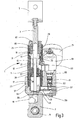
- the embodiment shown in the drawing is provided as an adaptive spring-damper element for use in a cabin suspension.
- the spring element designated as a whole by 1 has, as usual with such spring elements, a piston rod 3 which can be connected as a movable support element via a connecting part 5 to the structure of a driver's cab (not shown).
- a mounting part 7 is provided, on which (not shown) to form a bearing on the chassis of a respective vehicle a pivot point 9, see Fig. 3 , is formed.
- the piston rod 3 is formed as a hollow tube, so that a coaxially extending cavity 19 is formed for a distance measuring system 21, which will be discussed later.
- the suspension cylinder 13 forming the guide for the piston 11 extends along the spring travel provided for the piston 11 between a bottom part 23 located in the drawing and an upper end part 25.
- the suspension cylinder 13 is coaxially surrounded by a tubular body 27. which extends beyond the upper end of the suspension cylinder 13 and in the end portion an internal thread 29 (FIG. Fig. 3 ), in which the end part 25 is screwed in, wherein an O-ring 31 forms a seal on the tubular body 27.
- the end portion 25 forms at its inner end portion a support 33 for the suspension cylinder 13 to this on an inner bottom surface 35 (s. Fig. 2 ) of the bottom part 23.
- the bottom part 23 associated with the end of the tubular body 27 has an external thread 37, with which it is bolted to the bottom part 23, wherein an O-ring 38 forms the seal on the bottom part 23.
- the outer diameter of the suspension cylinder 13 is smaller than the inner diameter of a coaxial outer cylinder forming tubular body 27, so that along the outer side of the suspension cylinder 13 extending annular space 39 is formed.
- the end part 25 located at the upper end of the suspension cylinder 13 has an inwardly projecting sleeve part 41, which forms the support 33 on the suspension cylinder 13 and surrounds the piston rod 3 at a distance.
- the sleeve part 41 on radial openings 43, via which a fluid connection between the upper end of the annular space 39 and the rod-side working space 15 is formed.
- the bottom part 23 has, s. Fig. 2 and 3 , below the bottom surface 35 on a transverse channel 45, which is via passages 47 in the bottom surface 35 with the piston-side working space 17 in conjunction.
- a transverse channel 49 extending parallel to this above the transverse channel 45 is in fluid communication with the lower end 51 of the annular space 39.
- the bottom part 23 has a lateral projection 53, which forms the valve block for a damping valve 55. In operation, this creates between the transverse channels 45 and 47, which are closed by screw plugs 57 and a drain plug 59 to the outside, a fluid connection, which, depending on the valve position of the damping valve 55, more or less throttled.
- the annular space 39 therefore forms an internal connecting line for the fluid connection between the working spaces 15 and 17.
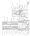
- the Fig. 2 shows the circuit of the damping valve 55 for the fluid communication between the transverse channels 45 and 49.
- the damping valve 55 is a proportional 3/2-way valve which is actuated electromagnetically by means of a magnetic coil 61, which can be excited via a plug device 63 is.
- the damping valve 55 communicates with its ports 65 and 67 with the transverse channel 49 and 45, respectively, and the third port 69 communicates with the oil side 70 of a hydropneumatic pressure accumulator 71.
- the oil side 70 is further connected via bypass lines 73 and 75, which bridge the damping valve 55, with the transverse channel 45 and the transverse channel 49, wherein in each bypass line 73, 75, a check valve 77 is inserted, each in the direction of the transverse channel 45th or 49 pressure-actuated open.
- the damping valve 55 has within the valve block formed by the projection 53 of the bottom part 23 throttle bodies, which, like the circuit of Fig. 2 can be removed, in the valve end position shown via one at each terminal 65 and 67 existing throttle body 79 connect the transverse channels 45 and 49, wherein the pressure accumulator 71 is also connected via the throttle bodies 79 with the transverse channels 45, 49 in connection.
- a connection 83 connected to the oil side 70 of the pressure accumulator 51 is provided for supplying the spring element 1 with the system pressure.
- Functional controls of the spring element 1 are possible via the connection 83 supplying P / T connections, such as load-dependent level control, roll stabilization or spring hardness, wherein the rigidity of the damping can be influenced by the dimensioning of the pressure accumulator 71.
- the check valves 77 avoid the risk of cavitation within the spring element 1 when a reduced pressure occurs during operation, by allowing a subsequent flow of fluid from the oil side 70 of the pressure accumulator 71.
- a vent hole 85 is provided with a vent screw 87 at the top of the rod-side working space 15 at the end part 25.
- damping valve 55 and pressure accumulator 71 are arranged in an inclined position to each other and the longitudinal axis, so that they, although they emanate from the valve body forming approach 53 together, to the outside of the Cling to outer cylinder forming tubular body 27.
- the inner cavity 19 of the piston rod 3 is provided for the engagement of a path-measuring system 21.
- the measuring system 21 projects in the form of a rod-like hollow body from the bottom of the bottom part 23 so far into the cavity 19, that the suspension piston 11 moves over the entire spring travel along the rod-like hollow body and within the measuring range formed by the measuring system 21.
- an opening 89 is provided in the bottom of the bottom part 23, which forms a sealed by a sealing element 93 seat for the rod-like body of the measuring system 21.
- a lateral access 91 is provided for an electrical connection and the signal transmission of the measuring system 21. How most obvious the Fig.
- FIG. 2 shows that the seat for the end of the measuring system 21 forming opening 89 in the bottom part 23 has a conically narrowing away from the working space 17 form.
- the end of the measuring system 21 is thereby pressed by the pressure in the working space 17 while reinforcing the effective sealing force on the sealing element 93 in the seat.
- a measuring system 21 may be provided a magnetostrictive linear displacement sensor series HLT 1100, as described by the company HYDAC Electronic GmbH, Hauptstr. 27, 66128 Saarmaschinen, Germany.
- the rod-like hollow body is a protective tube, in which a magnetostrictive waveguide is stretched.
- the piston 11 is provided with a permanent magnetic element forming the position sensor.
Description
- Die Erfindung betrifft ein Federelement, insbesondere Feder-Dämpfer-Element für die Kabinenfederung von Fahrzeugen, wie mobilen Arbeitsmaschinen, mit den Merkmalen im Oberbegriff von Anspruch 1.
- Federelemente dieser Art sind Stand der Technik. Derartige Federelemente mit doppelt wirkenden Federungszylindern kommen bevorzugt bei Kabinenfederungen von Fahrzeugen zum Einsatz, die für einen Betrieb auf rauem unbefestigtem Untergrund geeignet sind, wie dies bei landwirtschaftlichen oder forstwirtschaftlichen Fahrzeugen, Baumaschinen oder anderen Sonderfahrzeugen der Fall ist. Um das Kabinenpersonal gegen im Betrieb auftretende Stoßbelastungen zu schützen, sind Kabinen solcher Fahrzeuge üblicherweise über doppelt wirkende Federungszylinder gegenüber dem Fahrgestell abgestützt. Bei den bekannten Federelementen ist zur Bildung einer Fluidverbindung zwischen den Arbeitsräumen eine Verrohrung vorgesehen, üblicherweise in Form einer Rohrleitung, die sich entlang der Außenseite des Federungszylinders zwischen dessen Bodenteil, an dem sich die Anlenkstelle für die Verbindung mit dem Fahrgestell befindet, und dem Kopfteil des Federungszylinders erstreckt, aus dem die Kolbenstange herausgeführt ist und an deren Ende sich die Anlenkstelle für die Verbindung mit einem Kabinenteil befindet. Die durch die Rohrleitung gebildete externe Verbindung ist insofern nachteilig, als sie zur Sperrigkeit der Gesamt-Baueinheit des Federelements beiträgt, was bei dem beschränkten Einbauraum, wie er in der Regel bei den in Frage kommenden mobilen Arbeitsgeräten zur Verfügung steht, den Einbau kompliziert und erschwert. In Anbetracht der rauen Betriebsbedingungen, unter denen die Fahrzeuge mit gefederter Kabine betrieben werden, stellt eine außenseitige Verrohrung wegen der Gefahr der Beschädigung durch Einwirkung äußerer, mechanischer Kräfte ein Sicherheitsrisiko dar.
- Die
WO 93/17254 A1 - Weitere Dämpfersysteme gehen aus der
DE 10 2007 038 933 A1 , derEP 1 757 471 A1 und derDE 39 33 624 A1 hervor. - Ausgehend von diesem Stand der Technik stellt sich die Erfindung die Aufgabe, ein Federelement der genannten Gattung zur Verfügung zu stellen, das sich durch eine besonders kompakte und betriebssichere Bauweise auszeichnet.
- Erfindungsgemäß ist diese Aufgabe durch ein Federelement gelöst, das die Merkmale des Patentanspruchs 1 in seiner Gesamtheit aufweist.
- Gemäß dem kennzeichnenden Teil des Anspruchs 1 besteht eine wesentliche Besonderheit der Erfindung darin, dass in die Verbindungsleitung ein eine veränderliche Drosselstelle bildendes, steuerbares Dämpfungsventil eingefügt ist, dass das Bodenteil mit einem seitlichen Ansatz einen Ventilblock für das Dämpfungsventil bildet und dass der Druckspeicher unmittelbar an den Ventilblock unter Bildung einer internen Verbindung zum Dämpfungsventil angeschlossen ist.
- Diese Ausführungsform der Erfindung, bei der in die Verbindungsleitung ein eine veränderliche Drosselstelle bildendes, steuerbares Dämpfungsventil eingefügt ist, lässt sich mit besonderem Vorteil als Feder-Dämpfer-Element bei adaptiven Federungssystemen einsetzen. Bei Anbindung des steuerbaren Dämpfungsventils an die bei den betreffenden Fahrzeugen vorhandene Fahrzeugsteuerung, die signalerzeugende Komponenten, wie einen Beschleunigungssensor und einen Winkelsensor, enthält, lässt sich das Dämpfungsverhalten an die jeweiligen Betriebsbedingungen derart anpassen, dass für Kabine und Bediener eine verringerte Schwingungsbelastung und eine Steigerung des Fahrkomforts erreicht sind.
- Es ist ferner vorgesehen, dass der Federungszylinder zumindest teilweise von einem koaxialen Rohrkörper umgeben ist, dessen Innendurchmesser größer ist als der Außendurchmesser des Federungszylinders, so dass zwischen diesem und dem Rohrkörper ein Außenraum gebildet ist, der zumindest einen Abschnitt der Verbindungsleitung bildet. Bei derart ausgebildeter, innerer Fluidführung verringert sich der Bedarf an freiliegend zu führenden Rohrleitungen, so dass die Gefahr einer Gefährdung der Betriebssicherheit durch äußere Einwirkungen auf eine äußere Verrohrung verringert ist.
- Bei besonders vorteilhaften Ausführungsbeispielen ist die Anordnung so getroffen, dass der Rohrkörper den Federungszylinder in Form eines Außenzylinders derart umgibt, dass ein sich über die Länge des Federungszylinders erstreckender Ringraum als Abschnitt der Verbindungsleitung gebildet ist.
- Dadurch lässt sich eine in das Federelement vollständig integrierte Fluidverbindung realisieren. Durch den an der Außenseite des Federungszylinders gebildeten, durchgehenden Ringraum lassen sich im Vergleich zu einer externen Verrohrung auch ein größerer Leitungsquerschnitt sowie eine besonders kompakte Bauweise realisieren, die den Einsatz auch bei beengten Einbauverhältnissen erleichtert.
- Bei besonders vorteilhaften Ausführungsbeispielen mündet der einen innenseitigen Abschnitt der Verbindungsleitung bildende Ringraum an dem kopfseitigen Ende des Federungszylinders in den stangenseitigen Arbeitsraum ein und ist an seinem am Bodenteil gelegenen Ende mit dem Dämpfungsventil in Verbindung. Bei vom Bodenteil ausgehendem kolbenseitigem Arbeitsraum kann dieser ebenfalls mit seinem am Bodenteil befindlichen Ende mit dem Dämpfungsventil in Verbindung sein. Dadurch lässt sich das Dämpfungsventil am Bodenteil unmittelbar ohne externe Verrohrung anbringen.
- In vorteilhafter Weise kann mindestens ein mit den Arbeitsräumen in Verbindung stehender oder in Verbindung bringbarer, hydropneumatischer Druckspeicher vorgesehen sein, so dass sich die Steifigkeit der Dämpfung in gewünschter Weise durch die Dimensionierung des Speichers beeinflussen lässt..
- Die mit den Arbeitsräumen in Verbindung stehende Ölseite des jeweiligen Druckspeichers kann mit dem Hydrauliksystem des betreffenden, zugehörigen Fahrzeugs verbindbar sein. Durch Einspeisung eines entsprechenden Systemdrucks lässt sich über das Federelement eine lastabhängige Niveauregelung realisieren. Auch kann das Federelement Bestandteil eines Wankstabilisiersystems bilden.
- Als Dämpfungsventil kann ein proportionales 3/2-Wegeventil vorgesehen sein. Ferner kann, als Sicherheitseinrichtung gegen eine mögliche Kavitation bei gegebenenfalls in einem Arbeitsraum auftretendem Minderdruck zwischen Ölseite des jeweiligen Druckspeichers und dem stangenseitigen und dem kolbenseitigen Arbeitsraum je eine das Dämpfungsventil umgehende Leitung vorgesehen sein, die jede ein Rückschlagventil enthalten, die in Richtung auf den jeweiligen Arbeitsraum öffnen. Dadurch ist sichergestellt, dass unabhängig vom Steuerzustand des Dämpfungsventils das Druckniveau der Arbeitsräume demjenigen des Druckspeichers entspricht.
- In vorteilhafter Weise kann ein die Axialposition der Kolbenstange im Federungszylinder erkennendes Weg-Mess-System vorgesehen sein. Ein derartiges System, das berührungslos arbeitet, kann dem Stand der Technik entsprechen und beispielsweise nach einem magnetostriktiven Verfahren arbeiten, um den jeweiligen Betriebszustand des Federelements bezeichnende Signale der Fahrzeugsteuerung zu liefern, beispielsweise für eine lastabhängige Niveauregelung.
- Nachstehend ist die Erfindung anhand eines in der Zeichnung dargestellten Ausführungsbeispiels im Einzelnen erläutert. Es zeigen:
- Fig. 1
- eine perspektivische Schrägansicht eines Ausführungsbeispiels des erfindungsgemäßen Federelements;
- Fig. 2
- einen gegenüber
Fig. 1 in größerem Maßstab und abgebrochen gezeichneten Längsschnitt des Bereichs zwischen Bodenteil und Endbereich des Federungszylinders des Ausführungsbeispiels mit in Symboldarstellung gezeigter Fluidschaltung; und - Fig. 3
- einen Längsschnitt des Ausführungsbeispiels mit unterschiedlichen Schnittebenen, wie in
Fig. 1 mit Schnittlinie III-III angegeben. - Das in der Zeichnung dargestellte Ausführungsbeispiel ist als adaptives Feder-Dämpfer-Element für den Einsatz bei einer Kabinenfederung vorgesehen. Das als Ganzes mit 1 bezeichnete Federelement weist, wie bei derartigen Federelementen üblich, eine Kolbenstange 3 auf, die als bewegbares Abstützelement über ein Verbindungsteil 5 mit der Struktur einer Fahrerkabine (nicht gezeigt) verbindbar ist. An dem der Kolbenstange 3 entgegengesetztem Ende ist ein Anbringteil 7 vorgesehen, an dem zur Bildung einer Lagerung am Fahrgestell eines betreffenden Fahrzeugs (nicht dargestellt) eine Anlenkstelle 9, siehe
Fig. 3 , gebildet ist. Ein am inneren Ende der Kolbenstange 3 befindlicher Federungskolben 11, der in einem Federungszylinder 13 längsverschiebbar ist, trennt in diesem einen stangenseitigen Arbeitsraum 15 von einem kolbenseitigen Arbeitsraum 17, in denen sich ein Druckfluid, im vorliegenden Fall Hydrauliköl, befindet. In einem an das innere, am Kolben 11 befindliche Ende angrenzenden Längenabschnitt ist die Kolbenstange 3 als Hohlrohr ausgebildet, so dass ein sich koaxial erstreckender Hohlraum 19 für ein Weg-Mess-System 21 gebildet ist, worauf später noch eingegangen wird. - Der die Führung für den Kolben 11 bildende Federungszylinder 13 erstreckt sich entlang des für den Kolben 11 vorgesehenen Federwegs zwischen einem in der Zeichnung untenliegenden Bodenteil 23 und einem oberen Abschlussteil 25. Vom Bodenteil 23 ausgehend, ist der Federungszylinder 13 koaxial von einem Rohrkörper 27 umgeben, der sich über das obere Ende des Federungszylinders 13 hinaus erstreckt und im Endabschnitt ein Innengewinde 29 (
Fig. 3 ) aufweist, in das das Abschlussteil 25 eingeschraubt ist, wobei ein O-Ring 31 eine Abdichtung am Rohrkörper 27 bildet. Das Abschlussteil 25 bildet an seinem inneren Endbereich eine Abstützung 33 für den Federungszylinder 13, um diesen an einer inneren Bodenfläche 35 (s.Fig. 2 ) des Bodenteils 23 festzulegen. Das dem Bodenteil 23 zugeordnete Ende des Rohrkörpers 27 weist ein Außengewinde 37 auf, mit dem es mit dem Bodenteil 23 verschraubt ist, wobei ein O-Ring 38 die Abdichtung am Bodenteil 23 bildet. - Der Außendurchmesser des Federungszylinders 13 ist geringer als der Innendurchmesser des einen koaxialen Außenzylinder bildenden Rohrkörpers 27, so dass ein sich entlang der Außenseite des Federungszylinders 13 erstreckender Ringraum 39 gebildet ist. Das am oberen Ende des Federungszylinders 13 befindliche Abschlussteil 25 weist ein nach innen vorstehendes Hülsenteil 41 auf, das die Abstützung 33 am Federungszylinder 13 bildet und die Kolbenstange 3 in einem Abstand umgibt. Außerdem weist das Hülsenteil 41 radiale Durchbrüche 43 auf, über die eine Fluidverbindung zwischen dem oberen Ende des Ringraums 39 und dem stangenseitigen Arbeitsraum 15 gebildet ist.
- Das Bodenteil 23 weist, s.
Fig. 2 und3 , unterhalb der Bodenfläche 35 einen Querkanal 45 auf, der über Durchgänge 47 in der Bodenfläche 35 mit dem kolbenseitigen Arbeitsraum 17 in Verbindung ist. Ein sich oberhalb des Querkanals 45 parallel zu diesem erstreckender Querkanal 49 ist mit dem unteren Ende 51 des Ringraums 39 in Fluidverbindung. Wie am deutlichsten ausFig. 3 zu ersehen ist, weist das Bodenteil 23 einen seitlichen Ansatz 53 auf, der den Ventilblock für ein Dämpfungsventil 55 bildet. Im Betrieb stellt dieses zwischen den Querkanälen 45 und 47, die durch Verschlussschrauben 57 und eine Ablassschraube 59 nach außen hin geschlossen sind, eine Fluidverbindung her, die, je nach Ventilstellung des Dämpfungsventils 55, mehr oder weniger stark gedrosselt ist. Der Ringraum 39 bildet daher eine interne Verbindungsleitung für die Fluidverbindung zwischen den Arbeitsräumen 15 und 17. - Die
Fig. 2 zeigt die Schaltung des Dämpfungsventils 55 für die Fluidverbindung zwischen den Querkanälen 45und 49. Das Dämpfungsventil 55 ist ein proportionales 3/2-Wegeventil, das elektromagnetisch mittels einer Magnetspule 61 betätigbar ist, die über eine Steckereinrichtung 63 erregbar ist. Das Dämpfungsventil 55 ist mit seinen Anschlüssen 65 und 67 mit dem Querkanal 49 bzw. 45 in Verbindung, und der dritte Anschluss 69 ist mit der Ölseite 70 eines hydropneumatischen Druckspeichers 71 in Verbindung. Die Ölseite 70 ist ferner über Umgehungsleitungen 73 und 75, die das Dämpfungsventil 55 überbrücken, mit dem Querkanal 45 bzw. dem Querkanal 49 in Verbindung, wobei in jede Umgehungsleitung 73, 75 ein Rückschlagventil 77 eingefügt ist, die jedes in Richtung auf den Querkanal 45 bzw. 49 druckbetätigt öffnen. Das Dämpfungsventil 55 weist innerhalb des durch den Ansatz 53 des Bodenteils 23 gebildeten Ventilblocks Drosselstellen auf, die, wie der Schaltung vonFig. 2 entnehmbar ist, bei der gezeigten Ventil-Endstellung über je eine an jedem Anschluss 65 und 67 vorhandene Drosselstelle 79 die Querkanäle 45 und 49 verbinden, wobei der Druckspeicher 71 ebenfalls über die Drosselstellen 79 mit den Querkanälen 45, 49 in Verbindung ist. Diese Ventilstellung entspricht daher dem voll gedrosselten Dämpfungszustand des Federelements 1. Bei dem proportionalen Verhalten des Dämpfungsventils 55 vermindert sich die Stärke der Drosselung bei Bewegung seines Ventilschiebers 81 aus der gezeigten Position, wobei bei Erreichen der anderen Endstellung des Schiebers 81 die ungedrosselte Verbindung zwischen den Querkanälen 45 und 49 und zum Druckspeicher 71 gegeben ist. Für die Versorgung des Federelements 1 mit dem Systemdruck ist ein mit der Ölseite 70 des Druckspeichers 51 verbundener Anschluss 83 vorgesehen. Über den Anschluss 83 versorgende P/T-Verbindungen sind Funktionssteuerungen des Federelements 1 möglich, wie lastabhängige Niveauregelung, Wankstabilisierung oder Federhärte, wobei durch die Dimensionierung des Druckspeichers 71 die Steifigkeit der Dämpfung beeinflussbar ist. Die Rückschlagventile 77 vermeiden die Gefahr einer Kavitation innerhalb des Federelements 1 bei Auftreten eines Minderdrucks im Betrieb, indem sie ein Nachströmen von Fluid aus der Ölseite 70 des Druckspeichers 71 ermöglichen. Um Luftfreiheit im System bei der Befüllung zu gewährleisten, ist an der obersten Stelle des stangenseitigen Arbeitsraums 15 an dem Abschlussteil 25 eine Entlüftungsbohrung 85 mit einer Entlüftungsschraube 87 vorgesehen. - Wie aus den Figuren ersichtlich, ist bei der durch den Ringraum 39 gebildeten inneren Verbindungsleitung keinerlei äußere Verrohrung erforderlich, so dass eine besonders kompakte Bauweise in Form eines im Wesentlichen einheitlichen Baukörpers realisierbar ist. Eine besonders wenig sperrige Form ist bei dem gezeigten Ausführungsbeispiel dadurch erreicht, dass Dämpfungsventil 55 und Druckspeicher 71 in Schrägstellung zueinander und zur Längsachse angeordnet sind, so dass sie, obwohl sie von dem den Ventilkörper bildenden Ansatz 53 gemeinsam ausgehen, sich an die Außenseite des den Außenzylinder bildenden Rohrkörpers 27 anschmiegen.
- Wie bereits erwähnt, ist der innere Hohlraum 19 der Kolbenstange 3 für den Eingriff eines Weg-Mess-Systems 21 vorgesehen. Das Messsystem 21 ragt in Form eines stangenartigen Hohlkörpers vom Boden des Bodenteils 23 her so weit in den Hohlraum 19, dass sich der Federungskolben 11 über den gesamten Federweg entlang des stangenartigen Hohlkörpers und innerhalb des durch das Messsystem 21 gebildeten Messbereichs bewegt. Für den stangenartigen Körper des Messsystems 21 ist im Boden des Bodenteils 23 eine Öffnung 89 vorgesehen, die einen durch ein Dichtelement 93 abgedichteten Sitz für den stangenartigen Körper des Messsystems 21 bildet. Außerdem ist im Anbringteil 7 ein seitlicher Zugang 91 für einen elektrischen Anschluss und die Signalübertragung des Messsystems 21 vorgesehen. Wie am deutlichsten die
Fig. 2 zeigt, hat die den Sitz für das Ende des Messsystems 21 bildende Öffnung 89 im Bodenteil 23 eine sich vom Arbeitsraum 17 weg konisch verengende Form. Das Ende des Messsystems 21 wird dadurch vom Druck im Arbeitsraum 17 unter Verstärkung der am Dichtelement 93 wirksamen Dichtkraft in den Sitz gedrückt. - Als Messsystem 21 kann ein magnetostriktiv arbeitender Linear-Wegsensor der Serie HLT 1100 vorgesehen sein, wie er von der Firma HYDAC Electronic GmbH, Hauptstr. 27, 66128 Saarbrücken, Deutschland, vertrieben wird. In diesem Fall ist der stangenartige Hohlkörper ein Schutzrohr, in dem ein magnetostriktiver Wellenleiter gespannt ist. Der Kolben 11 ist mit einem permanentmagnetischen Element versehen, das den Positionssensor bildet.
Claims (9)
- Federelement, insbesondere Feder-Dämpfer-Element (1) für die Kabinenfederung von Fahrzeugen, wie mobilen Arbeitsmaschinen, mit einem Federungszylinder (13), an dessen einem Ende ein Bodenteil (23), das eine Lagerstelle (7, 9) bildet, vorgesehen ist und in dem ein Federungskolben (11), dessen Kolbenstange (3) aus dem dem Bodenteil (23) entgegengesetzten Kopfteil (25) des Federungszylinders (13) herausgeführt ist, Arbeitsräume (15, 17) für ein Druckfluid, wie Hydrauliköl, voneinander trennt, wobei die Arbeitsräume (15, 17) über eine Verbindungsleitung (39, 45, 49, 55) miteinander in Fluidverbindung sind, wobei der Federungszylinder (13) zumindest teilweise von einem koaxialen Rohrkörper (27) umgeben ist, dessen Innendurchmesser größer ist als der Außendurchmesser des Federungszylinders (13), so dass zwischen diesem und dem Rohrkörper (27) ein Außenraum (39) gebildet ist, der zumindest einen Abschnitt der Verbindungsleitung (39, 45, 49, 55) bildet, dadurch gekennzeichnet, dass in die Verbindungsleitung (39, 45, 49, 55) ein eine veränderliche Drosselstelle (79) bildendes, steuerbares Dämpfungsventil (55) eingefügt ist, dass das Bodenteil (23) mit einem seitlichen Ansatz (53) einen Ventilblock für das Dämpfungsventil (55) bildet und dass der Druckspeicher (71) unmittelbar an den Ventilblock unter Bildung einer internen Verbindung zum Dämpfungsventil (55) angeschlossen ist.
- Federelement nach Anspruch 1, dadurch gekennzeichnet, dass der Rohrkörper (27) den Federungszylinder (13) in Form eines Außenzylinders derart umgibt, dass ein sich über die Länge des Federungszylinders (13) erstreckender Ringraum (39) als Abschnitt der Verbindungsleitung (39, 45, 49, 55) gebildet ist.
- Federelement nach einem der vorstehenden Ansprüche, dadurch gekennzeichnet, dass der einen innenseitigen Abschnitt der Verbindungsleitung (39, 45, 49, 55) bildende Außenraum (39) als Ringraum an dem von dem Bodenteil (23) entfernten Ende des Federungszylinders (13) in den stangenseitigen Arbeitsraum (15) einmündet und an seinem am Bodenteil (23) gelegenen Ende mit dem Dämpfungsventil (55) in Verbindung ist.
- Federelement nach einem der vorstehenden Ansprüche, dadurch gekennzeichnet, dass der kolbenseitige Arbeitsraum (17) des Federungszylinders (13) an seinem am Bodenteil (23) befindlichen Ende mit dem Dämpfungsventil (55) in Verbindung ist.
- Federelement nach einem der vorstehenden Ansprüche, dadurch gekennzeichnet, dass mindestens ein mit den Arbeitsräumen (15, 17) in Verbindung stehender oder in Verbindung bringbarer hydropneumatischer Druckspeicher (71) vorgesehen ist.
- Federelement nach einem der vorstehenden Ansprüche, dadurch gekennzeichnet, dass die mit den Arbeitsräumen (15, 17) in Verbindung stehende Ölseite (70) des jeweiligen Druckspeichers (71) mit dem Hydrauliksystem (83) eines zugehörigen Fahrzeugs verbindbar ist.
- Federelement nach einem der vorstehenden Ansprüche, dadurch gekennzeichnet, dass als Dämpfungsventil (55) ein proportionales 3/2-Wegeventil (55) vorgesehen ist.
- Federelement nach einem der vorstehenden Ansprüche, dadurch gekennzeichnet, dass zwischen Ölseite (70) des jeweiligen Druckspeichers (71) und dem stangenseitigen (15) und dem kolbenseitigen Arbeitsraum (17) je ein das Dämpfungsventil (55) umgehende Leitung (73, 75) vorgesehen ist, die jede ein Rückschlagventil (77) enthalten, die in Richtung auf den jeweiligen Arbeitsraum (15, 17) öffnen.
- Federelement nach einem der vorstehenden Ansprüche, dadurch gekennzeichnet, dass ein die Axialposition der Kolbenstange (3) im Federungszylinder (13) erkennendes Weg-Mess-System (21) vorgesehen ist.
Applications Claiming Priority (1)
| Application Number | Priority Date | Filing Date | Title |
|---|---|---|---|
| DE102014007641.5A DE102014007641A1 (de) | 2014-05-22 | 2014-05-22 | Federelement |
Publications (3)
| Publication Number | Publication Date |
|---|---|
| EP2952419A2 EP2952419A2 (de) | 2015-12-09 |
| EP2952419A3 EP2952419A3 (de) | 2016-07-06 |
| EP2952419B1 true EP2952419B1 (de) | 2019-10-23 |
Family
ID=53039657
Family Applications (1)
| Application Number | Title | Priority Date | Filing Date |
|---|---|---|---|
| EP15001287.0A Active EP2952419B1 (de) | 2014-05-22 | 2015-04-30 | Feder-dämpferelement für die kabinenfederung von fahrzeugen |
Country Status (2)
| Country | Link |
|---|---|
| EP (1) | EP2952419B1 (de) |
| DE (1) | DE102014007641A1 (de) |
Families Citing this family (4)
| Publication number | Priority date | Publication date | Assignee | Title |
|---|---|---|---|---|
| JP6198601B2 (ja) * | 2013-12-20 | 2017-09-20 | Kyb株式会社 | 緩衝器 |
| DE102014013018A1 (de) | 2014-09-02 | 2016-03-03 | Hydac System Gmbh | Hydraulisches System |
| DE102018103884A1 (de) | 2018-02-21 | 2019-08-22 | Otto Bock Healthcare Products Gmbh | Hydraulikaktuator |
| DE102019001855A1 (de) * | 2019-03-15 | 2020-09-17 | Hydac Mobilhydraulik Gmbh | Feder-Dämpfer-System |
Family Cites Families (8)
| Publication number | Priority date | Publication date | Assignee | Title |
|---|---|---|---|---|
| US3807678A (en) * | 1972-09-19 | 1974-04-30 | Lord Corp | System for controlling the transmission of energy between spaced members |
| US4468050A (en) * | 1983-08-15 | 1984-08-28 | Woods Lonnie K | Computer optimized adaptive suspension system |
| US5016908A (en) * | 1989-03-13 | 1991-05-21 | Monroe Auto Equipment Company | Method and apparatus for controlling shock absorbers |
| DE3933624A1 (de) * | 1989-10-07 | 1991-04-11 | Hemscheidt Maschf Hermann | Zylinder-kolbenvorrichtung, insbesondere fuer die verwendung als stossdaempfer |
| DE4137915A1 (de) * | 1991-11-18 | 1993-05-19 | Teves Gmbh Alfred | Hydraulischer regelbarer schwingungsdaempfer |
| DE4206380A1 (de) * | 1992-02-29 | 1993-09-02 | Teves Gmbh Alfred | Daempferventil sowie verfahren zur kontinuierlichen verstellung der daempfungskraft eines regelbaren schwingungsdaempfers |
| US7234386B2 (en) * | 2005-08-26 | 2007-06-26 | Husco International, Inc. | Three chamber hydraulic cylinder for an active vehicle suspension with integrated load leveling |
| DE102007038933A1 (de) * | 2007-08-17 | 2009-02-19 | Hydac System Gmbh | Dämpfungssystem |
-
2014
- 2014-05-22 DE DE102014007641.5A patent/DE102014007641A1/de not_active Withdrawn
-
2015
- 2015-04-30 EP EP15001287.0A patent/EP2952419B1/de active Active
Non-Patent Citations (1)
| Title |
|---|
| None * |
Also Published As
| Publication number | Publication date |
|---|---|
| EP2952419A3 (de) | 2016-07-06 |
| DE102014007641A1 (de) | 2015-11-26 |
| EP2952419A2 (de) | 2015-12-09 |
Similar Documents
| Publication | Publication Date | Title |
|---|---|---|
| EP2671001B1 (de) | Hydropneumatische kolbenzylinderanordnung | |
| DE102012214569B3 (de) | Luftfeder- und Dämpfereinheit mit Höhenverstellung | |
| EP1496009B1 (de) | Hydraulische Federung | |
| DE102004011632B3 (de) | Federbein für Kraftfahrzeuge | |
| DE102007036102B4 (de) | Selbstpumpende hydropneumatische Feder-Dämpfer-Einheit | |
| EP1657469B1 (de) | Schwingungsdämpfer mit verstellbarer Dämpfkraft | |
| EP2952419B1 (de) | Feder-dämpferelement für die kabinenfederung von fahrzeugen | |
| DE102005033154A1 (de) | Hydraulische Anordnung | |
| DE102006025826B4 (de) | Selbstpumpendes hydropneumatisches Federbein | |
| DE102004032083B4 (de) | Feder- und Dämpfungsvorrichtung für Radaufhängungen | |
| DE102005038333A1 (de) | Hydraulische Anordnung | |
| WO2020001962A1 (de) | FAHRZEUG-RADAUFHÄNGUNG MIT EINEM VERSTELLSYSTEM FÜR DEN FUßPUNKT EINER AUFBAU-TRAGFEDER | |
| DE102012022030A1 (de) | Federungseinrichtung für eine beweglich gelagerte Fahrzeugachse | |
| DE19959197A1 (de) | Selbstpumpendes hydropneumatisches Federbein mit innerer Niveauregelung | |
| DE102013102069A1 (de) | Proportional-Wegeventil sowie hydraulische Schaltung und hydropneumatisches Federungssystem mit einem derartigen Ventil | |
| EP3914463B1 (de) | Feder-dämpfer-system | |
| DE19731139C2 (de) | Kolben-Zylinder-Aggregat, das zwischen einem Aufbau und einem Radführungsteil eines Fahrzeugs eingebaut ist | |
| DE102010010869A1 (de) | Einrichtung zur Wankstabilisierung | |
| DE3925074A1 (de) | Aufhaengesystem fuer ein kraftfahrzeug | |
| DE102015104489B4 (de) | Schwingungsdämpfer mit verkürzter Baulänge | |
| EP3840966B1 (de) | Höhenverstellbares feder-dämpfersystem für ein fahrzeug | |
| EP3381721B1 (de) | Federungssystem | |
| DE102007031525B4 (de) | Kolbenspeicher zur Dämpfung von zwei Fluidsystemen | |
| EP3109503B1 (de) | Dämpfungssystem | |
| DE10330344A1 (de) | Hydraulische Federung |
Legal Events
| Date | Code | Title | Description |
|---|---|---|---|
| PUAI | Public reference made under article 153(3) epc to a published international application that has entered the european phase |
Free format text: ORIGINAL CODE: 0009012 |
|
| AK | Designated contracting states |
Kind code of ref document: A2 Designated state(s): AL AT BE BG CH CY CZ DE DK EE ES FI FR GB GR HR HU IE IS IT LI LT LU LV MC MK MT NL NO PL PT RO RS SE SI SK SM TR |
|
| AX | Request for extension of the european patent |
Extension state: BA ME |
|
| PUAL | Search report despatched |
Free format text: ORIGINAL CODE: 0009013 |
|
| AK | Designated contracting states |
Kind code of ref document: A3 Designated state(s): AL AT BE BG CH CY CZ DE DK EE ES FI FR GB GR HR HU IE IS IT LI LT LU LV MC MK MT NL NO PL PT RO RS SE SI SK SM TR |
|
| AX | Request for extension of the european patent |
Extension state: BA ME |
|
| RIC1 | Information provided on ipc code assigned before grant |
Ipc: B60G 17/08 20060101ALI20160602BHEP Ipc: B62D 33/06 20060101AFI20160602BHEP |
|
| 17P | Request for examination filed |
Effective date: 20160714 |
|
| RAP1 | Party data changed (applicant data changed or rights of an application transferred) |
Owner name: HYDAC SYSTEMS & SERVICES GMBH |
|
| RIC1 | Information provided on ipc code assigned before grant |
Ipc: B60G 17/08 20060101ALI20181004BHEP Ipc: B62D 33/06 20060101AFI20181004BHEP |
|
| STAA | Information on the status of an ep patent application or granted ep patent |
Free format text: STATUS: EXAMINATION IS IN PROGRESS |
|
| 17Q | First examination report despatched |
Effective date: 20181113 |
|
| GRAP | Despatch of communication of intention to grant a patent |
Free format text: ORIGINAL CODE: EPIDOSNIGR1 |
|
| STAA | Information on the status of an ep patent application or granted ep patent |
Free format text: STATUS: GRANT OF PATENT IS INTENDED |
|
| INTG | Intention to grant announced |
Effective date: 20190619 |
|
| GRAS | Grant fee paid |
Free format text: ORIGINAL CODE: EPIDOSNIGR3 |
|
| GRAA | (expected) grant |
Free format text: ORIGINAL CODE: 0009210 |
|
| STAA | Information on the status of an ep patent application or granted ep patent |
Free format text: STATUS: THE PATENT HAS BEEN GRANTED |
|
| AK | Designated contracting states |
Kind code of ref document: B1 Designated state(s): AL AT BE BG CH CY CZ DE DK EE ES FI FR GB GR HR HU IE IS IT LI LT LU LV MC MK MT NL NO PL PT RO RS SE SI SK SM TR |
|
| REG | Reference to a national code |
Ref country code: GB Ref legal event code: FG4D Free format text: NOT ENGLISH |
|
| REG | Reference to a national code |
Ref country code: CH Ref legal event code: EP |
|
| REG | Reference to a national code |
Ref country code: IE Ref legal event code: FG4D Free format text: LANGUAGE OF EP DOCUMENT: GERMAN |
|
| REG | Reference to a national code |
Ref country code: DE Ref legal event code: R096 Ref document number: 502015010701 Country of ref document: DE |
|
| REG | Reference to a national code |
Ref country code: AT Ref legal event code: REF Ref document number: 1193340 Country of ref document: AT Kind code of ref document: T Effective date: 20191115 |
|
| REG | Reference to a national code |
Ref country code: NL Ref legal event code: MP Effective date: 20191023 |
|
| REG | Reference to a national code |
Ref country code: LT Ref legal event code: MG4D |
|
| PG25 | Lapsed in a contracting state [announced via postgrant information from national office to epo] |
Ref country code: ES Free format text: LAPSE BECAUSE OF FAILURE TO SUBMIT A TRANSLATION OF THE DESCRIPTION OR TO PAY THE FEE WITHIN THE PRESCRIBED TIME-LIMIT Effective date: 20191023 Ref country code: PL Free format text: LAPSE BECAUSE OF FAILURE TO SUBMIT A TRANSLATION OF THE DESCRIPTION OR TO PAY THE FEE WITHIN THE PRESCRIBED TIME-LIMIT Effective date: 20191023 Ref country code: NO Free format text: LAPSE BECAUSE OF FAILURE TO SUBMIT A TRANSLATION OF THE DESCRIPTION OR TO PAY THE FEE WITHIN THE PRESCRIBED TIME-LIMIT Effective date: 20200123 Ref country code: LV Free format text: LAPSE BECAUSE OF FAILURE TO SUBMIT A TRANSLATION OF THE DESCRIPTION OR TO PAY THE FEE WITHIN THE PRESCRIBED TIME-LIMIT Effective date: 20191023 Ref country code: SE Free format text: LAPSE BECAUSE OF FAILURE TO SUBMIT A TRANSLATION OF THE DESCRIPTION OR TO PAY THE FEE WITHIN THE PRESCRIBED TIME-LIMIT Effective date: 20191023 Ref country code: BG Free format text: LAPSE BECAUSE OF FAILURE TO SUBMIT A TRANSLATION OF THE DESCRIPTION OR TO PAY THE FEE WITHIN THE PRESCRIBED TIME-LIMIT Effective date: 20200123 Ref country code: FI Free format text: LAPSE BECAUSE OF FAILURE TO SUBMIT A TRANSLATION OF THE DESCRIPTION OR TO PAY THE FEE WITHIN THE PRESCRIBED TIME-LIMIT Effective date: 20191023 Ref country code: GR Free format text: LAPSE BECAUSE OF FAILURE TO SUBMIT A TRANSLATION OF THE DESCRIPTION OR TO PAY THE FEE WITHIN THE PRESCRIBED TIME-LIMIT Effective date: 20200124 Ref country code: PT Free format text: LAPSE BECAUSE OF FAILURE TO SUBMIT A TRANSLATION OF THE DESCRIPTION OR TO PAY THE FEE WITHIN THE PRESCRIBED TIME-LIMIT Effective date: 20200224 Ref country code: LT Free format text: LAPSE BECAUSE OF FAILURE TO SUBMIT A TRANSLATION OF THE DESCRIPTION OR TO PAY THE FEE WITHIN THE PRESCRIBED TIME-LIMIT Effective date: 20191023 Ref country code: NL Free format text: LAPSE BECAUSE OF FAILURE TO SUBMIT A TRANSLATION OF THE DESCRIPTION OR TO PAY THE FEE WITHIN THE PRESCRIBED TIME-LIMIT Effective date: 20191023 |
|
| PG25 | Lapsed in a contracting state [announced via postgrant information from national office to epo] |
Ref country code: RS Free format text: LAPSE BECAUSE OF FAILURE TO SUBMIT A TRANSLATION OF THE DESCRIPTION OR TO PAY THE FEE WITHIN THE PRESCRIBED TIME-LIMIT Effective date: 20191023 Ref country code: HR Free format text: LAPSE BECAUSE OF FAILURE TO SUBMIT A TRANSLATION OF THE DESCRIPTION OR TO PAY THE FEE WITHIN THE PRESCRIBED TIME-LIMIT Effective date: 20191023 Ref country code: IS Free format text: LAPSE BECAUSE OF FAILURE TO SUBMIT A TRANSLATION OF THE DESCRIPTION OR TO PAY THE FEE WITHIN THE PRESCRIBED TIME-LIMIT Effective date: 20200224 |
|
| PG25 | Lapsed in a contracting state [announced via postgrant information from national office to epo] |
Ref country code: AL Free format text: LAPSE BECAUSE OF FAILURE TO SUBMIT A TRANSLATION OF THE DESCRIPTION OR TO PAY THE FEE WITHIN THE PRESCRIBED TIME-LIMIT Effective date: 20191023 |
|
| REG | Reference to a national code |
Ref country code: DE Ref legal event code: R097 Ref document number: 502015010701 Country of ref document: DE |
|
| PG2D | Information on lapse in contracting state deleted |
Ref country code: IS |
|
| PG25 | Lapsed in a contracting state [announced via postgrant information from national office to epo] |
Ref country code: CZ Free format text: LAPSE BECAUSE OF FAILURE TO SUBMIT A TRANSLATION OF THE DESCRIPTION OR TO PAY THE FEE WITHIN THE PRESCRIBED TIME-LIMIT Effective date: 20191023 Ref country code: RO Free format text: LAPSE BECAUSE OF FAILURE TO SUBMIT A TRANSLATION OF THE DESCRIPTION OR TO PAY THE FEE WITHIN THE PRESCRIBED TIME-LIMIT Effective date: 20191023 Ref country code: EE Free format text: LAPSE BECAUSE OF FAILURE TO SUBMIT A TRANSLATION OF THE DESCRIPTION OR TO PAY THE FEE WITHIN THE PRESCRIBED TIME-LIMIT Effective date: 20191023 Ref country code: DK Free format text: LAPSE BECAUSE OF FAILURE TO SUBMIT A TRANSLATION OF THE DESCRIPTION OR TO PAY THE FEE WITHIN THE PRESCRIBED TIME-LIMIT Effective date: 20191023 Ref country code: IS Free format text: LAPSE BECAUSE OF FAILURE TO SUBMIT A TRANSLATION OF THE DESCRIPTION OR TO PAY THE FEE WITHIN THE PRESCRIBED TIME-LIMIT Effective date: 20200223 |
|
| PLBE | No opposition filed within time limit |
Free format text: ORIGINAL CODE: 0009261 |
|
| STAA | Information on the status of an ep patent application or granted ep patent |
Free format text: STATUS: NO OPPOSITION FILED WITHIN TIME LIMIT |
|
| PG25 | Lapsed in a contracting state [announced via postgrant information from national office to epo] |
Ref country code: SK Free format text: LAPSE BECAUSE OF FAILURE TO SUBMIT A TRANSLATION OF THE DESCRIPTION OR TO PAY THE FEE WITHIN THE PRESCRIBED TIME-LIMIT Effective date: 20191023 Ref country code: SM Free format text: LAPSE BECAUSE OF FAILURE TO SUBMIT A TRANSLATION OF THE DESCRIPTION OR TO PAY THE FEE WITHIN THE PRESCRIBED TIME-LIMIT Effective date: 20191023 |
|
| 26N | No opposition filed |
Effective date: 20200724 |
|
| PG25 | Lapsed in a contracting state [announced via postgrant information from national office to epo] |
Ref country code: MC Free format text: LAPSE BECAUSE OF FAILURE TO SUBMIT A TRANSLATION OF THE DESCRIPTION OR TO PAY THE FEE WITHIN THE PRESCRIBED TIME-LIMIT Effective date: 20191023 Ref country code: SI Free format text: LAPSE BECAUSE OF FAILURE TO SUBMIT A TRANSLATION OF THE DESCRIPTION OR TO PAY THE FEE WITHIN THE PRESCRIBED TIME-LIMIT Effective date: 20191023 |
|
| REG | Reference to a national code |
Ref country code: CH Ref legal event code: PL |
|
| PG25 | Lapsed in a contracting state [announced via postgrant information from national office to epo] |
Ref country code: CH Free format text: LAPSE BECAUSE OF NON-PAYMENT OF DUE FEES Effective date: 20200430 Ref country code: LU Free format text: LAPSE BECAUSE OF NON-PAYMENT OF DUE FEES Effective date: 20200430 Ref country code: LI Free format text: LAPSE BECAUSE OF NON-PAYMENT OF DUE FEES Effective date: 20200430 |
|
| REG | Reference to a national code |
Ref country code: BE Ref legal event code: MM Effective date: 20200430 |
|
| PG25 | Lapsed in a contracting state [announced via postgrant information from national office to epo] |
Ref country code: BE Free format text: LAPSE BECAUSE OF NON-PAYMENT OF DUE FEES Effective date: 20200430 |
|
| PG25 | Lapsed in a contracting state [announced via postgrant information from national office to epo] |
Ref country code: IE Free format text: LAPSE BECAUSE OF NON-PAYMENT OF DUE FEES Effective date: 20200430 |
|
| PG25 | Lapsed in a contracting state [announced via postgrant information from national office to epo] |
Ref country code: TR Free format text: LAPSE BECAUSE OF FAILURE TO SUBMIT A TRANSLATION OF THE DESCRIPTION OR TO PAY THE FEE WITHIN THE PRESCRIBED TIME-LIMIT Effective date: 20191023 Ref country code: MT Free format text: LAPSE BECAUSE OF FAILURE TO SUBMIT A TRANSLATION OF THE DESCRIPTION OR TO PAY THE FEE WITHIN THE PRESCRIBED TIME-LIMIT Effective date: 20191023 Ref country code: CY Free format text: LAPSE BECAUSE OF FAILURE TO SUBMIT A TRANSLATION OF THE DESCRIPTION OR TO PAY THE FEE WITHIN THE PRESCRIBED TIME-LIMIT Effective date: 20191023 |
|
| PG25 | Lapsed in a contracting state [announced via postgrant information from national office to epo] |
Ref country code: MK Free format text: LAPSE BECAUSE OF FAILURE TO SUBMIT A TRANSLATION OF THE DESCRIPTION OR TO PAY THE FEE WITHIN THE PRESCRIBED TIME-LIMIT Effective date: 20191023 |
|
| PGFP | Annual fee paid to national office [announced via postgrant information from national office to epo] |
Ref country code: FR Payment date: 20230201 Year of fee payment: 9 |
|
| PGFP | Annual fee paid to national office [announced via postgrant information from national office to epo] |
Ref country code: GB Payment date: 20230209 Year of fee payment: 9 |
|
| PGFP | Annual fee paid to national office [announced via postgrant information from national office to epo] |
Ref country code: IT Payment date: 20230412 Year of fee payment: 9 Ref country code: DE Payment date: 20230430 Year of fee payment: 9 |
|
| PGFP | Annual fee paid to national office [announced via postgrant information from national office to epo] |
Ref country code: AT Payment date: 20230420 Year of fee payment: 9 |