EP2952155B1 - Dispositif de fabrication de céramique dentaire - Google Patents
Dispositif de fabrication de céramique dentaire Download PDFInfo
- Publication number
- EP2952155B1 EP2952155B1 EP14171444.4A EP14171444A EP2952155B1 EP 2952155 B1 EP2952155 B1 EP 2952155B1 EP 14171444 A EP14171444 A EP 14171444A EP 2952155 B1 EP2952155 B1 EP 2952155B1
- Authority
- EP
- European Patent Office
- Prior art keywords
- dental ceramic
- feeder
- muffle
- channel
- pressing cavity
- Prior art date
- Legal status (The legal status is an assumption and is not a legal conclusion. Google has not performed a legal analysis and makes no representation as to the accuracy of the status listed.)
- Active
Links
- 239000011351 dental ceramic Substances 0.000 title claims description 56
- 238000004519 manufacturing process Methods 0.000 title claims description 15
- 239000000919 ceramic Substances 0.000 claims description 35
- 238000003825 pressing Methods 0.000 claims description 28
- 238000009826 distribution Methods 0.000 claims description 18
- 230000007704 transition Effects 0.000 claims description 16
- 239000000463 material Substances 0.000 claims description 7
- 239000011324 bead Substances 0.000 claims description 5
- 239000002861 polymer material Substances 0.000 claims description 3
- 230000001720 vestibular Effects 0.000 claims 2
- 230000002093 peripheral effect Effects 0.000 claims 1
- 229920003023 plastic Polymers 0.000 claims 1
- 239000004033 plastic Substances 0.000 claims 1
- 229910010293 ceramic material Inorganic materials 0.000 description 5
- 230000000694 effects Effects 0.000 description 5
- 238000000034 method Methods 0.000 description 5
- 238000010438 heat treatment Methods 0.000 description 4
- 239000003086 colorant Substances 0.000 description 3
- 239000011224 oxide ceramic Substances 0.000 description 3
- 230000008569 process Effects 0.000 description 3
- 230000003014 reinforcing effect Effects 0.000 description 3
- 230000002349 favourable effect Effects 0.000 description 2
- 229910052574 oxide ceramic Inorganic materials 0.000 description 2
- 229920001296 polysiloxane Polymers 0.000 description 2
- 230000006978 adaptation Effects 0.000 description 1
- 239000012790 adhesive layer Substances 0.000 description 1
- 230000008859 change Effects 0.000 description 1
- 238000005520 cutting process Methods 0.000 description 1
- 239000005548 dental material Substances 0.000 description 1
- 238000011161 development Methods 0.000 description 1
- 230000018109 developmental process Effects 0.000 description 1
- WVMPCBWWBLZKPD-UHFFFAOYSA-N dilithium oxido-[oxido(oxo)silyl]oxy-oxosilane Chemical compound [Li+].[Li+].[O-][Si](=O)O[Si]([O-])=O WVMPCBWWBLZKPD-UHFFFAOYSA-N 0.000 description 1
- 238000005516 engineering process Methods 0.000 description 1
- 239000000945 filler Substances 0.000 description 1
- 239000002241 glass-ceramic Substances 0.000 description 1
- 230000005484 gravity Effects 0.000 description 1
- 238000005304 joining Methods 0.000 description 1
- 229910052907 leucite Inorganic materials 0.000 description 1
- 230000014759 maintenance of location Effects 0.000 description 1
- 239000000155 melt Substances 0.000 description 1
- 238000003801 milling Methods 0.000 description 1
- 238000000465 moulding Methods 0.000 description 1
- 238000005457 optimization Methods 0.000 description 1
- TWNQGVIAIRXVLR-UHFFFAOYSA-N oxo(oxoalumanyloxy)alumane Chemical compound O=[Al]O[Al]=O TWNQGVIAIRXVLR-UHFFFAOYSA-N 0.000 description 1
- RVTZCBVAJQQJTK-UHFFFAOYSA-N oxygen(2-);zirconium(4+) Chemical compound [O-2].[O-2].[Zr+4] RVTZCBVAJQQJTK-UHFFFAOYSA-N 0.000 description 1
- 239000011505 plaster Substances 0.000 description 1
- 238000012805 post-processing Methods 0.000 description 1
- 125000006850 spacer group Chemical group 0.000 description 1
- 238000003892 spreading Methods 0.000 description 1
- 230000007480 spreading Effects 0.000 description 1
- 239000013589 supplement Substances 0.000 description 1
- 238000004018 waxing Methods 0.000 description 1
- 229910001928 zirconium oxide Inorganic materials 0.000 description 1
Images


Classifications
-
- A—HUMAN NECESSITIES
- A61—MEDICAL OR VETERINARY SCIENCE; HYGIENE
- A61C—DENTISTRY; APPARATUS OR METHODS FOR ORAL OR DENTAL HYGIENE
- A61C5/00—Filling or capping teeth
- A61C5/70—Tooth crowns; Making thereof
- A61C5/73—Composite crowns
-
- A—HUMAN NECESSITIES
- A61—MEDICAL OR VETERINARY SCIENCE; HYGIENE
- A61C—DENTISTRY; APPARATUS OR METHODS FOR ORAL OR DENTAL HYGIENE
- A61C13/00—Dental prostheses; Making same
- A61C13/0003—Making bridge-work, inlays, implants or the like
- A61C13/0004—Computer-assisted sizing or machining of dental prostheses
-
- A—HUMAN NECESSITIES
- A61—MEDICAL OR VETERINARY SCIENCE; HYGIENE
- A61C—DENTISTRY; APPARATUS OR METHODS FOR ORAL OR DENTAL HYGIENE
- A61C13/00—Dental prostheses; Making same
- A61C13/0003—Making bridge-work, inlays, implants or the like
- A61C13/0006—Production methods
- A61C13/0019—Production methods using three dimensional printing
-
- A—HUMAN NECESSITIES
- A61—MEDICAL OR VETERINARY SCIENCE; HYGIENE
- A61C—DENTISTRY; APPARATUS OR METHODS FOR ORAL OR DENTAL HYGIENE
- A61C13/00—Dental prostheses; Making same
- A61C13/0003—Making bridge-work, inlays, implants or the like
- A61C13/0022—Blanks or green, unfinished dental restoration parts
-
- A—HUMAN NECESSITIES
- A61—MEDICAL OR VETERINARY SCIENCE; HYGIENE
- A61C—DENTISTRY; APPARATUS OR METHODS FOR ORAL OR DENTAL HYGIENE
- A61C13/00—Dental prostheses; Making same
- A61C13/08—Artificial teeth; Making same
- A61C13/081—Making teeth by casting or moulding
-
- A—HUMAN NECESSITIES
- A61—MEDICAL OR VETERINARY SCIENCE; HYGIENE
- A61C—DENTISTRY; APPARATUS OR METHODS FOR ORAL OR DENTAL HYGIENE
- A61C13/00—Dental prostheses; Making same
- A61C13/08—Artificial teeth; Making same
- A61C13/082—Cosmetic aspects, e.g. inlays; Determination of the colour
-
- A—HUMAN NECESSITIES
- A61—MEDICAL OR VETERINARY SCIENCE; HYGIENE
- A61C—DENTISTRY; APPARATUS OR METHODS FOR ORAL OR DENTAL HYGIENE
- A61C13/00—Dental prostheses; Making same
- A61C13/08—Artificial teeth; Making same
- A61C13/083—Porcelain or ceramic teeth
-
- A—HUMAN NECESSITIES
- A61—MEDICAL OR VETERINARY SCIENCE; HYGIENE
- A61C—DENTISTRY; APPARATUS OR METHODS FOR ORAL OR DENTAL HYGIENE
- A61C5/00—Filling or capping teeth
- A61C5/70—Tooth crowns; Making thereof
- A61C5/77—Methods or devices for making crowns
-
- B—PERFORMING OPERATIONS; TRANSPORTING
- B28—WORKING CEMENT, CLAY, OR STONE
- B28B—SHAPING CLAY OR OTHER CERAMIC COMPOSITIONS; SHAPING SLAG; SHAPING MIXTURES CONTAINING CEMENTITIOUS MATERIAL, e.g. PLASTER
- B28B7/00—Moulds; Cores; Mandrels
- B28B7/0097—Press moulds; Press-mould and press-ram assemblies
-
- B—PERFORMING OPERATIONS; TRANSPORTING
- B33—ADDITIVE MANUFACTURING TECHNOLOGY
- B33Y—ADDITIVE MANUFACTURING, i.e. MANUFACTURING OF THREE-DIMENSIONAL [3-D] OBJECTS BY ADDITIVE DEPOSITION, ADDITIVE AGGLOMERATION OR ADDITIVE LAYERING, e.g. BY 3-D PRINTING, STEREOLITHOGRAPHY OR SELECTIVE LASER SINTERING
- B33Y80/00—Products made by additive manufacturing
-
- A—HUMAN NECESSITIES
- A61—MEDICAL OR VETERINARY SCIENCE; HYGIENE
- A61C—DENTISTRY; APPARATUS OR METHODS FOR ORAL OR DENTAL HYGIENE
- A61C2201/00—Material properties
- A61C2201/002—Material properties using colour effect, e.g. for identification purposes
-
- B—PERFORMING OPERATIONS; TRANSPORTING
- B29—WORKING OF PLASTICS; WORKING OF SUBSTANCES IN A PLASTIC STATE IN GENERAL
- B29K—INDEXING SCHEME ASSOCIATED WITH SUBCLASSES B29B, B29C OR B29D, RELATING TO MOULDING MATERIALS OR TO MATERIALS FOR MOULDS, REINFORCEMENTS, FILLERS OR PREFORMED PARTS, e.g. INSERTS
- B29K2091/00—Use of waxes as moulding material
-
- B—PERFORMING OPERATIONS; TRANSPORTING
- B29—WORKING OF PLASTICS; WORKING OF SUBSTANCES IN A PLASTIC STATE IN GENERAL
- B29L—INDEXING SCHEME ASSOCIATED WITH SUBCLASS B29C, RELATING TO PARTICULAR ARTICLES
- B29L2031/00—Other particular articles
- B29L2031/753—Medical equipment; Accessories therefor
-
- B—PERFORMING OPERATIONS; TRANSPORTING
- B29—WORKING OF PLASTICS; WORKING OF SUBSTANCES IN A PLASTIC STATE IN GENERAL
- B29L—INDEXING SCHEME ASSOCIATED WITH SUBCLASS B29C, RELATING TO PARTICULAR ARTICLES
- B29L2031/00—Other particular articles
- B29L2031/757—Moulds, cores, dies
Definitions
- the invention relates to a dental ceramic production device.
- a tetragonally stabilized zirconium oxide ceramic is provided as a reinforcing element, which is encased by a veneering ceramic.
- the veneering ceramic can also be of different colors and can be fired or pressed onto the reinforcing ceramic (see, for example, claim 10).
- US 2008/153069 A1 discloses a device for producing dental ceramics comprising a CAD / CAM device, wherein the feeder channel can be automatically adapted to the mold cavity.
- the object of the invention is to provide a dental ceramic production device which is easier to control and reliably enables the production of a dental ceramic from at least two different types of ceramic.
- the CAM device automatically determines the distribution and transition between the different types of ceramic. This is done by automatically adjusting the position of the feeder channel, the dimensions of the feeder channel, the relative height of the feeder channel in relation to the press cavity on the one hand, but also to the muffle mandrel that corresponds to the press channel on the other hand by the CAM device when creating the positive model.
- the dental restoration should now also consist of at least two types of ceramic, but the distribution and the transition do not have to match the distribution and the transition in the ceramic blank.
- the feeder channel which is provided by the CAM device in accordance with the target, is used in a surprisingly simple manner.
- a configuration of the feeder channel that is wedge-shaped in cross section means that the type of ceramic adjacent to the wedge tip has a greater flow resistance, so that the transition and the distribution during dental restoration shift more towards the other type.
- the CAM device After the CAM device generates the feeder channel together with the press cavity by rapid prototyping or in any other suitable way, it is easily possible to ensure a corresponding relative position beforehand and thus without errors, and thus also the distribution and the transition - without the need for manual post-processing - automatically specified.
- a lateral constriction in the feeder channel which can be bulged, for example, and thereby to achieve a spreading of the distribution and the transition on the dental ceramic compared to the blank.
- a feed channel according to the invention typically has a height which is substantially greater than its strength. Height is the direction of the change in the ceramic types, both in the pressed blank and in the dental restoration. Typically, upper regions of the press blank are accordingly fed to upper regions of the dental ceramic via the feed channel, and conversely lower regions of the dental ceramic are supplied to lower regions of the press blank.
- a plurality of dental restorations together with corresponding feeder channels, extend away from the press channel or muffle mandrel.
- the feeder channels can be connected to one another via a common feeder base and can be produced together by rapid prototyping - or else by milling.
- each feeder channel can also be produced together with the associated positive model of the dental restoration, in which case the feeder channels are then attached to the muffle mandrel with their inflowing ends, which then also offers a corresponding height stop.
- the dental restorations preferably extend in a circle around the muffle mandrel or the corresponding press channel and maintain an edge distance from the outer wall of the muffle which should not be less than 10 mm. At the same time, the dental restorations also keep a distance of, for example, 3 or 4 mm.
- this arrangement is attached to the muffle mandrel in a suitable manner and fastened there.
- a silicone ring is pushed onto a muffle base and then the unit consisting of muffle base, muffle mandrel and prefabricated positive models, including the feeder channels, is cast using a suitable curable material, such as a phosphate-bonded investment material; a plaster joint is also suitable at low pressing temperatures
- the silicone ring is removed and the muffle base pulled out together with the muffle mandrel.
- the arrangement created by rapid prototyping separates from the muffle mandrel and remains in the muffle.
- the muffle is brought to a suitable temperature at which the material of the positive models melts or even evaporates, or burns without residue.
- the press cavities and the press channel remain at the location where the muffle mandrel previously extended. Between these, the feeder channels designed according to the invention are provided.
- the muffle is now typically turned over after the press furnaces used for dental technology have a press stamp which moves from top to bottom. After inserting a multi-ceramic blank, a spacer or a distance cylinder or both, e.g. made of aluminum oxide or a phosphate-bonded investment, and then the preheated muffle is brought into the press furnace, where it is brought to the pressing temperature.
- a spacer or a distance cylinder or both e.g. made of aluminum oxide or a phosphate-bonded investment
- the ceramic now becomes viscous due to heating and due to the pressure exerted by the press ram, it flows through the feeder channels into the press cavities.
- the temperatures in question here are between 850 ° C for lithium disilicate ceramics and 1200 ° C for e.g. Leucite glass ceramics or oxide ceramics.
- the height offset which may be desired according to the invention can be implemented both on the output side but preferably on the input side of the feeder channel and, if appropriate, also on both sides. There is also great freedom in the choice of the shape of the feeder channel.
- the special task of the CAM device is to select the shape of the feeder channel in such a way that an aesthetically particularly appealing result is provided, but also a result that corresponds to the retention requirements of the dental restorations.
- the CAM device ensures that the material used as the reinforcing element, such as an oxide ceramic, is supplied to the dental restoration, that is to say the press cavity for it, to a sufficient extent.
- the flow cross-section of the feeder channel on the end face of the press channel or adjacent to this area is sufficiently wide.
- the darker and / or harder ceramic material is typically fed in at the end of the press channel, that is to say in a muffle arrangement in which the muffle base is at the bottom, the press cavity being oriented such that the incisal or occlusal area is then at the bottom.
- the press blank - and thus also the finished dental ceramic - then has the softer and / or lighter ceramic at the bottom, and the vertical relative position between the feed channel and the press cavity influences the flow in these, and thus the distribution of the types of ceramic in the dental restoration. Due to the frictional effects between the upper and lower ends of the feeder channel, the ceramic flow is slowed down there, so that the ceramic flow front is typically bulbous, that is, bulging in the middle.
- a central constriction of the feeder channel can also be provided.
- one or more relief projections are provided, which extend along the longitudinal side of the feeder channel transversely to the direction of flow and into which the dental ceramic enters before it continues to flow. This allows a flow equalization to be generated.
- the feeder channel is attached as an extension of the incisal or occlusal center of gravity.
- the mesiobuccal cusp is suitable for this purpose, the feed channel then preferably extending essentially mesially from this, but preferably slightly obliquely, as it were, in an extension of the buccal outer surface of the dental restoration.
- the feeder channel is aligned in the same way, preferably along the labial surface, that is, in the extension of the tooth cutting edge, but angled slightly in relation to the latter in the lingual direction.
- This orientation optimizes the inflow of the dental ceramic front into the press cavity of the dental ceramic.
- the gradients of the transition or the distribution of the ceramic types can also be changed by overflow spaces. These preferably extend on the muffle mandrel, the engagement having an effect on all objects of the press muffle, or else on the feeder channel itself. In the latter case, the engagement has an effect on the individual restoration.
- the dental material then flows directly into the overflow space at the start of the press and can be found in the restoration with a correspondingly lower percentage.
- a circumferential bead is attached to the feeder channel, which can consist of wax, which ends flush with the muffle mandrel after the feeder has been introduced into the groove provided on the muffle mandrel. This considerably facilitates the growth and effectively prevents possible damage to the feeder profile.
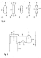
- FIG. 1 Only a very small part of the dental ceramic production device 10 uses - as already shown above - a CAD / CAM device for the provision of a positive model to be embedded. This is in Fig. 1 shown.
- a muffle mandrel 12 extends from a muffle base below the plane of the drawing and ends at an end face 14.
- the muffle base also forms the underside of a muffle, the muffle edge 16 in Fig. 1 is also shown schematically.
- Fig. 1 are generated as positive models using CAD / CAM, namely with a suitable rapid prototyping process, feeder channels and press cavities.
- a ceramic blank is used in the later pressing process, which consists of several types of ceramic with a corresponding transition, for example of two different ceramic materials or ceramics with different colors. The different color distribution is mentioned here as an example.
- the apparent altitude which is specified by the CAM device after user selection, influences the color distribution, in particular the end values.
- the transition can be influenced by a corresponding design of the feeder channel 22, for which purpose the 4a to 4e Reference is made.
- the muffle mandrel 12 has three further grooves 26 to 30. These are intended for receiving additional feeder channels, the groove 30 being equipped with the feeder channel 32 in the example.
- a positive model 34 for forming a mold cavity for an anterior tooth is integrally connected to the feed channel 32.
- Anterior teeth are typically aesthetically more important with regard to the exact shade structure, both in terms of translucency and in terms of adaptation to the neighboring teeth.
- the feed channel 32 has relief projections 35 and 36 which serve to equalize the flow. They can also be chosen larger by the CAM device in order to match the volume of the positive model 34 with the feeder channel 32 to the volume of the positive model 20 with the feeder channel 22 and thus to ensure a simultaneous completion.
- the flow front of the softened dental ceramic fills the press cavities at the same time.
- Fig. 2 it can be seen that the occlusal or incisal sides of the teeth extend downwards, that is to say the lighter ceramic types of the blank must also be oriented downwards in the example.
- the color and brightness of the dental restorations can be influenced by vertical shifting using rapid prototyping; in the example it is provided that the feeder channels 22 and 32 are seated via stops 40 at a vertically predetermined position on the muffle mandrel 12 in the grooves 24 and 30, while in a modified embodiment it is also provided that the relative position between the feeder channel 22 and 32 and the muffle mandrel 12 to vary.
- the distance between the press cavity 34 and the muffle edge 16 is predetermined; this distance is preferably at least 10 mm, even if a smaller distance is shown here for drawing reasons.
- Modern pressing furnaces for pressing dental ceramics typically have so-called underfloor heating. This heater heats the area below the muffle and supplements a ring heater that surrounds the muffle in a ring and primarily ensures the heating of the furnace interior.
- an overflow space 50 is also formed in the upper region, that is to say adjacent to the end face 14, in the groove 24, which also has the The tendency of the softening dental ceramic material to quickly penetrate the area 48 is compensated.
- feeder channel 32 according to FIG Fig. 4a be narrower in area 48 and wider in area 46.
- the feed channel 32 has rounded corners on all sides, so that the flow resistances there are comparatively low.
- a rectangular flow cross section of the flow channel 32 is selected.
- the main braking effects occur there along the corners 52, 54, 56 and 58, but also along the upper side 60 and along the lower side 62.
- the flow front is bulged in the middle and remains clearly behind in the corners 52 to 58.
- Such a configuration leads to the fact that the central area fills the dental ceramic firstly, the central area is initially filled with dental ceramic, so that there is a color spread.
- constricted shape according to Fig. 4e compensates for this using the Fig. 4b Color spread described, since there the flow resistance in the central region 66 is deliberately kept larger.
- feeder channels of which a feeder channel 32 is shown, and positive models, of which a positive model 34 is shown, are produced in one piece.
- a feeder channel base 68 is provided, which extends in a cap-like manner over the muffle mandrel 12.
- the muffle mandrel 12 can be removed particularly easily from the hardened muffle.
- the feeder channel 32 also has a constriction 70 in the incisal region 46, which leads to the color distribution being shifted toward darker colors.
- Fig. 6 is a feeder channel made of wax. It is advantageous here if a circumferential bead 71 is attached, which is flush with the muffle mandrel 12, after the feeder has been introduced into the groove 24 provided on the muffle mandrel. This will make growth much easier. Possible damage to the feeder profile can be effectively prevented.
- the feeder channel is made of a polymer material, for example polyacrylic.
- a predetermined breaking point 72 at the transition point from the fastening groove 24 to the free feed channel, so that after the investment has hardened, the muffle base with the muffle mandrel can be easily released by means of a rotary movement.
Claims (19)
- Dispositif de fabrication de céramique dentaire comprenant un dispositif CAO/FAO pour la réalisation d'une cavité de pressage pour la fabrication de la céramique dentaire, où, au moyen d'un dispositif CAO de celle-ci, la forme de la céramique dentaire à fabriquer peut être déterminée sur la base de données de balayage, et où, au moyen d'un dispositif FAO de celle-ci, un modèle positif peut être fabriqué, sur la base duquel la cavité formée peut être réalisée par l'intermédiaire d'une forme perdue, caractérisé en ce que, au moyen du dispositif FAO, la répartition et la transition entre les différents types de céramique sont également déterminées, c'est-à-dire les types de céramique, qui diffèrent au moins par rapport à un paramètre de matériau, d'aspect, de rigidité ou similaire, peuvent être déterminées automatiquement, où à travers le dispositif FAO pour le réglage de la répartition et de la transition la position, les dimensions et la hauteur relative d'un canal d'alimentation (22, 32) entre un mandrin de moufle (12), qui correspond au canal de pressage, et la cavité de pressage (34), par rapport à la cavité de pressage (34) et au mandrin de moufle (12), peuvent être déterminées et réglées automatiquement pour la fabrication de la céramique dentaire en fonction d'au moins un de ces paramètres.
- Dispositif de production de céramique dentaire selon la revendication 1, caractérisé en ce que le canal d'alimentation (22, 32) sous la forme d'une petite plaque d'une longueur d'au moins 3 mm peut être produit par le dispositif FAO, qui s'étend depuis le mandrin de moufle (12), qui peut être utilisé comme canal de pressage lors du pressage, transversalement à la cavité de pressage (34) pour la céramique dentaire.
- Dispositif de production de céramique dentaire, selon l'une des revendications précédentes, caractérisé en ce que l'angle d'attaque et/ou la position en hauteur entre la cavité de pressage (34) pour la céramique dentaire et le canai d'alimentation (22, 32) peut ou peuvent être déterminé (s) par le dispositif FAO, en particulier à la fois en direction verticale et horizontale.
- Dispositif de production de céramique dentaire selon l'une des revendications précédentes, caractérisé en ce que tant la cavité de pressage (34) que le canal d'alimentation (22, 32), peuvent être fabriqués par le dispositif FAO, en particulier en une seule pièce et de manière générative, de préférence en cire ou en une matière plastique telle que le polyacrylique par prototypage rapide.
- Dispositif de production de céramique dentaire selon l'une des revendications précédentes, caractérisé en ce que la cavité de pressage (34) peut être fixée dans sa position relative verticale par rapport au canal d'alimentation (22, 32) par le dispositif de production (10), en particulier par rapport au centre vertical du canal d'alimentation (22, 32).
- Dispositif de production de céramique dentaire selon l'une des revendications précédentes, caractérisé en ce que l'orientation de la cavité de pressage (34) peut être choisie par le dispositif FAO de manière à orienter le côté incisif/occlusal de la céramique dentaire de la cavité de pressage (34) vers la base du moufle et le côté basal vers l'extrémité du mandrin du moufle (12).
- Dispositif de production de céramique dentaire selon l'une des revendications précédentes, caractérisé en ce qu'un espace virtuel peut être défini par le dispositif FAO, à l'intérieur duquel la cavité de pressage (34) et le canal d'alimentation (22, 32) peuvent s'étendre à l'intérieur du moufle et marque visuellement cet espace annulaire virtuel à l'intérieur du moufle, éventuellement avec l'intervention possible de l'utilisateur par rapport à la position de la cavité de pressage (34) pour la céramique dentaire.
- Dispositif de production de céramique dentaire selon l'une des revendications précédentes, caractérisé en ce que les axes longitudinaux de la cavité de pressage (34) pour la production de la céramique dentaire et du canal d'alimentation en forme de plaque (22, 32) peuvent être alignés parallèlement l'un à l'autre par le dispositif FAO.
- Dispositif de production de céramique dentaire selon l'une des revendications précédentes, caractérisé en ce que les côtés vestibulaires (labiaux ou buccaux) du canal d'alimentation (22, 32) et de la cavité de pressage (34) sont alignés essentiellement à fleur l'un de l'autre et que l'axe horizontal du canal d'alimentation (22, 32) passe par la cavité de pressage (34) mais est dévié dans la direction vestibulaire par rapport à son axe longitudinal.
- Dispositif de production de céramique dentaire selon l'une des revendications précédentes, caractérisé en ce que le point de connexion entre le canal d'alimentation (22, 32) et la cavité de pressage (34) pour produire la céramique dentaire au niveau d'une partie périphérique proximale de la cavité de pressage (34) peut être sélectionné par le dispositif FAO.
- Dispositif de fabrication de céramique dentaire selon l'une des revendications précédentes, caractérisé en ce que la résistance du canal d'alimentation (22, 32) en fonction du volume mathématiquement déterminé de la cavité de pressage (34) peut être déterminé par le dispositif FAO et, au cas où les volumes sont inférieurs à une valeur seuil prédéterminée, des espaces de réduction de pression peuvent être formés au niveau des canaux d'alimentation (22, 32) et/ou au niveau du canal de pressage correspondant au mandrin de moufle (12), qui pendant le pressage déchargent la pression sur la céramique qui avance sous pression isostatique.
- Dispositif de fabrication de céramique dentaire selon l'une des revendications précédentes, caractérisé en ce que la cavité de pressage (34) présente un mandrin pour former un moignon pour la céramique dentaire et en ce que l'axe longitudinal du canal d'alimentation (22, 32) est orienté par rapport à la cavité de pressage (34) de manière à couper la cavité de pressage (34) à l'extérieur du mandrin et/ou que l'axe longitudinal du canal d'alimentation est conçu de manière asymétrique par rapport à l'axe du mandrin.
- Dispositif de production de céramique dentaire selon l'une des revendications précédentes, caractérisé en ce que la hauteur d'un canal d'alimentation (22, 32) correspond à la hauteur d'une pièce pressée, qui est reçue dans le moufle pour la conception d'une céramique dentaire, en particulier multicolore, ou dont la hauteur est au maximum 20% inférieure à celle du mandrin.
- Dispositif de fabrication de céramique dentaire selon l'une des revendications précédentes, caractérisé en ce que le mandrin de moufle (12) est prévu pour recevoir des canaux d'alimentation (22, 32) en forme de plaque, qui présente en particulier au moins deux, de préférence quatre fentes pour recevoir ces derniers, dont l'extension verticale forme une butée pour l'alignement vertical des canaux d'alimentation (22, 32).
- Dispositif de fabrication de céramique dentaire selon la revendication 14, caractérisé en ce que le mandrin de moufle (12) est prévu pour recevoir et supporter les canaux d'alimentation (22, 32) pour les cavités de pressage (34) pour la fabrication de la restauration dentaire, et en ce que les canaux d'alimentation (22, 32) sont reliés entre eux par un capot commun qui est destiné à être logé sur le mandrin de moufle (12).
- Dispositif de production de céramique dentaire selon l'une des revendications précédentes, caractérisé en ce que les différences de viscosité entre les types de céramique peuvent être compensées au moins partiellement par le dispositif FAO au moyen d'espaces de réduction de pression et/ou d'obstacles à l'écoulement, lesquels espaces de réduction de pression et/ou obstacles à l'écoulement sont disposés au niveau du canal de presse, de l'un des canaux d'alimentation (22, 32) ou des deux ou du tout.
- Dispositif de production de céramique dentaire selon l'une des revendications précédentes, caractérisé en ce que le dispositif FAO comporte une bibliothèque de canaux d'alimentation, par laquelle, éventuellement avec l'intervention de l'utilisateur, la répartition et la transition entre les différents types de céramique dans la céramique dentaire peuvent être déterminées sur la base de modèles de répartition ou de transition prédéterminés.
- Dispositif de production de céramique dentaire selon l'une des revendications précédentes, caractérisé en ce qu'un bourrelet périphérique (71) est fixé au canal d'alimentation (32), qui est en particulier à fleur du mandrin de moufle (12) après l'insertion du canal d'alimentation (32) dans la rainure (30) prévue sur le mandrin de moufle (12).
- Dispositif de production de céramique dentaire selon l'une des revendications précédentes, caractérisé en ce que le canal d'alimentation (22) est constitué d'un matériau polymère, par exemple du polyacrylique, et présente un point de rupture prédéterminé (72) en particulier à la transition entre la rainure de fixation (24) et le canal d'alimentation libre (22).
Priority Applications (9)
| Application Number | Priority Date | Filing Date | Title |
|---|---|---|---|
| EP14171444.4A EP2952155B1 (fr) | 2014-06-06 | 2014-06-06 | Dispositif de fabrication de céramique dentaire |
| US15/115,476 US10058405B2 (en) | 2014-06-05 | 2015-05-22 | Dental restoration model |
| CA2946354A CA2946354A1 (fr) | 2014-06-06 | 2015-05-22 | Dispositif de production d'une ceramique dentaire |
| CN201580028401.0A CN106456294B (zh) | 2014-06-05 | 2015-05-22 | 牙科修复模型 |
| PCT/EP2015/061410 WO2015185379A1 (fr) | 2014-06-05 | 2015-05-22 | Modèle de restauration dentaire |
| US15/306,906 US10588727B2 (en) | 2014-06-06 | 2015-05-22 | Device for producing dental ceramic |
| PCT/EP2015/061446 WO2015185381A1 (fr) | 2014-06-06 | 2015-05-22 | Dispositif de production d'une céramique dentaire |
| EP15727331.9A EP3151781B1 (fr) | 2014-06-05 | 2015-05-22 | Modele de restauration dentaire |
| CN201580028013.2A CN106413622B (zh) | 2014-06-06 | 2015-05-22 | 牙科陶瓷件制造装置 |
Applications Claiming Priority (1)
| Application Number | Priority Date | Filing Date | Title |
|---|---|---|---|
| EP14171444.4A EP2952155B1 (fr) | 2014-06-06 | 2014-06-06 | Dispositif de fabrication de céramique dentaire |
Publications (2)
| Publication Number | Publication Date |
|---|---|
| EP2952155A1 EP2952155A1 (fr) | 2015-12-09 |
| EP2952155B1 true EP2952155B1 (fr) | 2020-07-22 |
Family
ID=50942056
Family Applications (1)
| Application Number | Title | Priority Date | Filing Date |
|---|---|---|---|
| EP14171444.4A Active EP2952155B1 (fr) | 2014-06-05 | 2014-06-06 | Dispositif de fabrication de céramique dentaire |
Country Status (5)
| Country | Link |
|---|---|
| US (1) | US10588727B2 (fr) |
| EP (1) | EP2952155B1 (fr) |
| CN (1) | CN106413622B (fr) |
| CA (1) | CA2946354A1 (fr) |
| WO (1) | WO2015185381A1 (fr) |
Families Citing this family (5)
| Publication number | Priority date | Publication date | Assignee | Title |
|---|---|---|---|---|
| EP2952154B1 (fr) * | 2014-06-05 | 2021-05-05 | Ivoclar Vivadent AG | Procédé de fabrication de restaurations dentaires et dispositif de fabrication de céramiques dentaires |
| EP3181090B1 (fr) * | 2014-08-12 | 2022-04-27 | Hangzhou Erran Technology Co. Ltd. | Prothèse dentaire en céramique et son procédé de fabrication |
| EP3064169B1 (fr) * | 2015-03-04 | 2019-04-24 | Ivoclar Vivadent AG | Procédé de fabrication de pièces céramiques dentaires et appareils pour la fabrication de pièces de céramique dentaire |
| EP3870100B1 (fr) * | 2018-10-25 | 2023-09-13 | 3M Innovative Properties Company | Précurseur de couronne dentaire composite imprimé en 3d équipé d'un élément de support et procédé de production |
| CN112606269B (zh) * | 2020-11-26 | 2022-08-09 | 河北凯力华维包装科技有限公司 | 一种可调节进料方式的可降解塑料加工用原料进料装置 |
Family Cites Families (9)
| Publication number | Priority date | Publication date | Assignee | Title |
|---|---|---|---|---|
| BE1008372A3 (nl) | 1994-04-19 | 1996-04-02 | Materialise Nv | Werkwijze voor het vervaardigen van een geperfektioneerd medisch model uitgaande van digitale beeldinformatie van een lichaamsdeel. |
| DE59611075D1 (de) | 1995-12-19 | 2004-10-07 | Ivoclar Vivadent Ag | Verfahren zur Herstellung von Zahnkronen und/oder Zahnbrücken |
| US6345984B2 (en) | 1998-04-13 | 2002-02-12 | Jeneric/Pentron, Inc. | Prefabricated components for dental appliances |
| EP1420714B1 (fr) | 2001-08-31 | 2007-03-21 | Cynovad, Inc. | Procede de production de moules a fondre |
| JP2005059477A (ja) | 2003-08-18 | 2005-03-10 | Shiyoufuu:Kk | 立体構造物製作装置 |
| WO2008058191A2 (fr) * | 2006-11-07 | 2008-05-15 | Geodigm Corporation | Dispositifs de formage de descente de coulée |
| DE102006061143A1 (de) * | 2006-12-22 | 2008-07-24 | Aepsilon Rechteverwaltungs Gmbh | Verfahren, computerlesbares Medium und Computer betreffend die Herstellung von Zahnersatzteilen |
| WO2008103024A1 (fr) * | 2007-02-23 | 2008-08-28 | Oratio B.V. | Procédé de préparation d'une reconstitution dentaire à plusieurs couches en utilisant un intermédiaire de couche occlusale en matériau sacrificiel |
| US7691497B1 (en) * | 2007-04-13 | 2010-04-06 | Ivoclar Vivadent, Inc. | Pressable overlay material for veneering of zirconia and composites thereof |
-
2014
- 2014-06-06 EP EP14171444.4A patent/EP2952155B1/fr active Active
-
2015
- 2015-05-22 CN CN201580028013.2A patent/CN106413622B/zh active Active
- 2015-05-22 WO PCT/EP2015/061446 patent/WO2015185381A1/fr active Application Filing
- 2015-05-22 US US15/306,906 patent/US10588727B2/en active Active
- 2015-05-22 CA CA2946354A patent/CA2946354A1/fr not_active Abandoned
Non-Patent Citations (1)
| Title |
|---|
| None * |
Also Published As
| Publication number | Publication date |
|---|---|
| CN106413622B (zh) | 2019-06-04 |
| WO2015185381A1 (fr) | 2015-12-10 |
| US10588727B2 (en) | 2020-03-17 |
| CA2946354A1 (fr) | 2015-12-10 |
| US20170042647A1 (en) | 2017-02-16 |
| EP2952155A1 (fr) | 2015-12-09 |
| CN106413622A (zh) | 2017-02-15 |
Similar Documents
| Publication | Publication Date | Title |
|---|---|---|
| EP2862539B1 (fr) | Dispositif de positionnement dentaire | |
| EP2952155B1 (fr) | Dispositif de fabrication de céramique dentaire | |
| EP2952154B1 (fr) | Procédé de fabrication de restaurations dentaires et dispositif de fabrication de céramiques dentaires | |
| EP2957252B1 (fr) | Procédé de fabrication d'un modèle réel en trois dimensions de la position réelle d'au moins deux dents d'un patient | |
| EP3041434B1 (fr) | Restauration dentaire | |
| EP0781530A2 (fr) | Méthode de fabrication de couronnes dentaires et/ou de ponts dentaires | |
| EP2410939B1 (fr) | Dispositif de façonnage de gencive et procédé de fabrication de la structure d'un dispositif de façonnage de gencive | |
| EP2065012A1 (fr) | Procédé et système de fabrication de restauration dentaire en céramique | |
| EP3612131B1 (fr) | Procédé de fabrication d'une prothèse dentaire à racines parallèles des dents de la prothèse | |
| WO2015181092A1 (fr) | Dispositif de fabrication d'une prothèse dentaire et prothèse dentaire | |
| DE102017113814B4 (de) | Verfahren zur Herstellung einer Dentalprothese mit definiertem Klebespalt | |
| EP3254641B1 (fr) | Procédé de production d'un appareil de durcissement par rayonnement, d'une fixation et d'un appareil de production de restauration dentaire | |
| EP3572035B1 (fr) | Prothèse dentaire, produit semi-fini associé ainsi que jeu de pièces | |
| WO2012113793A1 (fr) | Procédé de réalisation d'une pluralité de restaurations dentaires | |
| EP3593756B1 (fr) | Procédé de production d'une prothèse ou d'une prothèse partielle | |
| EP3496656B1 (fr) | Procédé pour la production d'une prothèse ou d'une prothèse partielle | |
| EP3157460B1 (fr) | Base de prothèse et procédé pour relier par liaison de matière au moins une dent artificielle à une base de prothèse | |
| WO2015055793A1 (fr) | Gabarit de transfert dentaire | |
| EP3151781B1 (fr) | Modele de restauration dentaire | |
| EP3445274B1 (fr) | Courbure de pas de dent et procede de production d'une courbure de pas de dent | |
| WO2017097908A1 (fr) | Procédé pour produire des restaurations dentaires et dispositif de production de restaurations dentaires ainsi que corps de fraise | |
| DE19850451C1 (de) | Verfahren zur Herstellung von Zahnersatz | |
| EP3064169B1 (fr) | Procédé de fabrication de pièces céramiques dentaires et appareils pour la fabrication de pièces de céramique dentaire | |
| WO2016138994A1 (fr) | Ébauche pour fabriquer des prothèses dentaires qui comporte une zone dentinaire qui est incorporée dans une zone de fusion | |
| DE102017117491A1 (de) | Verfahren zur Erzeugung einer Prothese oder Teilprothese |
Legal Events
| Date | Code | Title | Description |
|---|---|---|---|
| PUAI | Public reference made under article 153(3) epc to a published international application that has entered the european phase |
Free format text: ORIGINAL CODE: 0009012 |
|
| AK | Designated contracting states |
Kind code of ref document: A1 Designated state(s): AL AT BE BG CH CY CZ DE DK EE ES FI FR GB GR HR HU IE IS IT LI LT LU LV MC MK MT NL NO PL PT RO RS SE SI SK SM TR |
|
| AX | Request for extension of the european patent |
Extension state: BA ME |
|
| 17P | Request for examination filed |
Effective date: 20151117 |
|
| RBV | Designated contracting states (corrected) |
Designated state(s): AL AT BE BG CH CY CZ DE DK EE ES FI FR GB GR HR HU IE IS IT LI LT LU LV MC MK MT NL NO PL PT RO RS SE SI SK SM TR |
|
| STAA | Information on the status of an ep patent application or granted ep patent |
Free format text: STATUS: EXAMINATION IS IN PROGRESS |
|
| 17Q | First examination report despatched |
Effective date: 20161214 |
|
| REG | Reference to a national code |
Ref country code: DE Ref legal event code: R079 Ref document number: 502014014486 Country of ref document: DE Free format text: PREVIOUS MAIN CLASS: A61C0013000000 Ipc: A61C0005730000 |
|
| RIC1 | Information provided on ipc code assigned before grant |
Ipc: A61C 13/083 20060101ALI20191213BHEP Ipc: A61C 5/73 20170101AFI20191213BHEP |
|
| GRAP | Despatch of communication of intention to grant a patent |
Free format text: ORIGINAL CODE: EPIDOSNIGR1 |
|
| STAA | Information on the status of an ep patent application or granted ep patent |
Free format text: STATUS: GRANT OF PATENT IS INTENDED |
|
| INTG | Intention to grant announced |
Effective date: 20200207 |
|
| GRAS | Grant fee paid |
Free format text: ORIGINAL CODE: EPIDOSNIGR3 |
|
| GRAA | (expected) grant |
Free format text: ORIGINAL CODE: 0009210 |
|
| STAA | Information on the status of an ep patent application or granted ep patent |
Free format text: STATUS: THE PATENT HAS BEEN GRANTED |
|
| AK | Designated contracting states |
Kind code of ref document: B1 Designated state(s): AL AT BE BG CH CY CZ DE DK EE ES FI FR GB GR HR HU IE IS IT LI LT LU LV MC MK MT NL NO PL PT RO RS SE SI SK SM TR |
|
| REG | Reference to a national code |
Ref country code: GB Ref legal event code: FG4D Free format text: NOT ENGLISH |
|
| REG | Reference to a national code |
Ref country code: CH Ref legal event code: EP |
|
| REG | Reference to a national code |
Ref country code: DE Ref legal event code: R096 Ref document number: 502014014486 Country of ref document: DE |
|
| REG | Reference to a national code |
Ref country code: AT Ref legal event code: REF Ref document number: 1292660 Country of ref document: AT Kind code of ref document: T Effective date: 20200815 |
|
| REG | Reference to a national code |
Ref country code: IE Ref legal event code: FG4D Free format text: LANGUAGE OF EP DOCUMENT: GERMAN |
|
| REG | Reference to a national code |
Ref country code: CH Ref legal event code: NV Representative=s name: KELLER SCHNEIDER PATENT- UND MARKENANWAELTE AG, CH |
|
| REG | Reference to a national code |
Ref country code: SE Ref legal event code: TRGR |
|
| REG | Reference to a national code |
Ref country code: LT Ref legal event code: MG4D |
|
| PG25 | Lapsed in a contracting state [announced via postgrant information from national office to epo] |
Ref country code: NO Free format text: LAPSE BECAUSE OF FAILURE TO SUBMIT A TRANSLATION OF THE DESCRIPTION OR TO PAY THE FEE WITHIN THE PRESCRIBED TIME-LIMIT Effective date: 20201022 Ref country code: FI Free format text: LAPSE BECAUSE OF FAILURE TO SUBMIT A TRANSLATION OF THE DESCRIPTION OR TO PAY THE FEE WITHIN THE PRESCRIBED TIME-LIMIT Effective date: 20200722 Ref country code: GR Free format text: LAPSE BECAUSE OF FAILURE TO SUBMIT A TRANSLATION OF THE DESCRIPTION OR TO PAY THE FEE WITHIN THE PRESCRIBED TIME-LIMIT Effective date: 20201023 Ref country code: LT Free format text: LAPSE BECAUSE OF FAILURE TO SUBMIT A TRANSLATION OF THE DESCRIPTION OR TO PAY THE FEE WITHIN THE PRESCRIBED TIME-LIMIT Effective date: 20200722 Ref country code: HR Free format text: LAPSE BECAUSE OF FAILURE TO SUBMIT A TRANSLATION OF THE DESCRIPTION OR TO PAY THE FEE WITHIN THE PRESCRIBED TIME-LIMIT Effective date: 20200722 Ref country code: PT Free format text: LAPSE BECAUSE OF FAILURE TO SUBMIT A TRANSLATION OF THE DESCRIPTION OR TO PAY THE FEE WITHIN THE PRESCRIBED TIME-LIMIT Effective date: 20201123 Ref country code: BG Free format text: LAPSE BECAUSE OF FAILURE TO SUBMIT A TRANSLATION OF THE DESCRIPTION OR TO PAY THE FEE WITHIN THE PRESCRIBED TIME-LIMIT Effective date: 20201022 Ref country code: ES Free format text: LAPSE BECAUSE OF FAILURE TO SUBMIT A TRANSLATION OF THE DESCRIPTION OR TO PAY THE FEE WITHIN THE PRESCRIBED TIME-LIMIT Effective date: 20200722 |
|
| PG25 | Lapsed in a contracting state [announced via postgrant information from national office to epo] |
Ref country code: LV Free format text: LAPSE BECAUSE OF FAILURE TO SUBMIT A TRANSLATION OF THE DESCRIPTION OR TO PAY THE FEE WITHIN THE PRESCRIBED TIME-LIMIT Effective date: 20200722 Ref country code: PL Free format text: LAPSE BECAUSE OF FAILURE TO SUBMIT A TRANSLATION OF THE DESCRIPTION OR TO PAY THE FEE WITHIN THE PRESCRIBED TIME-LIMIT Effective date: 20200722 Ref country code: RS Free format text: LAPSE BECAUSE OF FAILURE TO SUBMIT A TRANSLATION OF THE DESCRIPTION OR TO PAY THE FEE WITHIN THE PRESCRIBED TIME-LIMIT Effective date: 20200722 Ref country code: IS Free format text: LAPSE BECAUSE OF FAILURE TO SUBMIT A TRANSLATION OF THE DESCRIPTION OR TO PAY THE FEE WITHIN THE PRESCRIBED TIME-LIMIT Effective date: 20201122 |
|
| PG25 | Lapsed in a contracting state [announced via postgrant information from national office to epo] |
Ref country code: NL Free format text: LAPSE BECAUSE OF FAILURE TO SUBMIT A TRANSLATION OF THE DESCRIPTION OR TO PAY THE FEE WITHIN THE PRESCRIBED TIME-LIMIT Effective date: 20200722 |
|
| REG | Reference to a national code |
Ref country code: DE Ref legal event code: R097 Ref document number: 502014014486 Country of ref document: DE |
|
| PG25 | Lapsed in a contracting state [announced via postgrant information from national office to epo] |
Ref country code: CZ Free format text: LAPSE BECAUSE OF FAILURE TO SUBMIT A TRANSLATION OF THE DESCRIPTION OR TO PAY THE FEE WITHIN THE PRESCRIBED TIME-LIMIT Effective date: 20200722 Ref country code: DK Free format text: LAPSE BECAUSE OF FAILURE TO SUBMIT A TRANSLATION OF THE DESCRIPTION OR TO PAY THE FEE WITHIN THE PRESCRIBED TIME-LIMIT Effective date: 20200722 Ref country code: EE Free format text: LAPSE BECAUSE OF FAILURE TO SUBMIT A TRANSLATION OF THE DESCRIPTION OR TO PAY THE FEE WITHIN THE PRESCRIBED TIME-LIMIT Effective date: 20200722 Ref country code: RO Free format text: LAPSE BECAUSE OF FAILURE TO SUBMIT A TRANSLATION OF THE DESCRIPTION OR TO PAY THE FEE WITHIN THE PRESCRIBED TIME-LIMIT Effective date: 20200722 Ref country code: SM Free format text: LAPSE BECAUSE OF FAILURE TO SUBMIT A TRANSLATION OF THE DESCRIPTION OR TO PAY THE FEE WITHIN THE PRESCRIBED TIME-LIMIT Effective date: 20200722 |
|
| PLBE | No opposition filed within time limit |
Free format text: ORIGINAL CODE: 0009261 |
|
| STAA | Information on the status of an ep patent application or granted ep patent |
Free format text: STATUS: NO OPPOSITION FILED WITHIN TIME LIMIT |
|
| PG25 | Lapsed in a contracting state [announced via postgrant information from national office to epo] |
Ref country code: AL Free format text: LAPSE BECAUSE OF FAILURE TO SUBMIT A TRANSLATION OF THE DESCRIPTION OR TO PAY THE FEE WITHIN THE PRESCRIBED TIME-LIMIT Effective date: 20200722 |
|
| 26N | No opposition filed |
Effective date: 20210423 |
|
| PG25 | Lapsed in a contracting state [announced via postgrant information from national office to epo] |
Ref country code: SK Free format text: LAPSE BECAUSE OF FAILURE TO SUBMIT A TRANSLATION OF THE DESCRIPTION OR TO PAY THE FEE WITHIN THE PRESCRIBED TIME-LIMIT Effective date: 20200722 |
|
| PG25 | Lapsed in a contracting state [announced via postgrant information from national office to epo] |
Ref country code: SI Free format text: LAPSE BECAUSE OF FAILURE TO SUBMIT A TRANSLATION OF THE DESCRIPTION OR TO PAY THE FEE WITHIN THE PRESCRIBED TIME-LIMIT Effective date: 20200722 |
|
| REG | Reference to a national code |
Ref country code: NL Ref legal event code: MP Effective date: 20200722 |
|
| PG25 | Lapsed in a contracting state [announced via postgrant information from national office to epo] |
Ref country code: MC Free format text: LAPSE BECAUSE OF FAILURE TO SUBMIT A TRANSLATION OF THE DESCRIPTION OR TO PAY THE FEE WITHIN THE PRESCRIBED TIME-LIMIT Effective date: 20200722 |
|
| REG | Reference to a national code |
Ref country code: BE Ref legal event code: MM Effective date: 20210630 |
|
| PG25 | Lapsed in a contracting state [announced via postgrant information from national office to epo] |
Ref country code: LU Free format text: LAPSE BECAUSE OF NON-PAYMENT OF DUE FEES Effective date: 20210606 |
|
| PG25 | Lapsed in a contracting state [announced via postgrant information from national office to epo] |
Ref country code: IE Free format text: LAPSE BECAUSE OF NON-PAYMENT OF DUE FEES Effective date: 20210606 |
|
| PG25 | Lapsed in a contracting state [announced via postgrant information from national office to epo] |
Ref country code: BE Free format text: LAPSE BECAUSE OF NON-PAYMENT OF DUE FEES Effective date: 20210630 |
|
| PG25 | Lapsed in a contracting state [announced via postgrant information from national office to epo] |
Ref country code: HU Free format text: LAPSE BECAUSE OF FAILURE TO SUBMIT A TRANSLATION OF THE DESCRIPTION OR TO PAY THE FEE WITHIN THE PRESCRIBED TIME-LIMIT; INVALID AB INITIO Effective date: 20140606 |
|
| PG25 | Lapsed in a contracting state [announced via postgrant information from national office to epo] |
Ref country code: CY Free format text: LAPSE BECAUSE OF FAILURE TO SUBMIT A TRANSLATION OF THE DESCRIPTION OR TO PAY THE FEE WITHIN THE PRESCRIBED TIME-LIMIT Effective date: 20200722 |
|
| P01 | Opt-out of the competence of the unified patent court (upc) registered |
Effective date: 20230607 |
|
| PGFP | Annual fee paid to national office [announced via postgrant information from national office to epo] |
Ref country code: IT Payment date: 20230426 Year of fee payment: 10 Ref country code: FR Payment date: 20230508 Year of fee payment: 10 Ref country code: DE Payment date: 20230522 Year of fee payment: 10 |
|
| PGFP | Annual fee paid to national office [announced via postgrant information from national office to epo] |
Ref country code: SE Payment date: 20230509 Year of fee payment: 10 Ref country code: AT Payment date: 20230509 Year of fee payment: 10 |
|
| PGFP | Annual fee paid to national office [announced via postgrant information from national office to epo] |
Ref country code: GB Payment date: 20230508 Year of fee payment: 10 Ref country code: CH Payment date: 20230702 Year of fee payment: 10 |
|
| PG25 | Lapsed in a contracting state [announced via postgrant information from national office to epo] |
Ref country code: MK Free format text: LAPSE BECAUSE OF FAILURE TO SUBMIT A TRANSLATION OF THE DESCRIPTION OR TO PAY THE FEE WITHIN THE PRESCRIBED TIME-LIMIT Effective date: 20200722 |