EP2952155B1 - Dental ceramic production device - Google Patents
Dental ceramic production device Download PDFInfo
- Publication number
- EP2952155B1 EP2952155B1 EP14171444.4A EP14171444A EP2952155B1 EP 2952155 B1 EP2952155 B1 EP 2952155B1 EP 14171444 A EP14171444 A EP 14171444A EP 2952155 B1 EP2952155 B1 EP 2952155B1
- Authority
- EP
- European Patent Office
- Prior art keywords
- dental ceramic
- feeder
- muffle
- channel
- pressing cavity
- Prior art date
- Legal status (The legal status is an assumption and is not a legal conclusion. Google has not performed a legal analysis and makes no representation as to the accuracy of the status listed.)
- Active
Links
Images


Classifications
-
- A—HUMAN NECESSITIES
- A61—MEDICAL OR VETERINARY SCIENCE; HYGIENE
- A61C—DENTISTRY; APPARATUS OR METHODS FOR ORAL OR DENTAL HYGIENE
- A61C5/00—Filling or capping teeth
- A61C5/70—Tooth crowns; Making thereof
- A61C5/73—Composite crowns
-
- A—HUMAN NECESSITIES
- A61—MEDICAL OR VETERINARY SCIENCE; HYGIENE
- A61C—DENTISTRY; APPARATUS OR METHODS FOR ORAL OR DENTAL HYGIENE
- A61C13/00—Dental prostheses; Making same
- A61C13/0003—Making bridge-work, inlays, implants or the like
- A61C13/0004—Computer-assisted sizing or machining of dental prostheses
-
- A—HUMAN NECESSITIES
- A61—MEDICAL OR VETERINARY SCIENCE; HYGIENE
- A61C—DENTISTRY; APPARATUS OR METHODS FOR ORAL OR DENTAL HYGIENE
- A61C13/00—Dental prostheses; Making same
- A61C13/0003—Making bridge-work, inlays, implants or the like
- A61C13/0006—Production methods
- A61C13/0019—Production methods using three dimensional printing
-
- A—HUMAN NECESSITIES
- A61—MEDICAL OR VETERINARY SCIENCE; HYGIENE
- A61C—DENTISTRY; APPARATUS OR METHODS FOR ORAL OR DENTAL HYGIENE
- A61C13/00—Dental prostheses; Making same
- A61C13/0003—Making bridge-work, inlays, implants or the like
- A61C13/0022—Blanks or green, unfinished dental restoration parts
-
- A—HUMAN NECESSITIES
- A61—MEDICAL OR VETERINARY SCIENCE; HYGIENE
- A61C—DENTISTRY; APPARATUS OR METHODS FOR ORAL OR DENTAL HYGIENE
- A61C13/00—Dental prostheses; Making same
- A61C13/08—Artificial teeth; Making same
- A61C13/081—Making teeth by casting or moulding
-
- A—HUMAN NECESSITIES
- A61—MEDICAL OR VETERINARY SCIENCE; HYGIENE
- A61C—DENTISTRY; APPARATUS OR METHODS FOR ORAL OR DENTAL HYGIENE
- A61C13/00—Dental prostheses; Making same
- A61C13/08—Artificial teeth; Making same
- A61C13/082—Cosmetic aspects, e.g. inlays; Determination of the colour
-
- A—HUMAN NECESSITIES
- A61—MEDICAL OR VETERINARY SCIENCE; HYGIENE
- A61C—DENTISTRY; APPARATUS OR METHODS FOR ORAL OR DENTAL HYGIENE
- A61C13/00—Dental prostheses; Making same
- A61C13/08—Artificial teeth; Making same
- A61C13/083—Porcelain or ceramic teeth
-
- A—HUMAN NECESSITIES
- A61—MEDICAL OR VETERINARY SCIENCE; HYGIENE
- A61C—DENTISTRY; APPARATUS OR METHODS FOR ORAL OR DENTAL HYGIENE
- A61C5/00—Filling or capping teeth
- A61C5/70—Tooth crowns; Making thereof
- A61C5/77—Methods or devices for making crowns
-
- B—PERFORMING OPERATIONS; TRANSPORTING
- B28—WORKING CEMENT, CLAY, OR STONE
- B28B—SHAPING CLAY OR OTHER CERAMIC COMPOSITIONS; SHAPING SLAG; SHAPING MIXTURES CONTAINING CEMENTITIOUS MATERIAL, e.g. PLASTER
- B28B7/00—Moulds; Cores; Mandrels
- B28B7/0097—Press moulds; Press-mould and press-ram assemblies
-
- B—PERFORMING OPERATIONS; TRANSPORTING
- B33—ADDITIVE MANUFACTURING TECHNOLOGY
- B33Y—ADDITIVE MANUFACTURING, i.e. MANUFACTURING OF THREE-DIMENSIONAL [3-D] OBJECTS BY ADDITIVE DEPOSITION, ADDITIVE AGGLOMERATION OR ADDITIVE LAYERING, e.g. BY 3-D PRINTING, STEREOLITHOGRAPHY OR SELECTIVE LASER SINTERING
- B33Y80/00—Products made by additive manufacturing
-
- A—HUMAN NECESSITIES
- A61—MEDICAL OR VETERINARY SCIENCE; HYGIENE
- A61C—DENTISTRY; APPARATUS OR METHODS FOR ORAL OR DENTAL HYGIENE
- A61C2201/00—Material properties
- A61C2201/002—Material properties using colour effect, e.g. for identification purposes
-
- B—PERFORMING OPERATIONS; TRANSPORTING
- B29—WORKING OF PLASTICS; WORKING OF SUBSTANCES IN A PLASTIC STATE IN GENERAL
- B29K—INDEXING SCHEME ASSOCIATED WITH SUBCLASSES B29B, B29C OR B29D, RELATING TO MOULDING MATERIALS OR TO MATERIALS FOR MOULDS, REINFORCEMENTS, FILLERS OR PREFORMED PARTS, e.g. INSERTS
- B29K2091/00—Use of waxes as moulding material
-
- B—PERFORMING OPERATIONS; TRANSPORTING
- B29—WORKING OF PLASTICS; WORKING OF SUBSTANCES IN A PLASTIC STATE IN GENERAL
- B29L—INDEXING SCHEME ASSOCIATED WITH SUBCLASS B29C, RELATING TO PARTICULAR ARTICLES
- B29L2031/00—Other particular articles
- B29L2031/753—Medical equipment; Accessories therefor
-
- B—PERFORMING OPERATIONS; TRANSPORTING
- B29—WORKING OF PLASTICS; WORKING OF SUBSTANCES IN A PLASTIC STATE IN GENERAL
- B29L—INDEXING SCHEME ASSOCIATED WITH SUBCLASS B29C, RELATING TO PARTICULAR ARTICLES
- B29L2031/00—Other particular articles
- B29L2031/757—Moulds, cores, dies
Description
Die Erfindung betrifft eine Dentalkeramik-Erzeugungsvorrichtung.The invention relates to a dental ceramic production device.
Es ist seit längerem bekannt, unter Verwendung von dreidimensionalen Scandaten aus dem Mund eines Patienten eine Dentalrestauration herzustellen. Ein Beispiel hierfür ist das aus der
Es ist auch seit langem bekannt, Keramiken, die sich in mindestens einem Parameter unterscheiden, in geeigneter Weise zusammenzuführen und zusammen für die Bereitstellung der Dentalrestauration zu verwenden. So ist gemäß der
Ein weiteres Beispiel für unterschiedliche Dentalkeramikmaterialien, auch mit Füllstoffen, die auch miteinander kombiniert werden können, lässt sich aus der
Ferner ist es bereits vorgeschlagen worden, zwei unterschiedlich gefärbte Keramikmassen zusammenzupressen und an dem Zubringerkanal an geeigneter Stelle eine Ausbuchtung anzubringen, um dadurch den Anteil einer der Keramikmassen an der fertigen Dentalrestauration zu reduzieren. Diese Lösung hat sich jedoch in der Praxis ebenfalls nicht durchgesetzt; für die Festlegung des Übergangs sind meist Probepressungen erforderlich, so dass dieses Verfahren vom Aufwand her nicht gerechtfertigt ist.Furthermore, it has already been proposed to press two differently colored ceramic masses together and to provide a bulge on the feeder channel at a suitable point, to thereby reduce the proportion of one of the ceramic materials in the finished dental restoration. However, this solution has also not become established in practice; Trial pressures are usually required to determine the transition, so that this procedure is not justified in terms of effort.
Demgegenüber liegt der Erfindung die Aufgabe zugrunde, eine Dentalkeramik-Erzeugungsvorrichtung bereitzustellen, die leichter zu beherrschen ist und zuverlässig die Erzeugung einer Dentalkeramik aus mindestens zwei unterschiedlichen Keramikarten ermöglicht.In contrast, the object of the invention is to provide a dental ceramic production device which is easier to control and reliably enables the production of a dental ceramic from at least two different types of ceramic.
Diese Aufgabe wird erfindungsgemäß durch Anspruch 1 gelöst. Vorteilhafte Weiterbildungen ergeben sich aus den Unteransprüchen.This object is achieved by claim 1. Advantageous further developments result from the subclaims.
Erfindungsgemäß besonders günstig ist es, dass die CAM-Vorrichtung eine automatische Festlegung der Verteilung und des Übergangs zwischen den verschiedenen Keramikarten vornimmt. Dies geschieht, indem die Lage des Zubringerkanals, die Abmessungen des Zubringerkanals, die relative Höhe des Zubringerkanals bezogen auf den Presshohlraum einerseits, aber auch auf den Muffeldorn, der dem Presskanal entspricht, andererseits von der CAM-Vorrichtung beim Erstellen des Positivmodells automatisch eingestellt wird.According to the invention, it is particularly favorable that the CAM device automatically determines the distribution and transition between the different types of ceramic. This is done by automatically adjusting the position of the feeder channel, the dimensions of the feeder channel, the relative height of the feeder channel in relation to the press cavity on the one hand, but also to the muffle mandrel that corresponds to the press channel on the other hand by the CAM device when creating the positive model.
Dies geschieht, indem die Lage des Zubringerkanals, der dem Presskanal entspricht, die Abmessungen des Zubringerkanals, die relative Höhe des Zubringerkanals bezogen auf den Muffeldorn einerseits, aber auch auf den Presshohlraum andererseits von der CAM-Vorrichtung beim Erstellen des Positivmodells automatisch eingestellt wird.This is done by automatically adjusting the position of the feeder channel that corresponds to the press channel, the dimensions of the feeder channel, the relative height of the feeder channel in relation to the muffle mandrel on the one hand, but also to the press cavity on the other hand when the positive model is created.
Hierzu wird zunächst ein Rohling mit einer vorbekannten Verteilung von Keramikarten, die sich mindestens hinsichtlich eines Parameters unterscheiden, verwendet. Die Dentalrestauration soll nun erfindungsgemäß ebenfalls aus mindestens zwei Keramikarten bestehen, aber die Verteilung und der Übergang müssen nicht mit der Verteilung und dem Übergang bei dem Keramikrohling übereinstimmen. Hierzu wird erfindungsgemäß vielmehr in überraschend einfacher Weise der Zubringerkanal verwendet, der von der CAM-Vorrichtung zielkonform bereitgestellt wird. Beispielsweise ergibt eine im Querschnitt keilförmige Ausgestaltung des Zubringerkanals, dass die der Keilspitze benachbarte Keramikart einen größeren Strömungswiderstand hat, so dass sich der Übergang und die Verteilung bei der Dentalrestauration stärker zu der anderen Art hin verlagert.For this purpose, a blank with a previously known distribution of ceramic types that differ in at least one parameter is first used. According to the invention, the dental restoration should now also consist of at least two types of ceramic, but the distribution and the transition do not have to match the distribution and the transition in the ceramic blank. To this end, according to the invention, the feeder channel, which is provided by the CAM device in accordance with the target, is used in a surprisingly simple manner. For example, a configuration of the feeder channel that is wedge-shaped in cross section means that the type of ceramic adjacent to the wedge tip has a greater flow resistance, so that the transition and the distribution during dental restoration shift more towards the other type.
Damit besteht auch die Möglichkeit, zwei sehr unterschiedliche Keramikarten zu verwenden, die sich beispielsweise hinsichtlich eines Parameters um 80% unterscheiden, aber durch eine geringere Höhe des Zubringerkanals einen Unterschied von lediglich beispielsweise 40% bei den Keramikarten der Dentalkeramik einzustellen.This also makes it possible to use two very different types of ceramic, which differ, for example, in terms of a parameter by 80%, but, due to a lower height of the feeder channel, set a difference of only, for example, 40% for the types of ceramic in the dental ceramic.
Nachdem die CAM-Vorrichtung per Rapid-Prototyping oder auch auf beliebige andere geeignete Weise den Zubringerkanal zusammen mit dem Press-Hohlraum erzeugt, ist es leicht möglich, vorab und damit fehlerfrei eine entsprechende Relativposition zu gewährleisten, und damit auch die Verteilung und den Übergang - ohne die Notwendigkeit der manuellen Nachbearbeitung - automatisch vorzugeben.After the CAM device generates the feeder channel together with the press cavity by rapid prototyping or in any other suitable way, it is easily possible to ensure a corresponding relative position beforehand and thus without errors, and thus also the distribution and the transition - without the need for manual post-processing - automatically specified.
Es ist beispielsweise auch ohne Weiteres möglich, eine seitliche Einschnürung in dem Zubringerkanal vorzusehen, die beispielsweise bauchig ausgebildet sein kann, und hierdurch eine Spreizung der Verteilung und des Übergangs an der Dentalkeramik im Vergleich zu dem Rohling zu realisieren.For example, it is also readily possible to provide a lateral constriction in the feeder channel, which can be bulged, for example, and thereby to achieve a spreading of the distribution and the transition on the dental ceramic compared to the blank.
Typischerweise weist ein erfindungsgemäßer Zubringerkanal eine Höhe auf, die wesentlich größer als seine Stärke ist. Mit Höhe ist die Richtung des Änderungsverlaufs der Keramikarten, und zwar sowohl bei dem Pressrohling als auch bei der Dentalrestauration gemeint. Typischerweise werden über den Zubringerkanal dementsprechend obere Bereiche des Pressrohlings oberen Bereichen der Dentalkeramik zugeführt, und umgekehrt untere Bereiche der Dentalkeramik unteren Bereichen des Pressrohlings.A feed channel according to the invention typically has a height which is substantially greater than its strength. Height is the direction of the change in the ceramic types, both in the pressed blank and in the dental restoration. Typically, upper regions of the press blank are accordingly fed to upper regions of the dental ceramic via the feed channel, and conversely lower regions of the dental ceramic are supplied to lower regions of the press blank.
In vorteilhafter Ausgestaltung der erfindungsgemäßen Vorrichtung ist es vorgesehen, dass sich mehrere Dentalrestaurationen zusammen mit entsprechenden Zubringerkanälen von dem Presskanal oder Muffeldorn weg erstrecken. Die Zubringerkanäle können über eine gemeinsame Zubringerbasis miteinander verbunden sein und gemeinsam per Rapid-Prototyping - oder aber auch per Fräsen - hergestellt sein. Alternativ kann auch jeder Zubringerkanal zusammen mit dem zugehörigen Positivmodell der Dentalrestauration separat hergestellt werden, wobei dann die Zubringerkanäle mit ihren Einströmenden an dem Muffeldorn befestigt werden, der dann zugleich einen entsprechenden Höhenanschlag bietet.In an advantageous embodiment of the device according to the invention, it is provided that a plurality of dental restorations, together with corresponding feeder channels, extend away from the press channel or muffle mandrel. The feeder channels can be connected to one another via a common feeder base and can be produced together by rapid prototyping - or else by milling. Alternatively, each feeder channel can also be produced together with the associated positive model of the dental restoration, in which case the feeder channels are then attached to the muffle mandrel with their inflowing ends, which then also offers a corresponding height stop.
Die Dentalrestaurationen erstrecken sich bevorzugt kreisförmig um den Muffeldorn bzw. den entsprechenden Presskanal herum und halten einen Randabstand zur Außenwand der Muffel ein, welcher 10mm nicht unterschreiten sollte. Zugleich halten die Dentalrestaurationen auch zueinander einen Abstand von beispielsweise 3 oder 4 mm ein.The dental restorations preferably extend in a circle around the muffle mandrel or the corresponding press channel and maintain an edge distance from the outer wall of the muffle which should not be less than 10 mm. At the same time, the dental restorations also keep a distance of, for example, 3 or 4 mm.
Nach Erstellung der Anordnung von Dentalrestaurationen und Zubringerkanälen per Rapid-Prototyping wird diese Anordnung in geeigneter Weise auf dem Muffeldorn angebracht und dort befestigt. In an sich bekannter Weise wird ein Silikonring auf eine Muffelbasis aufgeschoben und dann die Einheit aus Muffelbasis, Muffeldorn und vorgefertigten Positivmodellen einschließlich der Zubringerkanäle mittels einer geeigneten aushärtbaren Masse wie einer phosphatgebundenen Einbettmasse vergossen; bei niedrigen Presstemperaturen ist auch eine Gipsverbindung geeignetAfter creating the arrangement of dental restorations and feeder channels using rapid prototyping, this arrangement is attached to the muffle mandrel in a suitable manner and fastened there. In a manner known per se, a silicone ring is pushed onto a muffle base and then the unit consisting of muffle base, muffle mandrel and prefabricated positive models, including the feeder channels, is cast using a suitable curable material, such as a phosphate-bonded investment material; a plaster joint is also suitable at low pressing temperatures
Nach Erhärten der Masse wird der Silikonring entfernt, und die Muffelbasis zusammen mit dem Muffeldorn herausgezogen. Hierbei trennt sich die per Rapid-Prototyping erstellte Anordnung von dem Muffeldorn und verbleibt in der Muffel.After the mass has hardened, the silicone ring is removed and the muffle base pulled out together with the muffle mandrel. The arrangement created by rapid prototyping separates from the muffle mandrel and remains in the muffle.
Sie besteht aus einer rückstandsfrei entfernbaren Masse. Hierzu wird die Muffel auf eine geeignete Temperatur gebracht, bei welcher das Material der Positivmodelle schmilzt oder sogar verdampft, oder rückstandsfrei verbrennt.It consists of a mass that can be removed without leaving any residue. For this purpose, the muffle is brought to a suitable temperature at which the material of the positive models melts or even evaporates, or burns without residue.
Nach diesem Schritt verbleiben die Press-Hohlräume und der Presskanal an der Stelle, an der sich zuvor der Muffeldorn erstreckte. Zwischen diesen sind die erfindungsgemäß ausgebildeten Zubringerkanäle vorgesehen.After this step, the press cavities and the press channel remain at the location where the muffle mandrel previously extended. Between these, the feeder channels designed according to the invention are provided.
Die Muffel wird nun typischerweise umgedreht, nachdem die für die Dentaltechnik verwendeten Pressöfen einen Pressstempel aufweisen, der sich von oben nach unten bewegt. Nach Einbringen eines Mehrkeramikrohlings wird eine Distanzscheibe oder ein Distanzzylinder oder beides, z.B. aus Aluminiumoxid oder aus einer phosphatgebundenen Einbettmasse, eingeführt, und hieran anschließend die vorgewärmte Muffel in den Pressofen gebracht, wo sie auf die Presstemperatur gebracht wird.The muffle is now typically turned over after the press furnaces used for dental technology have a press stamp which moves from top to bottom. After inserting a multi-ceramic blank, a spacer or a distance cylinder or both, e.g. made of aluminum oxide or a phosphate-bonded investment, and then the preheated muffle is brought into the press furnace, where it is brought to the pressing temperature.
Durch Erwärmung wird die Keramik nun zähflüssig und aufgrund des von dem Pressstempel ausgeübten Drucks fließt sie durch die Zubringerkanäle in die Presshohlräume.The ceramic now becomes viscous due to heating and due to the pressure exerted by the press ram, it flows through the feeder channels into the press cavities.
Die hier zur Rede stehenden Temperaturen betragen zwischen 850° C bei Lithiumdisilikatkeramiken und 1200 °C bei z.B. Leuzitglaskeramiken oder Oxidkeramiken.The temperatures in question here are between 850 ° C for lithium disilicate ceramics and 1200 ° C for e.g. Leucite glass ceramics or oxide ceramics.
Bei einstückiger Fertigung der Anordnung aus Zubringerkanälen und Positivmodellen lässt sich der erfindungsgemäß gegebenenfalls erwünschte Höhenversatz sowohl ausgangsseitig aber bevorzugt eingangsseitig des Zubringerkanals realisieren und gegebenenfalls auch an beiden Seiten. Ferner bestehen große Freiräume in der Wahl der Form des Zubringerkanals.When the arrangement of feeder channels and positive models is manufactured in one piece, the height offset which may be desired according to the invention can be implemented both on the output side but preferably on the input side of the feeder channel and, if appropriate, also on both sides. There is also great freedom in the choice of the shape of the feeder channel.
Die besondere Aufgabe der CAM-Vorrichtung besteht erfindungsgemäß darin, die Form des Zubringerkanals dergestalt auszuwählen, dass ein ästhetisch besonders ansprechendes Ergebnis, aber auch ein den Belassungserfordernissen der Dentalrestaurationen entsprechendes Ergebnis bereitgestellt wird. Bei hinsichtlich des Materials unterschiedlichen Keramikarten trägt die CAM-Vorrichtung dafür Sorge, dass das als Verstärkungselement eingesetzte Material, wie beispielweise eine Oxidkeramik, in ausreichendem Maße der Dentalrestauration, also dem Press-Hohlraum für diese, zugeführt wird.According to the invention, the special task of the CAM device is to select the shape of the feeder channel in such a way that an aesthetically particularly appealing result is provided, but also a result that corresponds to the retention requirements of the dental restorations. In the case of different types of ceramic with regard to the material, the CAM device ensures that the material used as the reinforcing element, such as an oxide ceramic, is supplied to the dental restoration, that is to say the press cavity for it, to a sufficient extent.
Hierzu ist der Strömungsquerschnitt des Zubringerkanals an der Stirnfläche des Presskanals oder diesem Bereich benachbart ausreichend breit. Typischerweise wird das dunklere und/oder härtere Keramikmaterial endseitig des Presskanals, also bei einer Muffelanordnung, bei der die Muffelbasis unten ist, oben zugeführt, wobei der Press-Hohlraum so ausgerichtet ist, dass der Inzisal- bzw. Okklusalbereich dann unten ist.For this purpose, the flow cross-section of the feeder channel on the end face of the press channel or adjacent to this area is sufficiently wide. The darker and / or harder ceramic material is typically fed in at the end of the press channel, that is to say in a muffle arrangement in which the muffle base is at the bottom, the press cavity being oriented such that the incisal or occlusal area is then at the bottom.
Diese Betrachtung wird hier allgemein zugrundegelegt, wobei es sich versteht, dass beim Pressen die Muffel um 180° gedreht wird; diese Position wird hier jedoch nicht weiter erläutert.This consideration is generally used here, it being understood that the muffle is rotated by 180 ° during pressing; however, this position is not further explained here.
Der Pressrohling - und damit auch die fertige Dentalkeramik - weist dann unten die weichere und/oder hellere Keramik auf, und die vertikale Relativposition zwischen dem Zubringerkanal und dem Presshohlraum beeinflusst die Strömung in diesen, und damit die Verteilung der Keramikarten in der Dentalrestauration. Aufgrund der Reibungseffekte zwischen dem oberen und unteren Ende des Zubringerkanals wird der Keramikstrom dort je gebremst, so dass die Keramikströmungsfront typischerweise bauchig ist, also mittig vorgewölbt.The press blank - and thus also the finished dental ceramic - then has the softer and / or lighter ceramic at the bottom, and the vertical relative position between the feed channel and the press cavity influences the flow in these, and thus the distribution of the types of ceramic in the dental restoration. Due to the frictional effects between the upper and lower ends of the feeder channel, the ceramic flow is slowed down there, so that the ceramic flow front is typically bulbous, that is, bulging in the middle.
Um dieser Erscheinung zu begegnen, kann auch eine mittige Einschnürung des Zubringerkanals vorgesehen sein.In order to counter this phenomenon, a central constriction of the feeder channel can also be provided.
In weiterer vorteilhafter Ausgestaltung ist ein oder sind mehrere Entlastungsvorsprünge vorgesehen, die sich entlang der Längsseite des Zubringerkanals quer zur Strömungsrichtung erstrecken und in welche die Dentalkeramik vor dem Weiterströmen eintritt. Hierdurch lässt sich eine Strömungsvergleichmäßigung erzeugen.In a further advantageous embodiment, one or more relief projections are provided, which extend along the longitudinal side of the feeder channel transversely to the direction of flow and into which the dental ceramic enters before it continues to flow. This allows a flow equalization to be generated.
In einer weiter bevorzugten Ausgestaltung ist es vorgesehen, den Zubringerkanal in Verlängerung der inzisalen bzw. okklusalen Schwerpunktserstreckung anzubringen. Bei Molaren bietet sich hierzu der mesiobukkale Höcker an, wobei sich der Zubringerkanal dann bevorzugt im Wesentlichen mesial von diesem ausgehend erstreckt, jedoch bevorzugt leicht schräg, gleichsam in Verlängerung der bukkalen Außenfläche der Dentalrestauration.In a further preferred embodiment, provision is made for the feeder channel to be attached as an extension of the incisal or occlusal center of gravity. In the case of molars, the mesiobuccal cusp is suitable for this purpose, the feed channel then preferably extending essentially mesially from this, but preferably slightly obliquely, as it were, in an extension of the buccal outer surface of the dental restoration.
Bei Frontzähnen erfolgt in gleicher Weise die Ausrichtung des Zubringerkanals bevorzugt entlang der labialen Fläche, also in Verlängerung der Zahnschneide, jedoch gegenüber dieser leicht in lingualer Richtung abgewinkelt.In the case of anterior teeth, the feeder channel is aligned in the same way, preferably along the labial surface, that is, in the extension of the tooth cutting edge, but angled slightly in relation to the latter in the lingual direction.
Diese Ausrichtung optimiert die Einströmung der Dentalkeramikfront in den Press-Hohlraum der Dentalkeramik.This orientation optimizes the inflow of the dental ceramic front into the press cavity of the dental ceramic.
In einer weiteren Ausführungsform kann es besonders bei Molaren vorteilhaft sein, den Zubringerkanal in gerader Verlängerung der Mittelfissur anzubringen um eine besonders symmetrische Verteilung der sich unterscheidenden Keramikarten zu gewährleisten.In a further embodiment, it can be particularly advantageous in the case of molars to install the feed channel in a straight extension of the middle fissure in order to ensure a particularly symmetrical distribution of the different types of ceramic.
Bei Bedarf können die Gradienten des Übergangs bzw. der Verteilung der Keramikarten auch durch Überströmräume verändert werden. Diese erstrecken sich bevorzugt an dem Muffeldorn, wobei sich der Eingriff auf alle Objekte der Pressmuffel auswirkt, oder aber auch am Zubringerkanal selbst. In letzterem Fall wirkt sich der Eingriff auf die einzelne Restauration aus.If necessary, the gradients of the transition or the distribution of the ceramic types can also be changed by overflow spaces. These preferably extend on the muffle mandrel, the engagement having an effect on all objects of the press muffle, or else on the feeder channel itself. In the latter case, the engagement has an effect on the individual restoration.
Das Dentalmaterial strömt dann bei Pressbeginn unmittelbar dort in den Überströmraum hinein, und ist in der Restauration mit entsprechend geringerem Prozentanteil vorzufinden.The dental material then flows directly into the overflow space at the start of the press and can be found in the restoration with a correspondingly lower percentage.
Besonders günstig ist es, wenn an dem Zubringerkanal, der aus Wachs bestehen kann, ein umlaufender Wulst angebracht wird, welcher mit dem Muffeldorn bündig abschließt, nachdem der Zubringer in die vorgesehene Nut am Muffeldorn eingebracht worden ist. Hierdurch wird das Anwachsen wesentlich erleichtert und eine mögliche Beschädigung des Zubringerprofils wirkungsvoll verhindert.It is particularly favorable if a circumferential bead is attached to the feeder channel, which can consist of wax, which ends flush with the muffle mandrel after the feeder has been introduced into the groove provided on the muffle mandrel. This considerably facilitates the growth and effectively prevents possible damage to the feeder profile.
Weitere Vorteile, Einzelheiten und Merkmale ergeben sich aus der nachfolgenden Beschreibung mehrerer Ausführungsbeispiele der Erfindung anhand der Zeichnungen.Further advantages, details and features result from the following description of several exemplary embodiments of the invention with reference to the drawings.
- Fig. 1Fig. 1
- eine schematische Ansicht eines Teils einer Dentalkeramik-Erzeugungsvorrichtung, unter Darstellung eines Muffeldorns, zweier Zubringerkanäle und zweier Formhohlräume für die Erstellung von Dentalkeramiken, in der Stirnansicht auf den Muffeldorn;is a schematic view of part of a dental ceramic production device, showing a muffle mandrel, two feeder channels and two mold cavities for the creation of dental ceramics, in the front view of the muffle mandrel;
- Fig. 2Fig. 2
-
eine Seitenansicht der Ausführungsform gemäß
Fig. 1 ;a side view of the embodiment according toFig. 1 ; - Fig. 3Fig. 3
-
eine modifizierte Ausführungsform, in der Ansicht gemäß
Fig. 2 ;a modified embodiment, according to the viewFig. 2 ; - Fig. 4a-4eFigures 4a-4e
- Querschnittsansichten von Zubringerkanälen für die erfindungsgemäße Dentalkeramik-Erzeugungsvorrichtung; undCross-sectional views of feeder channels for the dental ceramic production device according to the invention; and
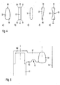
- Fig. 5Fig. 5
- eine Seitenansicht einer weiteren per Rapid-Prototyping erzeugten Form für einen Presskanal, einen Zubringerkanal und einen Press-Hohlraum.a side view of another form generated by rapid prototyping for a press channel, a feeder channel and a press cavity.
- Fig. 6Fig. 6
- Ein Draufsicht auf einen Zubringerkanal aus Wachs mit umlaufender Wulst als AnwachshilfeA top view of a feed channel made of wax with a circumferential bead as a waxing aid
- Fig. 7Fig. 7
- Ein Draufsicht auf einen Zubringerkanal aus Polymermaterial mit SollbruchstelleA top view of a feeder channel made of polymer material with a predetermined breaking point
Die in
In der Ausführungsform gemäß
Es wird einstückig mit dem zugehörigen Zubringerkanal 22 erzeugt, der in besonderer Weise ausgebildet ist. Er ist in einer Nut 24 des Muffeldorns 12 aufgenommen und wird durch den Rapid-Prototyping-Formungsschritt in einer aus
Die aus
Der Zubringerkanal 32 weist Entlastungsvorsprünge 35 und 36 auf, die der Strömungsvergleichmäßigung dienen. Sie können auch von der CAM-Vorrichtung größer gewählt werden, um das Volumen des Positivmodells 34 mit dem Zubringerkanal 32 an das Volumen des Positivmodells 20 mit dem Zubringerkanal 22 anzugleichen und so eine gleichzeitige Fertigstellung zu gewährleisten.The
Es ist bevorzugt, dass die Strömungsfront der erweichten Dentalkeramik die Press-Hohlräume gleichzeitig füllt.It is preferred that the flow front of the softened dental ceramic fills the press cavities at the same time.
Aus
Durch vertikales Verschieben per Rapid-Prototyping lässt sich die Farbigkeit bzw. Helligkeit der Dentalrestaurationen beeinflussen; im Beispielsfall ist es vorgesehen, dass die Zubringerkanäle 22 und 32 über Anschläge 40 an einer vertikal vorgegebenen Position an dem Muffeldorn 12 in den Nuten 24 bzw. 30 sitzen, während es in einer modifizierten Ausgestaltung vorgesehen ist, auch die Relativposition zwischen dem Zubringerkanal 22 bzw. 32 und dem Muffeldorn 12 zu variieren.The color and brightness of the dental restorations can be influenced by vertical shifting using rapid prototyping; in the example it is provided that the
Es ist ersichtlich, dass der Abstand zwischen dem Press-Hohlraum 34 und dem Muffelrand 16 vorgegeben ist; bevorzugt beträgt dieser Abstand mindestens 10mm, auch wenn hier aus zeichnerischen Gründen ein kleinerer Abstand dargestellt ist.It can be seen that the distance between the
Moderne Pressöfen für das Pressen von Dentalkeramiken weisen heutzutage typischerweise eine sogenannte Bodenheizung auf. Diese Heizung heizt den Bereich unterhalb der Muffel und ergänzt eine Ringheizung, die die Muffel ringförmig umgibt und in erster Linie für die Erwärmung des Ofeninnenraums sorgt.Modern pressing furnaces for pressing dental ceramics typically have so-called underfloor heating. This heater heats the area below the muffle and supplements a ring heater that surrounds the muffle in a ring and primarily ensures the heating of the furnace interior.
Vielfach werden jedoch Pressöfen verwendet, die ohne Bodenheizung auskommen. In diesem Fall ist die Ringheizung die einzige Heizung. Dies führt dazu, dass die Muffel von außen nach innen erwärmt wird. Hierdurch entstehen kegelförmige isothermische Korridore, wie sie beispielhaft anhand des Korridors 44 in
Aufgrund der Flexibilität des Rapid-Prototypings kann für einen derartigen Ofen bei der Ausgestaltung des Zubringerkanals 32 eine Optimierung dergestalt vorgenommen werden, dass sich sowohl das Positivmodell 34 als auch der Zubringerkanal 32 in einem isothermen Korridor 44 erstreckt. Nachdem bei dieser Lösung der Strömungsweg im unteren Bereich 46 des Zubringerkanals 32 länger ist als im oberen Bereich 48, erfolgt erfindungsgemäß besonders bevorzugt eine Kompensation durch eine entsprechende Form des Zubringerkanals, beispielsweise die Form gemäß
In dem dargestellten Ausführungsbeispiel gemäß
Aus
Gemäß
Bei dem Querschnittsprofil gemäß des Zubringerkanals gemäß
Bei dem keilförmigen Strömungsquerschnitt gemäß
Die eingeschnürte Form gemäß
Diese Formen lassen sich in beliebiger Weise per Rapid-Prototyping einstückig mit dem Positivmodell 32 erzeugen.These forms can be produced in one piece with the
Gemäß
Der Zubringerkanal 32 weist in diesem Ausführungsbeispiel zudem eine Einschnürung 70 im inzisalen Bereich 46 auf, die dazu führt, dass die Farbverteilung sich zu dunkleren Farben hin verlagert.In this exemplary embodiment, the
Gemäss
Gemäss
Claims (19)
- A device for producing dental ceramic comprising a CAD/CAM device for providing a pressing cavity for producing the dental ceramic, wherein the shape of the dental ceramic to be produced is determinable by a CAD device thereof, based on scan data, and wherein a positive model can be produced by a CAM device thereof, based on which the mold cavity can be produced using a lost mold, characterized in that, by means of the CAM device, distribution and transition between different types of ceramics, i.e. types of ceramics, which differ at least with respect to one parameter concerning the material, appearance, strength or the like, is automatically adjustable, wherein, using the CAM device for adjusting the distribution and the transition, the position, the dimensions and the relative height of a feeder channel (22, 32) between a muffle mandrel (12), which corresponds to the press channel, and the pressing cavity (34), are determinable and are automatically adjustable with respect to the pressing cavity (34) and the muffle mandrel (12), for the production of the dental ceramic, depending on at least one of these parameters.
- The dental ceramic production device according to claim 1, characterized in that, using the CAM device the feeder channel (22, 32) can be produces in the form of a platelet having a length of at least 3 mm, which feeder channel transversely extends from the muffle mandrel (12), which can be used as a press channel during pressing, to the pressing cavity (34) for the dental ceramic.
- The device for producing dental ceramic according to one of the preceding claims, characterized in that, using the CAM device, the angle of incidence and/or the height position between the pressing cavity (34) for the dental ceramic and the feeder channel (22, 32), in particular both in vertical and horizontal direction, are or is determinable, respectively.
- The device for producing dental ceramic according to one of the preceding claims, characterized in that, using the CAM device, both the pressing cavity (34) and the feeder channel (22, 32) can be produced, in particular in one piece and generatively, particularly preferably from wax or from plastics such as polyacrylics by rapid prototyping.
- The device for producing dental ceramic according to one of the preceding claims, characterized in that, using the production device (10), the pressing cavity (34) is adjustable with respect to the feeder channel (22, 32), in the vertical relative position thereof in particular with respect to the vertical center of the feeder channel (22, 32).
- The device for producing dental ceramic according to one of the preceding claims, characterized in that, using the CAM device, orientation of the pressing cavity (34) to be selected is selectable such that the incisal/occlusal side of the dental ceramic of the pressing cavity (34) is positioned facing to the muffle base, and the basal side is positioned facing the muffle mandrel (12).
- The device for producing dental ceramic according to one of the preceding claims, characterized in that a virtual space can be defined using the CAM device, within which the pressing cavity (34) and the feeder channel (22, 32) may extend within the muffle, and visually marks this virtual annular space within the muffle, if necessary during possible user intervention, with respect to the position of the pressing cavity (34) for the dental ceramic.
- The device for producing dental ceramic according to one of the preceding claims, characterized in that, using the CAM device, the longitudinal axes of the pressing cavity (34) for the production of the dental ceramic and the plate-shaped feeder channel (22, 32) can be aligned parallel to each other.
- The device for producing dental ceramic according to one of the preceding claims, characterized in that the vestibular (labial or buccal) sides of the feed channel (22, 32) and the pressing cavity (34) are aligned substantially flush to each other, and in that the horizontal axis of the feed channel (22, 32) passes through the pressing cavity (34), but is deflected relative to its longitudinal axis in the vestibular direction.
- The device for producing dental ceramic according to one of the preceding claims, characterized in that, using the CAM device, the connection point between the feeder channel (22, 32) and the pressing cavity (34) is selectable for the production of the dental ceramic in a proximal peripheral region of the pressing cavity (34).
- The dental ceramic production device according to one of the preceding claims, characterized in that the CAM device is capable of determining the thickness of the feeder channel (22, 32) as a function of the mathematically determined volume of the pressing cavity (34) and, in the case of volumes being below a predetermined threshold value, pressure-reducing spaces may be formed at the feeder channels (22, 32) and/or at the press channel corresponding to the muffle mandrel (12), which spaces relieve the advancing ceramic under isostatic pressure during pressing.
- The device for producing dental ceramic according to one of the preceding claims, characterized in that the pressing cavity (34) comprises a mandrel for forming a stub for the dental ceramic and in that the longitudinal axis of the feeder channel (22, 32) is oriented with respect to the pressing cavity (34) such that it intersects the pressing cavity (34) outside the mandrel and/or in that the longitudinal axis of the feeder channel is formed asymmetrically to the axis of the mandrel.
- The device for producing dental ceramic according to one of the preceding claims, characterized in that the height of a feeder channel (22, 32) corresponds to the height of a pressed blank received in the muffle for designing an especially multicolored dental ceramic, or is at most by 20% less than the height of the blank.
- The device for producing dental ceramic according to one of the preceding claims, characterized in that the muffle mandrel (12) is provided for receiving plate-shaped feeder channels (22, 32), which mandrel (12) especially comprises at least two, preferably four slots for receiving them, the vertical extension of which forms a stop for the vertical alignment of the feeder channels (22; 32).
- The dental ceramic production device according to claim 14, characterized in that the muffle mandrel (12) is provided for receiving and supporting the feeder channels (22, 32) for the press cavities (34) for the production of the dental restoration, and in that the feeder channels (22, 32) are connected to each another by a common hood which is intended to be received on the muffle mandrel (12).
- The device for producing dental ceramic according to one of the preceding claims, characterized in that viscosity differences between the ceramic types may be at least partially compensated by the CAM device using pressure-reducing spaces and/or flow obstacles, which pressure-reducing spaces and/or flow obstacles are arranged in the press channel on one of the feeder channels (22, 32) or on both of the feeder channels or are arranged on all feeder channels.
- The device for producing dental ceramic according to one of the preceding claims, characterized in that the CAM device comprises a feeder channel library, which - optionally with user intervention - allows distribution and transition between the different types of ceramics in dental ceramics based on predetermined distribution and transition patterns between the different types of ceramics in the dental ceramic.
- The device for producing dental ceramic according to one of the preceding claims, characterized in that a circumferential bead (71) is attached to the feeder channel (32), which bead (71) especially is flush with the muffle mandrel (12) after the feeder channel (32) has been inserted into the provided groove (30) on the muffle mandrel (12).
- The device for producing dental ceramic according to one of the preceding claims, characterized in that the feeder channel (22) is made of a polymer material, e.g. polyacrylics, and has a predetermined breaking point (72), in particular at the transition point from the fastening groove (24) to the free feeder channel (22).
Priority Applications (9)
| Application Number | Priority Date | Filing Date | Title |
|---|---|---|---|
| EP14171444.4A EP2952155B1 (en) | 2014-06-06 | 2014-06-06 | Dental ceramic production device |
| US15/306,906 US10588727B2 (en) | 2014-06-06 | 2015-05-22 | Device for producing dental ceramic |
| EP15727331.9A EP3151781B1 (en) | 2014-06-05 | 2015-05-22 | Dental restauration model |
| CA2946354A CA2946354A1 (en) | 2014-06-06 | 2015-05-22 | Device for producing dental ceramic |
| CN201580028401.0A CN106456294B (en) | 2014-06-05 | 2015-05-22 | Dental prosthetic model |
| US15/115,476 US10058405B2 (en) | 2014-06-05 | 2015-05-22 | Dental restoration model |
| CN201580028013.2A CN106413622B (en) | 2014-06-06 | 2015-05-22 | Dental polishing part manufacturing device |
| PCT/EP2015/061410 WO2015185379A1 (en) | 2014-06-05 | 2015-05-22 | Dental restoration model |
| PCT/EP2015/061446 WO2015185381A1 (en) | 2014-06-06 | 2015-05-22 | Device for producing dental ceramic |
Applications Claiming Priority (1)
| Application Number | Priority Date | Filing Date | Title |
|---|---|---|---|
| EP14171444.4A EP2952155B1 (en) | 2014-06-06 | 2014-06-06 | Dental ceramic production device |
Publications (2)
| Publication Number | Publication Date |
|---|---|
| EP2952155A1 EP2952155A1 (en) | 2015-12-09 |
| EP2952155B1 true EP2952155B1 (en) | 2020-07-22 |
Family
ID=50942056
Family Applications (1)
| Application Number | Title | Priority Date | Filing Date |
|---|---|---|---|
| EP14171444.4A Active EP2952155B1 (en) | 2014-06-05 | 2014-06-06 | Dental ceramic production device |
Country Status (5)
| Country | Link |
|---|---|
| US (1) | US10588727B2 (en) |
| EP (1) | EP2952155B1 (en) |
| CN (1) | CN106413622B (en) |
| CA (1) | CA2946354A1 (en) |
| WO (1) | WO2015185381A1 (en) |
Families Citing this family (5)
| Publication number | Priority date | Publication date | Assignee | Title |
|---|---|---|---|---|
| ES2883207T3 (en) * | 2014-06-05 | 2021-12-07 | Ivoclar Vivadent Ag | Procedure for the fabrication of various dental restorations and a dental ceramic production device |
| WO2016023470A1 (en) * | 2014-08-12 | 2016-02-18 | 杭州而然科技有限公司 | Dental all-ceramic restoration and manufacturing method thereof |
| EP3064169B1 (en) * | 2015-03-04 | 2019-04-24 | Ivoclar Vivadent AG | Method of manufacturing dental ceramic workpieces and apparatus for manufacturing dental ceramic workpieces |
| WO2020084533A1 (en) * | 2018-10-25 | 2020-04-30 | 3M Innovative Properties Company | 3d-printed dental restoration precursor with support element and process of production |
| CN112606269B (en) * | 2020-11-26 | 2022-08-09 | 河北凯力华维包装科技有限公司 | Raw material feeding device capable of adjusting feeding mode and used for processing degradable plastics |
Family Cites Families (9)
| Publication number | Priority date | Publication date | Assignee | Title |
|---|---|---|---|---|
| BE1008372A3 (en) | 1994-04-19 | 1996-04-02 | Materialise Nv | METHOD FOR MANUFACTURING A perfected MEDICAL MODEL BASED ON DIGITAL IMAGE INFORMATION OF A BODY. |
| DE59611075D1 (en) | 1995-12-19 | 2004-10-07 | Ivoclar Vivadent Ag | Process for the manufacture of dental crowns and / or dental bridges |
| US6345984B2 (en) | 1998-04-13 | 2002-02-12 | Jeneric/Pentron, Inc. | Prefabricated components for dental appliances |
| DE60219031T2 (en) | 2001-08-31 | 2007-12-13 | Cynovad, Inc., St. Laurent | METHOD FOR THE PRODUCTION OF CASTINGS |
| JP2005059477A (en) | 2003-08-18 | 2005-03-10 | Shiyoufuu:Kk | Apparatus of manufacturing three-dimensional structure |
| WO2008058191A2 (en) * | 2006-11-07 | 2008-05-15 | Geodigm Corporation | Sprue formers |
| DE102006061143A1 (en) * | 2006-12-22 | 2008-07-24 | Aepsilon Rechteverwaltungs Gmbh | Method, computer-readable medium and computer relating to the manufacture of dental prostheses |
| WO2008103024A1 (en) * | 2007-02-23 | 2008-08-28 | Oratio B.V. | Method of manufacturing a multi-layered dental restoration using a sacrificed occlusal build-up layer intermediate |
| US7691497B1 (en) * | 2007-04-13 | 2010-04-06 | Ivoclar Vivadent, Inc. | Pressable overlay material for veneering of zirconia and composites thereof |
-
2014
- 2014-06-06 EP EP14171444.4A patent/EP2952155B1/en active Active
-
2015
- 2015-05-22 US US15/306,906 patent/US10588727B2/en active Active
- 2015-05-22 CA CA2946354A patent/CA2946354A1/en not_active Abandoned
- 2015-05-22 WO PCT/EP2015/061446 patent/WO2015185381A1/en active Application Filing
- 2015-05-22 CN CN201580028013.2A patent/CN106413622B/en active Active
Non-Patent Citations (1)
| Title |
|---|
| None * |
Also Published As
| Publication number | Publication date |
|---|---|
| EP2952155A1 (en) | 2015-12-09 |
| US10588727B2 (en) | 2020-03-17 |
| CN106413622A (en) | 2017-02-15 |
| CN106413622B (en) | 2019-06-04 |
| US20170042647A1 (en) | 2017-02-16 |
| CA2946354A1 (en) | 2015-12-10 |
| WO2015185381A1 (en) | 2015-12-10 |
Similar Documents
| Publication | Publication Date | Title |
|---|---|---|
| EP2862539B1 (en) | Dental positioning device | |
| EP2952155B1 (en) | Dental ceramic production device | |
| EP2952154B1 (en) | Method for producing dental restorations and dental ceramic production device | |
| EP2957252B1 (en) | Method for the production of a three-dimensional true model of the actual position of at least two the teeth of a patient | |
| EP3041434B1 (en) | Dental restoration | |
| EP0781530A2 (en) | Method for manufacturing tooth crowns and/or dental bridges | |
| EP2410939B1 (en) | Gingiva former and method for producing a design of a gingiva former | |
| EP2065012A1 (en) | Method and system for manufacturing dental restoration made of ceramic | |
| EP3612131B1 (en) | Method for producing a dental prosthesis having parallel roots of the prosthetic teeth | |
| WO2015181092A1 (en) | Dental prosthesis production device and dental prosthesis | |
| DE102017113814B4 (en) | Process for the production of a dental prosthesis with a defined adhesive gap | |
| EP3254641B1 (en) | Method for producing an attachment of a radiation curing device, attachment and dental restoration producing device | |
| EP3572035B1 (en) | Dental prosthesis, associated semi-finished product and kit | |
| DE102011004551B4 (en) | Method of making a number of dental restorations | |
| DE10348369A1 (en) | Tooth restoration part | |
| EP3593756B1 (en) | Method for producing a prosthesis or partial prosthesis | |
| EP3496656B1 (en) | Method for producing a prosthesis or partial prosthesis | |
| EP3157460B1 (en) | Prosthesis base and method for integrally bonding at least one artificial tooth to a prosthesis base | |
| WO2015055793A1 (en) | Dental transfer template | |
| EP3151781B1 (en) | Dental restauration model | |
| EP3445274B1 (en) | Dental piece arch and method for producing a dental piece arch | |
| DE19850451C1 (en) | Method of making dental tooth insert involves attached formed cap to tooth using ceramic mass | |
| EP3064169B1 (en) | Method of manufacturing dental ceramic workpieces and apparatus for manufacturing dental ceramic workpieces | |
| WO2016138994A1 (en) | Blank for producing dental replacement parts, said blank having a dentine zone which is embedded in an enamel zone | |
| DE102017117491A1 (en) | Method for producing a prosthesis or partial denture |
Legal Events
| Date | Code | Title | Description |
|---|---|---|---|
| PUAI | Public reference made under article 153(3) epc to a published international application that has entered the european phase |
Free format text: ORIGINAL CODE: 0009012 |
|
| AK | Designated contracting states |
Kind code of ref document: A1 Designated state(s): AL AT BE BG CH CY CZ DE DK EE ES FI FR GB GR HR HU IE IS IT LI LT LU LV MC MK MT NL NO PL PT RO RS SE SI SK SM TR |
|
| AX | Request for extension of the european patent |
Extension state: BA ME |
|
| 17P | Request for examination filed |
Effective date: 20151117 |
|
| RBV | Designated contracting states (corrected) |
Designated state(s): AL AT BE BG CH CY CZ DE DK EE ES FI FR GB GR HR HU IE IS IT LI LT LU LV MC MK MT NL NO PL PT RO RS SE SI SK SM TR |
|
| STAA | Information on the status of an ep patent application or granted ep patent |
Free format text: STATUS: EXAMINATION IS IN PROGRESS |
|
| 17Q | First examination report despatched |
Effective date: 20161214 |
|
| REG | Reference to a national code |
Ref country code: DE Ref legal event code: R079 Ref document number: 502014014486 Country of ref document: DE Free format text: PREVIOUS MAIN CLASS: A61C0013000000 Ipc: A61C0005730000 |
|
| RIC1 | Information provided on ipc code assigned before grant |
Ipc: A61C 13/083 20060101ALI20191213BHEP Ipc: A61C 5/73 20170101AFI20191213BHEP |
|
| GRAP | Despatch of communication of intention to grant a patent |
Free format text: ORIGINAL CODE: EPIDOSNIGR1 |
|
| STAA | Information on the status of an ep patent application or granted ep patent |
Free format text: STATUS: GRANT OF PATENT IS INTENDED |
|
| INTG | Intention to grant announced |
Effective date: 20200207 |
|
| GRAS | Grant fee paid |
Free format text: ORIGINAL CODE: EPIDOSNIGR3 |
|
| GRAA | (expected) grant |
Free format text: ORIGINAL CODE: 0009210 |
|
| STAA | Information on the status of an ep patent application or granted ep patent |
Free format text: STATUS: THE PATENT HAS BEEN GRANTED |
|
| AK | Designated contracting states |
Kind code of ref document: B1 Designated state(s): AL AT BE BG CH CY CZ DE DK EE ES FI FR GB GR HR HU IE IS IT LI LT LU LV MC MK MT NL NO PL PT RO RS SE SI SK SM TR |
|
| REG | Reference to a national code |
Ref country code: GB Ref legal event code: FG4D Free format text: NOT ENGLISH |
|
| REG | Reference to a national code |
Ref country code: CH Ref legal event code: EP |
|
| REG | Reference to a national code |
Ref country code: DE Ref legal event code: R096 Ref document number: 502014014486 Country of ref document: DE |
|
| REG | Reference to a national code |
Ref country code: AT Ref legal event code: REF Ref document number: 1292660 Country of ref document: AT Kind code of ref document: T Effective date: 20200815 |
|
| REG | Reference to a national code |
Ref country code: IE Ref legal event code: FG4D Free format text: LANGUAGE OF EP DOCUMENT: GERMAN |
|
| REG | Reference to a national code |
Ref country code: CH Ref legal event code: NV Representative=s name: KELLER SCHNEIDER PATENT- UND MARKENANWAELTE AG, CH |
|
| REG | Reference to a national code |
Ref country code: SE Ref legal event code: TRGR |
|
| REG | Reference to a national code |
Ref country code: LT Ref legal event code: MG4D |
|
| PG25 | Lapsed in a contracting state [announced via postgrant information from national office to epo] |
Ref country code: NO Free format text: LAPSE BECAUSE OF FAILURE TO SUBMIT A TRANSLATION OF THE DESCRIPTION OR TO PAY THE FEE WITHIN THE PRESCRIBED TIME-LIMIT Effective date: 20201022 Ref country code: FI Free format text: LAPSE BECAUSE OF FAILURE TO SUBMIT A TRANSLATION OF THE DESCRIPTION OR TO PAY THE FEE WITHIN THE PRESCRIBED TIME-LIMIT Effective date: 20200722 Ref country code: GR Free format text: LAPSE BECAUSE OF FAILURE TO SUBMIT A TRANSLATION OF THE DESCRIPTION OR TO PAY THE FEE WITHIN THE PRESCRIBED TIME-LIMIT Effective date: 20201023 Ref country code: LT Free format text: LAPSE BECAUSE OF FAILURE TO SUBMIT A TRANSLATION OF THE DESCRIPTION OR TO PAY THE FEE WITHIN THE PRESCRIBED TIME-LIMIT Effective date: 20200722 Ref country code: HR Free format text: LAPSE BECAUSE OF FAILURE TO SUBMIT A TRANSLATION OF THE DESCRIPTION OR TO PAY THE FEE WITHIN THE PRESCRIBED TIME-LIMIT Effective date: 20200722 Ref country code: PT Free format text: LAPSE BECAUSE OF FAILURE TO SUBMIT A TRANSLATION OF THE DESCRIPTION OR TO PAY THE FEE WITHIN THE PRESCRIBED TIME-LIMIT Effective date: 20201123 Ref country code: BG Free format text: LAPSE BECAUSE OF FAILURE TO SUBMIT A TRANSLATION OF THE DESCRIPTION OR TO PAY THE FEE WITHIN THE PRESCRIBED TIME-LIMIT Effective date: 20201022 Ref country code: ES Free format text: LAPSE BECAUSE OF FAILURE TO SUBMIT A TRANSLATION OF THE DESCRIPTION OR TO PAY THE FEE WITHIN THE PRESCRIBED TIME-LIMIT Effective date: 20200722 |
|
| PG25 | Lapsed in a contracting state [announced via postgrant information from national office to epo] |
Ref country code: LV Free format text: LAPSE BECAUSE OF FAILURE TO SUBMIT A TRANSLATION OF THE DESCRIPTION OR TO PAY THE FEE WITHIN THE PRESCRIBED TIME-LIMIT Effective date: 20200722 Ref country code: PL Free format text: LAPSE BECAUSE OF FAILURE TO SUBMIT A TRANSLATION OF THE DESCRIPTION OR TO PAY THE FEE WITHIN THE PRESCRIBED TIME-LIMIT Effective date: 20200722 Ref country code: RS Free format text: LAPSE BECAUSE OF FAILURE TO SUBMIT A TRANSLATION OF THE DESCRIPTION OR TO PAY THE FEE WITHIN THE PRESCRIBED TIME-LIMIT Effective date: 20200722 Ref country code: IS Free format text: LAPSE BECAUSE OF FAILURE TO SUBMIT A TRANSLATION OF THE DESCRIPTION OR TO PAY THE FEE WITHIN THE PRESCRIBED TIME-LIMIT Effective date: 20201122 |
|
| PG25 | Lapsed in a contracting state [announced via postgrant information from national office to epo] |
Ref country code: NL Free format text: LAPSE BECAUSE OF FAILURE TO SUBMIT A TRANSLATION OF THE DESCRIPTION OR TO PAY THE FEE WITHIN THE PRESCRIBED TIME-LIMIT Effective date: 20200722 |
|
| REG | Reference to a national code |
Ref country code: DE Ref legal event code: R097 Ref document number: 502014014486 Country of ref document: DE |
|
| PG25 | Lapsed in a contracting state [announced via postgrant information from national office to epo] |
Ref country code: CZ Free format text: LAPSE BECAUSE OF FAILURE TO SUBMIT A TRANSLATION OF THE DESCRIPTION OR TO PAY THE FEE WITHIN THE PRESCRIBED TIME-LIMIT Effective date: 20200722 Ref country code: DK Free format text: LAPSE BECAUSE OF FAILURE TO SUBMIT A TRANSLATION OF THE DESCRIPTION OR TO PAY THE FEE WITHIN THE PRESCRIBED TIME-LIMIT Effective date: 20200722 Ref country code: EE Free format text: LAPSE BECAUSE OF FAILURE TO SUBMIT A TRANSLATION OF THE DESCRIPTION OR TO PAY THE FEE WITHIN THE PRESCRIBED TIME-LIMIT Effective date: 20200722 Ref country code: RO Free format text: LAPSE BECAUSE OF FAILURE TO SUBMIT A TRANSLATION OF THE DESCRIPTION OR TO PAY THE FEE WITHIN THE PRESCRIBED TIME-LIMIT Effective date: 20200722 Ref country code: SM Free format text: LAPSE BECAUSE OF FAILURE TO SUBMIT A TRANSLATION OF THE DESCRIPTION OR TO PAY THE FEE WITHIN THE PRESCRIBED TIME-LIMIT Effective date: 20200722 |
|
| PLBE | No opposition filed within time limit |
Free format text: ORIGINAL CODE: 0009261 |
|
| STAA | Information on the status of an ep patent application or granted ep patent |
Free format text: STATUS: NO OPPOSITION FILED WITHIN TIME LIMIT |
|
| PG25 | Lapsed in a contracting state [announced via postgrant information from national office to epo] |
Ref country code: AL Free format text: LAPSE BECAUSE OF FAILURE TO SUBMIT A TRANSLATION OF THE DESCRIPTION OR TO PAY THE FEE WITHIN THE PRESCRIBED TIME-LIMIT Effective date: 20200722 |
|
| 26N | No opposition filed |
Effective date: 20210423 |
|
| PG25 | Lapsed in a contracting state [announced via postgrant information from national office to epo] |
Ref country code: SK Free format text: LAPSE BECAUSE OF FAILURE TO SUBMIT A TRANSLATION OF THE DESCRIPTION OR TO PAY THE FEE WITHIN THE PRESCRIBED TIME-LIMIT Effective date: 20200722 |
|
| PG25 | Lapsed in a contracting state [announced via postgrant information from national office to epo] |
Ref country code: SI Free format text: LAPSE BECAUSE OF FAILURE TO SUBMIT A TRANSLATION OF THE DESCRIPTION OR TO PAY THE FEE WITHIN THE PRESCRIBED TIME-LIMIT Effective date: 20200722 |
|
| REG | Reference to a national code |
Ref country code: NL Ref legal event code: MP Effective date: 20200722 |
|
| PG25 | Lapsed in a contracting state [announced via postgrant information from national office to epo] |
Ref country code: MC Free format text: LAPSE BECAUSE OF FAILURE TO SUBMIT A TRANSLATION OF THE DESCRIPTION OR TO PAY THE FEE WITHIN THE PRESCRIBED TIME-LIMIT Effective date: 20200722 |
|
| REG | Reference to a national code |
Ref country code: BE Ref legal event code: MM Effective date: 20210630 |
|
| PG25 | Lapsed in a contracting state [announced via postgrant information from national office to epo] |
Ref country code: LU Free format text: LAPSE BECAUSE OF NON-PAYMENT OF DUE FEES Effective date: 20210606 |
|
| PG25 | Lapsed in a contracting state [announced via postgrant information from national office to epo] |
Ref country code: IE Free format text: LAPSE BECAUSE OF NON-PAYMENT OF DUE FEES Effective date: 20210606 |
|
| PG25 | Lapsed in a contracting state [announced via postgrant information from national office to epo] |
Ref country code: BE Free format text: LAPSE BECAUSE OF NON-PAYMENT OF DUE FEES Effective date: 20210630 |
|
| PG25 | Lapsed in a contracting state [announced via postgrant information from national office to epo] |
Ref country code: HU Free format text: LAPSE BECAUSE OF FAILURE TO SUBMIT A TRANSLATION OF THE DESCRIPTION OR TO PAY THE FEE WITHIN THE PRESCRIBED TIME-LIMIT; INVALID AB INITIO Effective date: 20140606 |
|
| PG25 | Lapsed in a contracting state [announced via postgrant information from national office to epo] |
Ref country code: CY Free format text: LAPSE BECAUSE OF FAILURE TO SUBMIT A TRANSLATION OF THE DESCRIPTION OR TO PAY THE FEE WITHIN THE PRESCRIBED TIME-LIMIT Effective date: 20200722 |
|
| P01 | Opt-out of the competence of the unified patent court (upc) registered |
Effective date: 20230607 |
|
| PGFP | Annual fee paid to national office [announced via postgrant information from national office to epo] |
Ref country code: IT Payment date: 20230426 Year of fee payment: 10 Ref country code: FR Payment date: 20230508 Year of fee payment: 10 Ref country code: DE Payment date: 20230522 Year of fee payment: 10 |
|
| PGFP | Annual fee paid to national office [announced via postgrant information from national office to epo] |
Ref country code: SE Payment date: 20230509 Year of fee payment: 10 Ref country code: AT Payment date: 20230509 Year of fee payment: 10 |
|
| PGFP | Annual fee paid to national office [announced via postgrant information from national office to epo] |
Ref country code: GB Payment date: 20230508 Year of fee payment: 10 Ref country code: CH Payment date: 20230702 Year of fee payment: 10 |