EP2952154B1 - Method for producing dental restorations and dental ceramic production device - Google Patents
Method for producing dental restorations and dental ceramic production device Download PDFInfo
- Publication number
- EP2952154B1 EP2952154B1 EP14171268.7A EP14171268A EP2952154B1 EP 2952154 B1 EP2952154 B1 EP 2952154B1 EP 14171268 A EP14171268 A EP 14171268A EP 2952154 B1 EP2952154 B1 EP 2952154B1
- Authority
- EP
- European Patent Office
- Prior art keywords
- dental
- feeder
- channel
- dental restoration
- muffle
- Prior art date
- Legal status (The legal status is an assumption and is not a legal conclusion. Google has not performed a legal analysis and makes no representation as to the accuracy of the status listed.)
- Active
Links
Images


Classifications
-
- G—PHYSICS
- G05—CONTROLLING; REGULATING
- G05B—CONTROL OR REGULATING SYSTEMS IN GENERAL; FUNCTIONAL ELEMENTS OF SUCH SYSTEMS; MONITORING OR TESTING ARRANGEMENTS FOR SUCH SYSTEMS OR ELEMENTS
- G05B19/00—Program-control systems
- G05B19/02—Program-control systems electric
- G05B19/18—Numerical control [NC], i.e. automatically operating machines, in particular machine tools, e.g. in a manufacturing environment, so as to execute positioning, movement or co-ordinated operations by means of program data in numerical form
- G05B19/4097—Numerical control [NC], i.e. automatically operating machines, in particular machine tools, e.g. in a manufacturing environment, so as to execute positioning, movement or co-ordinated operations by means of program data in numerical form characterised by using design data to control NC machines, e.g. CAD/CAM
-
- A—HUMAN NECESSITIES
- A61—MEDICAL OR VETERINARY SCIENCE; HYGIENE
- A61C—DENTISTRY; APPARATUS OR METHODS FOR ORAL OR DENTAL HYGIENE
- A61C13/00—Dental prostheses; Making same
- A61C13/0003—Making bridge-work, inlays, implants or the like
- A61C13/0006—Production methods
- A61C13/0019—Production methods using three dimensional printing
-
- A—HUMAN NECESSITIES
- A61—MEDICAL OR VETERINARY SCIENCE; HYGIENE
- A61C—DENTISTRY; APPARATUS OR METHODS FOR ORAL OR DENTAL HYGIENE
- A61C13/00—Dental prostheses; Making same
- A61C13/0003—Making bridge-work, inlays, implants or the like
- A61C13/0004—Computer-assisted sizing or machining of dental prostheses
-
- A—HUMAN NECESSITIES
- A61—MEDICAL OR VETERINARY SCIENCE; HYGIENE
- A61C—DENTISTRY; APPARATUS OR METHODS FOR ORAL OR DENTAL HYGIENE
- A61C13/00—Dental prostheses; Making same
- A61C13/08—Artificial teeth; Making same
- A61C13/083—Porcelain or ceramic teeth
-
- A—HUMAN NECESSITIES
- A61—MEDICAL OR VETERINARY SCIENCE; HYGIENE
- A61C—DENTISTRY; APPARATUS OR METHODS FOR ORAL OR DENTAL HYGIENE
- A61C13/00—Dental prostheses; Making same
- A61C13/0003—Making bridge-work, inlays, implants or the like
- A61C13/0022—Blanks or green, unfinished dental restoration parts
-
- A—HUMAN NECESSITIES
- A61—MEDICAL OR VETERINARY SCIENCE; HYGIENE
- A61C—DENTISTRY; APPARATUS OR METHODS FOR ORAL OR DENTAL HYGIENE
- A61C5/00—Filling or capping teeth
- A61C5/70—Tooth crowns; Making thereof
- A61C5/77—Methods or devices for making crowns
-
- G—PHYSICS
- G05—CONTROLLING; REGULATING
- G05B—CONTROL OR REGULATING SYSTEMS IN GENERAL; FUNCTIONAL ELEMENTS OF SUCH SYSTEMS; MONITORING OR TESTING ARRANGEMENTS FOR SUCH SYSTEMS OR ELEMENTS
- G05B2219/00—Program-control systems
- G05B2219/30—Nc systems
- G05B2219/35—Nc in input of data, input till input file format
- G05B2219/35134—3-D cad-cam
-
- G—PHYSICS
- G05—CONTROLLING; REGULATING
- G05B—CONTROL OR REGULATING SYSTEMS IN GENERAL; FUNCTIONAL ELEMENTS OF SUCH SYSTEMS; MONITORING OR TESTING ARRANGEMENTS FOR SUCH SYSTEMS OR ELEMENTS
- G05B2219/00—Program-control systems
- G05B2219/30—Nc systems
- G05B2219/45—Nc applications
- G05B2219/45167—Dentist, dental manufacture
Definitions
- the invention relates to a method for producing dental restorations according to the preamble of claim 1 and a dental ceramic production device according to the preamble of claim 18.
- a positive model of the dental restoration is first produced in a suitable manner, for example also modeled according to the taste of the dental technician or dentist, namely from wax or another substance that can be burned without leaving any residue, such as a polymer.
- This positive model is then connected to a so-called muffle base via a feeder channel, which consists, for example, as a pin-shaped element made of the same material as the positive model of the dental restoration.
- a feeder channel which consists, for example, as a pin-shaped element made of the same material as the positive model of the dental restoration.
- This muffle base consists of a disc made of plastic from which a peg-shaped projection protrudes, the end face of which is used as the base for the feeder channel.
- a small radius is optionally also created at the transition between the feeder channel and the Dental restoration on the one hand or the end face of the muffle base on the other hand attached, which is usually referred to as flooding.
- a silicone ring is then placed on the disc-shaped muffle base, which has a shoulder, and a self-hardening potting compound is poured into the interior space thus formed.
- This can for example consist of plaster of paris or other suitable materials.
- the silicone ring After curing, the silicone ring is peeled off or rolled off and the muffle base peeled off. Here, the connection between the end face and the feeder channel or the feeder channels is released, while the wax components initially remain in the hardened muffle.
- the muffle is then heated to a temperature that enables residue-free removal of the wax components. This can be done, for example, in a so-called preheating furnace, which has a temperature of 700 ° C ready.
- the muffle with the cavities now remaining instead of the positive model or the cavity remaining instead of the positive model is turned over so that the channel, which corresponded to the pin of the muffle base, is exposed at the top.
- This channel is at the same time the press channel, and a blank made of a material that is suitable for the formation of the dental restorations, for example of a dental ceramic, is introduced into it.
- a press furnace has a press plunger that penetrates the press channel and further heats the blank together with the muffle according to a specified press program, for example to around 1,100 ° C for a silicate or field gap ceramic, or to 1,600 ° C for an oxide ceramic.
- pressure and heating are then controlled in harmony with one another, so that the blank penetrates the cavity or cavities via the feeder channels when it melts, and the dental restoration is created there bubble-free, if possible.
- WO 03/017864 A1 , US 2008/142183 A1 , US 2008/220395 A1 disclose methods and dental ceramic generating devices wherein a feeder canal is to be determined by one skilled in the art.
- US 2008/153069 A1 discloses a method and a dental ceramic production device, wherein a feeder channel perpendicular to a single lost muffle is automatically determined by CAD software.
- the invention is based on the object of providing a method for producing dental restorations and a dental restoration-producing device which enable the production of dental restorations in high quality and very economically, the method and the device being particularly suitable when lithium disilicate is used as the dental ceramic material should.
- a special module of the CAD software is used to generate the positive model of each dental restoration in a virtual space within the muffle and to determine the position according to the special criteria laid down in claim 1.
- the press channel basically forms the trunk of this "tree", and the feed channels form the branches, at the tips of which a dental restoration is usually provided.
- Both each feeder channel and each dental restoration themselves preferably extend with their main axis along an isotherm, which leads to the lowest temperature gradients within the respective cavity for the respective dental restoration during the pressing process.
- a minimum distance between adjacent dental restorations for example 3 mm
- the dental restorations are particularly preferred in newer press ovens that have floor heating for the muffle, through which the isotherms of the muffle run in a different way than with a pure ring heater.
- the pressing process can be optimized even in the case of a plurality of dental restorations produced in parallel.
- the flow resistance of the heated ceramic material that is used to create the dental restorations can be adjusted by dimensioning the respective feeder channel.
- the setting is preferably made in such a way that the dental restorations, that is to say the corresponding cavities in the muffle, are completely filled at the same time.
- a thinner and / or longer feeder channel will accordingly be produced by the module, and conversely, in the case of a multi-unit bridge with a correspondingly large volume, the feeder channel (s) will be made shorter and / or thicker.
- each dental restoration or each cavity or the positive model
- One of the measures of the inventive alignment of each dental restoration is to select the point with the thickest wall thickness of the respective dental restoration as the docking point of the respective feeder channel on the respective dental restoration and then to align the dental restoration so that its longitudinal axis corresponds to the axis of the feeder channel.
- this measure leads to dental restorations that are particularly inexpensive to produce and that allow the positive model to be generated generatively by rapid prototyping, for example by means of stereolithographic processes, but also to be free from bubbles.
- the feeder channels preferably extend obliquely away from the press channel and its axis and extend obliquely through the muffle, since the press channel axis regularly coincides with the muffle mandrel axis.
- the invention is also provided to adapt the inclination in a certain way to the type of heating of the muffle.
- the muffle When the muffle is heated under the floor, the entire possible angular range between a little more than 0 ° and 120 ° or 130 ° in relation to the axis of the muffle or the press channel is available.
- a so-called virtual interior space can be defined by predetermined distance limits, i.e. a predetermined distance from the press channel and a predetermined distance from the outer wall of the muffle, but also upwards and downwards, within which the module contains the dental restorations including the feeder channels has to arrange. This ensures that muffle cracks do not occur due to wall thicknesses that are too small, but also that the boundary conditions with regard to isothermal energy are complied with.
- a field gap ceramic can have a larger isothermal range or paramoi thermal range, that is to say a range of similar temperatures, than a lithium disilicate ceramic.
- These boundary conditions can also be taken into account by the module according to the invention, so that a plane offset with the corresponding compression of the arrangement of the dental restorations in the tangential direction is not only dependent on the floor heating of the muffle, but also on the material.
- the arrangement and also the number of feeder channels to the type and number of dental restorations. If, for example, an eight-unit bridge with, for example, three feeder channels, which end at the thickest points of the respective teeth as a docking point, extends slightly curved, the resulting arch interior can be used to place another dental restoration with the corresponding feeder channel within the virtual interior.
- the alignment of the dental restorations is modified in such a way that they basically continue to lengthen extends the axis of the feeder channel, essentially with the maximum length of the virtual axis through the positive model, but slightly tilted in the direction of the primary flow direction, mostly in the occlusal direction.
- the deflection of the primary flow direction out of the feeder channel can be reduced from 30 ° to 20 ° in this way, so that the dental restoration is arranged tilted by 10 ° with respect to the maximum length of the virtual axis.
- the dental restorations are arranged around the press channel, but at some distance from its end face.
- the feeder channels defined by the module then each extend between the end face and the dental restorations, and the module preferably distributes the dental restorations uniformly in this area at an angle in front of the end face of the press channel. If the dental restorations and feeder channels are connected to one another, they essentially form a cone or truncated cone, with the end face as a truncated surface, and extend very little out of the conical surface, still in the isothermal area.
- the muffle is not limited to a cylindrical muffle - as it is most common; In principle, a muffle which is pear-shaped when viewed from the side or cloverleaf-shaped when viewed from above can also be used in accordance with the invention.
- Such flow transitions are also favorable in terms of flow technology and reduce the counterpressure during pressing to the required minimum during the forming process.
- the module can take into account that the length of passage through the dental restorations is maximized.
- the software creates the shortest vector to the most distant point of the dental restorations from the docking point and maximizes this length for the exact selection of the docking point.
- each dental restoration relative to the respective feeder channel axis is then selected again so that the imaginary axis between the center of the docking point and the most distant point of the respective dental restoration forms a virtual axis that extends it as an extension of the axis of the respective feeder channel.
- This arrangement can also preferably be shifted somewhat in the occlusal / incisal direction, for example by 10 ° or 15 °, in order to minimize the deflection of the flow.
- each dental restoration can also be helpful in determining the angular alignment of this in relation to the respective feeder channel axis;
- Each dental restoration can preferably also be aligned in such a way that the extension of the respective feeder channel axis runs through it.
- the module determines the length of each feeder channel as a function of the total weight.
- the length of each feeder channel is preferably always significantly less than the length of the main direction of extent through the respective dental restoration and is - depending on the size and weight of this - between 30% and about 70% of the length of the main direction of extent.
- the feeder channels can also be stored in a library, and the module can then select which of the feeder channels from the library that is available beforehand is expediently used here.
- an upright cylinder can also be implemented as a milling blank, which can then have a height of 50 mm, for example.
- the module can provide an angular corridor for the implementation of the dental restorations by means of appropriate oven-related specifications, which allows each dental restoration to always be placed within an isothermal corridor.
- the virtual space specified in this respect is also specified in the horizontal direction by a minimum edge distance of, for example, 10 mm from the outer wall of the muffle and also from the press channel, which corresponds to the muffle mandrel.
- the module also takes into account, in particular, the volume of the respective associated dental restorations and thus sets the length and thickness of the respective feeder channel based on this.
- the muffle size can be determined based on the number of dental restorations to be produced, with the standard sizes 100 g, 200 g and 300 g of muffles with corresponding known dimensions being able to be kept ready.
- a feeder channel as a blind channel for only very few dental restorations to be produced. This serves to moderate an abrupt increase in pressure at the end of the press in order to further reduce the risk of a muffle crack.
- the feeder channel base is provided in a standardized manner.
- This can have a projection which is positively engaged with the muffle mandrel and is stored as the zero point of the virtual interior space for the provision of the feeder channels in the feeder channel library.
- the muffle base namely the muffle pin protruding from the disk-shaped base, can have a central recess which positively receives the corresponding projection of the feeder channel base.
- the feeder channel base is in this respect a disk which is provided with a form-fitting element, for example a projection, which can engage with the muffle mandrel, or which enables some other connection.
- an apron can also be provided on the outer circumference of the feeder channel base which surrounds the muffle mandrel.
- the feeder channel or the plurality of feeder channels extend obliquely laterally away from the surface of the feeder channel base.
- the angle of the feeder channel axis is realized according to the above specifications, and the desired edge distances, that is, the distances between the dental restorations on the one hand and the edges the muffle, on the other hand, can be set by choosing the location of the starting point of the feeder channel on the feeder channel base, which is determined according to the specifications.
- each feeder channel is inclined by 45 °, for example, the vertical position of the respective dental restoration can be increased by shifting the starting point of the feeder channel radially inward. As a result, the feeder channel automatically becomes longer - assuming a constant angle.
- the fluidic effects of this extension can, however, in turn be compensated according to the invention by increasing the diameter of the feeder channel.
- each dental restoration viewed in the side view, can accordingly alternately have a greater and a lesser vertical height in order to provide a space-optimized tree of dental restorations.
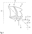
- a positive model 10 of a dental restoration 12 is shown together with its position in space.
- an axis 14 of a feeder channel 16 extends transversely through the positive model 10, starting from a muffle mandrel 18 or press channel 20, more precisely, from its end face 22, at a predetermined angle to an axis 24 of the muffle mandrel 18 or press channel 20, which is 45 ° here.
- the tooth position of the dental restoration or the dental restorations is first recorded.
- the selection of the material for the ceramic to be used also results from the definition of the press concept.
- the dental restoration is determined to match its neighboring teeth in terms of its shape, arrangement in the oral cavity and so on, based on a digital scan of the patient's mouth. From this, the volume of the respective dental restoration is automatically calculated, which also gives the total volume of the dental restorations according to the invention to be produced at the same time.
- the position of the dental restoration in relation to the neighboring teeth is also determined by the CAD software, i.e. in the mesial / distal direction, in the occlusal / cervical direction, in the rotational position around the tooth axis and so on. This also includes the course of the wall thickness of the dental restoration or the positive model.
- the position of the positive model 10 in a virtual space 32 is determined according to the invention based on a special module of the CAD software.
- the total volume is 1.9 cm 3 , so that a muffle of 200 g is sufficient; this includes a corresponding muffle base with a corresponding muffle mandrel 18.
- the positive model has 10 according to Fig. 1 a proportion of 0.4 cm 3 , while a total of 6 further positive models, which are not shown here, extend in the virtual space 32 in a circular or conical manner starting from the muffle mandrel 18 in a corresponding alignment to the alignment of the positive model 10.
- the press concept is intended for a press furnace with ring heating;
- the possible range of the angle 30 is limited to values between, for example, 25 ° and 50 °, and the virtual space 32 is correspondingly smaller compared to a furnace with floor heating.
- the module now generates an optimized arrangement of the positive models 10 in space based on an edge distance to the edge of the muffle of, for example, 10 mm.
- the dental restorations 12 are shifted further towards the outer circumference, but taking into account the edge distances.
- the distance from the end face 22 to the upper end of the virtual space 32 is also limited in the example, here to 16 mm, and 3 mm to 8 mm are specified as the default length for the length of the feeder channel.
- the total length of the dental restoration 12 along the axis 14 and including the length of the feeder channel 16 is as specified per software module in this exemplary embodiment 16 mm, and the minimum distance between the dental restorations 12 is 3 mm.
- angle 30 results in the primary arrangement within a thermal corridor which has a similar temperature range.
- the alignment of the dental restoration 16 in relation to the axis 14 also contributes to this, but also the choice of the docking point 34.
- the angle 30 is determined specifically for the furnace in accordance with the alignment of the isothermal corridor.
- the docking point 34 is selected where the wall thickness of the positive model 10 or the dental restoration 12 is maximum, in the example on a mesiobuccal cusp.
- the alignment of the dental restoration 12 in relation to the axis 14 now takes place in such a way that a virtual axis 36 of the dental restoration, which extends through it from the point of the thickest wall thickness to the most distant point of the dental restoration, that is to say the maximum longitudinal extent of this, also extends the axis 14 of the feeder channel 16 coincides and thus extends as an extension of this.
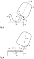
- Fig. 2 in comparison with Fig. 1 As can be seen, this does not mean a coaxial, that is to say exactly coincident arrangements, but an extension, for example with a possible angular deviation of 15 °, in which case reference is made to the following explanation with regard to optimization.
- a feeder channel 16 is now selected from the library of feeder channels, and the overall arrangement of the positive models 10, including the feeder channels 16, is thus determined via the module.
- the overall arrangement of the positive models 10 and feeder channels 16 is now generated by rapid prototyping, which - at least in the present case - has a tree-shaped arrangement.
- the creation of the positive model arrangement takes place in a residue-free removable material such as polyacrylic, or any other suitable polymer that is suitable for rapid prototyping processing and is characterized by particularly good dimensional accuracy.
- the basal surface of the object extends downwards / outwards, based on the muffle mandrel 18.
- the arrangement of the dental restorations 12 or positive models 10 in the top view is based on the cake principle, so that the smallest width of the positive models 10 inside, so the press channel axis 24 is aligned facing.
- the basic alignment of the positive model 10 takes place in the direction of flow, that is, in accordance with the extension of the axis 14.
- the virtual axis 36 of the dental restoration is slightly oblique to the axis 14 of the feeder channel 16. This minimizes the flow deflection so that the main flow of the flowable dental material through the corresponding cavity occurs just below the longitudinal fissure of the molar there, but at least one closer to the occlusal direction than it is from Fig. 1 can be seen.
- the alignment takes place in such a way that the main direction of flow in each case runs through the center of the crown.
- the feeder channel 16 extends from a point of the end face 22 that is located quite far to the outside. It is quite short, only 3 mm in the example, it being understood that a greater length of the feeder channel is also possible if more objects are to be accommodated in the virtual space 32.
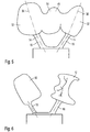
- Fig. 3 it can be seen in what way an anterior crown can extend.
- a blind channel 40 is provided as an additional feed channel 16, which is also created by rapid prototyping - Extends to the feed channel 16 of the dental restoration 10.
- radii 42, 44 are provided on the inlet side of the positive model, which are aerodynamically favorable and also prevent plaster bars, which would otherwise exist there, from breaking off due to the pressure and contaminating the dental restoration.
- a feeder base 46 is formed on the end face 22 of the muffle mandrel 18, which is also produced by rapid prototyping.
- the feeder base 46 establishes the connection between the various feeder channels 16, and at the same time rests against the end face 22 or is anchored there by means of form-fitting means or by means of an adhesive connection.
- the docking point 34 is shown in the arrangement Fig. 3 provided approximately in the middle in the incisal area. This results in a maximized length of the virtual axis 36 such that it extends essentially in the extension of the axis 14.
- stereolithography is preferably used for rapid prototyping. This does not allow any negative layers, so that, for technical reasons, the feeder channel 16 is shifted radially outward - in relation to the axis 24.
- the docking point 34 is hereby compared to Fig. 3 shifted into the approximal area, and the axis 36 extends more obliquely than at Fig. 3 to the axis 14 of the feeder channel 16.
- a correspondingly widened feeder base 46 can be seen, and also the manner in which the material of the feeder base 46 can pass through a recess 48 in the muffle mandrel 18 and reach behind in order to achieve secure anchoring of the feeder base 46.
- Fig. 5 the arrangement of a bridge 49 is shown as a dental restoration.
- the feeder channels 16 extend to the abutment teeth 50 and 52 in the occlusal area thereof, while the bridge member 54 remains free of feeder channels.
- the virtual axes 36 extend through the longest possible extension of the abutment teeth 52 in the extension of the axes 14 of the feeder channels 16. Due to the higher volume of the dental restoration or its weight, only the use of a 200 g muffle and the feeder channels come into consideration here are extended to 5 mm in view of the more voluminous dimensions.
- the realization of a bridge does not exclude that single-tooth dental restorations or their positive models can be formed at the same time and in the same muffle; for example, the dental restoration 12 according to FIG Fig. 6 at a different angular position than the bridge 49 according to Fig. 5 be trained at the same time.
- Fig. 7 a further arrangement of a dental restoration 12, namely a posterior crown, in relation to its feeder channel 16 can be seen.
- Mesiopalatal cusps 58 are selected as the docking point 34 and the CAD software module now rotates the dental restoration 12 or the positive model 10 in such a way that the length L of the virtual axis 36 through the dental restoration 12 is maximized.
- the dental material When the dental material flows in, it is filled from the docking point in the direction of flow essentially with a uniform dental material front. This leads to the basal area 62 being filled with dental material before the likewise basal area 64 which is furthest away from the docking point 34, but which is arranged somewhat more cervically, is filled.
- the dental ceramic front therefore initially experiences a resistance in the area 62, which then gradually increases until the area 64 is also filled.
- This somewhat more even pressure increase is beneficial for two reasons: on the one hand, it allows a pressure reduction just before the actual filling has taken place, in order to avoid an abrupt pressure peak at the end of filling. On the other hand, the risk of muffle cracks due to a pressure surge at the end of filling is reduced, so that the end of filling is evened out.
- FIG. 8 it can be seen in which way a further dental restoration 12 can extend in space.
- a conical isothermal corridor 70 is shown schematically, within which the plurality of dental restorations 12, of which in FIG Fig. 8 one is shown extend.
- the end face 22 is adjacent the lower end 72 of the corridor 70, and the upper end is formed by the upper end of the virtual space 32.
- An envelope 74 extends around each dental restoration 12 and serves to maintain the distance and prevents the dental restoration 12 from being moved too close to adjacent dental restorations. This is in Fig. 8 shown schematically as a rectangle, but in practice the smallest possible space that maintains a distance of 3 mm or 2 mm from the dental restoration 12.
- the docking point 34 is set in the upper third at the thickest point of the inlay.
- the axis 36 is arranged while maximizing the length L as an extension of an axis of the feeder 16, not shown here.
- the direction of flow of the dental ceramic front runs approximately in the middle of the central fissure.
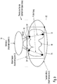
- Fig. 9 a corresponding alignment of a posterior crown 49 using three coordinate systems can be seen by way of example.
- the module calculates an isothermal corridor as a trajectory along which the dental restorations 12 are to extend. At the same time, the possibilities of arranging the dental restorations are limited by the virtual space 32.
- the feeder channels 16 extend at an angle of 45 ° to 60 ° to the horizontal, since a ring heater is used here.
- the third coordinate system is spanned over the envelope 74 of the crown 49, which is again shown here as a rectangle, but is actually an envelope of the dental restoration.
- the direction of flow L of the dental ceramic through the cavities created by the positive model 10 is angled in the extension of the axes of the feeder channels 16, but at an angle of 12 ° with respect to these.
- the spruing takes place in a manner known per se on the incisal surfaces, namely again at the thickest point of each crown, which forms the docking point 34.
- the length of the feeder channels 16 is approximately half the length L of the virtual axis 36. It goes without saying that this value can be adapted to the requirements over a wide range and tends to be somewhat larger for smaller dental restorations and somewhat smaller for larger ones.
Landscapes
- Health & Medical Sciences (AREA)
- Engineering & Computer Science (AREA)
- General Health & Medical Sciences (AREA)
- Oral & Maxillofacial Surgery (AREA)
- Dentistry (AREA)
- Epidemiology (AREA)
- Life Sciences & Earth Sciences (AREA)
- Animal Behavior & Ethology (AREA)
- Public Health (AREA)
- Veterinary Medicine (AREA)
- Manufacturing & Machinery (AREA)
- Chemical & Material Sciences (AREA)
- Ceramic Engineering (AREA)
- Physics & Mathematics (AREA)
- General Physics & Mathematics (AREA)
- Automation & Control Theory (AREA)
- Human Computer Interaction (AREA)
- Dental Tools And Instruments Or Auxiliary Dental Instruments (AREA)
- Dental Prosthetics (AREA)
Description
Die Erfindung betrifft ein Verfahren zur Herstellung von Dentalrestaurationen gemäß dem Oberbegriff von Anspruch 1 sowie eine Dentalkeramik-Erzeugungsvorrichtung gemäß dem Oberbegriff von Anspruch 18.The invention relates to a method for producing dental restorations according to the preamble of
Es ist leit langem bekannt, für die Herstellung von Dentalrestaurationen nach dem Prinzip der verlorenen Form zu arbeiten. Hierzu wird zunächst ein Positivmodell der Dentalrestauration in geeigneter Weise hergestellt, beispielsweise auch nach dem Gusto des Zahntechnikers oder Zahnarztes modelliert, und zwar aus Wachs oder einer anderen rückstandsfrei verbrennbaren Substanz wie einem Polymer.It has long been known to work on the principle of the lost form for the production of dental restorations. For this purpose, a positive model of the dental restoration is first produced in a suitable manner, for example also modeled according to the taste of the dental technician or dentist, namely from wax or another substance that can be burned without leaving any residue, such as a polymer.
Dieses Positivmodell wird dann über einen Zubringerkanal, der beispielsweise als stiftförmiges Element aus dem gleichen Material wie das Positivmodells der Dentalrestauration besteht, mit einer sogenannten Muffelbasis verbunden. Diese Muffelbasis besteht aus einer aus Kunststoff bestehenden Scheibe, aus der ein zapfenförmiger Vorsprung aufragt, dessen Stirnfläche als Basis für den Zubringerkanal verwendet wird.This positive model is then connected to a so-called muffle base via a feeder channel, which consists, for example, as a pin-shaped element made of the same material as the positive model of the dental restoration. This muffle base consists of a disc made of plastic from which a peg-shaped projection protrudes, the end face of which is used as the base for the feeder channel.
Nachdem das Positivmodell zusammen mit dem Zubringerkanal aufgebracht ist, wird gegebenenfalls auch ein kleiner Radius am Übergang zwischen Zubringerkanal und der Dentalrestauration einerseits bzw. der Stirnfläche der Muffelbasis andererseits angebracht, was in der Regel als Verschwemmen bezeichnet wird.After the positive model has been applied together with the feeder channel, a small radius is optionally also created at the transition between the feeder channel and the Dental restoration on the one hand or the end face of the muffle base on the other hand attached, which is usually referred to as flooding.
Auf die scheibenförmige Muffelbasis, die einen Absatz aufweist, wird dann ein Silikonring aufgesteckt und in den so gebildeten Innenraum wird eine selbsthärtende Vergußmasse eingegossen. Diese kann beispielsweise aus Gips oder anderen geeigneten Materialien bestehen.A silicone ring is then placed on the disc-shaped muffle base, which has a shoulder, and a self-hardening potting compound is poured into the interior space thus formed. This can for example consist of plaster of paris or other suitable materials.
Nach dem Aushärten wird der Silikonring abgezogen oder abgerollt und die Muffelbasis abgezogen. Hierbei löst sich die Verbindung zwischen der Stirnfläche und dem Zubringerkanal oder den Zubringerkanälen, während die Wachsbestandteile zunächst noch in der ausgehärteten Muffel verbleiben.After curing, the silicone ring is peeled off or rolled off and the muffle base peeled off. Here, the connection between the end face and the feeder channel or the feeder channels is released, while the wax components initially remain in the hardened muffle.
Die Muffel wird dann erwärmt, und zwar auf eine Temperatur, die eine rückstandsfreie Entfernung der Wachsbestandteile ermöglicht. Dies kann beispielsweise in einem sogenannten Vorwärmofen geschehen, der eine Temperatur von 700°C bereit hält.The muffle is then heated to a temperature that enables residue-free removal of the wax components. This can be done, for example, in a so-called preheating furnace, which has a temperature of 700 ° C ready.
Hieran anschließend wird die Muffel mit den nunmehr anstelle des Positivmodells verbleibenden Hohlräumen oder dem anstelle des Positivmodells verbleibende Hohlraum umgedreht, so dass der Kanal, der dem Zapfen der Muffelbasis entsprach, nach oben freiliegt. Dieser Kanal ist zugleich der Presskanal, und in ihn wird ein Rohling aus einem Material eingebracht, das für die Ausbildung der Dentalrestaurationen geeignet ist, beispielsweise aus einer Dentalkeramik.Subsequently, the muffle with the cavities now remaining instead of the positive model or the cavity remaining instead of the positive model is turned over so that the channel, which corresponded to the pin of the muffle base, is exposed at the top. This channel is at the same time the press channel, and a blank made of a material that is suitable for the formation of the dental restorations, for example of a dental ceramic, is introduced into it.
Ein Pressofen weist einen Pressstempel auf, der in den Presskanal eindringt und nach einem vorgegebenen Pressprogramm den Rohling zusammen mit der Muffel weiter erwärmt, beispielsweise auf größenordnungsmäßig 1.100°C bei einer Silikat- oder Feldspaltkeramik, oder auf 1.600°C bei einer Oxidkeramik.A press furnace has a press plunger that penetrates the press channel and further heats the blank together with the muffle according to a specified press program, for example to around 1,100 ° C for a silicate or field gap ceramic, or to 1,600 ° C for an oxide ceramic.
Nach einem exakt vorgegebenen Pressprogramm werden dann Druck und Erwärmung im Einklang zueinander gesteuert, so dass der Rohling beim Schmelzen über die Zubringerkanäle in den Hohlraum oder die Hohlräume eindringt und dort nach Möglichkeit blasenfrei die Dentalrestauration erzeugt wird.According to a precisely specified pressing program, pressure and heating are then controlled in harmony with one another, so that the blank penetrates the cavity or cavities via the feeder channels when it melts, and the dental restoration is created there bubble-free, if possible.
Das hier beschriebene Verfahren ist seit mindestens 30 Jahren bekannt und wird heute in weitem Umfang eingesetzt.The process described here has been known for at least 30 years and is widely used today.
In neuerer Zeit wird für die Herstellung des Positivmodells vielfach ein Scan des Mundes des Patienten vorgenommen, und es wird über eine CAD-Software die erwünschte Dentalrestauration entworfen und erzeugt.In recent times, a scan of the patient's mouth is often carried out for the production of the positive model, and the desired dental restoration is designed and produced using CAD software.
Es ist auch bereits vorgeschlagen worden, nach dem computergesteuerten Modellieren für die Erzeugung des Positivmodells ein generatives Verfahren einzusetzen, also beispielsweise über Rapid-Prototyping das Positivmodell zu erzeugen. Als beispielhaft sei hierzu auf die
An sich sind derartige Rapid-Prototyping-Verfahren, die auch hinsichtlich der Auflösung für die Dentaltechnik grundsätzlich geeignet sind, beispielsweise die Stereolithografie, bereits ebenfalls seit recht langer Zeit bekannt, nämlich ebenfalls seit den 80er Jahren.Such rapid prototyping methods, which are also fundamentally suitable in terms of resolution for dental technology, for example stereolithography, have also been known for a very long time, namely also since the 1980s.
Im Dentalbereich ist immerhin gemäß der
Trotz der insofern seit recht langer Zeit bekannten und an sich auf der Hand liegenden Vorteile des computergestützen Designs hat sich diese Technik nicht durchgesetzt.In spite of the advantages of computer-aided design that have been known for a long time and are obvious, this technology has not caught on.
Es ist auch bereits vorgeschlagen worden, anstelle der Herstellung des Dentalrestaurationsteils mittels Pressen ein solches über einen Gießvorgang zu erzeugen. Auch diese Technik ist an sich seit langem bekannt.It has also already been proposed, instead of producing the dental restoration part by means of pressing, to produce such a part via a casting process. This technique has also been known per se for a long time.
In neuerer Zeit ist hierzu vorgeschlagen worden, ein Positivmodell per Computerunterstützung zu erzeugen, und zwar generativ, um so die Notwendigkeit des Frässchritts zu vermeiden. Bei diesem Vorschlag hat die Schwierigkeit eine Rolle gespielt, dass beim Fräsen komplexe Innenecken nur sehr schwer zu realisieren sind. Das Gießen eines Formhohlraums in einer Muffel erlaubt es, die Dentalrestauration zentral in der Muffel vorzusehen. An dieser Stelle hat die Muffel in aller Regel einen eher geringen Temperaturgradienten, denn typischerweise wird die Muffel über eine ringförmig diese umgebende Heizung erwärmt, wobei gegebenenfalls noch eine Zusatzheizung von unten vorgesehen ist. Im Außenbereich der Muffel besteht typischerweise ein erheblich größerer Temperaturgradient, gerade bei der angestrebten raschen Erwärmung der Muffel durch den Dentalofen.Recently, it has been proposed to generate a positive model with computer support, namely generatively, in order to avoid the need for the milling step. In this proposal, the difficulty played a role that complex internal corners are very difficult to realize when milling. The casting of a mold cavity in a muffle allows the dental restoration to be provided centrally in the muffle. At this point, the muffle generally has a rather low temperature gradient, because the muffle is typically heated by a heater surrounding it in a ring shape, with additional heating being provided from below if necessary. In the outer area of the muffle there is typically a significantly greater temperature gradient, especially when the muffle is heated rapidly by the dental furnace.
Die so vorgeschlagene Erzeugung der Dentalrestauration hat aber zwei wesentliche Nachteile, so dass nicht verwunderlich ist, dass sich dieser Vorschlag nicht durchgesetzt hat: Zum einen lässt sich bei zentraler Anordnung mit einer Muffel lediglich eine einzige Dentalrestauration erzeugen, was extrem unwirtschaftlich ist. Zum anderen ist die Oberflächenqualität bei gepressten Dentalkeramiken deutlich besser und naturnäher.The production of the dental restoration proposed in this way, however, has two major disadvantages, so that it is not surprising that this proposal has not been implemented: On the one hand, with a central arrangement with a muffle, only a single one can be used Generate dental restoration, which is extremely uneconomical. On the other hand, the surface quality of pressed dental ceramics is significantly better and closer to nature.
Demgegenüber liegt der Erfindung die Aufgabe zugrunde, ein Verfahren zur Herstellung von Dentalrestaurationen sowie eine Dentalrestauration-Erzeugungsvorrichtung bereitzustellen, die die Erstellung von Dentalrestaurationen in hoher Qualität und sehr wirtschaftlich ermöglichen, wobei das Verfahren und die Vorrichtung gerade bei Verwendung von Lithiumdisilikat als Dentalkeramikmaterial besonders geeignet sein soll.In contrast, the invention is based on the object of providing a method for producing dental restorations and a dental restoration-producing device which enable the production of dental restorations in high quality and very economically, the method and the device being particularly suitable when lithium disilicate is used as the dental ceramic material should.
Diese Aufgabe wird erfindungsgemäß durch Anspruch 1 bzw. 18 gelöst. Vorteilhafte Weiterbildungen ergeben sich aus den Unteransprüchen.This object is achieved according to the invention by
Erfindungsgemäß ist es vorgesehen, über ein spezielles Modul der CAD-Software für die Erzeugung des Positivmodells jeder Dentalrestauration diese in einem virtuellen Raum innerhalb der Muffel zu erzeugen und die Position nach den in Anspruch 1 niedergelegten besonderen Kriterien festzulegen. Damit entsteht in überraschend einfacher Weise eine für eine Vielzahl von Zahnformen und Dentalrestaurationsarten geeignete Ausgestaltung von Positivmodellen, die sich über die Zubringerkanäle baumartig erstrecken. Der Presskanal bildet insofern im Grunde den Stamm dieses "Baumes", und die Zubringerkanäle bilden die Äste, an deren Spitze in der Regel je eine Dentalrestauration vorgesehen ist. Bevorzugt erstrecken sich sowohl jeder Zubringerkanal als auch jede Dentalrestauration selbst mit ihrer Hauptachse entlang einer Isotherme, was zu den geringsten Temperaturgradienten innerhalb des jeweiligen Hohlraums für die jeweilige Dentalrestauration beim Pressvorgang führt.According to the invention, a special module of the CAD software is used to generate the positive model of each dental restoration in a virtual space within the muffle and to determine the position according to the special criteria laid down in
Durch die automatische Erzeugung jedes Zubringerkanals und jeder Dentalrestauration lassen sich die bislang auftretenden Fehler, die häufig zu Regressansprüchen gegenüber den Herstellern führten, vollständig vermeiden, und es lässt sich auch die Anzahl der gleichzeitig erzeugten Dentalrestaurationen optimieren.By automatically generating each feeder channel and each dental restoration, the errors that have occurred up to now, which often led to claims for recourse against the manufacturers, can be completely avoided, and the number of dental restorations generated at the same time can also be optimized.
Beispielsweise ist es möglich, einen Minimalabstand zwischen einander benachbarten Dentalrestaurationen zu definieren, beispielsweise 3 mm, und die Dentalrestaurationen durch die insofern per Rapid-Prototyping-erzeugten Positivmodelle im Raum gegeneinander versetzt und auf verschiedenen Ebenen kreisförmig anzuordnen, ohne dass die Gefahr eines Qualitätsverlustes besteht. Die insofern "mehrlagige Anordnung" von Dentalrestaurationen ist besonders bei neueren Pressöfen bevorzugt, die eine Bodenheizung für die Muffel aufweisen, durch welche die Isothermen der Muffel in einer anderen Weise verlaufen als bei einer reinen Ringheizung.For example, it is possible to define a minimum distance between adjacent dental restorations, for example 3 mm, and to arrange the dental restorations in a circle with the positive models generated by rapid prototyping and in a circle on different levels without the risk of loss of quality. The "multi-layer arrangement" of dental restorations is particularly preferred in newer press ovens that have floor heating for the muffle, through which the isotherms of the muffle run in a different way than with a pure ring heater.
Erfindungsgemäß besonders günstig ist es, dass der Pressvorgang gerade auch bei einer Mehrzahl von parallel erstellten Dentalrestaurationen optimiert werden kann. So lässt sich durch Dimensionierung des jeweiligen Zubringerkanals der Strömungswiderstand des erhitzten Keramikmaterials, das für die Erstellung der Dentalrestaurationen verwendet wird, einstellen.According to the invention, it is particularly favorable that the pressing process can be optimized even in the case of a plurality of dental restorations produced in parallel. The flow resistance of the heated ceramic material that is used to create the dental restorations can be adjusted by dimensioning the respective feeder channel.
Die Einstellung erfolgt bevorzugt so, dass die Dentalrestaurationen, also die entsprechenden Hohlräume in der Muffel, gleichzeitig vollständig gefüllt sind. Bei kleineren Volumina der dentalen Restauration wird man dementsprechend einen dünneren und/oder längeren Zubringerkanal von dem Modul erzeugen lassen, und umgekehrt bei einer mehrgliedrigen Brücke mit entsprechend großem Volumen den oder die Zubringerkanäle kürzer und/oder dicker realisieren lassen.The setting is preferably made in such a way that the dental restorations, that is to say the corresponding cavities in the muffle, are completely filled at the same time. In the case of smaller volumes of the dental restoration, a thinner and / or longer feeder channel will accordingly be produced by the module, and conversely, in the case of a multi-unit bridge with a correspondingly large volume, the feeder channel (s) will be made shorter and / or thicker.
Während bislang davon abgeraten wurde, unterschiedliche Dentalrestaurationen in dem gleichen Pressschritt zu erzeugen - insbesondere bei Silikatkeramiken -, ist es erfindungsgemäß ohne weiteres möglich, auch sehr große und sehr kleine Dentalrestaurationen gleichzeitig zu erzeugen, was erfindungsgemäß zur Effizienzsteigerung weiter beiträgt. Gerade Restaurationen aus Lithiumdisilikat mit dem sehr geringen Schrumpfmaß lassen sich so besonders rasch und wirtschaftlich bereitstellen.While it has hitherto been advised against producing different dental restorations in the same pressing step - especially with silicate ceramics - according to the invention it is easily possible to produce very large and very small dental restorations at the same time, which according to the invention further contributes to increasing efficiency. Lithium disilicate restorations with very low shrinkage can be provided particularly quickly and economically in this way.
Zu den Maßnahmen der erfindungsgemäßen Ausrichtung jeder Dentalrestauration (bzw. jedes Hohlraums bzw. des Positivmodells) gehört es, als Andockstelle des jeweiligen Zubringerkanals an der jeweiligen Dentalrestauration die Stelle mit der dicksten Wandstärke der jeweiligen Dentalrestauration auszuwählen und dann die Dentalrestauration so auszurichten, dass ihre Längsachse der Achse des Zubringerkanals entspricht. Diese Maßnahme führt überraschenderweise zu besonders günstig herzustellenden Dentalrestaurationen, die es erlauben, das Positivmodell generativ per Rapid-Prototyping zu erstellen, beispielsweise durch stereolithografische Verfahren, aber auch zu einer Blasenfreiheit.One of the measures of the inventive alignment of each dental restoration (or each cavity or the positive model) is to select the point with the thickest wall thickness of the respective dental restoration as the docking point of the respective feeder channel on the respective dental restoration and then to align the dental restoration so that its longitudinal axis corresponds to the axis of the feeder channel. Surprisingly, this measure leads to dental restorations that are particularly inexpensive to produce and that allow the positive model to be generated generatively by rapid prototyping, for example by means of stereolithographic processes, but also to be free from bubbles.
Beim Vergießen des Positivmodells mittels flüssigem Vergußmaterial wie Gips besteht regelmäßig die Gefahr, dass Hohlräume verbleiben, die nicht mit Vergußmasse gefüllt werden; die insofern bestehende Gefahr ist mit der erfindungsgemäßen Ausrichtung minimiert.When casting the positive model using liquid casting material such as plaster of paris, there is regularly the risk that cavities remain which are not filled with casting compound; the risk that exists in this respect is minimized with the alignment according to the invention.
Andererseits besteht beim Verpressen die Gefahr, dass Blasen in der Keramik verbleiben, die Qualitätseinbußen mit sich bringen; mit der erfindungsgemäßen Schrägstellung gepaart mit dem vorstehend genannten Merkmal ist auch diese Gefahr erfindungsgemäß minimiert.On the other hand, when pressing, there is the risk that bubbles will remain in the ceramic, which will result in a loss of quality; with the inclination according to the invention paired with the aforementioned feature, this risk is also minimized according to the invention.
Bevorzugt erstrecken sich die Zubringerkanäle schräg von dem Presskanal und seiner Achse weg und erstrecken sich insofern schräg durch die Muffel, da regelmäßig die Presskanalachse mit der Muffeldornachse zusammenfällt.The feeder channels preferably extend obliquely away from the press channel and its axis and extend obliquely through the muffle, since the press channel axis regularly coincides with the muffle mandrel axis.
Erfindunsgemäß ist es auch vorgesehen, die Schrägstellung in gewisser Weise an die Art der Beheizung der Muffel anzupassen. Bei Bodenheizung der Muffel steht der gesamt mögliche Winkelbereich zwischen etwas mehr als 0° und 120° oder 130° bezogen auf die Achse der Muffel bzw. des Presskanals, zur Verfügung. Bei Ringheizungen ist es demgegenüber bevorzugt, die Achse in einem Winkel zwischen 40° und 65°, bevorzugt zwischen 45° und 60° zu halten, basierend auf dem engeren Bereich des isothermischen Korridors.According to the invention, it is also provided to adapt the inclination in a certain way to the type of heating of the muffle. When the muffle is heated under the floor, the entire possible angular range between a little more than 0 ° and 120 ° or 130 ° in relation to the axis of the muffle or the press channel is available. In the case of ring heating, on the other hand, it is preferred to keep the axis at an angle between 40 ° and 65 °, preferably between 45 ° and 60 °, based on the narrower area of the isothermal corridor.
Erfindungsgemäß ist es besonders günstig, dass sich durch vorgegebene Abstandsgrenzen, also einen vorgegebenen Abstand zum Presskanal und einen vorgegebenen Abstand zur Außenwand der Muffel, aber auch nach oben und nach unten ein sogenannter virtueller Innenraum festlegen lässt, innerhalb derer das Modul die Dentalrestaurationen einschließlich der Zubringerkanäle anzuordnen hat. Hierdurch ist sichergestellt, dass es nicht durch zu geringe Wandstärken zu Muffelrissen kommt, aber auch, dass die Randbedingungen hinsichtlich der Isothermie eingehalten werden.According to the invention, it is particularly advantageous that a so-called virtual interior space can be defined by predetermined distance limits, i.e. a predetermined distance from the press channel and a predetermined distance from the outer wall of the muffle, but also upwards and downwards, within which the module contains the dental restorations including the feeder channels has to arrange. This ensures that muffle cracks do not occur due to wall thicknesses that are too small, but also that the boundary conditions with regard to isothermal energy are complied with.
In diesem Zusammenhang versteht es sich, dass die mögliche Temperaturabgleichung innerhalb eines als isotherm bezeichneten Bereichs in starkem Maße von dem zu pressenden Keramikmaterial abhängt. Beispielsweise kann eine Feldspaltkeramik einen größeren Isothermiebereich bzw. Paramoi-Thermiebereich, also Bereich ähnlicher Temperaturen, aufweisen als eine Lithiumdisilikatkeramik. Auch diese Randbedingungen lassen sich durch das erfindungsgemäße Modul berücksichtigen, so dass ein Ebenenversatz mit der entsprechenden Verdichtung der Anordnung der Dentalrestaurationen in tangentialer Richtung betrachtet nicht nur bei Bodenheizungen der Muffel, sondern auch materialabhängig ist.In this context, it goes without saying that the possible temperature compensation within a range designated as isothermal depends to a large extent on the ceramic material to be pressed. For example, a field gap ceramic can have a larger isothermal range or paramoi thermal range, that is to say a range of similar temperatures, than a lithium disilicate ceramic. These boundary conditions can also be taken into account by the module according to the invention, so that a plane offset with the corresponding compression of the arrangement of the dental restorations in the tangential direction is not only dependent on the floor heating of the muffle, but also on the material.
Erfindungsgemäß ist es auch günstig, die Anordnung und auch die Anzahl der Zubringerkanäle automatisch an die Art und Anzahl der Dentalrestaurationen anzupassen. Wenn beispielsweise eine achtgliedrige Brücke mit beispielsweise drei Zubringerkanälen, die an den je dicksten Stellen der betreffenden Zähne als Andockstelle enden, sich etwas gebogen erstreckt, kann der so entstehenden Bogeninnenraum für die Platzierung einer weiteren Dentalrestauration mit dem entsprechenden Zubringerkanal innerhalb des virtuellen Innenraums genutzt werden.According to the invention, it is also advantageous to automatically adapt the arrangement and also the number of feeder channels to the type and number of dental restorations. If, for example, an eight-unit bridge with, for example, three feeder channels, which end at the thickest points of the respective teeth as a docking point, extends slightly curved, the resulting arch interior can be used to place another dental restoration with the corresponding feeder channel within the virtual interior.
In vorteilhafter Ausgestaltung ist es vorgesehen, dass die Ausrichtung der Dentalrestaurationen dahingehend modifiziert wird, dass sie sich im Grunde nach wie vor in Verlängerung der Achse des Zubringerkanals erstreckt, und zwar im Wesentlichen mit der maximalen Länge der virtuellen Achse durch das Positivmodell, jedoch etwas abgekippt in Richtung der Primärströmungsrichtung, meist also in Okklusalrichtung. Hierdurch erfolgt eine etwas geringere Strömungsumlenkung an der Andockstelle, was die Neigung zur Blasenbildung weiter reduziert. Beispielsweise kann die Umlenkung der Primärströmungsrichtung aus den Zubringerkanals auf diese Weise von 30° auf 20° reduziert werden, so dass die Dentalrestauration gegenüber der Maximallänge der virtuellen Achse um 10° gekippt angeordnet ist.In an advantageous embodiment, it is provided that the alignment of the dental restorations is modified in such a way that they basically continue to lengthen extends the axis of the feeder channel, essentially with the maximum length of the virtual axis through the positive model, but slightly tilted in the direction of the primary flow direction, mostly in the occlusal direction. This results in a somewhat smaller flow deflection at the docking point, which further reduces the tendency to form bubbles. For example, the deflection of the primary flow direction out of the feeder channel can be reduced from 30 ° to 20 ° in this way, so that the dental restoration is arranged tilted by 10 ° with respect to the maximum length of the virtual axis.
In erfindungsgemäß bevorzugter Weise ist es vorgesehen, dass die Dentalrestaurationen um den Presskanal herum, jedoch von dessen Stirnfläche noch etwas beabstandet, angeordnet sind. Zwischen der Stirnfläche und den Dentalrestaurationen erstrecken sich dann je die von dem Modul festgelegt Zubringerkanäle, und das Modul verteilt die Dentalrestaurationen bevorzugt gleichförmig in diesem Bereich schräg vor der Stirnfläche des Presskanals. Wenn man die Dentalrestaurationen und Zubringerkanäle gedanklich miteinander verbindet, bilden sie insofern im Wesentlichen einen Kegel oder Kegelstumpf, mit der Stirnfläche als Stumpffläche und erstrecken sich recht wenig, noch im Isothermiebereich, aus der Kegelfläche heraus.In a way that is preferred according to the invention, it is provided that the dental restorations are arranged around the press channel, but at some distance from its end face. The feeder channels defined by the module then each extend between the end face and the dental restorations, and the module preferably distributes the dental restorations uniformly in this area at an angle in front of the end face of the press channel. If the dental restorations and feeder channels are connected to one another, they essentially form a cone or truncated cone, with the end face as a truncated surface, and extend very little out of the conical surface, still in the isothermal area.
Eine achsensymentrische Anordnung der Muffel und des Presskanals ist hier erfindungsgemäß bevorzugt und für die Erreichung eines optimalen Pressergebnisses basierend auf der erfindungsgemäßen Ausgestaltung eigentlich unabdingbar. Jedoch ist die Muffel nicht auf eine zylindrische Muffel - wie sie am weitesten verbreitet ist - beschränkt; auch eine in der Seitenansicht birnenförmige oder in der Draufsicht kleeblattförmige Muffel ist im Grunde erfindungsgemäß einsetzbar.An axially symmetrical arrangement of the muffle and the press channel is preferred according to the invention and is actually indispensable for achieving an optimal pressing result based on the configuration according to the invention. However, the muffle is not limited to a cylindrical muffle - as it is most common; In principle, a muffle which is pear-shaped when viewed from the side or cloverleaf-shaped when viewed from above can also be used in accordance with the invention.
Durch die in bevorzugter Ausgestaltung vorgesehenen stetigen Übergänge oder Radien zwischen den Zubringerkanälen und dem Presskanal einerseits, aber auch der Dentalrestaurationen andererseits wird verhindert, dass dort bestehendes Muffelmaterial beim Pressvorgang einem zu hohen Druck ausgesetzt wird und dementsprechend bricht. Derartige Strömungsübergänge sind zudem strömungstechnisch günstig und reduzieren den Gegendruck beim Pressen während der Umformung auf das erforderliche Minimalmaß.The continuous transitions or radii provided in a preferred embodiment between the feeder channels and the press channel on the one hand, but also the dental restorations on the other hand, prevent the muffle material existing there from being subjected to excessive pressure during the pressing process and breaking accordingly. Such flow transitions are also favorable in terms of flow technology and reduce the counterpressure during pressing to the required minimum during the forming process.
Als zusätzlichen Gesichtspunkt für die Ausrichtung der Dentalrestaurationen, nämlich die Wahl der jeweiligen Andockstelle, kann das Modul berücksichtigen, dass die Durchtretungslänge durch die Dentalrestaurationen maximiert wird. Hierzu bildet die Software den kürzesten Vektor zur weitest entfernten Stelle der Dentalrestaurationen von der Andockstelle und maximiert diese Länge für die exakte Wahl der Andockstelle.As an additional aspect for the alignment of the dental restorations, namely the choice of the respective docking point, the module can take into account that the length of passage through the dental restorations is maximized. For this purpose, the software creates the shortest vector to the most distant point of the dental restorations from the docking point and maximizes this length for the exact selection of the docking point.
Die Ausrichtung jeder Dentalrestauration relativ zur jeweilen Zubringerkanalachse wird dann wieder so gewählt, dass die gedachte Achse zwischen dem Mittelpunkt der Andockstelle und der am weitesten entfernte Punkt der jeweiligen Dentalrestauration eine virtuelle Achse bilden, die sie in Verlängerung der Achse des jeweiligen Zubringerkanals erstreckt.The alignment of each dental restoration relative to the respective feeder channel axis is then selected again so that the imaginary axis between the center of the docking point and the most distant point of the respective dental restoration forms a virtual axis that extends it as an extension of the axis of the respective feeder channel.
Auch diese Anordnung kann bevorzugt etwas in okklusaler/inzisaler Richtung verschoben werden, beispielsweise um 10° oder 15°, um die Strömungsumlenkung zu minimieren.This arrangement can also preferably be shifted somewhat in the occlusal / incisal direction, for example by 10 ° or 15 °, in order to minimize the deflection of the flow.
In erfindungsgemäß bevorzugter Weise ist es zudem vorgesehen, offene, also basalnahe Flächen jeder Dentalrestauration radial auswärts bezogen auf die Presskanalachse auzurichten. Diese Lösung ist sowohl hinsichtlich der Vermeidung der Bläschenbildung als auch hinsichtlich der Auswirkung von Temperaturgradienten günstig.In a manner preferred according to the invention, it is also provided that open surfaces, that is to say surfaces close to the basal, of each dental restoration are set up radially outwards in relation to the axis of the press channel. This solution is favorable both in terms of avoiding the formation of bubbles and in terms of the effect of temperature gradients.
In vorteilhafter Ausgestaltung kann auch der Massenschwerpunkt der dicksten Stelle der Wand jeder Dentalrestauration bei der Bestimmung der Winkelausrichtung dieser bezogen auf die jeweilige Zubringerkanalachse hilfreich sein; jede Dentalrestauration lässt sich bevorzugt auch so ausrichten, dass die Verlängerung der jeweiligen Zubringerkanalachse durch diesen verläuft.In an advantageous embodiment, the center of mass of the thickest point of the wall of each dental restoration can also be helpful in determining the angular alignment of this in relation to the respective feeder channel axis; Each dental restoration can preferably also be aligned in such a way that the extension of the respective feeder channel axis runs through it.
In weiterer vorteilhafter Ausgestaltung ist es vorgesehen, dass das Modul die Länge jedes Zubringerkanals in Abhängigkeit von dem Gesamtgewicht festlegt. Hierbei beträgt die Länge jedes Zubringerkanals bevorzugt stets deutlich weniger als die Länge der Haupterstreckungsrichtung durch die jeweilige Dentalrestauration und liegt - in Abhängigkeit von der Größe und dem Gewicht dieser - zwischen 30 % und etwa 70 % der Länge der Haupterstreckungsrichtung.In a further advantageous embodiment, it is provided that the module determines the length of each feeder channel as a function of the total weight. The length of each feeder channel is preferably always significantly less than the length of the main direction of extent through the respective dental restoration and is - depending on the size and weight of this - between 30% and about 70% of the length of the main direction of extent.
Die Zubringerkanäle können auch in einer Bibliothek abgespeichert sein, und das Modul kann dann auswählen, welcher der vorab vorliegenden Zubringerkanäle aus der Bibliothek zweckmäßig hier zum Einsatz kommt.The feeder channels can also be stored in a library, and the module can then select which of the feeder channels from the library that is available beforehand is expediently used here.
Während für die Realisierung des Positivmodells die Erstellung per Rapid-Prototyping bevorzugt ist, beispielsweise per Stereolithografie oder per FDM, ist es bei einfacher gestalteten und weniger komplexen Strukturen auch möglich, das Positivmodell per computergesteuertes Fräsen zu fertigen. Hierbei können an sich bekannte Rohlinge, beispielsweise aus einem Poylmer, Polyacryl oder Wachs, zum Einsatz kommen, die scheibenförmig mit einer Höhe von 20 mm oder 25 mm realisiert sind.While rapid prototyping is preferred for realizing the positive model, for example using stereolithography or FDM, it is also possible to produce the positive model using computer-controlled milling for simpler and less complex structures. In this case, blanks known per se, for example made from a polymer, polyacrylic or wax, can be used, which are realized in the form of discs with a height of 20 mm or 25 mm.
Anstelle dieses Flachzylinders kann auch ein aufrechter Zylinder als Fräsrohling realisiert werden, der dann beispielsweise eine Höhe von 50 mm haben kann.Instead of this flat cylinder, an upright cylinder can also be implemented as a milling blank, which can then have a height of 50 mm, for example.
Erfindungsgemäß besonders günstig ist es, dass durch entsprechende ofenbezogene Vorgabe das Modul einen Winkelkorridor für die Realisierung der Dentalrestaurationen bereitstellen kann, der es erlaubt, jede Dentalrestauration stets innerhalb eines isothermischen Korridors zu platzieren. Der insofern vorgegebenen virtuelle Raum ist in horizontaler Richtung zudem durch einen minimalen Randabstand von beispielsweise 10 mm zur Außenwand der Muffel, und auch zum Presskanal, der dem Muffeldorn entspricht, vorgegeben. Für die genauere Einstellung jedes Zubringerkanals berücksichtigt das Modul insbesondere auch das Volumen der je zugehörigen Dentalrestaurationen und stellt damit Länge und Dicke des jeweiligen Zubringerkanals basierend hierauf ein. Zudem lässt sich die Muffelgröße basierend auf der Anzahl der zu fertigenden Dentalrestaurationen festlegen, wobei die Standardgrößen 100 g, 200 g und 300 g von Muffeln mit entsprechenden bekannten Abmessungen bereitgehalten werden können.According to the invention, it is particularly favorable that the module can provide an angular corridor for the implementation of the dental restorations by means of appropriate oven-related specifications, which allows each dental restoration to always be placed within an isothermal corridor. The virtual space specified in this respect is also specified in the horizontal direction by a minimum edge distance of, for example, 10 mm from the outer wall of the muffle and also from the press channel, which corresponds to the muffle mandrel. For the more precise setting of each feeder channel, the module also takes into account, in particular, the volume of the respective associated dental restorations and thus sets the length and thickness of the respective feeder channel based on this. In addition, the muffle size can be determined based on the number of dental restorations to be produced, with the standard sizes 100 g, 200 g and 300 g of muffles with corresponding known dimensions being able to be kept ready.
In vorteilhafter Ausgestaltung ist es hierbei vorgesehen, bei nur sehr wenigen zu fertigenden Dentalrestaurationen einen Zubringerkanal als Blindkanal zu realisieren. Dieser dient dazu, einen abrupten Druckanstieg beim Pressende abzumildern, um die Gefahr eines Muffelrisses weiter zu reduzieren.In an advantageous embodiment, it is provided here to implement a feeder channel as a blind channel for only very few dental restorations to be produced. This serves to moderate an abrupt increase in pressure at the end of the press in order to further reduce the risk of a muffle crack.
In einer weiteren vorteilhaften Ausgestaltung ist es vorgesehen, die Zubringerkanalbasis standardisiert vorzusehen. Diese kann einen Vorsprung aufweisen, der formschlüssig mit dem Muffeldorn in Eingriff steht und als Nullpunkt des virtuellen Innenraums für die Bereitstellung der Zubringerkanäle in der Zubringerkanal-Bibliothek abgespeichert ist. Beispielsweise kann hierzu die Muffelbasis, nämlich der aus der scheibenförmigen Basis emporragender Muffelzapfen, mittig eine Ausnehmung aufweisen, die formschlüssig den entsprechenden Vorsprung der Zubringerkanalbasis aufnimmt.In a further advantageous embodiment, provision is made for the feeder channel base to be provided in a standardized manner. This can have a projection which is positively engaged with the muffle mandrel and is stored as the zero point of the virtual interior space for the provision of the feeder channels in the feeder channel library. For example, the muffle base, namely the muffle pin protruding from the disk-shaped base, can have a central recess which positively receives the corresponding projection of the feeder channel base.
An der Zubringerkanal-Basis wird dann bevorzugt einer Zubringerkanal oder die Mehrzahl von Zubringerkanälen aufgebaut. Die Zubringerkanal-Basis ist insofern eine Scheibe, die mit einem Formschlusselement, beispielsweise einem Vorsprung versehen ist, der mit dem Muffeldorn in Eingriff stehen kann, oder eine sonstige Verbindung ermöglicht.One feeder channel or the plurality of feeder channels is then preferably built up on the feeder channel base. The feeder channel base is in this respect a disk which is provided with a form-fitting element, for example a projection, which can engage with the muffle mandrel, or which enables some other connection.
Alternativ kann auch eine Schürze am Außenumfang der Zubringerkanal-Basis vorgesehen sein, der den Muffeldorn umschließt.Alternatively, an apron can also be provided on the outer circumference of the feeder channel base which surrounds the muffle mandrel.
Von der Oberfläche der Zubringerkanal-Basis erstreckt sich der Zubringerkanal oder die Mehrzahl von Zubringerkanälen schräg seitlich weg. Der Winkel der Zubringerkanal-Achse wird gemäß den vorstehenden Vorgaben realisiert, und die erwünschten Randabstände, also die Abstände zwischen den Dentalrestaurationen einerseits und den Rändern der Muffel andererseits, lassen sich durch die nach den Vorgaben bestimmte Wahl des Ortes des Ansatzpunktes des Zubringerkanals auf der Zubringerkanal-Basis einstellen.The feeder channel or the plurality of feeder channels extend obliquely laterally away from the surface of the feeder channel base. The angle of the feeder channel axis is realized according to the above specifications, and the desired edge distances, that is, the distances between the dental restorations on the one hand and the edges the muffle, on the other hand, can be set by choosing the location of the starting point of the feeder channel on the feeder channel base, which is determined according to the specifications.
Bei einer Schrägstellung jedes Zubringerkanals von 45° lässt sich beispielsweise die vertikale Position der jeweiligen Dentalrestauration dadurch erhöhen, dass der Ansatzpunkt des Zubringerkanals radial einwärts verlagert wird. Hierdurch wird der Zubringerkanal gleichsam automatisch - konstanten Winkel vorausgesetzt - länger. Die strömungstechnischen Effekte dieser Verlängerung lassen sich aber wiederum durch eine Vergrößerung des Durchmessers des Zubringerkanals erfindungsgemäß kompensieren.If each feeder channel is inclined by 45 °, for example, the vertical position of the respective dental restoration can be increased by shifting the starting point of the feeder channel radially inward. As a result, the feeder channel automatically becomes longer - assuming a constant angle. The fluidic effects of this extension can, however, in turn be compensated according to the invention by increasing the diameter of the feeder channel.
Basierend auf dem hinsichtlich der isothermen Korridore optimierten Zubringerkanalwinkel können dementsprechend erfindungsgemäß jede Dentalrestauration in der Seitenansicht betrachtet abwechselnd eine größere und eine geringere vertikale Höhe aufweisen, um so einen raumoptimierten Baum von Dentalrestaurationen bereitzustellen.Based on the feeder channel angle optimized with regard to the isothermal corridors, according to the invention, each dental restoration, viewed in the side view, can accordingly alternately have a greater and a lesser vertical height in order to provide a space-optimized tree of dental restorations.
Weitere Vorteile, Einzelheiten und Merkmale der Erfindung ergeben sich aus der nachstehend Beschreibung mehrerer Ausführungsbeispiele anhand der Zeichnungen.Further advantages, details and features of the invention emerge from the description below of several exemplary embodiments with reference to the drawings.
Es zeigen:
- Fig. 1
- eine schematische Ansicht eines Positivmodells einer Dentalrestauration, zusammen mit dem bereits automatisch von einem Modul einer CAD-Software erzeugten Zubringerkanal, der von einem Presskanal ausgeht;
- Fig. 2
- eine modifizierte Ausgestaltung des Positivmodells der Dentalrestauration gemäß
Fig. 1 , mit einem anderen Winkel des Zubringerkanals; - Fig. 3
- eine dritte beispielhafte Version einer Dentalrestauration bzw. eines Positivmodells, die unter Verwendung eines erfindungsgemäßen Verfahrens hergestellt wird;
- Fig.4
- eine modifizierte Ausgestaltung der Herstellung gemäß
Fig. 3 ; - Fig. 5
- eine schematische Darstellung eines mit Zubringerkanälen versehenen Positivmodells für die Verwendung in einer erfindungsgemäßen Dentalrestauration-Erzeugungsvorrichtung ;
- Fig. 6
- eine weitere Darstellung eines Positivmodells für die Verwendung in einer erfindungsgemäßen Dentalrestauration-Erzeugungsvorrichtung;
- Fig. 7
- eine schematische Darstellung der Ausrichtung des Positivmodells in einem erfindungsgemäßen Verfahren;
- Fig. 8
- eine schematische Darstellung der Ausrichtung eines weiteren Positivmodells und zusätzlich dessen Lage im virtuellen Raum; und
- Fig. 9
- eine schematische Darstellung eines weiteren Positivmodells und dessen Zubringerkanäle, einschlißelich deren Lage im virtuellen Raum.
- Fig. 1
- a schematic view of a positive model of a dental restoration, together with the feeder channel which is already generated automatically by a module of a CAD software and which emanates from a press channel;
- Fig. 2
- a modified embodiment of the positive model of the dental restoration according to
Fig. 1 , with a different angle of the feeder channel; - Fig. 3
- a third exemplary version of a dental restoration or a positive model which is produced using a method according to the invention;
- Fig. 4
- a modified embodiment of the production according to
Fig. 3 ; - Fig. 5
- a schematic representation of a positive model provided with feeder channels for use in a dental restoration generating device according to the invention;
- Fig. 6
- a further illustration of a positive model for use in a dental restoration generating device according to the invention;
- Fig. 7
- a schematic representation of the alignment of the positive model in a method according to the invention;
- Fig. 8
- a schematic representation of the alignment of a further positive model and its position in virtual space; and
- Fig. 9
- a schematic representation of another positive model and its feeder channels, including their position in virtual space.
In
Anhand dieser Darstellung seien nun die wesentlichen Schritte des erfindungsgemäßen Verfahrens erläutert.The essential steps of the method according to the invention will now be explained on the basis of this illustration.
Für die Realisierung des erfindungsgemäßen Verfahrens wird zunächst die Zahnposition der Dentalrestauration oder der Dentalrestaurationen erfasst. Hierzu gehört die Zahnposition im Mund, also z. B. 21, 22 usw. zu dem die Art und Anzahl der Dentalrestaurationen - also z. B. Brücke, Krone, Inlay, Veneer, Prefacette usw. -, aber auch das Presskonzept. Zu diesem gehört auch das Pressprogramm für das spätere Pressen in dem Pressofen; dieses wird in der erfindungsgemäßen Dentalrestauration-Erzeugungsvorrichtung über einen Menüpunkt ausgewählt. Mit dieser Wahl kann optional festgelegt werden, ob der Dentalofen beispielsweise eine standardmäßige Ringheizung oder eine zusätzliche Bodenheizung der Muffel aufweist, die je andere Winkelvorgaben des Winkels 30 der Achse 14 zur Achse 24 umfassen.To implement the method according to the invention, the tooth position of the dental restoration or the dental restorations is first recorded. This includes the position of the teeth in the mouth, e.g. B. 21, 22, etc. to which the type and number of dental restorations - so z. B. bridge, crown, inlay, veneer, prefacette, etc. - but also the press concept. This also includes the press program for the later pressing in the press furnace; this is selected in the dental restoration generating device according to the invention via a menu item. With this choice, it can optionally be determined whether the dental furnace has, for example, a standard ring heater or an additional floor heater for the muffle, each of which includes different angle specifications of the
Basierend auf diesem Presskonzept wird zudem eine entsprechende Bibliothek von Zubringerkanälen - einschließlich deren möglicher Winkel - angeboten.Based on this press concept, a corresponding library of feeder channels - including their possible angles - is also offered.
Mit der Festlegung des Presskonzepts ergibt sich auch die Materialwahl der zu verwendenden Keramik (beispielsweise Oxid- oder Silikatkeramik).The selection of the material for the ceramic to be used (e.g. oxide or silicate ceramic) also results from the definition of the press concept.
Vor oder gegebenenfalls auch nach diesen Festlegungen wird die Dentalrestauration passend zu ihren Nachbarzähnen in ihrer Form, Anordnung im Mundraum und so weiter festgelegt, basierend auf einem digitalen Scan des Mundes des Patienten. Hieraus wird automatisch das Volumen der jeweiligen Dentalrestauration berechnet, woraus sich auch das Gesamtvolumen der erfindungsgemäßen gleichzeitig zu erzeugenden Dentalrestaurationen ergibt.Before or, if necessary, also after these determinations, the dental restoration is determined to match its neighboring teeth in terms of its shape, arrangement in the oral cavity and so on, based on a digital scan of the patient's mouth. From this, the volume of the respective dental restoration is automatically calculated, which also gives the total volume of the dental restorations according to the invention to be produced at the same time.
Auch die Lage der Dentalrestauration bezogen auf die Nachbarzähne wird von der CAD-Software festgelegt, also in mesial/distaler Richtung, in okklusal/zervikaler Richtung, in der Drehposition um die Zahnachse und so weiter. Hierzu gehört auch der Verlauf der Wandstärke der Dentalrestauration bzw. des Positivmodells.The position of the dental restoration in relation to the neighboring teeth is also determined by the CAD software, i.e. in the mesial / distal direction, in the occlusal / cervical direction, in the rotational position around the tooth axis and so on. This also includes the course of the wall thickness of the dental restoration or the positive model.
Nachdem nach dem Gesamtgewicht die Größe der Muffel festgelegt ist, wird erfindungsgemäß basierend auf einem besonderen Modul der CAD-Software die Lage des Positivmodells 10 in einem virtuellen Raum 32 festgelegt.After the size of the muffle has been determined based on the total weight, the position of the
Im Beispiel 2 sei das Gesamtvolumen 1,9 cm3, so dass eine Muffel von 200 g ausreichend ist; zu dieser gehört eine entsprechende Muffelbasis mit einem entsprechenden Muffeldorn 18.In example 2, the total volume is 1.9 cm 3 , so that a muffle of 200 g is sufficient; this includes a corresponding muffle base with a
Von dem Gesamtgewicht habe das Positivmodell 10 gemäß
Im dargestellten Ausführungsbeispiel ist das Presskonzept für einen Pressofen mit Ringheizung bestimmt; hierdurch ist der mögliche Bereich des Winkels 30 auf Werte zwischen beispielsweise 25° und 50° beschränkt, und der virtuelle Raum 32 dementsprechend gegenüber einem Ofen mit Bodenheizung kleiner.In the illustrated embodiment, the press concept is intended for a press furnace with ring heating; As a result, the possible range of the
Das Modul erzeugt nun basierend auf einem Randabstand zum Rand der Muffel von beispielsweise 10 mm eine optimierte Anordnung der Positivmodelle 10 im Raum. Durch Verlängerung der Zubringerkanäle 16 werden die Dentalrestaurationen 12 weiter zum Außenumfang verlagert, jedoch unter Beachtung der Randabstände. Der Abstand von der Stirnfläche 22 zum oberen Ende des virtuellen Raums 32 ist im Beispielsfall ebenfalls beschränkt, hier auf 16 mm, und als Vorgabelänge für die Länge des Zubringerkanals werden 3 mm bis 8 mm vorgegeben. Die Gesamtlänge der Dentalrestauration 12 entlang der Achse 14 und einschließlich der Länge des Zubringerkanals 16 beträgt gemäß der Vorgabe per Softwaremodul in diesem Ausführungsbeispiel 16 mm, und der Minimalabstand der Dentalrestaurationen 12 zueinander beträgt 3 mm.The module now generates an optimized arrangement of the
Durch die Wahl des Winkels 30 ergibt sich die Primäranordnung innerhalb eines thermischen Korridors, der einen ähnlichen Temperaturbereich aufweist. Hierzu trägt auch die Ausrichtung der Dentalrestauration 16 bezogen auf die Achse 14 bei, aber auch die Wahl der Andockstelle 34. Der Winkel 30 wird entsprechend der Ausrichtung des isothermischen Korridors ofenspezifisch festgelegt.The choice of
In dem dargestellten Ausführungsbeispiel ist die Andockstelle 34 dort gewählt, wo die Wandstärke des Positivmodells 10 bzw. der Dentalrestauration 12 maximal ist, im Beispielsfall an einem mesiobukkalen Höcker. Die Ausrichtung der Dentalrestauration 12 bezogen auf die Achse 14 erfolgt nun so, dass eine virtuelle Achse 36 der Dentalrestauration, die sich durch diese von der Stelle der dicksten Wandstärke bis zur am weitesten entfernten Stelle der Dentalrestauration, also der maximalen Längserstreckung dieser, erstreckt, mit der Achse 14 des Zubringerkanals 16 zusammenfällt und sich insofern in Verlängerung dieser erstreckt. Wie aus
Basierend auf den insofern bestehenden Randbedingungen wird nun ein Zubringerkanal 16 aus der Bibliothek der Zubringerkanäle ausgewählt, und über das Modul wird damit die Gesamtanordnung der Positivmodelle 10 einschließlich der Zubringerkanäle 16 festgelegt.Based on the existing boundary conditions, a
In einem Formungsschritt wird nun per Rapid-Prototyping die Gesamtanordnung der Positivmodelle 10 und Zubringerkanäle 16 erzeugt, die - zumindest im vorliegenden Fall - eine baumförmige Anordnung hat.In a shaping step, the overall arrangement of the
Die Erstellung der Positivmodellanordnung erfolgt in einem rückstandsfrei entfernbaren Material wie Polyacryl, oder aber auch einem beliebigen anderen geeigneten Polymer, das für die Rapid-Prototyping-Bearbeitung geeignet ist und sich durch eine besonders gute Formtreue auszeichnet.The creation of the positive model arrangement takes place in a residue-free removable material such as polyacrylic, or any other suitable polymer that is suitable for rapid prototyping processing and is characterized by particularly good dimensional accuracy.
Bei der Verwendung der Stereolithografie-Technik lässt sich so eine Genauigkeit der Erstellung von beispielsweise 50 µm sicherstellen, die allen Anforderungen entspricht.When using the stereolithography technique, an accuracy of production of, for example, 50 µm can be ensured, which meets all requirements.
Wie aus
Die Grundausrichtung der Positivmodells 10 erfolgt in Fließrichtung, also entsprechend der Verlängerung der Achse 14.The basic alignment of the
Gemäß
Wie aus
Größere Längen der Zubringerkanäle weisen bekanntlich einen größeren Strömungswiderstand aufgrund der bestehenden Wandreibung auf. Um dies zu kompensieren, wird gemäß den Vorgaben der Zubringerkanal-Bibliothek dann der Durchmesser des Zubringerkanals vergrößert.As is known, greater lengths of the feeder channels have a greater flow resistance due to the existing wall friction. To compensate for this, the diameter of the feeder canal is then increased in accordance with the specifications of the feeder channel library.
Während die Positionierung gemäß den
Aus
Aus
Wie aus
Die Andockstelle 34 ist bei der Anordnung gemäß
In diesem Ausführungsbeispiel wird für das Rapid-Prototyping bevorzugt die Stereolithographie verwendet. Diese erlaubt keine Negativschichten, so dass aus technischen Gründen eine Verlagerung des Zubringerkanals 16 radial nach außen - bezogen auf die Achse 24 - erfolgt. Die Andockstelle 34 ist hierdurch im Vergleich zu
Aus
In
Auch hier erstrecken sich die virtuellen Achsen 36 durch die längstmögliche Erstreckung der Pfeilerzähne 52 in der Verlängerung der Achsen 14 der Zubringerkanäle 16. Aufgrund des höheren Volumens der Dentalrestauration bzw. deren Gewicht kommt hier nur die Verwendung einer 200 g Muffel in Betracht, und die Zubringerkanäle sind im Hinblick auf die voluminösere Dimensionierung auf 5 mm verlängert.Here, too, the
Die Realisierung einer Brücke schließt nicht aus, dass gleichzeitig und in der gleichen Muffel Einzelzahn-Dentalrestaurationen bzw. deren Positivmodelle geformt sein können; so kann beispielsweise auch die Dentalrestauration 12 gemäß
Aus
Als Andockstelle 34 werden mesiopalatinale Höcker 58 ausgewählt und das Modul der CAD-Software dreht die Dentalrestauration 12 bzw. das Positivmodell 10 nun so, dass die Länge L der virtuellen Achse 36 durch die Dentalrestauration 12 maximiert wird.
Beim Einströmen des Dentalmaterials erfolgt das Befüllen von der Andockstelle her in Strömungsrichtung im Wesentlichen mit einer gleichmäßigen Dentalmaterialfront. Dies führt dazu, dass der basale Bereich 62 mit Dentalmaterial gefüllt ist, bevor der am weitesten von der Andockstelle 34 entfernte, ebenfalls basale Bereich 64, der jedoch etwas zervikaler angeordnet ist, gefüllt wird.When the dental material flows in, it is filled from the docking point in the direction of flow essentially with a uniform dental material front. This leads to the
Die Dentalkeramikfront erfährt daher zunächst im Bereich 62 einen Widerstand, der dann allmählich zunimmt, bis auch der Bereich 64 gefüllt ist. Diese etwas vergleichmäßigte Druckzunahme ist aus zwei Gründen günstig: zum einen erlaubt sie eine Druckreduktion knapp, bevor die tatsächliche Befüllung stattgefunden hat, um eine abrupte Druckspitze bei Befüllungsende zu vermeiden. Zum anderen ist die Gefahr von Muffelrissen aufgrund eines Druckstoßes bei Füllende reduziert, so dass das Füllende vergleichmäßigt wird.The dental ceramic front therefore initially experiences a resistance in the
Aus
Um jede Dentalrestauration 12 erstreckt sich ein Hüllraum 74, der der Abstandswahrung dient und verhindert, dass die Dentalrestauration 12 zu nahe an benachbarte Dentalrestaurationen gerückt wird. Dieser ist in
Wie aus
Aus
Basierend auf dem Muffeldorn 18, der die Basis des ersten Koordinatensystems bildet, wird von dem Modul ein isothermischer Korridor berechnet, als Trajektoriebahn, an der entlang sich die Dentalrestaurationen 12 erstrecken sollen. Zugleich sind die Anordnungsmöglichkeiten der Dentalrestaurationen durch den virtuellen Raum 32 beschränkt.Based on the
Von dem Muffeldorn 18 ausgehend erstrecken sich die Zubringerkanäle 16 in einem Winkel von 45° bis 60° zur Horizontalen, da hier eine Ringheizung eingesetzt wird.Starting from the
Das dritte Koordinatensystem wird über den Hüllraum 74 der Krone 49 aufgespannt, der wiederum hier als Rechteck dargestellt ist, aber tatsächlich eine Umhüllende der Dentalrestauration ist.The third coordinate system is spanned over the
Die Fließrichtung L der Dentalkeramik durch die von dem Positivmodell 10 geschaffenen Hohlräume ist in der Verlängerung der Achsen der Zubringerkanäle 16, jedoch in einem Winkel von 12° gegenüber diesen abgewinkelt.The direction of flow L of the dental ceramic through the cavities created by the
Bei der Brücke erfolgt die Anstiftung in an sich bekannter Weise an den inzisalen Flächen, und zwar wiederum an der dicksten Stelle jeder Krone, die die Andockstelle 34 bildet.In the case of the bridge, the spruing takes place in a manner known per se on the incisal surfaces, namely again at the thickest point of each crown, which forms the
In dem dargestellten Ausführungsbeispiel beträgt die Länge der Zubringerkanäle 16 etwa die Hälfte der Länge L der virtuellen Achse 36. Es versteht sich, dass dieser Wert in weiten Bereichen an die Erfordernisse anpassbar ist und bei kleineren Dentalrestaurationen tendenziell etwas größer und bei größeren etwas geringer ist.In the exemplary embodiment shown, the length of the
Claims (24)
- A process for the manufacture of several dental restorations,- wherein, based on a scanning result of an oral state, using a CAD software, a dental restauration (12) is designed and produced in a residue-free removable material such as wax or polyacrylic, in a shaping step, as a positive model (10) by ablation or generatively, for example by rapid prototyping,- which positive model (10) is molded and removed via a muffle in a manner known per se, and which muffle is provided with a pressing channel (20) which is connected via a feeder channel (16) to a cavity corresponding to the positive model (10) for the dental restoration (12),wherein the blank introduced into the pressing channel (20) is heated and pressurized so that it will deform and dental material for forming the dental restorations (12) enters and fills the cavity through the feeder channels (16),
wherein- during the molding step or subsequently thereto, based on the dimensions of the muffle in relation to the size and shape of the positive model (10) or positive models (10), at least one of the feeder channels (16) is automatically created by a module of the CAD software for each positive model (10),- wherein the module defines a virtual interior space within the muffle for the arrangement of the dental restorations (12) therein,- wherein the feeder channels (16) are connected to the pressing channel (20) such that they form a tree-like arrangement in which the pressing channel (20) forms the trunk of the tree and the feeder channels (16) form the branches at the top of which branches one of the dental restorations (12) is provided, the respective feeder channel (10) extending at an angle (30) between more than 0° and 130°, in relation to the axis (24) of the pressing channel (20), extending obliquely away therefrom, essentially along an isotherm in the muffle, and wherein the flow resistance of a ceramic material used as a dental material is set by dimensioning the respective feeder channel (16),- wherein the site having the thickest wall thickness of the positive model (10) is selected as a docking site (34) of the respective feeder channel (16) on the corresponding dental restoration (12), and the module aligns the positive model (10) with respect to the respective feeder channel (16) such that it extends in extension of the axis (14) of the respective feeder channel (16),- and the length of a virtual axis (36) through the respective positive model (10) is maximized. - The process according to claim claim 1, wherein the length and thickness of each feeder channel (16) relative to the other feeder channels is adjusted to match the volume of its associated dental restoration (12), and in such a way that during pressing the complete filling of the dental restoration (12) takes place simultaneously, in that feeder channels for larger dental restorations (12) are set to a lower flow resistance and feeder channels for smaller dental restorations (12) are set to a higher flow resistance, and in that in particular the flow resistances of the feeder channels are each selected in proportion to the weight of the associated dental restorations (12).
- The process according to one of the claims 1 or 2, wherein the module, based on the shape of the respective dental restoration (12) and thus of the respective positive model (10), starting from the thickest portion, i.e. the portion having the greatest wall thickness for this, determines a primary flow direction for the dental material as the direction in which the flow cross-section is greatest at a predetermined distance from the thickest portion, and in that the longest virtual axis (36) is defined by the positive model (10) in extension of the respective feeder channel axis according to claim 1, but deviating in the direction of the primary flow direction.
- The process according to one of the preceding claims, wherein the orientation of each dental restoration (12) itself and thus of the respective positive model (10) itself within the muffle is determined by the module such that its greatest longitudinal extent substantially extends along an isotherm.
- The process according to one of the preceding claims, wherein simultaneous manufacture of a plurality of dental restorations (12) is arranged substantially along the envelope of a cone and uniformly distributed around the pressing channel (20) which substantially terminates at the apex of said cone.
- The process according one of the preceding claims, wherein the feeder channels are provided with radii (42, 44) and/or continuous transitions on both the input side, i.e. towards the pressing channel (20), and the output side, i.e. towards the dental restoration (12).
- The process according one of the preceding claims, wherein each feeder channel (16) defined by the module, using its axis (14, 24) extended through the dental restoration (12) determines the orientation of the respective dental restoration (12), and that the orientation of the respective dental restoration (12) is selected such that the passage length of the respective extended feeder channel (16) through the respective dental restoration (12) is maximized.
- The process according one of the preceding claims, wherein one of the dental restorations is formed as a crown or bridge (49) and the basal surface of the crown (49) extends in extension of a pressing channel axis (24) with its open side facing away from the pressing channel (20).
- The process according to claim claims 5 or 6, wherein one of the dental restorations (12) is formed as a prefacette or veneer; and the basal surface of the prefacette or veneer extends in a radially outward direction in relation to a pressing channel axis (24).
- The process according to one of the preceding claims, wherein the alignment of each dental restoration (12) with respect to the respective feeder channel axis through the respective dental restoration (12) extends through the center of mass of the respective dental restoration (12) when the respective feeder channel axis is arranged at the thickest portion of the respective dental restoration (12).
- The process according to one of the preceding claims, wherein the module connects the respective feeder channel (16) off-center with respect to the outer surfaces of the respective dental restoration (12), in particular substantially in extension of a labial or buccal surface.
- The process according to one of the preceding claims, wherein the length of each feeder channel (16) is determined by the module as a function of the size and weight of the respective dental restoration (12), in particular for larger dental restorations (12) such as molars, crowns (49) or maxillary anterior crowns having a length of 30% to 50% of the length of the main extension direction of the dental restoration (12) and for smaller dental restorations (12) such as mandibular anterior crowns having a length of 40% to 65% of the length of the main extension direction of the dental restorations (12).
- The process according to one of the preceding claims, 1 wherein, upon arrangement of a plurality of dental restorations (12) in a muffle, the module sets the feeder channels thereto such that the dental restorations (12) are evenly spaced apart, i.e. in an isothermal corridor, and spanning a polyhedron similar to a cone upon formation of imaginary connecting lines therebetween.
- The process according to one of the preceding claims, wherein the module accesses a feeder channel library indicating different profile designs, lengths, docking sites and angles (30) of feeder channels based on sizes and types of dental restorations (12), and that, based on these values, the module determines or suggests the feeder channels in terms of lengths, diameters and angles (30) thereof.
- The process according one of the preceding claims, wherein the virtual inner space for providing the positioning of the dental restorations (12) within the muffle is muffle size-dependent and enables a placement space of the dental restorations (12) within the muffle such that each dental restoration (12) maintains a distance of at least 2 mm from the muffle, in particular 10 mm, in relation to the outer wall of the muffle and, in the radial inward direction, the height of the virtual inner space is less than in the radial outward direction.
- The process according to one of the preceding claims, wherein the positive model (10) is produced by milling and the milled blank is designed as a cylinder having a cylinder height corresponding to the virtual space (32) of between 15 mm and 50 mm, in particular about 40 mm.
- The process according one of the preceding claims, wherein at least one feeder channel (16) is designed as a blind channel (40), i.e. devoid of dental restoration (12).
- A dental ceramic manufacturing device, comprising a CAD/CAM device for providing a press mold for the manufacture of dental ceramics, wherein the CAD/CAM device has CAD software which determines the shape of the dental restorations (12) therefor based on a scanning result of an oral state, and wherein the CAD/CAM device has a CAM device which determines the configuration of a plurality of dental restorations (12) therefor via a lost muffle, wherein the CAD software comprises a module which automatically determines the angular position and the dimensions of a respective feeder channel (16) between a central pressing channel (20) and a respective cavity for shaping the respective dental restoration (12) within a respective virtual inner space within the muffle, wherein the angle of incidence of the respective dental restoration (12) in relation to the respective feeder channel axis of the associated feeder channel (16) at a docking site (34) of the feeder channel (16) on the respective dental restoration (12) is selected at the thickest part of the respective dental restoration (12), is settable such that the extension of the respective feeder channel axis extends through the greatest possible length of the respective dental restoration (12) starting from the thickest part, in particular based on a preset library of shapes of dental restorations (12) and/or feeder channels, and wherein the respective feeder channel (16) is connected to the central pressing channel (20) such that they form a tree-like arrangement, in which the pressing channel (20) forms the tree trunk and the feeder channels (16) form the branches at the tip of which a dental restoration (12) is provided, and wherein the flow resistance of a ceramic material used as dental material can be adjusted by dimensioning the respective feeder channel (16).
- The dental ceramic manufacturing device according to claim 18, wherein the docking site (34) of the respective dental restoration (12) to the respective feeder channel (16) is selected by the module at the portion at which a ball with the largest possible diameter fits into the respective dental restoration (12), wherein the extension of the axis (14, 24) of the respective feeder channel (16) in particular extends substantially through the center of this ball.
- The dental ceramic manufacturing device according to claims 18 or 19, wherein each dental restoration (12) is determined by the module in the virtual space (32) with regard to its arrangement and orientation such that it has an edge distance both from the outer wall of the muffle and from adjacent dental restorations (12) which does not fall below a predetermined value, which in particular is several millimeters.
- The dental ceramic manufacturing device according to one of the claims 18 to 20, wherein the docking sites (34) of the respective dental restoration (12) to the respective feeder channel (16) in the vertical projection in relation to the muffle is selected such that a narrow site of the respective dental restoration (12) is arranged radially inwards, i.e. adjacent to the pressing channel (20), and a wider site is arranged radially further outwards according to the pie principle.
- The dental ceramic manufacturing device according to one of the claims 18 to 21, wherein each feeder channel (16) and/or the respective dental restoration (12) is provided with a code or an identification at a basal site or at a site which at least is covered which code facilitates the assignment to the respective order and/or the respective patients.
- The dental ceramic manufacturing device according to one of the claims 18 to 22, wherein each dental restoration (12), as viewed in the direction of the pressing channel axis (24), in order to provide a continuous and layered build-up thereof, comprises enveloping surfaces which monotonously rise or at most remain outwardly constant, and in any case are not lowered outwardly, as viewed in each case starting from the docking site (34) of the respective dental restoration (12) in the side view thereof.
- The dental ceramic manufacturing device according to one of the preceding claims, wherein the CAM device uses the front surface (22) of the pressing channel (20) as the zero point of the virtual inner space and polymerizes a feeder channel base directly onto this front surface (22), from which the feeder channels extend away.
Priority Applications (9)
| Application Number | Priority Date | Filing Date | Title |
|---|---|---|---|
| EP14171268.7A EP2952154B1 (en) | 2014-06-05 | 2014-06-05 | Method for producing dental restorations and dental ceramic production device |
| ES14171268T ES2883207T3 (en) | 2014-06-05 | 2014-06-05 | Procedure for the fabrication of various dental restorations and a dental ceramic production device |
| CN201580028401.0A CN106456294B (en) | 2014-06-05 | 2015-05-22 | Dental prosthetic model |
| EP15727331.9A EP3151781B1 (en) | 2014-06-05 | 2015-05-22 | Dental restauration model |
| PCT/EP2015/061410 WO2015185379A1 (en) | 2014-06-05 | 2015-05-22 | Dental restoration model |
| US15/115,476 US10058405B2 (en) | 2014-06-05 | 2015-05-22 | Dental restoration model |
| CA2893365A CA2893365C (en) | 2014-06-05 | 2015-06-02 | Process for manufacturing a dental restoration as well as dental ceramics production device |
| US14/732,547 US10816955B2 (en) | 2014-06-05 | 2015-06-05 | Process and device for manufacturing a dental restoration |
| US17/080,198 US20210041852A1 (en) | 2014-06-05 | 2020-10-26 | Process and Device for Manufacturing a Dental Restoration |
Applications Claiming Priority (1)
| Application Number | Priority Date | Filing Date | Title |
|---|---|---|---|
| EP14171268.7A EP2952154B1 (en) | 2014-06-05 | 2014-06-05 | Method for producing dental restorations and dental ceramic production device |
Publications (2)
| Publication Number | Publication Date |
|---|---|
| EP2952154A1 EP2952154A1 (en) | 2015-12-09 |
| EP2952154B1 true EP2952154B1 (en) | 2021-05-05 |
Family
ID=50927943
Family Applications (1)
| Application Number | Title | Priority Date | Filing Date |
|---|---|---|---|
| EP14171268.7A Active EP2952154B1 (en) | 2014-06-05 | 2014-06-05 | Method for producing dental restorations and dental ceramic production device |
Country Status (4)
| Country | Link |
|---|---|
| US (2) | US10816955B2 (en) |
| EP (1) | EP2952154B1 (en) |
| CA (1) | CA2893365C (en) |
| ES (1) | ES2883207T3 (en) |
Cited By (1)
| Publication number | Priority date | Publication date | Assignee | Title |
|---|---|---|---|---|
| EP4534042A1 (en) * | 2023-10-06 | 2025-04-09 | Herting, Torsten | Manufacturing method for dental prosthetic teeth and pre-forms therefor |
Families Citing this family (13)
| Publication number | Priority date | Publication date | Assignee | Title |
|---|---|---|---|---|
| EP3151781B1 (en) * | 2014-06-05 | 2018-10-17 | Ivoclar Vivadent AG | Dental restauration model |
| CN112245041A (en) | 2014-12-09 | 2021-01-22 | 3M创新有限公司 | Dental restoration moulding technique |
| JP6878436B2 (en) | 2015-12-17 | 2021-05-26 | スリーエム イノベイティブ プロパティズ カンパニー | Mold for dental restoration |
| EP3967261A1 (en) | 2015-12-17 | 2022-03-16 | 3M Innovative Properties Company | Dental restoration molds |
| ES2876419T3 (en) | 2016-04-22 | 2021-11-12 | Ivoclar Vivadent Ag | Fabrication procedure of a dental restoration |
| US11547530B2 (en) | 2016-07-26 | 2023-01-10 | 3M Innovative Properties Company | Dental restoration molds |
| WO2018022617A1 (en) | 2016-07-26 | 2018-02-01 | 3M Innovative Properties Company | Dental restoration molds |
| US11801126B2 (en) | 2017-09-19 | 2023-10-31 | 3M Innovative Properties Company | Dental restoration molds |
| US12502260B2 (en) | 2018-08-10 | 2025-12-23 | Solventum Intellectual Properties Company | Dental restoration molds |
| WO2020084533A1 (en) * | 2018-10-25 | 2020-04-30 | 3M Innovative Properties Company | 3d-printed dental restoration precursor with support element and process of production |
| CN111400934B (en) * | 2020-04-15 | 2023-04-07 | 天华化工机械及自动化研究设计院有限公司 | Method for simulating oxygen content distribution of low-temperature carbonization furnace based on WORKBENCH |
| CN117881362A (en) | 2021-08-30 | 2024-04-12 | 3M创新有限公司 | Digital design of dental matrices with improved custom interproximal contacts |
| US20230390034A1 (en) * | 2022-06-03 | 2023-12-07 | B & D Dental Corporation | Certificate System for Tracking Dental Material as it Becomes a Prosthetic |
Citations (1)
| Publication number | Priority date | Publication date | Assignee | Title |
|---|---|---|---|---|
| US20080153069A1 (en) * | 2006-12-22 | 2008-06-26 | Stephan Holzner | Method, machine-readable medium and computer concerning the manufacture of dental prostheses |
Family Cites Families (39)
| Publication number | Priority date | Publication date | Assignee | Title |
|---|---|---|---|---|
| US4081019A (en) * | 1975-12-11 | 1978-03-28 | The J. M. Ney Company | Synthetic resin preform and sprue assembly and method of making same |
| US4161208A (en) * | 1977-12-05 | 1979-07-17 | Cooper Abraham J | Investment casting apparatus |
| DE3203937C2 (en) * | 1982-02-05 | 1985-10-03 | Luc Dr. 4150 Krefeld Barrut | Method and device for machine restoration or correction of at least one tooth or for machine preparation of at least one tooth for a fixed prosthetic restoration and for machine production of the fixed prosthetic restoration |
| BE1008372A3 (en) | 1994-04-19 | 1996-04-02 | Materialise Nv | METHOD FOR MANUFACTURING A perfected MEDICAL MODEL BASED ON DIGITAL IMAGE INFORMATION OF A BODY. |
| JP3672966B2 (en) * | 1995-04-14 | 2005-07-20 | 株式会社ユニスン | Method and apparatus for creating dental prediction model |
| DE19612699C5 (en) * | 1996-03-29 | 2004-03-04 | Sirona Dental Systems Gmbh | Blank for the production of a dental molding |
| US5823778A (en) * | 1996-06-14 | 1998-10-20 | The United States Of America As Represented By The Secretary Of The Air Force | Imaging method for fabricating dental devices |
| JPH1075963A (en) * | 1996-09-06 | 1998-03-24 | Nikon Corp | Method of designing dental prosthesis model and medium recording program for executing this method |
| US5879158A (en) * | 1997-05-20 | 1999-03-09 | Doyle; Walter A. | Orthodontic bracketing system and method therefor |
| US6303059B1 (en) * | 1999-03-26 | 2001-10-16 | Ivoclar A.G. | Method of controlling an oven |
| US20010023056A1 (en) * | 2000-03-15 | 2001-09-20 | Ivoclar Vivadent Ag | Dental device |
| DE60219031T2 (en) * | 2001-08-31 | 2007-12-13 | Cynovad, Inc., St. Laurent | METHOD FOR THE PRODUCTION OF CASTINGS |
| AT411816B (en) | 2002-07-19 | 2004-06-25 | Mediceram Chirurgische Implant | METHOD FOR PRODUCING A RESISTANT STRUCTURE FROM OXIDE CERAMIC, ESPECIALLY FROM ZIRCONDIOXIDE |
| US7658610B2 (en) * | 2003-02-26 | 2010-02-09 | Align Technology, Inc. | Systems and methods for fabricating a dental template with a 3-D object placement |
| US7600999B2 (en) * | 2003-02-26 | 2009-10-13 | Align Technology, Inc. | Systems and methods for fabricating a dental template |
| US7955159B2 (en) * | 2003-08-07 | 2011-06-07 | Ivoclar Vivadent Ag | Machining of ceramic materials |
| EP1506745A1 (en) * | 2003-08-15 | 2005-02-16 | Jeanette Mörmann | Blank and method for making a dental restoration |
| US7445449B2 (en) * | 2004-02-06 | 2008-11-04 | Robert David Sager | Continuous production crown core/crown making process |
| DE102004014573A1 (en) * | 2004-03-25 | 2005-10-27 | BEGO Bremer Goldschlägerei Wilh. Herbst GmbH & Co. KG | Method for producing a muffle for fine or model casting, method for producing a metallic, ceramic or glass-ceramic cast or pressed object and kit for producing such an object |
| US7236842B2 (en) * | 2004-12-02 | 2007-06-26 | Cadent Ltd. | System and method for manufacturing a dental prosthesis and a dental prosthesis manufactured thereby |
| US20090081613A1 (en) * | 2005-03-24 | 2009-03-26 | Biomed Est. | Implant analog |
| DE102005055526A1 (en) * | 2005-11-22 | 2007-06-06 | BEGO Bremer Goldschlägerei Wilh. Herbst GmbH & Co. KG | Method and system for producing a dental prosthesis |
| EP2117750A2 (en) * | 2006-11-07 | 2009-11-18 | Geodigm Corporation | Sprue formers |
| US20090148816A1 (en) * | 2007-01-11 | 2009-06-11 | Geodigm Corporation | Design of dental appliances |
| US8200462B2 (en) * | 2007-01-11 | 2012-06-12 | Geodigm Corporation | Dental appliances |
| JP5209725B2 (en) * | 2007-09-27 | 2013-06-12 | スリーエム イノベイティブ プロパティズ カンパニー | Method of digitally forming a dental model for manufacturing orthodontic craft instruments |
| DE102007056820A1 (en) * | 2007-11-23 | 2009-06-18 | Sirona Dental Systems Gmbh | Measuring body for an implant and method for creating a 3D measurement recording |
| DE102008017784B4 (en) * | 2008-04-08 | 2014-04-17 | Ivoclar Vivadent Ag | Device for making a muffle |
| US8509932B2 (en) * | 2008-07-17 | 2013-08-13 | Cadent Ltd. | Methods, systems and accessories useful for procedures relating to dental implants |
| US8255071B2 (en) * | 2008-11-13 | 2012-08-28 | Innovative Health Technologies, Llc | Method and system for forming a dental prosthesis |
| CA2690407C (en) * | 2009-01-16 | 2016-12-20 | Michel Poirier | Dental prosthesis system |
| JP2012520694A (en) * | 2009-03-20 | 2012-09-10 | 3シェイプ アー/エス | Systems and methods for effective planning, visualization, and optimization of dental restorations |
| US8753114B2 (en) * | 2010-02-26 | 2014-06-17 | William C. Vuillemot | Method for dental restoration and related kit |
| DE102010064142B4 (en) * | 2010-12-23 | 2019-06-13 | BEGO Bremer Goldschlägerei Wilh. Herbst GmbH & Co. KG | Investment material for use in a method of manufacturing a dental restoration by CAD-Cast method |
| EP2551621B1 (en) * | 2011-07-25 | 2017-10-04 | Ivoclar Vivadent AG | Dental oven |
| US20150173864A1 (en) * | 2012-07-12 | 2015-06-25 | Pomodent Dental, Ltd | Abutment assembly for dental implants |
| US10064709B2 (en) * | 2013-02-15 | 2018-09-04 | Jean J. Elnajjar | Separable segmented casting ring for making investment molds |
| EP2952155B1 (en) * | 2014-06-06 | 2020-07-22 | Ivoclar Vivadent AG | Dental ceramic production device |
| DE102015108178A1 (en) * | 2015-05-22 | 2016-11-24 | Degudent Gmbh | Method for producing a dental structure and dental structure |
-
2014
- 2014-06-05 EP EP14171268.7A patent/EP2952154B1/en active Active
- 2014-06-05 ES ES14171268T patent/ES2883207T3/en active Active
-
2015
- 2015-06-02 CA CA2893365A patent/CA2893365C/en active Active
- 2015-06-05 US US14/732,547 patent/US10816955B2/en active Active
-
2020
- 2020-10-26 US US17/080,198 patent/US20210041852A1/en active Pending
Patent Citations (1)
| Publication number | Priority date | Publication date | Assignee | Title |
|---|---|---|---|---|
| US20080153069A1 (en) * | 2006-12-22 | 2008-06-26 | Stephan Holzner | Method, machine-readable medium and computer concerning the manufacture of dental prostheses |
Cited By (2)
| Publication number | Priority date | Publication date | Assignee | Title |
|---|---|---|---|---|
| EP4534042A1 (en) * | 2023-10-06 | 2025-04-09 | Herting, Torsten | Manufacturing method for dental prosthetic teeth and pre-forms therefor |
| WO2025073773A1 (en) * | 2023-10-06 | 2025-04-10 | Herting Torsten | Prosthetic tooth blanks and dental prosthetic production method |
Also Published As
| Publication number | Publication date |
|---|---|
| EP2952154A1 (en) | 2015-12-09 |
| CA2893365C (en) | 2022-06-14 |
| CA2893365A1 (en) | 2015-12-05 |
| US10816955B2 (en) | 2020-10-27 |
| ES2883207T3 (en) | 2021-12-07 |
| US20210041852A1 (en) | 2021-02-11 |
| US20160089220A1 (en) | 2016-03-31 |
Similar Documents
| Publication | Publication Date | Title |
|---|---|---|
| EP2952154B1 (en) | Method for producing dental restorations and dental ceramic production device | |
| EP2862540B1 (en) | Dental positioning device | |
| EP3649983B1 (en) | Dental prosthesis production method | |
| EP2410939B1 (en) | Gingiva former and method for producing a design of a gingiva former | |
| WO1999047065A1 (en) | Dental crowns and/or dental bridges | |
| EP3612131B1 (en) | Method for producing a dental prosthesis having parallel roots of the prosthetic teeth | |
| DE102011119839B4 (en) | Production of superstructures on a SLM system with subsequent milling of the connection geometry | |
| DE102017113814B4 (en) | Process for the production of a dental prosthesis with a defined adhesive gap | |
| EP2952155B1 (en) | Dental ceramic production device | |
| WO2015055790A1 (en) | Dental transfer template | |
| EP4326187B1 (en) | Blank for dental prosthesis and method for its manufacture, use of the blank, and method for manufacturing a dental restoration from the blank | |
| EP0806932B1 (en) | Tooth restoration and prosthesis component made from ceramic material and a method of manufacturing the same. | |
| DE102015106424A1 (en) | Process for producing dentures with a plastic core | |
| EP3157460B1 (en) | Prosthesis base and method for integrally bonding at least one artificial tooth to a prosthesis base | |
| WO2015055793A1 (en) | Dental transfer template | |
| EP3445274B1 (en) | Dental piece arch and method for producing a dental piece arch | |
| EP3151781B1 (en) | Dental restauration model | |
| EP3705078B1 (en) | Method for producing an individual impression tray | |
| EP3064169B1 (en) | Method of manufacturing dental ceramic workpieces and apparatus for manufacturing dental ceramic workpieces | |
| WO2022238049A1 (en) | Method and device for producing a dental prosthesis | |
| EP0943295A1 (en) | Method for the manufactoring of tooth crowns and/or dental bridges | |
| WO2020182816A1 (en) | Blank for producing a dental restoration and method for producing the blank | |
| EP2664296A2 (en) | Method for producing a dental prosthesis |
Legal Events
| Date | Code | Title | Description |
|---|---|---|---|
| PUAI | Public reference made under article 153(3) epc to a published international application that has entered the european phase |
Free format text: ORIGINAL CODE: 0009012 |
|
| AK | Designated contracting states |
Kind code of ref document: A1 Designated state(s): AL AT BE BG CH CY CZ DE DK EE ES FI FR GB GR HR HU IE IS IT LI LT LU LV MC MK MT NL NO PL PT RO RS SE SI SK SM TR |
|
| AX | Request for extension of the european patent |
Extension state: BA ME |
|
| 17P | Request for examination filed |
Effective date: 20160404 |
|
| RBV | Designated contracting states (corrected) |
Designated state(s): AL AT BE BG CH CY CZ DE DK EE ES FI FR GB GR HR HU IE IS IT LI LT LU LV MC MK MT NL NO PL PT RO RS SE SI SK SM TR |
|
| STAA | Information on the status of an ep patent application or granted ep patent |
Free format text: STATUS: EXAMINATION IS IN PROGRESS |
|
| 17Q | First examination report despatched |
Effective date: 20161215 |
|
| RIC1 | Information provided on ipc code assigned before grant |
Ipc: A61C 13/083 20060101ALI20200402BHEP Ipc: A61C 5/77 20170101ALI20200402BHEP Ipc: A61C 13/00 20060101AFI20200402BHEP |
|
| GRAP | Despatch of communication of intention to grant a patent |
Free format text: ORIGINAL CODE: EPIDOSNIGR1 |
|
| STAA | Information on the status of an ep patent application or granted ep patent |
Free format text: STATUS: GRANT OF PATENT IS INTENDED |
|
| INTG | Intention to grant announced |
Effective date: 20200917 |
|
| GRAS | Grant fee paid |
Free format text: ORIGINAL CODE: EPIDOSNIGR3 |
|
| RIN1 | Information on inventor provided before grant (corrected) |
Inventor name: EBERT, JOERG Inventor name: VOIGT, OLIVER Inventor name: SPECHT, TOBIAS Inventor name: GRUENDENFELDER, ROBERT |
|
| GRAA | (expected) grant |
Free format text: ORIGINAL CODE: 0009210 |
|
| STAA | Information on the status of an ep patent application or granted ep patent |
Free format text: STATUS: THE PATENT HAS BEEN GRANTED |
|
| AK | Designated contracting states |
Kind code of ref document: B1 Designated state(s): AL AT BE BG CH CY CZ DE DK EE ES FI FR GB GR HR HU IE IS IT LI LT LU LV MC MK MT NL NO PL PT RO RS SE SI SK SM TR |
|
| REG | Reference to a national code |
Ref country code: GB Ref legal event code: FG4D Free format text: NOT ENGLISH |
|
| REG | Reference to a national code |
Ref country code: CH Ref legal event code: EP |
|
| REG | Reference to a national code |
Ref country code: AT Ref legal event code: REF Ref document number: 1388847 Country of ref document: AT Kind code of ref document: T Effective date: 20210515 |
|
| REG | Reference to a national code |
Ref country code: DE Ref legal event code: R096 Ref document number: 502014015538 Country of ref document: DE |
|
| REG | Reference to a national code |
Ref country code: IE Ref legal event code: FG4D Free format text: LANGUAGE OF EP DOCUMENT: GERMAN |
|
| REG | Reference to a national code |
Ref country code: NL Ref legal event code: FP |
|
| REG | Reference to a national code |
Ref country code: LT Ref legal event code: MG9D |
|
| PG25 | Lapsed in a contracting state [announced via postgrant information from national office to epo] |
Ref country code: HR Free format text: LAPSE BECAUSE OF FAILURE TO SUBMIT A TRANSLATION OF THE DESCRIPTION OR TO PAY THE FEE WITHIN THE PRESCRIBED TIME-LIMIT Effective date: 20210505 Ref country code: LT Free format text: LAPSE BECAUSE OF FAILURE TO SUBMIT A TRANSLATION OF THE DESCRIPTION OR TO PAY THE FEE WITHIN THE PRESCRIBED TIME-LIMIT Effective date: 20210505 Ref country code: FI Free format text: LAPSE BECAUSE OF FAILURE TO SUBMIT A TRANSLATION OF THE DESCRIPTION OR TO PAY THE FEE WITHIN THE PRESCRIBED TIME-LIMIT Effective date: 20210505 Ref country code: BG Free format text: LAPSE BECAUSE OF FAILURE TO SUBMIT A TRANSLATION OF THE DESCRIPTION OR TO PAY THE FEE WITHIN THE PRESCRIBED TIME-LIMIT Effective date: 20210805 |
|
| PG25 | Lapsed in a contracting state [announced via postgrant information from national office to epo] |
Ref country code: IS Free format text: LAPSE BECAUSE OF FAILURE TO SUBMIT A TRANSLATION OF THE DESCRIPTION OR TO PAY THE FEE WITHIN THE PRESCRIBED TIME-LIMIT Effective date: 20210905 Ref country code: GR Free format text: LAPSE BECAUSE OF FAILURE TO SUBMIT A TRANSLATION OF THE DESCRIPTION OR TO PAY THE FEE WITHIN THE PRESCRIBED TIME-LIMIT Effective date: 20210806 Ref country code: LV Free format text: LAPSE BECAUSE OF FAILURE TO SUBMIT A TRANSLATION OF THE DESCRIPTION OR TO PAY THE FEE WITHIN THE PRESCRIBED TIME-LIMIT Effective date: 20210505 Ref country code: NO Free format text: LAPSE BECAUSE OF FAILURE TO SUBMIT A TRANSLATION OF THE DESCRIPTION OR TO PAY THE FEE WITHIN THE PRESCRIBED TIME-LIMIT Effective date: 20210805 Ref country code: PT Free format text: LAPSE BECAUSE OF FAILURE TO SUBMIT A TRANSLATION OF THE DESCRIPTION OR TO PAY THE FEE WITHIN THE PRESCRIBED TIME-LIMIT Effective date: 20210906 Ref country code: PL Free format text: LAPSE BECAUSE OF FAILURE TO SUBMIT A TRANSLATION OF THE DESCRIPTION OR TO PAY THE FEE WITHIN THE PRESCRIBED TIME-LIMIT Effective date: 20210505 Ref country code: SE Free format text: LAPSE BECAUSE OF FAILURE TO SUBMIT A TRANSLATION OF THE DESCRIPTION OR TO PAY THE FEE WITHIN THE PRESCRIBED TIME-LIMIT Effective date: 20210505 Ref country code: RS Free format text: LAPSE BECAUSE OF FAILURE TO SUBMIT A TRANSLATION OF THE DESCRIPTION OR TO PAY THE FEE WITHIN THE PRESCRIBED TIME-LIMIT Effective date: 20210505 |
|
| REG | Reference to a national code |
Ref country code: ES Ref legal event code: FG2A Ref document number: 2883207 Country of ref document: ES Kind code of ref document: T3 Effective date: 20211207 |
|
| PG25 | Lapsed in a contracting state [announced via postgrant information from national office to epo] |
Ref country code: RO Free format text: LAPSE BECAUSE OF FAILURE TO SUBMIT A TRANSLATION OF THE DESCRIPTION OR TO PAY THE FEE WITHIN THE PRESCRIBED TIME-LIMIT Effective date: 20210505 Ref country code: SK Free format text: LAPSE BECAUSE OF FAILURE TO SUBMIT A TRANSLATION OF THE DESCRIPTION OR TO PAY THE FEE WITHIN THE PRESCRIBED TIME-LIMIT Effective date: 20210505 Ref country code: SM Free format text: LAPSE BECAUSE OF FAILURE TO SUBMIT A TRANSLATION OF THE DESCRIPTION OR TO PAY THE FEE WITHIN THE PRESCRIBED TIME-LIMIT Effective date: 20210505 Ref country code: DK Free format text: LAPSE BECAUSE OF FAILURE TO SUBMIT A TRANSLATION OF THE DESCRIPTION OR TO PAY THE FEE WITHIN THE PRESCRIBED TIME-LIMIT Effective date: 20210505 Ref country code: EE Free format text: LAPSE BECAUSE OF FAILURE TO SUBMIT A TRANSLATION OF THE DESCRIPTION OR TO PAY THE FEE WITHIN THE PRESCRIBED TIME-LIMIT Effective date: 20210505 Ref country code: CZ Free format text: LAPSE BECAUSE OF FAILURE TO SUBMIT A TRANSLATION OF THE DESCRIPTION OR TO PAY THE FEE WITHIN THE PRESCRIBED TIME-LIMIT Effective date: 20210505 |
|
| REG | Reference to a national code |
Ref country code: DE Ref legal event code: R097 Ref document number: 502014015538 Country of ref document: DE |
|
| PLBE | No opposition filed within time limit |
Free format text: ORIGINAL CODE: 0009261 |
|
| STAA | Information on the status of an ep patent application or granted ep patent |
Free format text: STATUS: NO OPPOSITION FILED WITHIN TIME LIMIT |
|
| PG25 | Lapsed in a contracting state [announced via postgrant information from national office to epo] |
Ref country code: MC Free format text: LAPSE BECAUSE OF FAILURE TO SUBMIT A TRANSLATION OF THE DESCRIPTION OR TO PAY THE FEE WITHIN THE PRESCRIBED TIME-LIMIT Effective date: 20210505 Ref country code: LU Free format text: LAPSE BECAUSE OF NON-PAYMENT OF DUE FEES Effective date: 20210605 |
|
| 26N | No opposition filed |
Effective date: 20220208 |
|
| PG25 | Lapsed in a contracting state [announced via postgrant information from national office to epo] |
Ref country code: IE Free format text: LAPSE BECAUSE OF NON-PAYMENT OF DUE FEES Effective date: 20210605 |
|
| PG25 | Lapsed in a contracting state [announced via postgrant information from national office to epo] |
Ref country code: IS Free format text: LAPSE BECAUSE OF FAILURE TO SUBMIT A TRANSLATION OF THE DESCRIPTION OR TO PAY THE FEE WITHIN THE PRESCRIBED TIME-LIMIT Effective date: 20210905 Ref country code: AL Free format text: LAPSE BECAUSE OF FAILURE TO SUBMIT A TRANSLATION OF THE DESCRIPTION OR TO PAY THE FEE WITHIN THE PRESCRIBED TIME-LIMIT Effective date: 20210505 |
|
| PG25 | Lapsed in a contracting state [announced via postgrant information from national office to epo] |
Ref country code: HU Free format text: LAPSE BECAUSE OF FAILURE TO SUBMIT A TRANSLATION OF THE DESCRIPTION OR TO PAY THE FEE WITHIN THE PRESCRIBED TIME-LIMIT; INVALID AB INITIO Effective date: 20140605 |
|
| PG25 | Lapsed in a contracting state [announced via postgrant information from national office to epo] |
Ref country code: CY Free format text: LAPSE BECAUSE OF FAILURE TO SUBMIT A TRANSLATION OF THE DESCRIPTION OR TO PAY THE FEE WITHIN THE PRESCRIBED TIME-LIMIT Effective date: 20210505 |
|
| P01 | Opt-out of the competence of the unified patent court (upc) registered |
Effective date: 20230607 |
|
| PGFP | Annual fee paid to national office [announced via postgrant information from national office to epo] |
Ref country code: AT Payment date: 20230509 Year of fee payment: 10 |
|
| PG25 | Lapsed in a contracting state [announced via postgrant information from national office to epo] |
Ref country code: MK Free format text: LAPSE BECAUSE OF FAILURE TO SUBMIT A TRANSLATION OF THE DESCRIPTION OR TO PAY THE FEE WITHIN THE PRESCRIBED TIME-LIMIT Effective date: 20210505 |
|
| PG25 | Lapsed in a contracting state [announced via postgrant information from national office to epo] |
Ref country code: MT Free format text: LAPSE BECAUSE OF FAILURE TO SUBMIT A TRANSLATION OF THE DESCRIPTION OR TO PAY THE FEE WITHIN THE PRESCRIBED TIME-LIMIT Effective date: 20210505 |
|
| REG | Reference to a national code |
Ref country code: AT Ref legal event code: MM01 Ref document number: 1388847 Country of ref document: AT Kind code of ref document: T Effective date: 20240605 |
|
| PG25 | Lapsed in a contracting state [announced via postgrant information from national office to epo] |
Ref country code: AT Free format text: LAPSE BECAUSE OF NON-PAYMENT OF DUE FEES Effective date: 20240605 |
|
| PGFP | Annual fee paid to national office [announced via postgrant information from national office to epo] |
Ref country code: DE Payment date: 20250623 Year of fee payment: 12 |
|
| PGFP | Annual fee paid to national office [announced via postgrant information from national office to epo] |
Ref country code: GB Payment date: 20250627 Year of fee payment: 12 |
|
| PGFP | Annual fee paid to national office [announced via postgrant information from national office to epo] |
Ref country code: NL Payment date: 20250623 Year of fee payment: 12 |
|
| PGFP | Annual fee paid to national office [announced via postgrant information from national office to epo] |
Ref country code: FR Payment date: 20250627 Year of fee payment: 12 |
|
| PGFP | Annual fee paid to national office [announced via postgrant information from national office to epo] |
Ref country code: ES Payment date: 20250707 Year of fee payment: 12 |
|
| PGFP | Annual fee paid to national office [announced via postgrant information from national office to epo] |
Ref country code: IT Payment date: 20250605 Year of fee payment: 12 |
|
| PGFP | Annual fee paid to national office [announced via postgrant information from national office to epo] |
Ref country code: BE Payment date: 20250618 Year of fee payment: 12 |
|
| PGFP | Annual fee paid to national office [announced via postgrant information from national office to epo] |
Ref country code: CH Payment date: 20250717 Year of fee payment: 12 |
|
| PG25 | Lapsed in a contracting state [announced via postgrant information from national office to epo] |
Ref country code: TR Free format text: LAPSE BECAUSE OF FAILURE TO SUBMIT A TRANSLATION OF THE DESCRIPTION OR TO PAY THE FEE WITHIN THE PRESCRIBED TIME-LIMIT Effective date: 20210505 |