EP2952091B1 - Tuyau d'irrigation goutte à goutte doté d'éléments de dosage intégrés - Google Patents
Tuyau d'irrigation goutte à goutte doté d'éléments de dosage intégrés Download PDFInfo
- Publication number
- EP2952091B1 EP2952091B1 EP14171418.8A EP14171418A EP2952091B1 EP 2952091 B1 EP2952091 B1 EP 2952091B1 EP 14171418 A EP14171418 A EP 14171418A EP 2952091 B1 EP2952091 B1 EP 2952091B1
- Authority
- EP
- European Patent Office
- Prior art keywords
- drip irrigation
- dosing elements
- irrigation tube
- dosing
- tube
- Prior art date
- Legal status (The legal status is an assumption and is not a legal conclusion. Google has not performed a legal analysis and makes no representation as to the accuracy of the status listed.)
- Active
Links
Images


Classifications
-
- A—HUMAN NECESSITIES
- A01—AGRICULTURE; FORESTRY; ANIMAL HUSBANDRY; HUNTING; TRAPPING; FISHING
- A01G—HORTICULTURE; CULTIVATION OF VEGETABLES, FLOWERS, RICE, FRUIT, VINES, HOPS OR SEAWEED; FORESTRY; WATERING
- A01G25/00—Watering gardens, fields, sports grounds or the like
- A01G25/02—Watering arrangements located above the soil which make use of perforated pipe-lines or pipe-lines with dispensing fittings, e.g. for drip irrigation
- A01G25/023—Dispensing fittings for drip irrigation, e.g. drippers
-
- Y—GENERAL TAGGING OF NEW TECHNOLOGICAL DEVELOPMENTS; GENERAL TAGGING OF CROSS-SECTIONAL TECHNOLOGIES SPANNING OVER SEVERAL SECTIONS OF THE IPC; TECHNICAL SUBJECTS COVERED BY FORMER USPC CROSS-REFERENCE ART COLLECTIONS [XRACs] AND DIGESTS
- Y02—TECHNOLOGIES OR APPLICATIONS FOR MITIGATION OR ADAPTATION AGAINST CLIMATE CHANGE
- Y02A—TECHNOLOGIES FOR ADAPTATION TO CLIMATE CHANGE
- Y02A40/00—Adaptation technologies in agriculture, forestry, livestock or agroalimentary production
- Y02A40/10—Adaptation technologies in agriculture, forestry, livestock or agroalimentary production in agriculture
- Y02A40/22—Improving land use; Improving water use or availability; Controlling erosion
Definitions
- the present invention relates to a drip irrigation pipe with metering elements inserted therein, which are connected to the wall of the drip irrigation pipe, which metering elements each have entry areas through which the water from the pipe enters the metering elements, metering areas in which the pressure of the water flowing through is reduced, and Outlet areas through which the water exits the drip irrigation pipe via outlet openings provided in the pipe wall.
- Such drip irrigation pipes are known in many ways, as in US2003 / 150940 , These are used in particular for the direct irrigation of plants.
- at least one metering element can be fitted in the tube, through which the water is let out drop by drop and an irrigation of the respective plant takes place.
- the water can be used very sparingly and efficiently.
- Another drip irrigation pipe is out WO 2014/016832 A1 known.
- the water in the drip irrigation pipes is under a certain pressure. Through the pressure reduction in the dosing areas of the dosing elements, the water emerges dropwise through the outlet openings from the drip irrigation pipes. If irrigation through the drip irrigation pipes is interrupted or switched off, the pressure of the water in the drip irrigation pipes decreases. Since the drip irrigation pipes follow the unevenness or inclinations of the soil over their lengths in the crops to be irrigated, the water in the drip irrigation pipes will run back to the lowest point of the drip irrigation pipe.
- metering elements which have the shape of a plate or continuous band into which the structures of the metering element are stamped. These drip irrigation pipes are pressed flat in the "idle state".
- metering elements In the case of thick-walled drip irrigation pipes, which are laid, for example, in the ground, metering elements are usually used which have a hollow cylindrical shape. The metering structures are molded into these hollow cylindrical metering elements.
- the object of the present invention is to design the drip irrigation pipes in such a way that it is avoided as far as possible that dirt particles can penetrate into the metering areas of the metering elements through the outlet openings and get into the metering areas, as a result of which the corresponding metering element could become blocked.
- this object is achieved in that the outlet openings are in the form of a closed slot, the edge regions of which are raised outwards during the irrigation process and form an opening, and which are supported by supporting means when the irrigation process is ended or interrupted in such a way that the edge regions bend in the slot against the metering elements is limited and the slot-shaped outlet openings remain closed.
- the slot-shaped design of the outlet openings enables the edge regions of the slot to be bent outwards during the irrigation process, so that the slot is opened and the water can leak.
- the edge areas of the slot would be bent inwards against the metering element and form an opening, by means of the support elements provided in these edge areas of the slot, such a bending of these edge areas is avoided and the slot-shaped outlet opening remains thus closed, the penetration of dirt particles into the metering element can be practically excluded, the function of the individual metering elements in the drip irrigation pipes is guaranteed.
- the support means are advantageously formed on the metering elements, which enables simple manufacture.
- the support means are advantageously formed from cams which are arranged along the slot on the metering elements.
- the respective edge area of the slot is supported against bending in via these cams, the water flow is optimally guaranteed.
- the support means can also be designed as ribs which are arranged along the respective slot on the metering elements, as a result of which optimal support of the edge regions can be achieved.
- a further advantageous embodiment of the invention consists in the fact that each metering element can comprise several outlet areas. As a result, more water can easily be discharged via a metering element.
- the discharge of a larger amount of water is also achieved in that more than one outlet opening in the form of a slot is provided for each outlet region in the tube wall.
- the metering elements advantageously have the shape of a hollow cylinder, which is particularly advantageous in the case of thick-walled drip irrigation pipes.
- the metering elements can advantageously have the shape of a plate or tape, as a result of which the drip irrigation pipes can be pressed flat when not in use.
- the slots can be aligned parallel to the longitudinal axis of the drip irrigation pipe or transversely to the longitudinal axis of the drip irrigation pipe.
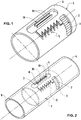
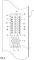
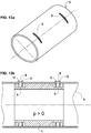
- this metering element 1 shows a metering element 1, which has the shape of a hollow cylinder.
- this metering element 1 comprises an inlet area 2, which is equipped with a filter 3. Through this filter 3, the water from the drip irrigation pipe 4 enters the inlet area 2.
- a metering area 5 Connected to this inlet area 2 is a metering area 5, in which the pressure of the water flowing through is reduced in a known manner. From this metering area 5 the water reaches the outlet area 6, from which the water can be released dropwise into the environment.
- the metering element 1 is inserted into the drip irrigation tube 4 in a known manner, the surfaces of the metering element 1 are connected to the wall 9 of the drip irrigation tube 4 in a known manner, in particular by welding, which takes place in a known manner during the manufacturing process of the drip irrigation tube, the outlet opening has the shape of a slot 8, which extends at least over a partial region of the length of the outlet region 6.
- support means 10 are attached in the outlet region 6 of the metering element 1, which in this first embodiment are designed as two ribs 11, which extend along the slot 8 on both sides, and whose function is described below.
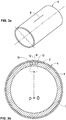
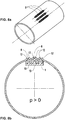
- the metering element 1 can be seen, which has the shape of a hollow cylinder which is inserted into the drip irrigation pipe 4 and connected to it.
- the entry area 2 of the metering element 1 and the slot 8 in the wall 9 are also visible.
- the support means are formed by the two ribs 11. These two ribs 11 are each arranged below an edge region 12 of the slot 8.
- the pressure inside the drip irrigation tube 4 is equal to 0 here, because of the elastic material from which this drip irrigation tube 4 is formed, for example polyethylene, the edge regions 12 which delimit the slot 8 lie on one another, the slot 8 is closed.
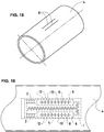
- Fig. 3a can be seen, which shows the drip irrigation pipe 1 with the slot 8 made therein Fig.
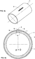
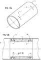
- Fig. 4b shows the drip irrigation pipe 4 with the dosing element 1 inserted therein, the pressure inside the drip irrigation pipe 4 being greater than 0, which state is reached during the irrigation process.
- the inlet area 2 there is also a slightly higher pressure, as a result of which the two edge areas 12 of the slot 8 are raised to the outside and form an opening, the slot 8 thereby allowing the water to escape from the drip irrigation pipe 4.
- the slot 8 in the drip irrigation pipe 4 is open.
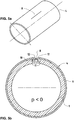
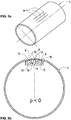
- the pressure inside the drip irrigation pipe 4 collapses and becomes less than 0, as shown in FIG Fig. 5b is shown.
- the drip irrigation pipes 4 are not aligned absolutely horizontally, which is usually the case, the residual water located in the drip irrigation pipe 4 will run at the lowest point of the irrigation system, as a result of which the negative pressure within the drip irrigation pipes 4 comes about.
- This negative pressure can also be found in inlet area 2, a suction effect thus arises on the slot 8, the edge regions 12 of the slot 8 are bent inwards.
- the ribs 11, which form the support means 10, prevent excessive bending, the slot 8 thus remains closed even in this state. This prevents any dirt particles from penetrating into the entry area 2 through the slot 8, which particles then enter the metering area 5 ( Fig. 1 ) would land and could block the flow of water through the metering area 5.
- Fig. 6 shows an embodiment in which the dosing element 1 inserted into the drip irrigation tube 4 has the shape of a plate.
- This metering element in turn comprises an inlet area 2, a filter 3, a metering area 5 and three outlet areas 6 arranged next to one another.
- an outlet opening 7 in the form of a slot 8 is made in the wall 9 of the drip irrigation pipe 4.
- support means 10 are in turn attached, which are designed here as cams 13, each extending across the slot 8 and spaced apart along the slot 8.
- the edge regions 12 of the slots 8 are bent outwards during the irrigation process and if the pressure inside the drip irrigation pipe 4 is greater than 0, the slots 8 are opened and the water can escape through these slots 8.
- the metering element 1 is formed from a hollow cylinder which, as has been described above, is inserted into the drip irrigation pipe 4 and connected to it.
- This metering element 1 has an inlet area 2, in which the filter 3 is arranged, through which the water from the interior of the drip irrigation pipe is conducted via the metering areas 5 into the outlet areas 6.
- These entry areas 6 are designed as grooves 14, which extend over the entire circumference of the metering element 1.
- two parallel ribs 15 are attached, which support the edge regions of the slots 8, which form the outlet openings 7, as will be seen later.
- the slots 8 are arranged transversely to the longitudinal axis of the drip irrigation pipe 4.
- the slots 8 are closed, as previously described.
- the edge regions 12 of the slots 8 are bent outwards so that water can emerge from the slots 8 for irrigation.
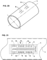
- Fig. 15 shows a drip irrigation pipe 4, in each of which a slot 8 is arranged in the longitudinal direction of the pipe for each metering element.
- Fig. 16 shows that to that in Fig. 15 shown slot 8, a metering element 1 is attached in the form of a plate, with inlet area 2, metering area 5 and outlet area 6, wherein two longitudinal ribs 16 are arranged along the slot 8, which can support the edge regions 12 of the slot 8.
- Fig. 17 shows the same arrangement as in Fig. 16
- the support means 10 in the metering element 1 are designed as cams 13 which can support the edge regions 12 of the slot 8.
- the metering element 1 comprises two inlet areas 2, a metering area 5 and two outlet areas 6, the outlet areas 6 being aligned parallel to one another and in the longitudinal direction of the drip irrigation pipe 4.
- the slots 8 are arranged in the area of the outlet areas 6, the edge areas 12 of these slots 8 are supported by cams 13 which are provided along the slots 8 in the metering element 1.
- the metering element 1 has two inlet areas 2, from which the water reaches a centrally arranged metering area 5, via a branching the water reaches the two outlet areas 6, which are aligned parallel to one another.
- two slots 8 are made in the wall 9 of the drip irrigation pipe 4, the edge areas 12 of which are supported by cams 13.
Claims (10)
- Tuyau d'irrigation de type goutte à goutte (4) doté d'éléments de dosage (1) intégrés, qui sont reliés à la paroi (9) du tuyau d'irrigation de type goutte à goutte (4), lesquels éléments de dosage (1) comprennent chacun des zones d'entrée (2) à travers lesquelles l'eau passe du tuyau (4) dans les éléments de dosage (1), les zones de dosage (5), dans lesquelles une réduction de la pression de l'eau courante a lieu, et des zones de sortie (6), à travers lesquelles l'eau sort du tuyau d'irrigation de type goutte à goutte (4) via des ouvertures de sortie (7) réalisées dans la paroi du tuyau (9), caractérisé en ce que les ouvertures de sortie (7) sont en forme de fente (8), dont les bords (12), sont élevées vers l'extérieur et forment une ouverture durant le processus d'irrigation, et, lorsque le processus d'irrigation est terminé ou interrompu, sont maintenus par des moyens de support (10) de manière à limiter la courbure des bords (12) de la fente (8) vers les éléments de dosage, et les ouvertures de sortie en forme de fente restent fermées.
- Tuyau d'irrigation de type goutte à goutte (4) doté d'éléments de dosage (1) intégrés selon la revendication 1, caractérisé en ce que les moyens de support (10) sont formés directement sur les éléments de dosage (1).
- Tuyau d'irrigation de type goutte à goutte (4) doté d'éléments de dosage (1) intégrés selon la revendication 1 ou 2, caractérisé en ce que les moyens de support (10) sont formés de protrusions (13) qui sont agencées le long de la fente (8) sur les éléments de dosage (1).
- Tuyau d'irrigation de type goutte à goutte (4) doté d'éléments de dosage (1) intégrés selon la revendication 1 ou 2, caractérisé en ce que les moyens de support (10) sont conçus comme des nervures (15 ; 16), qui sont agencées longitudinalement par rapport à leur fente respective (8) sur les éléments de dosage (1).
- Tuyau d'irrigation de type goutte à goutte (4) doté d'éléments de dosage (1) intégrés selon l'une des revendications 1 à 4, caractérisé en ce que chaque élément de dosage (1) comprend au moins une zone de sortie (6).
- Tuyau d'irrigation de type goutte à goutte (4) doté d'éléments de dosage (1) intégrés selon l'une des revendications 1 à 5, caractérisé en ce qu'au moins une ouverture de sortie (7) en forme de fente (8) est prévue pour chaque zone de sortie (6) dans la paroi du tuyau (9).
- Tuyau d'irrigation de type goutte à goutte (4) doté d'éléments de dosage (1) intégrés selon l'une des revendications 1 à 6, caractérisé en ce que les éléments de dosage (1) présentent une forme de cylindre creux.
- Tuyau d'irrigation de type goutte à goutte (4) doté d'éléments de dosage (1) intégrés selon l'une des revendications 1 à 6, caractérisé en ce que les éléments de dosage (1) sont en forme de plaquette ou de bande.
- Tuyau d'irrigation de type goutte à goutte (4) doté d'éléments de dosage (1) intégrés selon l'une des revendications 1 à 8, caractérisé en ce que les fentes (8) sont orientées parallèlement à l'axe longitudinal du tube d'irrigation de type goutte à goutte (4).
- Tuyau d'irrigation de type goutte à goutte (4) doté d'éléments de dosage (1) intégrés selon l'une des revendications 1 à 7, caractérisé en ce que les fentes (8) sont orientées transversalement par rapport à l'axe longitudinal du tuyau d'irrigation de type goutte à goutte (4).
Priority Applications (5)
| Application Number | Priority Date | Filing Date | Title |
|---|---|---|---|
| ES14171418T ES2788600T3 (es) | 2014-06-05 | 2014-06-05 | Tubo de riego por goteo con elementos de dosificación insertados |
| EP14171418.8A EP2952091B1 (fr) | 2014-06-05 | 2014-06-05 | Tuyau d'irrigation goutte à goutte doté d'éléments de dosage intégrés |
| PT141714188T PT2952091T (pt) | 2014-06-05 | 2014-06-05 | Tubo de irrigação gota a gota com elementos de dosagem nele inseridos |
| RS20200352A RS60212B1 (sr) | 2014-06-05 | 2014-06-05 | Cev za navodnjavanje kapanjem sa elementima za doziranje umetnutim u istu |
| CY20201100299T CY1122903T1 (el) | 2014-06-05 | 2020-03-30 | Σωληνας σταγδην αρδευσης με εισηγμενα σε αυτον στοιχεια δοσιμετρησης |
Applications Claiming Priority (1)
| Application Number | Priority Date | Filing Date | Title |
|---|---|---|---|
| EP14171418.8A EP2952091B1 (fr) | 2014-06-05 | 2014-06-05 | Tuyau d'irrigation goutte à goutte doté d'éléments de dosage intégrés |
Publications (2)
| Publication Number | Publication Date |
|---|---|
| EP2952091A1 EP2952091A1 (fr) | 2015-12-09 |
| EP2952091B1 true EP2952091B1 (fr) | 2020-02-05 |
Family
ID=50927955
Family Applications (1)
| Application Number | Title | Priority Date | Filing Date |
|---|---|---|---|
| EP14171418.8A Active EP2952091B1 (fr) | 2014-06-05 | 2014-06-05 | Tuyau d'irrigation goutte à goutte doté d'éléments de dosage intégrés |
Country Status (5)
| Country | Link |
|---|---|
| EP (1) | EP2952091B1 (fr) |
| CY (1) | CY1122903T1 (fr) |
| ES (1) | ES2788600T3 (fr) |
| PT (1) | PT2952091T (fr) |
| RS (1) | RS60212B1 (fr) |
Families Citing this family (12)
| Publication number | Priority date | Publication date | Assignee | Title |
|---|---|---|---|---|
| US7648085B2 (en) | 2006-02-22 | 2010-01-19 | Rain Bird Corporation | Drip emitter |
| US9877440B2 (en) | 2012-03-26 | 2018-01-30 | Rain Bird Corporation | Elastomeric emitter and methods relating to same |
| US10440903B2 (en) | 2012-03-26 | 2019-10-15 | Rain Bird Corporation | Drip line emitter and methods relating to same |
| US10285342B2 (en) | 2013-08-12 | 2019-05-14 | Rain Bird Corporation | Elastomeric emitter and methods relating to same |
| US10631473B2 (en) | 2013-08-12 | 2020-04-28 | Rain Bird Corporation | Elastomeric emitter and methods relating to same |
| US9883640B2 (en) | 2013-10-22 | 2018-02-06 | Rain Bird Corporation | Methods and apparatus for transporting elastomeric emitters and/or manufacturing drip lines |
| US10330559B2 (en) | 2014-09-11 | 2019-06-25 | Rain Bird Corporation | Methods and apparatus for checking emitter bonds in an irrigation drip line |
| US10375904B2 (en) | 2016-07-18 | 2019-08-13 | Rain Bird Corporation | Emitter locating system and related methods |
| US11051466B2 (en) | 2017-01-27 | 2021-07-06 | Rain Bird Corporation | Pressure compensation members, emitters, drip line and methods relating to same |
| TR201706925A2 (tr) * | 2017-05-11 | 2018-11-21 | Drts Sulama Ueruenleri Ve Teknolojileri Sanayi Ticaret Anonim Sirketi | Tarımsal Sulamada Kullanılmak Üzere Bir Damlatıcı Yapılanması |
| US10626998B2 (en) | 2017-05-15 | 2020-04-21 | Rain Bird Corporation | Drip emitter with check valve |
| USD883048S1 (en) | 2017-12-12 | 2020-05-05 | Rain Bird Corporation | Emitter part |
Family Cites Families (5)
| Publication number | Priority date | Publication date | Assignee | Title |
|---|---|---|---|---|
| US6382530B1 (en) * | 2000-07-10 | 2002-05-07 | Nelson Irrigation Corporation | Pressure compensating drip tape |
| US6736337B2 (en) * | 2002-02-08 | 2004-05-18 | The Toro Company | Pressure compensating drip irrigation hose |
| IL212105A (en) * | 2011-04-03 | 2016-07-31 | Einav Zvi | Integral dropper with elongated exit pool |
| GB2496832B (en) * | 2011-05-16 | 2013-11-13 | Uri Alkalay | Cylindrical drip irrigation emitter |
| IL221089A (en) * | 2012-07-24 | 2016-05-31 | Einav Zvi | Integral dropper with easy paddling exit pool |
-
2014
- 2014-06-05 PT PT141714188T patent/PT2952091T/pt unknown
- 2014-06-05 ES ES14171418T patent/ES2788600T3/es active Active
- 2014-06-05 RS RS20200352A patent/RS60212B1/sr unknown
- 2014-06-05 EP EP14171418.8A patent/EP2952091B1/fr active Active
-
2020
- 2020-03-30 CY CY20201100299T patent/CY1122903T1/el unknown
Non-Patent Citations (1)
| Title |
|---|
| None * |
Also Published As
| Publication number | Publication date |
|---|---|
| CY1122903T1 (el) | 2021-10-29 |
| PT2952091T (pt) | 2020-03-31 |
| ES2788600T3 (es) | 2020-10-22 |
| EP2952091A1 (fr) | 2015-12-09 |
| RS60212B1 (sr) | 2020-06-30 |
Similar Documents
| Publication | Publication Date | Title |
|---|---|---|
| EP2952091B1 (fr) | Tuyau d'irrigation goutte à goutte doté d'éléments de dosage intégrés | |
| DE2431516C3 (de) | Vorrichtung zur Abgabe von Fluiden | |
| EP2054558B1 (fr) | Dispositif de drainage | |
| DE2707233A1 (de) | Beregnungsvorrichtung | |
| DE2224320A1 (de) | Ausgabekopf fur Bewässerungsanlagen od dgl | |
| DE2535732A1 (de) | Troepfchenbewaesserungsvorrichtung | |
| DE2852108A1 (de) | Rohrbrunnenfilter | |
| DE2011409A1 (de) | Kupplungshülse zum Kuppeln mit einer Anschlußtülle | |
| EP1918576B1 (fr) | Filtre à carburant | |
| DE202007009832U1 (de) | Anschlussarmatur | |
| DE202017105379U1 (de) | Strahlregler | |
| DE2514233A1 (de) | Duese fuer beregnungsanlagen | |
| EP2508686A1 (fr) | Installation de retenue pour l'eau de précipitation et les eaux usées | |
| DE10063283A1 (de) | Siebfilter für Fluidleitungen, insbesondere für hydraulische Druckleitungen in Brennkraftmaschinen | |
| DE2431513C3 (de) | Mit Drosselwirkung arbeitende Fluidabgabevorrichtung | |
| EP2764768B1 (fr) | Tuyau d'irrigation goutte à goutte avec des éléments de dosage | |
| EP3517211B1 (fr) | Pomme de douche à vanne de surpression | |
| DE102017120521A1 (de) | Strahlregler | |
| DE102013022114B4 (de) | Filtervorrichtung | |
| DE102016104557A1 (de) | Staubsauger-Saugrohr | |
| DE102017128758A1 (de) | Sanitäre Einsetzeinheit | |
| DE19519106B4 (de) | Drosselvorrichtung | |
| DE102016205647A1 (de) | Ringgatter für eine hydraulische Maschine und Verfahren zum Schließen | |
| DE3923028C2 (de) | Drosselelement für Druckleitungen | |
| DE202007014407U1 (de) | Sprühdüse mit der Möglichkeit zum allseitigen Sprühen von Wasser |
Legal Events
| Date | Code | Title | Description |
|---|---|---|---|
| PUAI | Public reference made under article 153(3) epc to a published international application that has entered the european phase |
Free format text: ORIGINAL CODE: 0009012 |
|
| AK | Designated contracting states |
Kind code of ref document: A1 Designated state(s): AL AT BE BG CH CY CZ DE DK EE ES FI FR GB GR HR HU IE IS IT LI LT LU LV MC MK MT NL NO PL PT RO RS SE SI SK SM TR |
|
| AX | Request for extension of the european patent |
Extension state: BA ME |
|
| RIN1 | Information on inventor provided before grant (corrected) |
Inventor name: LOEBINGER, AHAI Inventor name: KERTSCHER, EBERHARD |
|
| 17P | Request for examination filed |
Effective date: 20160606 |
|
| RBV | Designated contracting states (corrected) |
Designated state(s): AL AT BE BG CH CY CZ DE DK EE ES FI FR GB GR HR HU IE IS IT LI LT LU LV MC MK MT NL NO PL PT RO RS SE SI SK SM TR |
|
| STAA | Information on the status of an ep patent application or granted ep patent |
Free format text: STATUS: EXAMINATION IS IN PROGRESS |
|
| 17Q | First examination report despatched |
Effective date: 20170217 |
|
| GRAP | Despatch of communication of intention to grant a patent |
Free format text: ORIGINAL CODE: EPIDOSNIGR1 |
|
| STAA | Information on the status of an ep patent application or granted ep patent |
Free format text: STATUS: GRANT OF PATENT IS INTENDED |
|
| INTG | Intention to grant announced |
Effective date: 20190909 |
|
| GRAS | Grant fee paid |
Free format text: ORIGINAL CODE: EPIDOSNIGR3 |
|
| GRAA | (expected) grant |
Free format text: ORIGINAL CODE: 0009210 |
|
| STAA | Information on the status of an ep patent application or granted ep patent |
Free format text: STATUS: THE PATENT HAS BEEN GRANTED |
|
| AK | Designated contracting states |
Kind code of ref document: B1 Designated state(s): AL AT BE BG CH CY CZ DE DK EE ES FI FR GB GR HR HU IE IS IT LI LT LU LV MC MK MT NL NO PL PT RO RS SE SI SK SM TR |
|
| REG | Reference to a national code |
Ref country code: GB Ref legal event code: FG4D Free format text: NOT ENGLISH |
|
| REG | Reference to a national code |
Ref country code: AT Ref legal event code: REF Ref document number: 1229298 Country of ref document: AT Kind code of ref document: T Effective date: 20200215 |
|
| REG | Reference to a national code |
Ref country code: DE Ref legal event code: R096 Ref document number: 502014013548 Country of ref document: DE |
|
| REG | Reference to a national code |
Ref country code: IE Ref legal event code: FG4D Free format text: LANGUAGE OF EP DOCUMENT: GERMAN |
|
| REG | Reference to a national code |
Ref country code: RO Ref legal event code: EPE |
|
| REG | Reference to a national code |
Ref country code: PT Ref legal event code: SC4A Ref document number: 2952091 Country of ref document: PT Date of ref document: 20200331 Kind code of ref document: T Free format text: AVAILABILITY OF NATIONAL TRANSLATION Effective date: 20200323 Ref country code: CH Ref legal event code: EP |
|
| REG | Reference to a national code |
Ref country code: CH Ref legal event code: NV Representative=s name: BOVARD AG PATENT- UND MARKENANWAELTE, CH |
|
| REG | Reference to a national code |
Ref country code: GR Ref legal event code: EP Ref document number: 20200401128 Country of ref document: GR Effective date: 20200615 |
|
| REG | Reference to a national code |
Ref country code: NL Ref legal event code: MP Effective date: 20200205 |
|
| PG25 | Lapsed in a contracting state [announced via postgrant information from national office to epo] |
Ref country code: NO Free format text: LAPSE BECAUSE OF FAILURE TO SUBMIT A TRANSLATION OF THE DESCRIPTION OR TO PAY THE FEE WITHIN THE PRESCRIBED TIME-LIMIT Effective date: 20200505 Ref country code: FI Free format text: LAPSE BECAUSE OF FAILURE TO SUBMIT A TRANSLATION OF THE DESCRIPTION OR TO PAY THE FEE WITHIN THE PRESCRIBED TIME-LIMIT Effective date: 20200205 |
|
| REG | Reference to a national code |
Ref country code: LT Ref legal event code: MG4D |
|
| PG25 | Lapsed in a contracting state [announced via postgrant information from national office to epo] |
Ref country code: HR Free format text: LAPSE BECAUSE OF FAILURE TO SUBMIT A TRANSLATION OF THE DESCRIPTION OR TO PAY THE FEE WITHIN THE PRESCRIBED TIME-LIMIT Effective date: 20200205 Ref country code: LV Free format text: LAPSE BECAUSE OF FAILURE TO SUBMIT A TRANSLATION OF THE DESCRIPTION OR TO PAY THE FEE WITHIN THE PRESCRIBED TIME-LIMIT Effective date: 20200205 Ref country code: SE Free format text: LAPSE BECAUSE OF FAILURE TO SUBMIT A TRANSLATION OF THE DESCRIPTION OR TO PAY THE FEE WITHIN THE PRESCRIBED TIME-LIMIT Effective date: 20200205 Ref country code: IS Free format text: LAPSE BECAUSE OF FAILURE TO SUBMIT A TRANSLATION OF THE DESCRIPTION OR TO PAY THE FEE WITHIN THE PRESCRIBED TIME-LIMIT Effective date: 20200605 |
|
| PG25 | Lapsed in a contracting state [announced via postgrant information from national office to epo] |
Ref country code: NL Free format text: LAPSE BECAUSE OF FAILURE TO SUBMIT A TRANSLATION OF THE DESCRIPTION OR TO PAY THE FEE WITHIN THE PRESCRIBED TIME-LIMIT Effective date: 20200205 |
|
| REG | Reference to a national code |
Ref country code: ES Ref legal event code: FG2A Ref document number: 2788600 Country of ref document: ES Kind code of ref document: T3 Effective date: 20201022 |
|
| PG25 | Lapsed in a contracting state [announced via postgrant information from national office to epo] |
Ref country code: LT Free format text: LAPSE BECAUSE OF FAILURE TO SUBMIT A TRANSLATION OF THE DESCRIPTION OR TO PAY THE FEE WITHIN THE PRESCRIBED TIME-LIMIT Effective date: 20200205 Ref country code: CZ Free format text: LAPSE BECAUSE OF FAILURE TO SUBMIT A TRANSLATION OF THE DESCRIPTION OR TO PAY THE FEE WITHIN THE PRESCRIBED TIME-LIMIT Effective date: 20200205 Ref country code: SM Free format text: LAPSE BECAUSE OF FAILURE TO SUBMIT A TRANSLATION OF THE DESCRIPTION OR TO PAY THE FEE WITHIN THE PRESCRIBED TIME-LIMIT Effective date: 20200205 Ref country code: EE Free format text: LAPSE BECAUSE OF FAILURE TO SUBMIT A TRANSLATION OF THE DESCRIPTION OR TO PAY THE FEE WITHIN THE PRESCRIBED TIME-LIMIT Effective date: 20200205 Ref country code: SK Free format text: LAPSE BECAUSE OF FAILURE TO SUBMIT A TRANSLATION OF THE DESCRIPTION OR TO PAY THE FEE WITHIN THE PRESCRIBED TIME-LIMIT Effective date: 20200205 Ref country code: DK Free format text: LAPSE BECAUSE OF FAILURE TO SUBMIT A TRANSLATION OF THE DESCRIPTION OR TO PAY THE FEE WITHIN THE PRESCRIBED TIME-LIMIT Effective date: 20200205 |
|
| REG | Reference to a national code |
Ref country code: DE Ref legal event code: R097 Ref document number: 502014013548 Country of ref document: DE |
|
| PLBE | No opposition filed within time limit |
Free format text: ORIGINAL CODE: 0009261 |
|
| STAA | Information on the status of an ep patent application or granted ep patent |
Free format text: STATUS: NO OPPOSITION FILED WITHIN TIME LIMIT |
|
| 26N | No opposition filed |
Effective date: 20201106 |
|
| PG25 | Lapsed in a contracting state [announced via postgrant information from national office to epo] |
Ref country code: MC Free format text: LAPSE BECAUSE OF FAILURE TO SUBMIT A TRANSLATION OF THE DESCRIPTION OR TO PAY THE FEE WITHIN THE PRESCRIBED TIME-LIMIT Effective date: 20200205 |
|
| PG25 | Lapsed in a contracting state [announced via postgrant information from national office to epo] |
Ref country code: PL Free format text: LAPSE BECAUSE OF FAILURE TO SUBMIT A TRANSLATION OF THE DESCRIPTION OR TO PAY THE FEE WITHIN THE PRESCRIBED TIME-LIMIT Effective date: 20200205 Ref country code: SI Free format text: LAPSE BECAUSE OF FAILURE TO SUBMIT A TRANSLATION OF THE DESCRIPTION OR TO PAY THE FEE WITHIN THE PRESCRIBED TIME-LIMIT Effective date: 20200205 |
|
| GBPC | Gb: european patent ceased through non-payment of renewal fee |
Effective date: 20200605 |
|
| PG25 | Lapsed in a contracting state [announced via postgrant information from national office to epo] |
Ref country code: LU Free format text: LAPSE BECAUSE OF NON-PAYMENT OF DUE FEES Effective date: 20200605 |
|
| REG | Reference to a national code |
Ref country code: BE Ref legal event code: MM Effective date: 20200630 |
|
| PG25 | Lapsed in a contracting state [announced via postgrant information from national office to epo] |
Ref country code: IE Free format text: LAPSE BECAUSE OF NON-PAYMENT OF DUE FEES Effective date: 20200605 Ref country code: GB Free format text: LAPSE BECAUSE OF NON-PAYMENT OF DUE FEES Effective date: 20200605 |
|
| PG25 | Lapsed in a contracting state [announced via postgrant information from national office to epo] |
Ref country code: BE Free format text: LAPSE BECAUSE OF NON-PAYMENT OF DUE FEES Effective date: 20200630 |
|
| REG | Reference to a national code |
Ref country code: AT Ref legal event code: MM01 Ref document number: 1229298 Country of ref document: AT Kind code of ref document: T Effective date: 20200605 |
|
| PG25 | Lapsed in a contracting state [announced via postgrant information from national office to epo] |
Ref country code: AT Free format text: LAPSE BECAUSE OF NON-PAYMENT OF DUE FEES Effective date: 20200605 |
|
| PG25 | Lapsed in a contracting state [announced via postgrant information from national office to epo] |
Ref country code: MT Free format text: LAPSE BECAUSE OF FAILURE TO SUBMIT A TRANSLATION OF THE DESCRIPTION OR TO PAY THE FEE WITHIN THE PRESCRIBED TIME-LIMIT Effective date: 20200205 |
|
| PG25 | Lapsed in a contracting state [announced via postgrant information from national office to epo] |
Ref country code: MK Free format text: LAPSE BECAUSE OF FAILURE TO SUBMIT A TRANSLATION OF THE DESCRIPTION OR TO PAY THE FEE WITHIN THE PRESCRIBED TIME-LIMIT Effective date: 20200205 Ref country code: AL Free format text: LAPSE BECAUSE OF FAILURE TO SUBMIT A TRANSLATION OF THE DESCRIPTION OR TO PAY THE FEE WITHIN THE PRESCRIBED TIME-LIMIT Effective date: 20200205 |
|
| PGFP | Annual fee paid to national office [announced via postgrant information from national office to epo] |
Ref country code: RS Payment date: 20230525 Year of fee payment: 10 Ref country code: RO Payment date: 20230525 Year of fee payment: 10 Ref country code: PT Payment date: 20230525 Year of fee payment: 10 Ref country code: FR Payment date: 20230628 Year of fee payment: 10 Ref country code: DE Payment date: 20230620 Year of fee payment: 10 Ref country code: CY Payment date: 20230601 Year of fee payment: 10 Ref country code: BG Payment date: 20230627 Year of fee payment: 10 |
|
| P01 | Opt-out of the competence of the unified patent court (upc) registered |
Effective date: 20230630 |
|
| PGFP | Annual fee paid to national office [announced via postgrant information from national office to epo] |
Ref country code: TR Payment date: 20230602 Year of fee payment: 10 Ref country code: GR Payment date: 20230621 Year of fee payment: 10 |
|
| PGFP | Annual fee paid to national office [announced via postgrant information from national office to epo] |
Ref country code: IT Payment date: 20230621 Year of fee payment: 10 Ref country code: ES Payment date: 20230829 Year of fee payment: 10 Ref country code: CH Payment date: 20230702 Year of fee payment: 10 |