EP2950848B1 - Dispositif de liaison comportant un dispositif de blocage à relier à un dispositif destiné à fermer des voies fluidiques, dispositif de contrôle de l'état du dispositif de blocage et procédé correspondant - Google Patents
Dispositif de liaison comportant un dispositif de blocage à relier à un dispositif destiné à fermer des voies fluidiques, dispositif de contrôle de l'état du dispositif de blocage et procédé correspondant Download PDFInfo
- Publication number
- EP2950848B1 EP2950848B1 EP14703312.0A EP14703312A EP2950848B1 EP 2950848 B1 EP2950848 B1 EP 2950848B1 EP 14703312 A EP14703312 A EP 14703312A EP 2950848 B1 EP2950848 B1 EP 2950848B1
- Authority
- EP
- European Patent Office
- Prior art keywords
- clamping
- clamping device
- pressure
- measuring unit
- distance
- Prior art date
- Legal status (The legal status is an assumption and is not a legal conclusion. Google has not performed a legal analysis and makes no representation as to the accuracy of the status listed.)
- Active
Links
Images

Classifications
-
- A—HUMAN NECESSITIES
- A61—MEDICAL OR VETERINARY SCIENCE; HYGIENE
- A61M—DEVICES FOR INTRODUCING MEDIA INTO, OR ONTO, THE BODY; DEVICES FOR TRANSDUCING BODY MEDIA OR FOR TAKING MEDIA FROM THE BODY; DEVICES FOR PRODUCING OR ENDING SLEEP OR STUPOR
- A61M39/00—Tubes, tube connectors, tube couplings, valves, access sites or the like, specially adapted for medical use
- A61M39/22—Valves or arrangement of valves
- A61M39/28—Clamping means for squeezing flexible tubes, e.g. roller clamps
-
- F—MECHANICAL ENGINEERING; LIGHTING; HEATING; WEAPONS; BLASTING
- F16—ENGINEERING ELEMENTS AND UNITS; GENERAL MEASURES FOR PRODUCING AND MAINTAINING EFFECTIVE FUNCTIONING OF MACHINES OR INSTALLATIONS; THERMAL INSULATION IN GENERAL
- F16K—VALVES; TAPS; COCKS; ACTUATING-FLOATS; DEVICES FOR VENTING OR AERATING
- F16K37/00—Special means in or on valves or other cut-off apparatus for indicating or recording operation thereof, or for enabling an alarm to be given
- F16K37/0075—For recording or indicating the functioning of a valve in combination with test equipment
- F16K37/0091—For recording or indicating the functioning of a valve in combination with test equipment by measuring fluid parameters
-
- A—HUMAN NECESSITIES
- A61—MEDICAL OR VETERINARY SCIENCE; HYGIENE
- A61M—DEVICES FOR INTRODUCING MEDIA INTO, OR ONTO, THE BODY; DEVICES FOR TRANSDUCING BODY MEDIA OR FOR TAKING MEDIA FROM THE BODY; DEVICES FOR PRODUCING OR ENDING SLEEP OR STUPOR
- A61M1/00—Suction or pumping devices for medical purposes; Devices for carrying-off, for treatment of, or for carrying-over, body-liquids; Drainage systems
- A61M1/36—Other treatment of blood in a by-pass of the natural circulatory system, e.g. temperature adaptation, irradiation ; Extra-corporeal blood circuits
- A61M1/3621—Extra-corporeal blood circuits
- A61M1/3639—Blood pressure control, pressure transducers specially adapted therefor
- A61M1/3641—Pressure isolators
-
- A—HUMAN NECESSITIES
- A61—MEDICAL OR VETERINARY SCIENCE; HYGIENE
- A61M—DEVICES FOR INTRODUCING MEDIA INTO, OR ONTO, THE BODY; DEVICES FOR TRANSDUCING BODY MEDIA OR FOR TAKING MEDIA FROM THE BODY; DEVICES FOR PRODUCING OR ENDING SLEEP OR STUPOR
- A61M1/00—Suction or pumping devices for medical purposes; Devices for carrying-off, for treatment of, or for carrying-over, body-liquids; Drainage systems
- A61M1/36—Other treatment of blood in a by-pass of the natural circulatory system, e.g. temperature adaptation, irradiation ; Extra-corporeal blood circuits
- A61M1/3621—Extra-corporeal blood circuits
- A61M1/367—Circuit parts not covered by the preceding subgroups of group A61M1/3621
-
- F—MECHANICAL ENGINEERING; LIGHTING; HEATING; WEAPONS; BLASTING
- F16—ENGINEERING ELEMENTS AND UNITS; GENERAL MEASURES FOR PRODUCING AND MAINTAINING EFFECTIVE FUNCTIONING OF MACHINES OR INSTALLATIONS; THERMAL INSULATION IN GENERAL
- F16K—VALVES; TAPS; COCKS; ACTUATING-FLOATS; DEVICES FOR VENTING OR AERATING
- F16K37/00—Special means in or on valves or other cut-off apparatus for indicating or recording operation thereof, or for enabling an alarm to be given
- F16K37/0075—For recording or indicating the functioning of a valve in combination with test equipment
- F16K37/0083—For recording or indicating the functioning of a valve in combination with test equipment by measuring valve parameters
-
- F—MECHANICAL ENGINEERING; LIGHTING; HEATING; WEAPONS; BLASTING
- F16—ENGINEERING ELEMENTS AND UNITS; GENERAL MEASURES FOR PRODUCING AND MAINTAINING EFFECTIVE FUNCTIONING OF MACHINES OR INSTALLATIONS; THERMAL INSULATION IN GENERAL
- F16K—VALVES; TAPS; COCKS; ACTUATING-FLOATS; DEVICES FOR VENTING OR AERATING
- F16K7/00—Diaphragm valves or cut-off apparatus, e.g. with a member deformed, but not moved bodily, to close the passage ; Pinch valves
- F16K7/02—Diaphragm valves or cut-off apparatus, e.g. with a member deformed, but not moved bodily, to close the passage ; Pinch valves with tubular diaphragm
- F16K7/04—Diaphragm valves or cut-off apparatus, e.g. with a member deformed, but not moved bodily, to close the passage ; Pinch valves with tubular diaphragm constrictable by external radial force
-
- A—HUMAN NECESSITIES
- A61—MEDICAL OR VETERINARY SCIENCE; HYGIENE
- A61M—DEVICES FOR INTRODUCING MEDIA INTO, OR ONTO, THE BODY; DEVICES FOR TRANSDUCING BODY MEDIA OR FOR TAKING MEDIA FROM THE BODY; DEVICES FOR PRODUCING OR ENDING SLEEP OR STUPOR
- A61M2205/00—General characteristics of the apparatus
- A61M2205/14—Detection of the presence or absence of a tube, a connector or a container in an apparatus
-
- A—HUMAN NECESSITIES
- A61—MEDICAL OR VETERINARY SCIENCE; HYGIENE
- A61M—DEVICES FOR INTRODUCING MEDIA INTO, OR ONTO, THE BODY; DEVICES FOR TRANSDUCING BODY MEDIA OR FOR TAKING MEDIA FROM THE BODY; DEVICES FOR PRODUCING OR ENDING SLEEP OR STUPOR
- A61M2205/00—General characteristics of the apparatus
- A61M2205/33—Controlling, regulating or measuring
- A61M2205/332—Force measuring means
-
- Y—GENERAL TAGGING OF NEW TECHNOLOGICAL DEVELOPMENTS; GENERAL TAGGING OF CROSS-SECTIONAL TECHNOLOGIES SPANNING OVER SEVERAL SECTIONS OF THE IPC; TECHNICAL SUBJECTS COVERED BY FORMER USPC CROSS-REFERENCE ART COLLECTIONS [XRACs] AND DIGESTS
- Y10—TECHNICAL SUBJECTS COVERED BY FORMER USPC
- Y10T—TECHNICAL SUBJECTS COVERED BY FORMER US CLASSIFICATION
- Y10T137/00—Fluid handling
- Y10T137/0318—Processes
-
- Y—GENERAL TAGGING OF NEW TECHNOLOGICAL DEVELOPMENTS; GENERAL TAGGING OF CROSS-SECTIONAL TECHNOLOGIES SPANNING OVER SEVERAL SECTIONS OF THE IPC; TECHNICAL SUBJECTS COVERED BY FORMER USPC CROSS-REFERENCE ART COLLECTIONS [XRACs] AND DIGESTS
- Y10—TECHNICAL SUBJECTS COVERED BY FORMER USPC
- Y10T—TECHNICAL SUBJECTS COVERED BY FORMER US CLASSIFICATION
- Y10T137/00—Fluid handling
- Y10T137/8158—With indicator, register, recorder, alarm or inspection means
- Y10T137/8225—Position or extent of motion indicator
-
- Y—GENERAL TAGGING OF NEW TECHNOLOGICAL DEVELOPMENTS; GENERAL TAGGING OF CROSS-SECTIONAL TECHNOLOGIES SPANNING OVER SEVERAL SECTIONS OF THE IPC; TECHNICAL SUBJECTS COVERED BY FORMER USPC CROSS-REFERENCE ART COLLECTIONS [XRACs] AND DIGESTS
- Y10—TECHNICAL SUBJECTS COVERED BY FORMER USPC
- Y10T—TECHNICAL SUBJECTS COVERED BY FORMER US CLASSIFICATION
- Y10T137/00—Fluid handling
- Y10T137/8158—With indicator, register, recorder, alarm or inspection means
- Y10T137/8326—Fluid pressure responsive indicator, recorder or alarm
Definitions
- the present invention relates to a connecting device with an external functional device for connecting to an arrangement and for closing flow paths by receiving a clamping device wherein a pressure measuring unit and / or a length measuring unit is adapted for detecting a clamping force and / or a distance, so that a condition monitoring of the clamping device is possible.
- connecting devices for connecting an external functional device with an arrangement for treatment, diagnostic methods and the like as they are used in particular in the field of medical technology known.
- such connectors are used in arrays for the treatment of blood in extracorporeal blood circuits.
- the connecting devices are also equipped with various components, which assign a defined functionality to the connecting devices. These components are, for example, sensors or actuators that perform a specific function within the device (for example Pressure measurement).
- the known arrangements still include clamping or valve devices for opening and closing fluid paths.
- connection device for connecting at least one external functional device to an arrangement by means of pressing the external functional device between two contact points.
- the connecting device is equipped with a pressure measuring unit, for measuring a pressure in a pressure measuring device, which represents the external functional device.
- the connection device is, by the combination of the pressure measuring unit with the pressure measuring device, assigned the defined function of a pressure measurement within the arrangement.
- the DE 44 19 593 describes a device for measuring a fluid pressure.
- the described device is equipped with a pressure measuring unit to measure a fluid pressure within a pressure measuring device.
- the connection device in combination with the pressure measuring unit and the pressure measuring device is assigned the defined function of a pressure measurement.
- the US 5,445,613 discloses a clamping device for gradually closing a flexible tube, which is thereby pressed between two clamping surfaces.
- the invention is based on the object of configuring the connection devices known from the prior art for connection to an arrangement in order to be able to carry out treatment, diagnosis methods and the like on which complex flow schemes are based. Furthermore, by adapting the connection devices, a flexible adaptation of the various methods to the existing arrangement and thus a universal use of the arrangement are made possible.
- the task is to further develop the connection device such that free, unnecessary connection devices within an arrangement, another, new or additional function, instead of their original, can take over.
- a connecting device with an external functional device for connection to an arrangement comprising a receiving device for receiving the external functional device, an outer support, a substantially cylindrical inner support and a movable center support, a pressure measuring unit for Measuring the pressure in the external functional device and / or a length measuring unit for measuring a distance, a Power transmission device for continuously displacing the movable center support along the path, an external functional device inserted.
- the external functional device is designed in the form of clamping or valve devices and provided with clamping elements for closing a flow path.
- a pressure measuring unit for detecting a clamping or closing force and / or a length measuring unit for measuring a distance between a first end point and a second end point
- a length measuring unit for measuring a distance between a first end point and a second end point
- connection means for connecting the connection device and closing flow paths in an existing arrangement.
- connection device configured in this way is replaced with its original function, with a different, new or further functionality.
- the object of the invention is further achieved by a method according to claims 9 to 11.
- complex treatment, diagnostic methods or the like are to be understood as those methods which, on the basis of their process-specific Requires more clamping or valve devices than are available in the corresponding conventional arrangements.
- the “external functional devices" as used in the sense of the invention are clamping or valve devices with clamping or valve elements.
- the clamping or valve devices may preferably be designed as disposable articles.
- clamping or valve devices devices which are suitable for shutting off or regulating flow rates of fluids.
- closing is to be understood as meaning the reduction or a complete interruption of a fluid flow in a fluid-carrying element, within the meaning of the invention.
- an “assembly” may be a medical device such as a blood treatment device, a dialysis device, particularly an apheresis or plasma apheresis device, a laboratory-scale device, in drug or food manufacturing, or the like.
- bonding can be a functional and / or mechanical joining of the external functional device, in the form of a clamping or valve device with an arrangement, wherein the clamping device is in contact with at least one measuring device on the side of the device around a clamp - or closing force and / or to determine a distance.
- a "power transmission device” is for transmitting a force within an assembly to components in the connection device.
- the force can be transmitted in mechanical, pneumatic, hydraulic, electrical, electromagnetic, inductive or in any other suitable way.
- the “components” for state monitoring are primarily sensors or actuators, in particular measuring units, such as pressure measuring units and length measuring units.
- the "length measuring unit” as used in the context of the invention is attached to the moving parts of the connecting device. In a particular embodiment, this is located in the outer support of the connecting device. In a movable center support of the connecting device for this purpose a diaphragm is attached, via which a distance (S) can be detected by means of a light barrier in order to be able to determine different opening and closing states of the clamping device.
- the "pressure measuring unit" as used herein is primarily adapted to serve as an abutment for the clamping device to detect a clamping force.
- the pressure measuring unit can also be used in combination with the condition monitoring of the clamping device for measuring a fluid pressure.
- the arrangement can be used flexibly and universally for a variety of treatment, diagnostic methods or the like, which require more than the clamping devices present in the arrangement.
- the adaptation of the connecting device in an arrangement to the respective specific requirements for a method, with regard to the required clamping functions, is fast, easy and safe to carry out.
- no time-consuming and costly civil engineering measures must be performed on an arrangement.
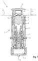
- Connectors (2) as they look FIG. 1 contain three nested hollow body.
- the outer of the three hollow body is referred to as external support (3). It can be flange-mounted on the face side rigidly, ie firmly integrated, in the interior of an arrangement (1), for example a blood treatment machine, at the level of a coupling surface (A) for connecting an external functional device (4).
- the coupling surface (A) is a portion on the top of an outer support (3). However, it may also be an outer sensor surface or a projection (5) of a pressure-measuring unit (7) firmly integrated with the inner support (6) or any portion suitable for receiving a force.
- the substantially cylindrical inner support (6) is held coaxially with the outer support (3) by means of a rigid radial connecting support (8).
- the pressure measuring unit (7) with pressure-sensitive membrane (9) carried by the inner support (6) is always arranged in the same position relative to the coupling surface (A).
- FIG. 1 illustrated lower free end of the outer support (3) is closed by a bottom and has a power transmission connection (10).
- an upper and a lower center support (11) is provided.
- the lower center girder is in Fig. 1 shown as a spring dowel.
- These two hollow bodies are in each case and separated from each other axially within the outer support (3) displaceable.
- the center support (11) can also be integrally formed.
- a pressure plate (12) In the movable center support (11) is below a pressure plate (12) has a recess which is referred to as receiving means (13) and is provided for receiving the external functional device (4).
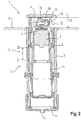
- connection device (2) which now as an external functional device (4) a clamping or valve device (18), for example, a hose clamp, in the open state, wherein the clamping device (18), a fluid-carrying element (23) and clamping elements ( 19, 19 ').
- a clamping or valve device (18) for example, a hose clamp
- a clamping or closing force and / or a distance (S) is detected and determined by means of an evaluation unit (not shown) of the opening or closing state of the clamping devices (18).
- an evaluation unit not shown
- intermediate positions can also be detected.
- the center carrier (11) within the outer support (3) of the connecting device (2) is displaced so as to transmit a force via the pressure-sensitive membrane (9) of the pressure measuring unit (7) and / or a distance (S) to be able to detect a length measuring unit (15).
- the power transmission can be effected in particular pneumatically or hydraulically via a power transmission connection (10).
- the clamping device (18) as a fluid-carrying element (23) have a flow chamber (31), which also represents the housing (25) of the clamping device (18) simultaneously.
- the flow chamber (31) contains a lower side (24) which has sealing contours (32).
- The, the sealing contours (32) facing the lower side (24) can be completed by a flexible membrane (33).
- the upper side (26), which is directed to the pressure plate (12) is preferably limited by a rigid wall.
- the laterally disposed brackets (27), (27 ') are advantageously designed rigidly and form a flow connection, which can be connected in front of and behind the flow chamber (31) in the form of a hose, pipe, channel or the like with an arrangement (1).
- the membrane (33) In the open state, the membrane (33) is not fluid-tight on the underside of the sealing contours (32), so that between the membrane (33) and the sealing contours (32) forms a gap.
- the fluid flowing into the flow chamber (31) flows around the sealing contours (32) and thereby enables fluid flow.
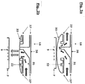
- the sealing contours (32) can be formed by at least two rings in the housing, which are separated by a gap.
- the sealing contours (32) in the flow chamber (31) of the clamping device (18) are preferably arranged concentrically, which may be circular or deviating from the circular shape and are arranged on the membrane side at the same height.
- the membrane (33) can be glued, welded, clamped or crimped on the lower side (24), preferably on the outermost ring of the sealing contour (32) with the housing (25) of the clamping device (18).
- a clamping action will, as in Fig. 3b represented, achieved by pressing the flexible membrane (33) to the sealing contours (32).
- a force transfer device (17) an activation or adjusting force or counterforce force can be exerted on the center carrier (11) of the connecting device.
- This causes the flexible membrane (33) depending on the strength the force application of the receiving device (13) between the lower edge of the sealing contours (32) and the pressure measuring unit (7) of the connecting device (2) can be clamped different degrees of strength.
- the pressure plate (12) is moved away from the coupling surface (A) and transferred to the, in the receiving device (13), clamping device (18) in an open state.
- the pressure plate (12) of the receiving device (13) moves towards the coupling surface (A).
- The, on the flexible membrane (33) of the clamping device (18), transmitted clamping or closing force is measured via the pressure-sensitive membrane (9) of the pressure measuring unit (7).
- an evaluation unit (not shown) can be determined whether the clamping device (18) is in an open or closed state or in an intermediate position.
- the connecting device (2) may be designed such that in addition to a monitoring with respect to a closed state of the clamping device (18) via the Detecting a distance (S) by means of a length measuring unit (15) and a pressure measurement in the flow chamber (31) of the clamping device (18) can be performed.
- the flexible bottom region (30) of the clamping device (18) with the pressure-sensitive membrane (9) of the pressure measuring unit (7) come into contact such that in the closed state, ie when the fluid flow in the flow chamber (31) is interrupted, a fluid pressure in the flow chamber (31) can be measured.
- the pressure measurement can be used to check whether an upstream pump is operating properly or the storage container is open or whether a flow resistance or leakage in the fluid-supplying lines is possible.
- clamping devices (18) may be designed as disposable articles.
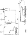
- connection devices (2) with clamping devices (18) for connecting to an arrangement (1) and for closing flow paths as well as condition monitoring will be explained in more detail by way of example on a flow chart for extracorporeal blood treatment, in particular plasma apheresis treatment.
- a pump P1
- a plasma filter 3
- the remaining Blood components are returned to the patient via a second blood line (36).
- the separated plasma passes via a plasma line (37) into an adsorber (38), where unwanted components are bound and the thus purified plasma via a second plasma (43) and a second blood line (36) is fed back to the patient.
- the components adsorbed from the plasma are first washed from the adsorber material with a strong acid. Afterwards, the adsorbent material is neutralized and finally rinsed with a physiological solution. The spent regeneration fluid is drained via a drainage line (44) into a drainage container (45).
- the cleaning solutions are in part aggressive, non-physiological solutions, it is absolutely necessary during regeneration for the solutions to be passed into the adsorber (38) in a specific sequence and for mixing and / or introduction during the regeneration phase the cleaning solutions comes into the patient.
- the fluid lines (39) to the Regenerationsfluid mattersnissen (40, 41, 42) can be securely closed and monitoring the clamping function is possible.
- the connecting devices (2) used in the known arrangements (1) are equipped with function devices (4) for pressure measurement and therefore for closing fluid paths and for condition monitoring a clamping device (18) unsuitable.
- the adapted connecting devices (2) Since during the regeneration phase the originally provided connecting devices (2) are not required at the positions p5 to p7 with an external functional device for measuring pressure, but additional terminals are required, it is now possible with the adapted connecting devices (2) to provide a functional device (4). with clamping device (18) in a receiving device (13) and thereby to adapt a pressure measuring unit (7) for detecting a clamping or closing force and / or a length measuring unit (15) for measuring a distance (S) to a condition monitoring of the clamping device (18 ) automatically.
- Fig. 5 shows the above flow diagram with the adapted connection means (2) at the positions p5 ', p6' and p7 'as external functional means (4) for condition monitoring of the clamping devices (18).
- all the connecting devices (2) for which further clamping devices are required for example for the pressure measuring devices at the positions p1, p2, p3 and / or p4 as described, adapted. This may also be the case when additional dialysate or drug solutions must be administered in a treatment, diagnostic or the like.
Landscapes
- Health & Medical Sciences (AREA)
- Heart & Thoracic Surgery (AREA)
- Engineering & Computer Science (AREA)
- Vascular Medicine (AREA)
- Life Sciences & Earth Sciences (AREA)
- Veterinary Medicine (AREA)
- Biomedical Technology (AREA)
- Hematology (AREA)
- Anesthesiology (AREA)
- Animal Behavior & Ethology (AREA)
- General Health & Medical Sciences (AREA)
- Public Health (AREA)
- General Engineering & Computer Science (AREA)
- Cardiology (AREA)
- Mechanical Engineering (AREA)
- Pulmonology (AREA)
- External Artificial Organs (AREA)
- Orthopedics, Nursing, And Contraception (AREA)
- Infusion, Injection, And Reservoir Apparatuses (AREA)
Claims (11)
- Dispositif de connexion (2) à un dispositif fonctionnel externe (4) pour la connexion à un système (1), le dispositif de connexion comportant- un dispositif récepteur (13) destiné à recevoir le dispositif fonctionnel externe (4),- un support extérieur (3), un support intérieur (6) sensiblement cylindrique et un support central mobile (11),- une unité de mesure de pression (7) pour mesurer la pression dans le dispositif fonctionnel externe (4) et/ou- une unité de mesure de longueur (15) pour la mesure d'une trajectoire (S),- un dispositif de transmission de force (17) pour déplacer en continu le support central mobile (11) le long de la trajectoire (S),- le dispositif fonctionnel externe (4) étant un dispositif de serrage (18) servant à fermer une voie d'écoulement,- le dispositif de serrage (18) disposant d'un boîtier (25), d'un élément conducteur de fluide (23) et d'éléments de serrage (19), et- l'unité de mesure de pression (7) étant apte à détecter une force de serrage et/ou- l'unité de mesure de longueur (15) étant apte à mesurer une trajectoire (S) entre un premier point terminal (20) et un second point terminal (21)- et permettant ainsi une surveillance d'état du dispositif de serrage (18),
caractérisé en ce que- l'élément conducteur de fluide (23) est une chambre d'écoulement (31),- les éléments de serrage (19) sont constitués par des contours d'étanchéité (32) dans le boîtier (25),- le boîtier (25) présentant une face inférieure (24) tournée vers les contours d'étanchéité (32) et qui est limitée par une membrane flexible (33) et une face supérieure (26) qui est constituée par une paroi rigide. - Dispositif de connexion (2) selon la revendication 1, caractérisé en ce que la trajectoire (S) entre un premier point terminal (20) et un second point terminal (21) est définie par l'éloignement entre une paroi rigide (26) du dispositif de serrage (18) en état ouvert et les contours d'étanchéité (32) du dispositif de serrage (18) en état fermé, qui est détecté par une unité de mesure de longueur (15).
- Dispositif de connexion (2) selon la revendication 2, caractérisé en ce que la trajectoire (S) entre le dispositif de serrage (18) en état ouvert et le dispositif de serrage (18) en état fermé est définie par les dimensions du dispositif de serrage (18) et du dispositif récepteur (13).
- Dispositif de connexion (2) selon la revendication 1, caractérisé en ce que la face inférieure (24) du dispositif de serrage (18) présente une partie fond rigide (29) et une partie fond souple (30).
- Dispositif de connexion (2) selon la revendication 4, caractérisé en ce que la partie fond souple (30) du dispositif de serrage (18) en état fermé est apte à mesurer une pression de fluide dans la chambre d'écoulement (31) au moyen de la membrane sensible à la pression (9) dans l'unité de mesure de pression (7) .
- Dispositif de connexion (2) selon la revendication 1, caractérisé en ce que les contours d'étanchéité (32) sont formés par au moins deux anneaux dans le boîtier (25) du dispositif de serrage (18).
- Dispositif de connexion (2) selon la revendication 6, caractérisé en ce que les contours d'étanchéité (32) dans le boîtier (25) du dispositif de serrage (18) sont disposés concentriquement, ceux-ci pouvant être réalisés en une forme de cercle ou une forme différente de la forme de cercle et étant disposés à la même hauteur au niveau de la membrane.
- Dispositif de connexion (2) selon les revendications 4 et 7, caractérisé en ce que la partie intérieure souple (30) est connectée à la partie extérieure rigide (29) par soudage, collage, serrage ou sertissage.
- Procédé de connexion (2) d'au moins un dispositif fonctionnel externe (4) dans un dispositif de connexion (2) selon une ou plusieurs des revendications précédentes avec un système (1), caractérisé en ce que, au moyen d'au moins un dispositif de transfert de force (17), un support central mobile (11) est déplacé le long d'une trajectoire (17) entre un premier point terminal (20) et un second point terminal (21),- la trajectoire parcourue (S) étant détectée par une unité de mesure de longueur (15) et/ou- la force de serrage ou de fermeture étant détectée par une unité de mesure de pression (7) et- une surveillance d'état du dispositif de serrage (18) étant possible au moyen d'une unité d'exploitation.
- Procédé selon la revendication 9, caractérisé en ce qu'une trajectoire (S) est détectée par l'unité de mesure de longueur (15) et qu'une force de serrage est détectée au moyen de la membrane sensible à la pression (9) de l'unité de mesure de pression (7) au-dessus de la partie fond souple (30) et qu'une surveillance d'état du dispositif de serrage (18) est possible au moyen d'une unité d'exploitation.
- Procédé selon la revendication 9, caractérisé en ce que, en outre, une pression (7) de fluide déterminée dans les éléments conducteurs de fluide (23), en particulier dans la chambre d'écoulement (31), peut être mesurée en état fermé du dispositif de serrage (18) .
Applications Claiming Priority (3)
| Application Number | Priority Date | Filing Date | Title |
|---|---|---|---|
| US201361760441P | 2013-02-04 | 2013-02-04 | |
| DE201310001850 DE102013001850A1 (de) | 2013-02-04 | 2013-02-04 | Verbindungsvorrichtung mit Klemmvorrichtung zum Verbinden mit einer Anordnung zum Verschließen von Flusswegen und Zustandsüberwachung der Klemmvorrichtung und Verfahren hierzu |
| PCT/EP2014/051914 WO2014118324A1 (fr) | 2013-02-04 | 2014-01-31 | Dispositif de liaison comportant un dispositif de blocage à relier à un dispositif destiné à fermer des voies fluidiques, dispositif de contrôle de l'état du dispositif de blocage et procédé correspondant |
Publications (2)
| Publication Number | Publication Date |
|---|---|
| EP2950848A1 EP2950848A1 (fr) | 2015-12-09 |
| EP2950848B1 true EP2950848B1 (fr) | 2019-04-10 |
Family
ID=51205820
Family Applications (1)
| Application Number | Title | Priority Date | Filing Date |
|---|---|---|---|
| EP14703312.0A Active EP2950848B1 (fr) | 2013-02-04 | 2014-01-31 | Dispositif de liaison comportant un dispositif de blocage à relier à un dispositif destiné à fermer des voies fluidiques, dispositif de contrôle de l'état du dispositif de blocage et procédé correspondant |
Country Status (6)
| Country | Link |
|---|---|
| US (1) | US9695957B2 (fr) |
| EP (1) | EP2950848B1 (fr) |
| JP (1) | JP6344620B2 (fr) |
| CN (1) | CN104955500B (fr) |
| DE (1) | DE102013001850A1 (fr) |
| WO (1) | WO2014118324A1 (fr) |
Families Citing this family (4)
| Publication number | Priority date | Publication date | Assignee | Title |
|---|---|---|---|---|
| DE102015117493A1 (de) * | 2015-10-14 | 2017-04-20 | B. Braun Melsungen Ag | Medizinische Pumpe mit Schlauchklemmenaufnahme, Schlauchklemme sowie System aus beiden |
| DE102017001744A1 (de) * | 2017-02-23 | 2018-08-23 | Fresenius Medical Care Deutschland Gmbh | Vorrichtung zum Abklemmen einer Schlauchleitung und medizinische Behandlungsvorrichtung mit einer Vorrichtung zum Abklemmen einer Schlauchleitung und Verfahren zur Überwachung einer Vorrichtung zum Abklemmen einer Schlauchleitung |
| US11221078B2 (en) | 2018-08-14 | 2022-01-11 | Automatic Switch Company | Pinch valve guard |
| US11131398B2 (en) | 2018-08-14 | 2021-09-28 | Automatic Switch Company | Smart pinch valve |
Family Cites Families (11)
| Publication number | Priority date | Publication date | Assignee | Title |
|---|---|---|---|---|
| US5445613A (en) * | 1993-07-16 | 1995-08-29 | Rocky Mountain Research, Inc. | Condition detection system and clamp |
| DE4419593A1 (de) | 1994-06-03 | 1995-12-07 | Fresenius Ag | Vorrichtung zum Messen des Drucks eines Mediums |
| DE29509330U1 (de) * | 1995-06-07 | 1995-08-24 | Spang & Brands Gmbh | Schlauchklemme |
| US5769385A (en) * | 1996-01-31 | 1998-06-23 | Medtronic Electromedics, Inc. | Tubing clamps for blood separating apparatus |
| DE29609926U1 (de) | 1996-06-05 | 1996-08-22 | Brendecke Hans Henning | Vorrichtung zum Anheben von Paletten |
| DE19900320C1 (de) * | 1999-01-07 | 2000-07-06 | Fresenius Medical Care De Gmbh | Sicherheitsventil |
| US6604908B1 (en) * | 1999-07-20 | 2003-08-12 | Deka Products Limited Partnership | Methods and systems for pulsed delivery of fluids from a pump |
| US20030187379A1 (en) * | 2002-04-02 | 2003-10-02 | Jian-Dong Sun | Hemodialysis emergency-disengagement-device |
| DE10329159A1 (de) * | 2003-06-27 | 2005-01-27 | Bytec Hard- Und Softwareentwicklungen Gmbh | Verfahren zur Bestimmung des Drucks in einem potenziell mit Eiweißstoffen kontaminierten Fluid, Einweg-Messdose und Umsetzer |
| DE102009036101A1 (de) * | 2009-08-04 | 2011-02-24 | Fresenius Medical Care Deutschland Gmbh | Verbindungsvorrichtung zum Verbinden wenigstens einer externen Funktionseinrichtung mit einer Anordnung, Anordnung umfassend eine solche Verbindungsvorrichtung sowie Verfahren zum Verbinden |
| JP2012066004A (ja) * | 2010-09-27 | 2012-04-05 | Ricoh Co Ltd | 送液システム、送液方法及びプログラム |
-
2013
- 2013-02-04 DE DE201310001850 patent/DE102013001850A1/de not_active Ceased
-
2014
- 2014-01-31 JP JP2015555721A patent/JP6344620B2/ja active Active
- 2014-01-31 CN CN201480007333.5A patent/CN104955500B/zh active Active
- 2014-01-31 WO PCT/EP2014/051914 patent/WO2014118324A1/fr active Application Filing
- 2014-01-31 EP EP14703312.0A patent/EP2950848B1/fr active Active
- 2014-02-03 US US14/171,104 patent/US9695957B2/en active Active
Non-Patent Citations (1)
| Title |
|---|
| None * |
Also Published As
| Publication number | Publication date |
|---|---|
| CN104955500A (zh) | 2015-09-30 |
| US9695957B2 (en) | 2017-07-04 |
| EP2950848A1 (fr) | 2015-12-09 |
| DE102013001850A1 (de) | 2014-08-07 |
| JP6344620B2 (ja) | 2018-06-20 |
| CN104955500B (zh) | 2018-01-19 |
| JP2016504946A (ja) | 2016-02-18 |
| WO2014118324A1 (fr) | 2014-08-07 |
| US20140216557A1 (en) | 2014-08-07 |
Similar Documents
| Publication | Publication Date | Title |
|---|---|---|
| EP0685721B1 (fr) | Dispositif de mesure de la pression d'un médium | |
| EP3127565B1 (fr) | Dispositif medical comprenant un dispositif de raccordement destine a connecter au moins deux systemes medicaux de transport de fluide | |
| EP2950848B1 (fr) | Dispositif de liaison comportant un dispositif de blocage à relier à un dispositif destiné à fermer des voies fluidiques, dispositif de contrôle de l'état du dispositif de blocage et procédé correspondant | |
| EP2337591B1 (fr) | Dispositif pour ouvrir une ligne | |
| EP2192857A1 (fr) | Système de perfusion et de prélèvement d'un fluide corporel et son procédé de fonctionnement | |
| DE4443714A1 (de) | Vorrichtung zum Verbinden mehrerer Schlauchabschnitte | |
| WO2010102784A1 (fr) | Dispositif d'étanchéité pour l'étanchéité d'un volume d'un agencement de traitement médical vis-à-vis d'un autre volume ainsi qu'agencement et procédé | |
| WO2014170382A1 (fr) | Dispositif de recirculation d'un appareil de traitement sanguin extracorporel | |
| WO2006114319A1 (fr) | Conduite, en particulier conduite pour systeme de tube de prelevement sanguin ou de poche de sang | |
| DE4031613A1 (de) | Dialysegeraet | |
| EP3200847B1 (fr) | Procede d'identification d'un filtre | |
| EP2228177B1 (fr) | Dispositif d'entrainement guidé manuellement pour un appareil de pressage ainsi que procédé de commande d'un dispositif d'entraînement guidé manuellement pour un appareil de pressage | |
| DE19900320C1 (de) | Sicherheitsventil | |
| EP2806917A1 (fr) | Dispositif de remplissage d'un circuit de liquide | |
| EP3166659B1 (fr) | Article à usage unique et dispositif servant au traitement extracorporel du sang, et procédé permettant de vérifier le bon raccordement des lignes | |
| EP3096818A1 (fr) | Procédé et dispositif de commande de l'écoulement à travers un conduit de perfusion médical | |
| DE102008034920A1 (de) | Wandlerschutz-Anschlussvorrichtung, insbesondere für biomedizinische Leitungen in der Hämodialyse | |
| DE102005030319A1 (de) | Verbinder, Verbindersystem und Verwendung | |
| WO2015121296A1 (fr) | Dispositif de raccordement stérile d'articles médicaux à usage unique | |
| DE102012223558A1 (de) | Katheter und Verfahren zum Reinigen des Katheters | |
| DE10323969A1 (de) | Postoperatives Autotransfusions-System | |
| EP1923259A1 (fr) | Construction d'un véhicule de nettoyage |
Legal Events
| Date | Code | Title | Description |
|---|---|---|---|
| PUAI | Public reference made under article 153(3) epc to a published international application that has entered the european phase |
Free format text: ORIGINAL CODE: 0009012 |
|
| 17P | Request for examination filed |
Effective date: 20150904 |
|
| AK | Designated contracting states |
Kind code of ref document: A1 Designated state(s): AL AT BE BG CH CY CZ DE DK EE ES FI FR GB GR HR HU IE IS IT LI LT LU LV MC MK MT NL NO PL PT RO RS SE SI SK SM TR |
|
| AX | Request for extension of the european patent |
Extension state: BA ME |
|
| DAX | Request for extension of the european patent (deleted) | ||
| STAA | Information on the status of an ep patent application or granted ep patent |
Free format text: STATUS: EXAMINATION IS IN PROGRESS |
|
| 17Q | First examination report despatched |
Effective date: 20180514 |
|
| GRAP | Despatch of communication of intention to grant a patent |
Free format text: ORIGINAL CODE: EPIDOSNIGR1 |
|
| STAA | Information on the status of an ep patent application or granted ep patent |
Free format text: STATUS: GRANT OF PATENT IS INTENDED |
|
| INTG | Intention to grant announced |
Effective date: 20181105 |
|
| GRAS | Grant fee paid |
Free format text: ORIGINAL CODE: EPIDOSNIGR3 |
|
| GRAA | (expected) grant |
Free format text: ORIGINAL CODE: 0009210 |
|
| STAA | Information on the status of an ep patent application or granted ep patent |
Free format text: STATUS: THE PATENT HAS BEEN GRANTED |
|
| AK | Designated contracting states |
Kind code of ref document: B1 Designated state(s): AL AT BE BG CH CY CZ DE DK EE ES FI FR GB GR HR HU IE IS IT LI LT LU LV MC MK MT NL NO PL PT RO RS SE SI SK SM TR |
|
| REG | Reference to a national code |
Ref country code: GB Ref legal event code: FG4D Free format text: NOT ENGLISH |
|
| REG | Reference to a national code |
Ref country code: CH Ref legal event code: EP Ref country code: AT Ref legal event code: REF Ref document number: 1117825 Country of ref document: AT Kind code of ref document: T Effective date: 20190415 |
|
| REG | Reference to a national code |
Ref country code: IE Ref legal event code: FG4D Free format text: LANGUAGE OF EP DOCUMENT: GERMAN |
|
| REG | Reference to a national code |
Ref country code: DE Ref legal event code: R096 Ref document number: 502014011380 Country of ref document: DE |
|
| REG | Reference to a national code |
Ref country code: NL Ref legal event code: MP Effective date: 20190410 |
|
| REG | Reference to a national code |
Ref country code: LT Ref legal event code: MG4D |
|
| PG25 | Lapsed in a contracting state [announced via postgrant information from national office to epo] |
Ref country code: NL Free format text: LAPSE BECAUSE OF FAILURE TO SUBMIT A TRANSLATION OF THE DESCRIPTION OR TO PAY THE FEE WITHIN THE PRESCRIBED TIME-LIMIT Effective date: 20190410 |
|
| PG25 | Lapsed in a contracting state [announced via postgrant information from national office to epo] |
Ref country code: FI Free format text: LAPSE BECAUSE OF FAILURE TO SUBMIT A TRANSLATION OF THE DESCRIPTION OR TO PAY THE FEE WITHIN THE PRESCRIBED TIME-LIMIT Effective date: 20190410 Ref country code: NO Free format text: LAPSE BECAUSE OF FAILURE TO SUBMIT A TRANSLATION OF THE DESCRIPTION OR TO PAY THE FEE WITHIN THE PRESCRIBED TIME-LIMIT Effective date: 20190710 Ref country code: AL Free format text: LAPSE BECAUSE OF FAILURE TO SUBMIT A TRANSLATION OF THE DESCRIPTION OR TO PAY THE FEE WITHIN THE PRESCRIBED TIME-LIMIT Effective date: 20190410 Ref country code: HR Free format text: LAPSE BECAUSE OF FAILURE TO SUBMIT A TRANSLATION OF THE DESCRIPTION OR TO PAY THE FEE WITHIN THE PRESCRIBED TIME-LIMIT Effective date: 20190410 Ref country code: SE Free format text: LAPSE BECAUSE OF FAILURE TO SUBMIT A TRANSLATION OF THE DESCRIPTION OR TO PAY THE FEE WITHIN THE PRESCRIBED TIME-LIMIT Effective date: 20190410 Ref country code: PT Free format text: LAPSE BECAUSE OF FAILURE TO SUBMIT A TRANSLATION OF THE DESCRIPTION OR TO PAY THE FEE WITHIN THE PRESCRIBED TIME-LIMIT Effective date: 20190910 Ref country code: LT Free format text: LAPSE BECAUSE OF FAILURE TO SUBMIT A TRANSLATION OF THE DESCRIPTION OR TO PAY THE FEE WITHIN THE PRESCRIBED TIME-LIMIT Effective date: 20190410 Ref country code: ES Free format text: LAPSE BECAUSE OF FAILURE TO SUBMIT A TRANSLATION OF THE DESCRIPTION OR TO PAY THE FEE WITHIN THE PRESCRIBED TIME-LIMIT Effective date: 20190410 |
|
| PG25 | Lapsed in a contracting state [announced via postgrant information from national office to epo] |
Ref country code: RS Free format text: LAPSE BECAUSE OF FAILURE TO SUBMIT A TRANSLATION OF THE DESCRIPTION OR TO PAY THE FEE WITHIN THE PRESCRIBED TIME-LIMIT Effective date: 20190410 Ref country code: BG Free format text: LAPSE BECAUSE OF FAILURE TO SUBMIT A TRANSLATION OF THE DESCRIPTION OR TO PAY THE FEE WITHIN THE PRESCRIBED TIME-LIMIT Effective date: 20190710 Ref country code: PL Free format text: LAPSE BECAUSE OF FAILURE TO SUBMIT A TRANSLATION OF THE DESCRIPTION OR TO PAY THE FEE WITHIN THE PRESCRIBED TIME-LIMIT Effective date: 20190410 Ref country code: GR Free format text: LAPSE BECAUSE OF FAILURE TO SUBMIT A TRANSLATION OF THE DESCRIPTION OR TO PAY THE FEE WITHIN THE PRESCRIBED TIME-LIMIT Effective date: 20190711 Ref country code: LV Free format text: LAPSE BECAUSE OF FAILURE TO SUBMIT A TRANSLATION OF THE DESCRIPTION OR TO PAY THE FEE WITHIN THE PRESCRIBED TIME-LIMIT Effective date: 20190410 |
|
| PG25 | Lapsed in a contracting state [announced via postgrant information from national office to epo] |
Ref country code: IS Free format text: LAPSE BECAUSE OF FAILURE TO SUBMIT A TRANSLATION OF THE DESCRIPTION OR TO PAY THE FEE WITHIN THE PRESCRIBED TIME-LIMIT Effective date: 20190810 |
|
| REG | Reference to a national code |
Ref country code: DE Ref legal event code: R097 Ref document number: 502014011380 Country of ref document: DE |
|
| PG25 | Lapsed in a contracting state [announced via postgrant information from national office to epo] |
Ref country code: CZ Free format text: LAPSE BECAUSE OF FAILURE TO SUBMIT A TRANSLATION OF THE DESCRIPTION OR TO PAY THE FEE WITHIN THE PRESCRIBED TIME-LIMIT Effective date: 20190410 Ref country code: RO Free format text: LAPSE BECAUSE OF FAILURE TO SUBMIT A TRANSLATION OF THE DESCRIPTION OR TO PAY THE FEE WITHIN THE PRESCRIBED TIME-LIMIT Effective date: 20190410 Ref country code: DK Free format text: LAPSE BECAUSE OF FAILURE TO SUBMIT A TRANSLATION OF THE DESCRIPTION OR TO PAY THE FEE WITHIN THE PRESCRIBED TIME-LIMIT Effective date: 20190410 Ref country code: EE Free format text: LAPSE BECAUSE OF FAILURE TO SUBMIT A TRANSLATION OF THE DESCRIPTION OR TO PAY THE FEE WITHIN THE PRESCRIBED TIME-LIMIT Effective date: 20190410 Ref country code: SK Free format text: LAPSE BECAUSE OF FAILURE TO SUBMIT A TRANSLATION OF THE DESCRIPTION OR TO PAY THE FEE WITHIN THE PRESCRIBED TIME-LIMIT Effective date: 20190410 |
|
| PLBE | No opposition filed within time limit |
Free format text: ORIGINAL CODE: 0009261 |
|
| STAA | Information on the status of an ep patent application or granted ep patent |
Free format text: STATUS: NO OPPOSITION FILED WITHIN TIME LIMIT |
|
| PG25 | Lapsed in a contracting state [announced via postgrant information from national office to epo] |
Ref country code: SM Free format text: LAPSE BECAUSE OF FAILURE TO SUBMIT A TRANSLATION OF THE DESCRIPTION OR TO PAY THE FEE WITHIN THE PRESCRIBED TIME-LIMIT Effective date: 20190410 |
|
| 26N | No opposition filed |
Effective date: 20200113 |
|
| PG25 | Lapsed in a contracting state [announced via postgrant information from national office to epo] |
Ref country code: TR Free format text: LAPSE BECAUSE OF FAILURE TO SUBMIT A TRANSLATION OF THE DESCRIPTION OR TO PAY THE FEE WITHIN THE PRESCRIBED TIME-LIMIT Effective date: 20190410 |
|
| PG25 | Lapsed in a contracting state [announced via postgrant information from national office to epo] |
Ref country code: SI Free format text: LAPSE BECAUSE OF FAILURE TO SUBMIT A TRANSLATION OF THE DESCRIPTION OR TO PAY THE FEE WITHIN THE PRESCRIBED TIME-LIMIT Effective date: 20190410 |
|
| PG25 | Lapsed in a contracting state [announced via postgrant information from national office to epo] |
Ref country code: MC Free format text: LAPSE BECAUSE OF FAILURE TO SUBMIT A TRANSLATION OF THE DESCRIPTION OR TO PAY THE FEE WITHIN THE PRESCRIBED TIME-LIMIT Effective date: 20190410 |
|
| REG | Reference to a national code |
Ref country code: CH Ref legal event code: PL |
|
| GBPC | Gb: european patent ceased through non-payment of renewal fee |
Effective date: 20200131 |
|
| REG | Reference to a national code |
Ref country code: BE Ref legal event code: MM Effective date: 20200131 |
|
| PG25 | Lapsed in a contracting state [announced via postgrant information from national office to epo] |
Ref country code: GB Free format text: LAPSE BECAUSE OF NON-PAYMENT OF DUE FEES Effective date: 20200131 Ref country code: LU Free format text: LAPSE BECAUSE OF NON-PAYMENT OF DUE FEES Effective date: 20200131 |
|
| PG25 | Lapsed in a contracting state [announced via postgrant information from national office to epo] |
Ref country code: CH Free format text: LAPSE BECAUSE OF NON-PAYMENT OF DUE FEES Effective date: 20200131 Ref country code: LI Free format text: LAPSE BECAUSE OF NON-PAYMENT OF DUE FEES Effective date: 20200131 Ref country code: BE Free format text: LAPSE BECAUSE OF NON-PAYMENT OF DUE FEES Effective date: 20200131 |
|
| PG25 | Lapsed in a contracting state [announced via postgrant information from national office to epo] |
Ref country code: IE Free format text: LAPSE BECAUSE OF NON-PAYMENT OF DUE FEES Effective date: 20200131 |
|
| REG | Reference to a national code |
Ref country code: AT Ref legal event code: MM01 Ref document number: 1117825 Country of ref document: AT Kind code of ref document: T Effective date: 20200131 |
|
| PG25 | Lapsed in a contracting state [announced via postgrant information from national office to epo] |
Ref country code: AT Free format text: LAPSE BECAUSE OF NON-PAYMENT OF DUE FEES Effective date: 20200131 |
|
| PG25 | Lapsed in a contracting state [announced via postgrant information from national office to epo] |
Ref country code: MT Free format text: LAPSE BECAUSE OF FAILURE TO SUBMIT A TRANSLATION OF THE DESCRIPTION OR TO PAY THE FEE WITHIN THE PRESCRIBED TIME-LIMIT Effective date: 20190410 Ref country code: CY Free format text: LAPSE BECAUSE OF FAILURE TO SUBMIT A TRANSLATION OF THE DESCRIPTION OR TO PAY THE FEE WITHIN THE PRESCRIBED TIME-LIMIT Effective date: 20190410 |
|
| PG25 | Lapsed in a contracting state [announced via postgrant information from national office to epo] |
Ref country code: MK Free format text: LAPSE BECAUSE OF FAILURE TO SUBMIT A TRANSLATION OF THE DESCRIPTION OR TO PAY THE FEE WITHIN THE PRESCRIBED TIME-LIMIT Effective date: 20190410 |
|
| PGFP | Annual fee paid to national office [announced via postgrant information from national office to epo] |
Ref country code: FR Payment date: 20221220 Year of fee payment: 10 |
|
| PGFP | Annual fee paid to national office [announced via postgrant information from national office to epo] |
Ref country code: IT Payment date: 20230103 Year of fee payment: 10 Ref country code: DE Payment date: 20221220 Year of fee payment: 10 |
|
| P01 | Opt-out of the competence of the unified patent court (upc) registered |
Effective date: 20230602 |