EP2950166B1 - Set of luminous display hands for a portable object such as a watch or a measuring instrument - Google Patents
Set of luminous display hands for a portable object such as a watch or a measuring instrument Download PDFInfo
- Publication number
- EP2950166B1 EP2950166B1 EP14170035.1A EP14170035A EP2950166B1 EP 2950166 B1 EP2950166 B1 EP 2950166B1 EP 14170035 A EP14170035 A EP 14170035A EP 2950166 B1 EP2950166 B1 EP 2950166B1
- Authority
- EP
- European Patent Office
- Prior art keywords
- luminous display
- light source
- pole
- light
- hand
- Prior art date
- Legal status (The legal status is an assumption and is not a legal conclusion. Google has not performed a legal analysis and makes no representation as to the accuracy of the status listed.)
- Active
Links
Images


Classifications
-
- G—PHYSICS
- G04—HOROLOGY
- G04B—MECHANICALLY-DRIVEN CLOCKS OR WATCHES; MECHANICAL PARTS OF CLOCKS OR WATCHES IN GENERAL; TIME PIECES USING THE POSITION OF THE SUN, MOON OR STARS
- G04B19/00—Indicating the time by visual means
- G04B19/04—Hands; Discs with a single mark or the like
- G04B19/042—Construction and manufacture of the hands; arrangements for increasing reading accuracy
-
- G—PHYSICS
- G04—HOROLOGY
- G04B—MECHANICALLY-DRIVEN CLOCKS OR WATCHES; MECHANICAL PARTS OF CLOCKS OR WATCHES IN GENERAL; TIME PIECES USING THE POSITION OF THE SUN, MOON OR STARS
- G04B19/00—Indicating the time by visual means
- G04B19/30—Illumination of dials or hands
- G04B19/305—Illumination of dials or hands the hands carrying the light source
-
- G—PHYSICS
- G02—OPTICS
- G02B—OPTICAL ELEMENTS, SYSTEMS OR APPARATUS
- G02B6/00—Light guides; Structural details of arrangements comprising light guides and other optical elements, e.g. couplings
- G02B6/0001—Light guides; Structural details of arrangements comprising light guides and other optical elements, e.g. couplings specially adapted for lighting devices or systems
- G02B6/0011—Light guides; Structural details of arrangements comprising light guides and other optical elements, e.g. couplings specially adapted for lighting devices or systems the light guides being planar or of plate-like form
- G02B6/0081—Mechanical or electrical aspects of the light guide and light source in the lighting device peculiar to the adaptation to planar light guides, e.g. concerning packaging
- G02B6/0083—Details of electrical connections of light sources to drivers, circuit boards, or the like
Definitions
- the present invention relates to a set of illuminated display needles for a portable object.
- the present invention relates to a set of illuminated display hands for a timepiece such as a wristwatch or an analog display meter.
- the watch hands are manufactured with close tolerances.
- the hole of the needle for the passage of the barrel is generally made with accuracies of the order of a micrometer. This precision is necessary to be able to guarantee a correct hunting of the needle on its axis.
- the needles are generally made from a metal sheet whose thickness does not exceed a few hundred microns. To reduce the thickness of the watch, the distance between the hands and the ice of the watch does not usually exceed one millimeter, while the distance between two coaxial needles, for example the hour hand and the minute hand, is of the order of a fraction of a millimeter.
- the needles of a watch play of course a functional role, for example to indicate the current time, but they also play a decorative role contributing largely to the aesthetic aspect of the watch they equip.
- needles must meet strict criteria.
- a technique well known in the world of watchmaking to allow needles to be visible in the dark is to coat the surface of needles oriented towards the user side of a layer of phosphorescent material.
- An example of such a material is a non-radioactive photoluminescent pigment marketed by the Japanese company Nemoto & Co., Ltd. under the registered trademark Super-Luminova®. This pigment can also be used to coat the hour markers of the watch face. By day, the layer of phosphorescent material absorbs light energy.
- This light energy is then restored at night by the layer of phosphorescent material in the form of light radiation.
- This clockwise illumination technique is quite convenient insofar as the operation of the layer of phosphorescent material is totally passive and therefore does not require, for its operation, the actuation of any mechanical or electrical device, or energy levy that would be provided by the watch.
- This clockwise illumination technique also has certain disadvantages, the first of which is the fact that the layer of phosphorescent material needs to be previously illuminated by a light source before being able to emit energy. light. Likewise, the phenomenon of phosphorescent light re-emission is limited in time, so that as the phosphorescent layer releases the light energy that it has stored, its luminosity decreases.
- the needles coated with a layer of phosphorescent material therefore do not have a constant appearance.
- the range of phosphorescent materials available on the market is limited, so that most watches in which such materials are used end up having the same appearance in the dark and even in daylight.
- the phosphorescent layer it is possible to envisage using active illumination techniques in which discrete light sources are used to illuminate the needles of a watch.
- a source of ultraviolet light so that the emitted radiation excite the fluorescent material that covers the needles.
- ultraviolet light sources also known as black light sources, emit a certain amount of visible light, so that the user is likely to perceive a halo of light at the point where the light source is implanted.
- the needles are movable relative to the ultraviolet light source, they do not always receive the same amount of ultraviolet light, so that their brightness may vary.
- the object of the present invention is to overcome the aforementioned and other disadvantages by providing a set of illuminated display needles which can be illuminated at the request of the user, in a wide variety of colors and in accordance with the dimensional and aesthetic constraints to which it is subjected.
- the present invention relates to a set of luminous display hands for an object according to independent claims 1 and 6.
- the present invention provides a set of concentrically mounted needles each having a light source for illumination thereof. This remarkable result is achieved thanks to the fact that one of the poles of one of the light sources is connected to one of the poles of the other light source thanks to the electrical contact between the two needles, which allows to use the drive shafts of the two needles for the electrical connection of the light sources to the terminals of the power source. Moreover, because the needles are used for conveying the electrical signal, a simplicity of assembly is obtained which is therefore less expensive and more reliable.
- the first pole of the second light source is connected to the first pole of the first light source by frictional contact between the first and the second light needle.
- the first luminous display needle comprises a light guide provided with an annular element in which is drilled the hole for the passage of the drive shaft of the first display needle light
- the second light-indicator needle comprises a light guide provided with an annular element in which is drilled the hole for the passage of the drive shaft of the second light-indicator needle, the contact between the first and second light needle operating by friction between the two annular elements.
- the present invention proceeds from the general inventive idea of illuminating a set of luminous display needles for a portable object such as a wristwatch or a measuring instrument by means of a light source of the same type. punctual, preferably an electroluminescent diode.
- a set of luminous display needles has several advantages: its appearance does not deteriorate with the passage of time and, because of the wide range of existing light-emitting diodes, it is possible to customize the appearance of needles and thus the appearance of the portable object that is equipped, which makes it possible to distinguish oneself from the competition.
- the light source is housed in the light guide and not, for example, in the axis of driving the needles, which greatly simplifies the design of such needles of same as their electrical connection to the source of electrical energy housed in the frame of the portable object.
- the Figures 1 and 2 are views respectively from above and in section along the line II-II of the figure 1 of a luminous display needle 1.
- the luminous display pointer 1 comprises a light guide generally designated by the general reference numeral 2 and which can be made, optionally, of a transparent, semi-transparent material or translucent such as plastic, quartz, silica, sapphire, ruby or other.
- the light guide 2 comprises an annular element 4 extended by a substantially straight portion 6.
- the annular element 4 has in its center a hole 8 for the passage of an axis 10.
- a housing 12 for accommodating a light source 14 such as a light emitting diode is formed in the annular portion 4 of the light guide 2, in the area where the annular portion 4 is extended by the straight portion 6 In this way, the light source 14 is able to inject light by coupling inside the light guide 2, and in particular in the rectilinear part 6 of this light guide 2.
- the light source 14 includes (see figure 3 ) of the first and second poles 14A and 14B for its electrical connection to a power source 16 in electrical energy housed inside a frame 18, for example a wristwatch equipped with the luminous display needle .
- the power source 16 for electrical energy may be a rechargeable battery or battery.
- the light sources in question here typically have an electrical consumption of the order of a few tens to a few hundred microamperes, we can even consider feeding them by means of a watch cylinder or a generator or dynamo actuated by the user for example by means of a pushbutton provided on the portable object.
- the advantage of such a solution lies in the fact that it makes it possible to avoid any storage solution for energy based on physicochemical phenomena. It will be understood that, even using light sources whose consumption is as low as a few tens of microamperes, the lighting obtained is already equivalent to that of phosphorescent materials which are usually coated light display needles.
- the light guide 2 has a square or rectangular section with a first surface portion 20 directed towards an observer, and a second surface portion 22 opposite the first surface portion 20.
- the first and second surface portions 20 and 22 are planar. However, it goes without saying that these surface portions 20 and 22 may deviate from the flatness and be, for example curves at least partially or be structured to produce the desired optical effects.
- the thickness of the light guide 2 considered between the first and second surface portions 20 and 22 is typically between 200 and 300 microns.
- the figure 3 is a perspective view of an electrically conductive support piece 24 which carries the light source 14.
- This support piece 24 has a ring shape whose inner diameter does not encroach on the hole 8 formed in the annular element 4 of the light guide 2, and whose outer diameter is smaller than the outer diameter of the annular element 4 of the light guide 2.
- it can be provided to arrange in the base of the annular element 4 a circular groove 26 in which the support part 24 is housed. It will be understood that the positioning of the light source 14 on the support piece 24 is such that, when the support piece 24 is fixed on the light guide 2, the light source 14 protrudes into the housing 12 for its accommodation.
- the figure 4 shows the integration of the light source 14 into the light guide 2.
- the second pole 14B of the light source 14 is connected to the frame 18 of the portable object and, therefore, to the power source 16 electrical energy via the support part 24 electrically conductive.
- the electrical connection between the support piece 24 and a frame member 18 of the portable object such as a dial 28 above which the light display needle 1 moves.
- This friction piece 30 will preferably be positioned as close as possible to the drive shaft 10, so as to reduce as much as possible the effects of the friction on the rotation of the rotor. the luminous display needle 1.
- the first pole 14A of the light source 14 it is connected to the power source 16 via an electrically conductive covering piece 32 formed on the first surface portion 20 of the guide of light 2 and in electrical contact with the drive shaft 10.
- the trim piece 32 thus has a function of electrical connector in addition to its decorative function. Indeed, the presence of the trim piece 32 gives the light guide 2 the appearance of a classic watch hand.
- This drive shaft 10 is made of an electrically conductive material, is coated externally with a layer of electrically conductive material, is then connected to the power source 16.
- the frame 18 is connected to a ground and the first pole 14A of the light source 14 is connected to the positive pole of the source Power supply 16.
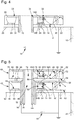
- the figure 5 is a longitudinal sectional view of a first embodiment of a set of light display needles according to the invention wherein the respective light sources are connected in parallel.
- the set of needles comprises a first and a second illuminated display needle, respectively 38 and 40. It should be understood that these first and second illuminating display hands 38 and 40 have a structure similar to that of the needle of the invention. light display 1 described above in connection with the Figures 1 to 4 .
- the first light display needle 38 comprises a light guide 42 formed of an annular element 44 extended by a substantially straight portion 46.
- the annular element 44 has at its center a hole 48 for the passage of a drive shaft 50.
- a housing 52 intended to house a first light source 54 such as a light-emitting diode is formed in the annular portion 44 of the light guide 42, in the region where the rectilinear portion 46 is connected to this annular portion 44.
- the first light source 54 includes first and second poles 54A and 54B for its electrical connection to a source power supply 56 in electrical energy housed inside a frame 58, for example a wristwatch equipped with the set of luminous display needles according to the invention.
- the power source 56 in electrical energy referred to herein is of the same type as the power source 16 described above in connection with the figure 4 .
- the light guide 42 has a first surface portion 60 directed towards an observer, and a second surface portion 62 opposite the first surface portion 60.
- An annular electrically conductive support piece 64 carries the first light source 54. This support piece 64 is fixed in a circular groove 66 formed in the base of the annular element 44.
- the second light display needle 40 comprises a light guide 68 formed of an annular element 70 extended by a substantially straight portion 72.
- the annular element 70 has at its center a hole 74 for the passage of a drive shaft 76.
- a housing 78 for accommodating a second light source 80 such as a light-emitting diode is formed in the annular portion 70 of the light guide 68, in the region where the rectilinear portion 72 is connected to this annular portion 70.
- the second light source 80 includes first and second poles 80A and 80B for its electrical connection to the power source 56 in electrical energy housed inside the frame 58, for example a wristwatch equipped with the set of luminous display needles according to the invention.
- first and second light sources 54 and 80 are of the same type as the light source 14 described above in connection with the figure 4
- the light guide 68 is provided with a first surface portion 82 directed towards an observer, and a second surface portion 84 opposed to the first surface portion 82.
- An electrically conductive support piece 86 in the form of a ring carries the second light source 80. This support piece 86 is fixed in a circular groove 88 formed in the base of the annular element 70.
- the driving axis 76 of the second light-indicator needle 40 is concentrically arranged inside the drive shaft 50 of the first light-indicator needle 38, with the interposition of an insulating layer 90 between the two drive shafts 50 and 76.
- the first pole 54A of the first light source 54 is connected to the power source 56 via the electrically conductive covering piece 32 disposed on the first surface portion 60 of the light guide 42 and in electrical contact with the axis
- the second pole 54B of the first light source 54 is connected to the power source 56 via the frame 58 of the portable object.
- the second pole 54B of the first light source 54 is connected to the frame 58 of the portable object and, consequently, to the power source 56 in electrical energy via the electrically conductive support piece 64.
- the electrical connection between the support piece 64 and a frame member 58 of the portable object such as a dial 92 above which the light display needle 38 moves. according to the invention is done through an electrically conductive friction piece 94.
- the first pole 80A of the second light source 80 is connected to the first pole 54A of the first light source 54, and the second pole 80B of the second light source 80 is connected to the frame 58 of the portable object. More specifically, the first pole 80A of the second light source 80 is connected to the first pole 54A of the first light source 54 by friction contact 96 between the first and the second light needle 38, 40.
- the second pole 80B of the second light source 80 is connected to the frame 58 of the portable object via the electrically conductive covering piece 32 formed on the first surface portion 82 of the light guide 68 and in electrical contact with the axis drive 76 of the second light needle 40.
- the frame 58 is connected to a ground and the first pole 54A of the first light source 54 is connected to the positive terminal of the source power supply 56.
- the figure 6 is a schematic representation of an alternative embodiment of the set of luminous display needles according to the invention wherein the light sources are connected in parallel at the end of the needle.
- the first and second light sources 54 and 80 mounted adjacent the free end of the first and second light display hands 38 and 40, are connected in parallel across the power source. 56 in power supply.
- the second pole 80B of the second light source 80 is connected to the frame 58 of the portable object via the drive axis 76 of the second light needle 40.
- the electrical connection between the second pole 80B of the second light source 80 and the driving axis 76 is provided by the electrically conductive covering member 32 formed on the first surface portion 82 of the second light display pin 40.
- An electrically conductive track 98 is formed on the second surface portion 84 for the electrical connection between the first pole 80A of the second light source 80 and the first pole 54A of the first light source 54 via the electrically conductive friction piece 96 and the dressing part 32 formed on the first surface portion 60 of the first light display needle 38.
- the trim piece 32 is in electrical contact with the drive shaft 50 of the first guille 38.
- the conductive track 98 is not in contact with the driving axis 76 of the second light-indicator needle 40.
- An electrically conductive track 100 is formed on the second surface portion 62 of the first display needle 38 to ensure, via the friction piece 94, the electrical connection between the second pole 54B of the first light source 54 and a frame member 58 of the portable object such as the dial 92.
- the conductive track 100 is not in contact with the drive shaft 50 of the first display hand
- the frame 58 is connected to a ground and the drive axis 50 of the first light needle 40 is connected to the positive terminal of the power source 56.
- the electrical contact provided by the friction piece 96 can be further improved by using an electrically conductive lubricating agent such as graphite.
- the figure 7 is a longitudinal sectional view of a second embodiment of a set of luminous display hands according to the invention in which the respective light sources are connected in series.
- the second pole 54B of the first light source 54 is connected to the power source 56 via the frame 58 of the portable object.
- the electrical connection between the support piece 64 and an element of the frame 58 of the portable object such as the dial 92 above which the luminous display needle 38 moves according to the invention is via the friction piece 94 electrically conductive.
- the first pole 54A of the first light source 54 is connected to the second pole 80B of the second light source 80 by friction contact 96 between the first and the second light needle 38, 40. More specifically, the first pole 54A of the first light source 54 is in contact with a ring-shaped metallization 102 formed in the first surface portion 60 of the light guide 42 directed towards the observer.
- This metallization 102 is electrically connected with the second pole 80B of the second light source 80 via the friction piece 96 electrically conductive.
- the first pole 80A of the second light source 80 is connected to the power source 56 via the drive shaft 76 of the second light display needle 40.
- the first pole 80A of the second source light 80 is in contact with a ring-shaped metallization 104 formed in the first surface portion 82 of the light guide 68 directed towards the observer.
- This metallization 104 is in turn connected to the drive axis 76, for example by means of an electrical connection wire 106.
- the frame 58 is connected to a ground and the drive axis 76 is connected to the positive terminal of the power source 56.
- the drive axis 50 of the first light display needle 38 does not role in the electrical connection of the first and second light sources 54 and 80. Therefore, the drive shaft 50 can be made indifferently in an insulating material or conductor of electricity. Furthermore, it is not essential to interpose an insulating layer between the two drive shafts 50 and 76. The only precaution to be taken is to ensure that the support part 64 and the metallization 102 are not in contact with the drive shaft 50 in the case where the latter is electrically conductive.
- the figure 8 is a longitudinal sectional view of a first embodiment of the set of luminous display hands in which the respective light sources are connected in series.
- the drive shaft 50 of the first light display needle 38 is connected to the power source 56 via the frame 58 of the portable object.
- the electrical connection between the drive shaft 50 and a frame member 58 of the portable object is via an electrically conductive friction piece 108.
- the electrical connection between the second pole 54B of the first light source 54 and the power source 56 in electrical energy is through a metallization 110 which electrically connects the support member 64 to the drive shaft 50.
- the connection between the first pole 54A of the first light source 54 and the second pole 80B of the second light source 80, and the electrical connection between the first pole 80A of the second light source 80 and the drive shaft 76 the second light display needle 40 remain unchanged from what has been described in figure 6 .
- an insulating layer 90 is interposed between the two drive axes 50 and 76.
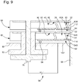
- the figure 9 is a schematic representation of a second embodiment of the set of light display needles according to the invention wherein the light sources are connected in series at the end of the needle.
- the first and second light sources 54 and 80 mounted in the vicinity of the free end of the first and second light display hands 38 and 40, are connected in series to the terminals of the source of light.
- power supply 56 in power supply.
- the first pole 80A of the second light source 80 is connected to the frame 58 of the portable object via the drive axis 76 of the second light needle 40.
- the electrical connection between the first pole 80A of the second light source 80 and the driving axis 76 is provided by the electrically conductive covering member 32 formed on the first surface portion 82 of the second light-indicator needle 40.
- An electrically conductive track 112 is arranged on the second surface portion 84 for the electrical connection between the second pole 80B of the second light source 80 and the first pole 54A of the first light source 54 via the friction piece 96 and the trim piece 32 on the first surface portion 60 of the first light display needle 38.
- An electrically conductive track 114 is provided on the second surface portion 62 of the first display hand. age 38 to ensure, via the friction piece 94, the electrical connection between the second pole 54B of the first light source 54 and a frame member 58 of the portable object such as the dial 92.
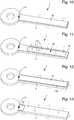
- the width of the light guide 2 is equal to or less than the width of the trim piece 32.
- an opening 98 made in the trim piece 32 shows the light guide 2 which is provided in its visible part microstructures 116 which allow to extract the light and thus illuminate the needle.
- the light guide 2 is made of an intrinsically diffusing material which spontaneously produces optical losses throughout the volume of the material.
- the covering piece 32 is narrower than the light guide 2 and the edge of the light guide 2 has a prismatic shape 118 which deflects the light towards the user.
- the trim piece 32 stops at the annular portion 4 of the light guide 2 and light extraction techniques similar to those described above are used.
- the present invention is not limited to the embodiments which have just been described and that various modifications and simple variants can be envisaged by those skilled in the art without departing from the scope of the invention as defined by the appended claims.
- the diameter of the hole 8 pierced in the annular element 4 for the passage of the drive shaft 10 has a diameter slightly greater than that of the drive shaft 10.
- the drive shaft 10 has a certain elasticity, otherwise the drive shaft 10 does not deform sufficiently during hunting and risk breaking.
- the dimensions of the light source 14 must be such that once placed in its housing 12, the light source 14 comes into electrical contact with the trim piece 32.
- the smaller the dimensions of the light source 14 the more the light display needle according to the invention can be thin.
- the light sources are mounted at the end of the needle can be advantageously used needles, for example metal, conventional type. In this case, it is not necessary for the light to propagate in a light guide to allow illumination of the needle.
- the light sources, mounted at the end of the needles on the upper surface thereof can emit light towards the user. They can also be mounted at the end of the needles, so as to emit light in the extension thereof, which allows to illuminate for example a flange which surrounds the dial above which the needles d luminous display according to the invention.
- the light sources can also be mounted on the back side of the hands, so as to illuminate the dial.
- light sources emit light in the opposite direction to the usual direction of needle rotation.
- different colored light sources for each of the luminous display hands.
- Light sources of a first color will emit light in a first mode of operation, for example in display setting mode, and light sources of a second color will emit light in normal operation mode needles, for example in the current time display mode.
Description
La présente invention concerne un jeu d'aiguilles d'affichage lumineuses pour un objet portable. La présente invention concerne en particulier un jeu d'aiguilles d'affichage lumineuses pour une pièce d'horlogerie telle qu'une montre-bracelet ou un appareil de mesure à affichage analogique.The present invention relates to a set of illuminated display needles for a portable object. In particular, the present invention relates to a set of illuminated display hands for a timepiece such as a wristwatch or an analog display meter.
Les aiguilles de montre sont fabriquées avec des tolérances serrées. Le trou de l'aiguille pour le passage du canon est en général réalisé avec des précisions de l'ordre du micromètre. Cette précision est nécessaire pour pouvoir garantir un chassage correct de l'aiguille sur son axe. Les aiguilles sont en général réalisées à partir d'une feuille métallique dont l'épaisseur n'excède pas quelques centaines de micromètre. Pour réduire l'épaisseur de la montre, la distance entre les aiguilles et la glace de la montre n'excède habituellement pas un millimètre, tandis que la distance qui sépare deux aiguilles coaxiales, par exemple l'aiguille des heures et celle des minutes, est de l'ordre d'une fraction de millimètre.The watch hands are manufactured with close tolerances. The hole of the needle for the passage of the barrel is generally made with accuracies of the order of a micrometer. This precision is necessary to be able to guarantee a correct hunting of the needle on its axis. The needles are generally made from a metal sheet whose thickness does not exceed a few hundred microns. To reduce the thickness of the watch, the distance between the hands and the ice of the watch does not usually exceed one millimeter, while the distance between two coaxial needles, for example the hour hand and the minute hand, is of the order of a fraction of a millimeter.
Les aiguilles d'une montre jouent bien sûr un rôle fonctionnel, par exemple indiquer l'heure courante, mais elles jouent également un rôle décoratif en contribuant largement à l'aspect esthétique de la montre qu'elles équipent. A cet effet, les aiguilles doivent répondre à des critères stricts. Une technique bien connue dans le monde horloger pour permettre aux aiguilles d'être visibles dans le noir consiste à revêtir la surface des aiguilles orientée du côté de l'utilisateur d'une couche de matériau phosphorescent. Un exemple d'un tel matériau est un pigment photoluminescent non radioactif commercialisé par la société japonaise Nemoto & Co., Ltd. sous la marque enregistrée Super-Luminova®. Ce pigment peut aussi être utilisé pour revêtir les index horaires du cadran de la montre. De jour, la couche de matériau phosphorescent absorbe l'énergie lumineuse. Cette énergie lumineuse est ensuite restituée de nuit par la couche de matériau phosphorescent sous forme de rayonnement lumineux. Cette technique d'illumination des aiguilles d'une montre est assez commode dans la mesure où le fonctionnement de la couche de matériau phosphorescent est totalement passif et ne nécessite donc, pour son fonctionnement, l'actionnement d'aucun dispositif mécanique ou électrique, ni prélèvement d'énergie qui serait fournie par la montre. Cette technique d'illumination des aiguilles d'une montre présente toutefois également certains inconvénients au premier rang desquels on peut citer le fait que la couche de matériau phosphorescent nécessite d'être préalablement éclairée par une source de lumière avant de pouvoir émettre de l'énergie lumineuse. De même, le phénomène de réémission de lumière par effet de phosphorescence est limité dans le temps, de sorte qu'au fur et à mesure que la couche phosphorescente relâche l'énergie lumineuse qu'elle a stockée, sa luminosité décroît. Les aiguilles revêtues d'une couche de matériau phosphorescent n'ont donc pas un aspect constant. Enfin, la gamme de matériaux phosphorescents disponibles sur le marché est limitée, de sorte que la plupart des montres dans lesquelles de tels matériaux sont utilisés finissent par avoir le même aspect dans l'obscurité et même en plein jour.The needles of a watch play of course a functional role, for example to indicate the current time, but they also play a decorative role contributing largely to the aesthetic aspect of the watch they equip. For this purpose, needles must meet strict criteria. A technique well known in the world of watchmaking to allow needles to be visible in the dark is to coat the surface of needles oriented towards the user side of a layer of phosphorescent material. An example of such a material is a non-radioactive photoluminescent pigment marketed by the Japanese company Nemoto & Co., Ltd. under the registered trademark Super-Luminova®. This pigment can also be used to coat the hour markers of the watch face. By day, the layer of phosphorescent material absorbs light energy. This light energy is then restored at night by the layer of phosphorescent material in the form of light radiation. This clockwise illumination technique is quite convenient insofar as the operation of the layer of phosphorescent material is totally passive and therefore does not require, for its operation, the actuation of any mechanical or electrical device, or energy levy that would be provided by the watch. This clockwise illumination technique, however, also has certain disadvantages, the first of which is the fact that the layer of phosphorescent material needs to be previously illuminated by a light source before being able to emit energy. light. Likewise, the phenomenon of phosphorescent light re-emission is limited in time, so that as the phosphorescent layer releases the light energy that it has stored, its luminosity decreases. The needles coated with a layer of phosphorescent material therefore do not have a constant appearance. Finally, the range of phosphorescent materials available on the market is limited, so that most watches in which such materials are used end up having the same appearance in the dark and even in daylight.
A titre de variante de la couche phosphorescente, on peut envisager d'utiliser des techniques d'illumination actives dans lesquelles des sources de lumière discrètes sont utilisées pour éclairer les aiguilles d'une montre. A titre d'exemple, il est possible d'intégrer dans la montre une source de lumière ultraviolette, de façon que la radiation émise vienne exciter la matière fluorescente qui recouvre les aiguilles. Un tel mode de réalisation présente cependant également des inconvénients. D'une part, les sources de lumière ultraviolettes, également appelées sources de lumière noire, émettent une certaine quantité de lumière visible, de sorte que l'utilisateur est susceptible de percevoir un halo de lumière à l'endroit où la source de lumière est implantée. D'autre part, étant donné que les aiguilles sont mobiles par rapport à la source de lumière ultraviolette, elles ne reçoivent pas toujours la même quantité de lumière ultraviolette, de sorte que leur luminosité peut varier.As a variant of the phosphorescent layer, it is possible to envisage using active illumination techniques in which discrete light sources are used to illuminate the needles of a watch. For example, it is possible to integrate in the watch a source of ultraviolet light, so that the emitted radiation excite the fluorescent material that covers the needles. Such an embodiment however, also has disadvantages. On the one hand, ultraviolet light sources, also known as black light sources, emit a certain amount of visible light, so that the user is likely to perceive a halo of light at the point where the light source is implanted. On the other hand, since the needles are movable relative to the ultraviolet light source, they do not always receive the same amount of ultraviolet light, so that their brightness may vary.
Les documents
La présente invention a pour but de remédier aux inconvénients susmentionnés ainsi qu'à d'autres encore en procurant un jeu d'aiguilles d'affichage lumineuses pouvant être illuminées à la demande de l'utilisateur, selon une grande variété de couleurs et en respectant les contraintes dimensionnelles et esthétiques auxquelles elle est soumise.The object of the present invention is to overcome the aforementioned and other disadvantages by providing a set of illuminated display needles which can be illuminated at the request of the user, in a wide variety of colors and in accordance with the dimensional and aesthetic constraints to which it is subjected.
A cet effet, la présente invention concerne un jeu d'aiguilles d'affichage lumineuses pour un objet selon les revendications indépendantes 1 et 6.For this purpose, the present invention relates to a set of luminous display hands for an object according to
Grâce à ces caractéristiques, la présente invention procure un jeu d'aiguilles montées concentriquement et qui possèdent chacune une source de lumière pour leur illumination. Ce résultat remarquable est atteint grâce au fait que l'un des pôles de l'une des sources de lumière est relié à l'un des pôles de l'autre source de lumière grâce au contact électrique entre les deux aiguilles, ce qui permet d'utiliser les axes d'entraînement des deux aiguilles pour la connexion électrique des sources de lumière aux bornes de la source d'alimentation. Par ailleurs, du fait que l'on utilise les aiguilles pour l'acheminement du signal électrique, on obtient un montage d'une grande simplicité qui est donc moins onéreux et plus fiable.With these features, the present invention provides a set of concentrically mounted needles each having a light source for illumination thereof. This remarkable result is achieved thanks to the fact that one of the poles of one of the light sources is connected to one of the poles of the other light source thanks to the electrical contact between the two needles, which allows to use the drive shafts of the two needles for the electrical connection of the light sources to the terminals of the power source. Moreover, because the needles are used for conveying the electrical signal, a simplicity of assembly is obtained which is therefore less expensive and more reliable.
Selon une caractéristique complémentaire de l'invention, le premier pôle de la seconde source de lumière est relié au premier pôle de la première source de lumière par contact de frottement entre la première et la seconde aiguille lumineuse.According to a complementary feature of the invention, the first pole of the second light source is connected to the first pole of the first light source by frictional contact between the first and the second light needle.
Selon une autre caractéristique de l'invention, la première aiguille d'affichage lumineuse comprend un guide de lumière muni d'un élément annulaire dans lequel est percé le trou pour le passage de l'axe d'entraînement de la première aiguille d'affichage lumineuse, et la seconde aiguille d'affichage lumineuse comprend un guide de lumière muni d'un élément annulaire dans lequel est percé le trou pour le passage de l'axe d'entraînement de la seconde aiguille d'affichage lumineuse, le contact entre la première et la seconde aiguille lumineuse s'opérant par frottement entre les deux éléments annulaires.According to another characteristic of the invention, the first luminous display needle comprises a light guide provided with an annular element in which is drilled the hole for the passage of the drive shaft of the first display needle light, and the second light-indicator needle comprises a light guide provided with an annular element in which is drilled the hole for the passage of the drive shaft of the second light-indicator needle, the contact between the first and second light needle operating by friction between the two annular elements.
Du fait que le contact électrique entre les deux aiguilles d'affichage lumineuses s'opère par frottement entre les deux éléments annulaires, le contact électrique entre les deux aiguilles n'est jamais rompu et ce quelle que soit la position relative des deux aiguilles.Since the electrical contact between the two luminous display hands is effected by friction between the two annular elements, the electrical contact between the two hands is never broken, whatever the relative position of the two hands.
D'autres caractéristiques et avantages de l'invention ressortiront plus clairement de la description détaillée qui suit d'un mode de réalisation de l'invention, cet exemple étant donné à titre purement illustratif et non limitatif seulement en liaison avec le dessin annexé sur lequel :
- la
figure 1 est une vue de dessus d'une aiguille d'affichage lumineuse ; - la
figure 2 est une vue en coupe selon la ligne II-II de lafigure 1 d'une aiguille d'affichage lumineuse ; - la
figure 3 est une vue en perspective d'une pièce support électriquement conductrice qui porte la source de lumière ; - la
figure 4 est une vue analogue à celle de lafigure 2 et montre l'intégration de la source de lumière dans le guide de lumière ; - la
figure 5 est une vue en coupe longitudinale d'un premier mode de réalisation d'un jeu d'aiguilles d'affichage lumineuses selon l'invention dans lequel les sources de lumière respectives sont montées en parallèle ; - la
figure 6 est une représentation schématique d'une variante de réalisation du jeu d'aiguilles d'affichage lumineuses selon l'invention dans laquelle les sources de lumière sont montées en parallèle en bout d'aiguille ; - la
figure 7 est une vue en coupe longitudinale d'un second mode de réalisation d'un jeu d'aiguilles d'affichage lumineuses selon l'invention dans lequel les sources de lumière respectives sont montées en série ; - la
figure 8 est une vue en coupe longitudinale d'une première variante de réalisation du jeu d'aiguilles d'affichage lumineuses dans laquelle les sources de lumière respectives sont montées en série ; - la
figure 9 est une représentation schématique d'une seconde variante de réalisation du jeu d'aiguilles d'affichage lumineuses selon l'invention dans laquelle les sources de lumière sont montées en série en bout d'aiguille, et - les
figures 10 à 13 sont des vues de dessus de divers modes de réalisation d'une aiguille d'affichage lumineuse selon l'invention.
- the
figure 1 is a top view of a luminous display needle; - the
figure 2 is a sectional view along line II-II of thefigure 1 a luminous display needle; - the
figure 3 is a perspective view of an electrically conductive support piece which carries the light source; - the
figure 4 is a view similar to that of thefigure 2 and shows the integration of the light source into the light guide; - the
figure 5 is a longitudinal sectional view of a first embodiment of a set of light display needles according to the invention wherein the respective light sources are connected in parallel; - the
figure 6 is a schematic representation of an alternative embodiment of the set of light display needles according to the invention wherein the light sources are connected in parallel at the end of the needle; - the
figure 7 is a longitudinal sectional view of a second embodiment of a set of light display needles according to the invention wherein the respective light sources are connected in series; - the
figure 8 is a longitudinal sectional view of a first embodiment of the set of luminous display hands in which the respective light sources are connected in series; - the
figure 9 is a schematic representation of a second variant embodiment of the set of luminous display needles according to the invention in which the light sources are connected in series at the end of the needle, and - the
Figures 10 to 13 are top views of various embodiments of a light display pointer according to the invention.
La présente invention procède de l'idée générale inventive qui consiste à éclairer un jeu d'aiguilles d'affichage lumineuses pour un objet portable tel qu'une montre-bracelet ou bien un instrument de mesure au moyen d'une source de lumière de type ponctuel, préférentiellement une diode électroluminescente. Un tel jeu d'aiguilles lumineuses d'affichage présente plusieurs avantages : son aspect ne s'altère pas avec le temps qui s'écoule et, en raison de la large gamme de diodes électroluminescentes existantes, il est possible de personnaliser l'aspect des aiguilles et donc l'aspect de l'objet portable qui en est équipé, ce qui permet de se distinguer de la concurrence. Par ailleurs, selon un autre avantage de l'invention, la source de lumière est logée dans le guide de lumière et non pas, par exemple, dans l'axe d'entraînement des aiguilles, ce qui simplifie considérablement la conception de telles aiguilles de même que leur branchement électrique à la source d'énergie électrique logée dans le bâti de l'objet portable.The present invention proceeds from the general inventive idea of illuminating a set of luminous display needles for a portable object such as a wristwatch or a measuring instrument by means of a light source of the same type. punctual, preferably an electroluminescent diode. Such a set of luminous display needles has several advantages: its appearance does not deteriorate with the passage of time and, because of the wide range of existing light-emitting diodes, it is possible to customize the appearance of needles and thus the appearance of the portable object that is equipped, which makes it possible to distinguish oneself from the competition. Furthermore, according to another advantage of the invention, the light source is housed in the light guide and not, for example, in the axis of driving the needles, which greatly simplifies the design of such needles of same as their electrical connection to the source of electrical energy housed in the frame of the portable object.
Les
Comme on l'observe sur les
La
La
La
La première aiguille d'affichage lumineuse 38 comprend un guide de lumière 42 formé d'un élément annulaire 44 prolongé par une partie 46 sensiblement rectiligne. L'élément annulaire 44 présente en son centre un trou 48 pour le passage d'un axe d'entraînement 50. Un logement 52 destiné à héberger une première source de lumière 54 telle qu'une diode électroluminescente est ménagé dans la partie annulaire 44 du guide de lumière 42, dans la zone où la partie rectiligne 46 se raccorde à cette partie annulaire 44. La première source de lumière 54 comprend des premier et second pôles 54A et 54B pour sa connexion électrique à une source d'alimentation 56 en énergie électrique logée à l'intérieur d'un bâti 58 par exemple d'une montre-bracelet équipée du jeu d'aiguilles d'affichage lumineuses selon l'invention. On notera que la source d'alimentation 56 en énergie électrique dont il est question ici est du même type que la source d'alimentation 16 décrite ci-dessus en liaison avec la
Une pièce support 64 électriquement conductrice en forme d'anneau porte la première source de lumière 54. Cette pièce support 64 est fixée dans une rainure circulaire 66 ménagée dans la base de l'élément annulaire 44.An annular electrically
La seconde aiguille d'affichage lumineuse 40 comprend un guide de lumière 68 formé d'un élément annulaire 70 prolongé par une partie 72 sensiblement rectiligne. L'élément annulaire 70 présente en son centre un trou 74 pour le passage d'un axe d'entraînement 76. Un logement 78 destiné à héberger une seconde source de lumière 80 telle qu'une diode électroluminescente est ménagé dans la partie annulaire 70 du guide de lumière 68, dans la zone où la partie rectiligne 72 se raccorde à cette partie annulaire 70. La seconde source de lumière 80 comprend des premier et second pôles 80A et 80B pour sa connexion électrique à la source d'alimentation 56 en énergie électrique logée à l'intérieur du bâti 58 par exemple d'une montre-bracelet équipée du jeu d'aiguilles d'affichage lumineuses selon l'invention. On notera que les première et seconde sources de lumière 54 et 80 sont du même type que la source de lumière 14 décrite ci-avant en liaison avec la
Une pièce support 86 électriquement conductrice en forme d'anneau porte la seconde source de lumière 80. Cette pièce support 86 est fixée dans une rainure circulaire 88 ménagée dans la base de l'élément annulaire 70.An electrically
L'axe d'entraînement 76 de la seconde aiguille d'affichage lumineuse 40 est disposé concentriquement à l'intérieur de l'axe d'entraînement 50 de la première aiguille d'affichage lumineuse 38, avec interposition d'une couche isolante 90 entre les deux axes d'entraînement 50 et 76.The driving
Le premier pôle 54A de la première source de lumière 54 est relié à la source d'alimentation 56 via la pièce d'habillage 32 électriquement conductrice disposée sur la première portion de surface 60 du guide de lumière 42 et en contact électrique avec l'axe d'entraînement 50 de la première aiguille 38. Le second pôle 54B de la première source de lumière 54 est relié à la source d'alimentation 56 via le bâti 58 de l'objet portable. Le second pôle 54B de la première source de lumière 54 est relié au bâti 58 de l'objet portable et, par suite, à la source d'alimentation 56 en énergie électrique via la pièce support 64 électriquement conductrice. A titre d'exemple illustratif et non limitatif seulement, la connexion électrique entre la pièce support 64 et un élément du bâti 58 de l'objet portable tel qu'un cadran 92 au-dessus duquel se déplace l'aiguille d'affichage lumineuse 38 selon l'invention se fait par l'intermédiaire d'une pièce de frottement 94 électriquement conductrice.The
Le premier pôle 80A de la seconde source de lumière 80 est relié au premier pôle 54A de la première source de lumière 54, et le second pôle 80B de la seconde source de lumière 80 est relié au bâti 58 de l'objet portable. Plus précisément, le premier pôle 80A de la seconde source de lumière 80 est relié au premier pôle 54A de la première source de lumière 54 par contact de frottement 96 entre la première et la seconde aiguille lumineuse 38, 40. Le second pôle 80B de la seconde source de lumière 80 est relié au bâti 58 de l'objet portable via la pièce d'habillage 32 électriquement conductrice ménagée sur la première portion de surface 82 du guide de lumière 68 et en contact électrique avec l'axe d'entraînement 76 de la seconde aiguille lumineuse 40. A titre d'exemple préféré mais non limitatif, le bâti 58 est relié à une masse et le premier pôle 54A de la première source de lumière 54 est relié à la borne positive de la source d'alimentation 56.The
Dans ce qui suit, les éléments identiques à ceux décrits en liaison avec la
La
La
Le second pôle 54B de la première source de lumière 54 est relié à la source d'alimentation 56 via le bâti 58 de l'objet portable. A titre d'exemple, la connexion électrique entre la pièce support 64 et un élément du bâti 58 de l'objet portable tel que le cadran 92 au-dessus duquel se déplace l'aiguille d'affichage lumineuse 38 selon l'invention se fait par l'intermédiaire de la pièce de frottement 94 électriquement conductrice. Le premier pôle 54A de la première source de lumière 54 est relié au second pôle 80B de la seconde source de lumière 80 par contact de frottement 96 entre la première et la seconde aiguille lumineuse 38, 40. Plus précisément, le premier pôle 54A de la première source de lumière 54 est en contact avec une métallisation 102 en forme d'anneau ménagée dans la première portion de surface 60 du guide de lumière 42 dirigée du côté de l'observateur. Cette métallisation 102 est reliée électriquement avec le second pôle 80B de la seconde source de lumière 80 par l'intermédiaire de la pièce de frottement 96 électriquement conductrice. Le premier pôle 80A de la seconde source de lumière 80 est relié à la source d'alimentation 56 via l'axe d'entraînement 76 de la seconde aiguille d'affichage lumineuse 40. A cet effet, le premier pôle 80A de la seconde source de lumière 80 est en contact avec une métallisation 104 en forme d'anneau ménagée dans la première portion de surface 82 du guide de lumière 68 dirigée du côté de l'observateur. Cette métallisation 104 est à son tour reliée à l'axe d'entraînement 76 par exemple au moyen d'un fil de connexion électrique 106. A titre d'exemple préféré mais non limitatif, le bâti 58 est relié à une masse et l'axe d'entraînement 76 est relié à la borne positive de la source d'alimentation 56. On notera que, dans ce second mode de réalisation, l'axe d'entraînement 50 de la première aiguille d'affichage lumineuse 38 ne joue pas de rôle dans la connexion électrique des première et seconde sources de lumière 54 et 80. Par conséquent, l'axe d'entraînement 50 peut être réalisé indifféremment dans un matériau isolant ou conducteur de l'électricité. Par ailleurs, il n'est pas indispensable d'interposer une couche isolante entre les deux axes d'entraînement 50 et 76. La seule précaution à prendre est de s'assurer que la pièce support 64 et la métallisation 102 ne soient pas en contact avec l'axe d'entraînement 50 dans le cas où ce dernier est électriquement conducteur.The
La
Dans cette première variante de réalisation, l'axe d'entraînement 50 de la première aiguille d'affichage lumineuse 38 est relié à la source d'alimentation 56 via le bâti 58 de l'objet portable. A titre d'exemple, la connexion électrique entre l'axe d'entraînement 50 et un élément du bâti 58 de l'objet portable se fait par l'intermédiaire d'une pièce de frottement 108 électriquement conductrice. La connexion électrique entre le second pôle 54B de la première source de lumière 54 et la source d'alimentation 56 en énergie électrique se fait grâce à une métallisation 110 qui relie électriquement la pièce support 64 à l'axe d'entraînement 50. La connexion électrique entre le premier pôle 54A de la première source de lumière 54 et le second pôle 80B de la seconde source de lumière 80, et la connexion électrique entre le premier pôle 80A de la seconde source de lumière 80 et l'axe d'entraînement 76 de la seconde aiguille d'affichage lumineuse 40 restent inchangées par rapport à ce qui a été décrit à la
La
Dans un premier mode d'exécution de l'aiguille (
Dans un deuxième mode d'exécution de l'aiguille (
Dans un troisième mode d'exécution de l'aiguille (
Dans un quatrième mode d'exécution de l'aiguille (
Il va de soi que la présente invention n'est pas limitée aux modes de réalisation qui viennent d'être décrits et que diverses modifications et variantes simples peuvent être envisagées par l'homme du métier sans sortir du cadre de l'invention tel que défini par les revendications annexées. On comprendra notamment que le diamètre du trou 8 percé dans l'élément annulaire 4 pour le passage de l'axe d'entraînement 10 a un diamètre légèrement supérieur à celui de l'axe d'entraînement 10. En effet, pour pouvoir chasser l'aiguille d'affichage lumineuse selon l'invention sur l'axe d'entraînement 10, il faut que l'axe d'entraînement 10 présente une certaine élasticité, faute de quoi l'axe d'entraînement 10 ne se déforme pas suffisamment durant le chassage et risque de casser. De même, on comprend que les dimensions de la source de lumière 14 doivent être telles qu'une fois placée dans son logement 12, la source de lumière 14 vienne en contact électrique avec la pièce d'habillage 32. Par ailleurs, il va de soi que plus les dimensions de la source de lumière 14 sont petites, plus l'aiguille d'affichage lumineuse selon l'invention pourra être mince. On notera d'autre part que, dans le cas où les sources de lumière sont montées en bout d'aiguille, on peut avantageusement utiliser des aiguilles, par exemple métalliques, de type conventionnel. Dans ce cas, en effet, il n'est pas nécessaire que la lumière se propage dans un guide de lumière pour permettre l'éclairage de l'aiguille. Les sources de lumière, montées au bout des aiguilles sur la surface supérieure de celles-ci, peuvent émettre de la lumière en direction de l'utilisateur. Elles peuvent aussi être montées à l'extrémité des aiguilles, de manière à émettre de la lumière dans le prolongement de celles-ci, ce qui permet d'éclairer par exemple un rehaut qui entoure le cadran au-dessus duquel se déplacent les aiguilles d'affichage lumineuses selon l'invention. Les sources de lumière peuvent aussi être montées sur la face arrière des aiguilles, de manière à éclairer le cadran. Il peut aussi être envisagé que les sources de lumière émettent de la lumière dans le sens opposé au sens habituel de rotation des aiguilles. De même, il peut être envisagé d'utiliser des sources de lumière de couleurs différentes pour chacune des aiguilles d'affichage lumineuses. On peut même envisager de monter par exemple deux sources de lumière de couleurs différentes sur chacune des aiguilles. Les sources de lumière d'une première couleur émettront de la lumière dans un premier mode de fonctionnement, par exemple en mode de réglage de l'affichage, et les sources de lumière d'une seconde couleur émettront de la lumière en mode de fonctionnement normal des aiguilles, par exemple en mode d'affichage de l'heure courante.It goes without saying that the present invention is not limited to the embodiments which have just been described and that various modifications and simple variants can be envisaged by those skilled in the art without departing from the scope of the invention as defined by the appended claims. It will be understood in particular that the diameter of the
-
Aiguille d'affichage lumineuse 1
Luminous display needle 1 -
Guide de lumière 2
Light guide 2 - Elément annulaire 4Annular element 4
-
Partie rectiligne 6
Straight part 6 -
Trou 8
Hole 8 -
Axe d'entraînement 10Drive
shaft 10 -
Logement 12
Housing 12 -
Source de lumière 14
Light source 14 -
Premier et second pôles 14A, 14BFirst and
second poles -
Source d'alimentation 16
Power Source 16 -
Bâti 18
Building 18 -
Première portion de surface 20First portion of
surface 20 -
Seconde portion de surface 22Second portion of
surface 22 -
Pièce support 24
Support part 24 -
Rainure circulaire 26
Circular groove 26 -
Cadran 28
Dial 28 -
Pièce de frottement 30
Friction piece 30 -
Pièce d'habillage 32
Dressing Room 32 -
Rainure 34
Groove 34 -
Tranche 36
Tranche 36 -
Première aiguille d'affichage lumineuse 38First
light display needle 38 -
Seconde aiguille d'affichage lumineuse 40Second
light display needle 40 -
Guide de lumière 42
Light guide 42 -
Elément annulaire 44
Ring element 44 -
Partie rectiligne 46
Straight part 46 -
Trou 48
Hole 48 -
Axe d"entraînement 50
Training axis 50 -
Logement 52
Housing 52 -
Première source de lumière 54First
light source 54 -
Premier et second pôles 54A, 54BFirst and
second poles -
Source d'alimentation 56
Power Source 56 -
Bâti 58
Building 58 -
Première portion de surface 60First portion of
surface 60 -
Seconde portion de surface 62Second portion of
surface 62 -
Pièce support 64
Support part 64 -
Rainure circulaire 66
Circular groove 66 -
Guide de lumière 68
Light guide 68 -
Elément annulaire 70
Annular element 70 -
Partie rectiligne 72
Straight portion 72 -
Trou 74
Hole 74 -
Axe d'entraînement 76Drive
shaft 76 -
Logement 78
Housing 78 -
Seconde source de lumière 80Second
light source 80 -
Premier et second pôles 80A, 80BFirst and
second poles -
Première portion de surface 82First portion of
surface 82 -
Seconde portion de surface 84Second portion of
surface 84 -
Pièce support 86
Support part 86 -
Rainure circulaire 88
Circular groove 88 -
Couche isolante 90Insulating
layer 90 -
Cadran 92
Dial 92 -
Pièce de frottement 94
Friction piece 94 -
Contact de frottement 96
Friction contact 96 -
Piste électriquement conductrice 98Electrically
conductive track 98 -
Piste électriquement conductrice 100Electrically
conductive track 100 -
Métallisation 102
Metallization 102 -
Métallisation 104
Metallization 104 -
Fil de connexion électrique 106
Electrical connection wire 106 -
Pièce de frottement 108
Friction piece 108 -
Métallisation 110
Metallization 110 -
Piste électriquement conductrice 112Electrically
conductive track 112 -
Piste électriquement conductrice 114Electrically
conductive track 114 -
Microstructures 116
Microstructures 116 -
Forme prismatique 118
Prismatic shape 118
Claims (7)
- Set of luminous display hands for a portable object, the portable object including a frame (58) which houses an electrical energy supply source (56) including a first and a second terminal, the set of luminous display hands including at least a first and a second luminous display hand (38, 40) made of an electrically non-conductive material and in which a hole (48, 74) is arranged for the passage of a drive arbor (50, 76), the drive arbor (76) of the second luminous display hand (40) being arranged concentrically inside the drive arbor (50) of the first luminous display hand (38), each of the first and second luminous display hands (38, 40) carrying a first, respectively a second light source (54, 80) which emits light, the first and second light sources (54, 80) each including a first and a second pole, the light sources being mounted in parallel and the first pole (80A) of the second light source (80) being connected to the first pole (54A) of the first light source (54) by contact between the first and second luminous hands (38, 40), an electrically conductive support piece (86) which carries the second light source (80) being fixed in the base of the annular element (70) of the second luminous display hand (40) and being connected by a friction part (96) to an electrically conductive external part (32) in contact with the first pole (54A) of the first light source (54) and arranged on a first surface portion (60) of the first luminous display hand (38) facing an observer, characterized in that the first pole (54A) of the first light source (54) is connected to the energy supply source (56) via the drive arbor (50) of the first hand (38), and in that the second pole (54B) of the first light source (54) is connected to the energy supply source (56) via the frame (58) of the portable object, the first pole (80A) of the second light source (80) being connected to the first pole (54A) of the first light source (54), and the second pole (80B) of the second light source (80) being connected to the frame (58) of the portable object via the drive arbor (76) of the second luminous hand (40), an insulating layer (90) being inserted between the two drive arbors (50, 76).
- Set of luminous display hands according to claim 1, characterized in that the first pole (80A) of the second light source (80) is connected to the first pole (54A) of the first light source (54) by friction contact between the first and the second luminous hand (38, 40).
- Set of luminous display hands according to claim 2, characterized in that the first luminous display hand (38) includes a light guide (42) provided with an annular element (44) in which is made the hole (48) for the passage of the drive arbor (50) of the first luminous display hand (38), the second luminous display hand (40) including a light guide (68) provided with an annular element (70) in which is made the hole (74) for the passage of the drive arbor (76) of the second luminous display hand (40), the contact between the first and the second luminous display hands (38, 40) occurring by friction between the annular elements (44, 70).
- Set of luminous display hands according to any of claims 1 to 3, characterized in that the second pole (54B) of the first light source (54) is connected to the frame (58) of the portable object and, consequently, to the electrical energy supply source (56) via an electrically conductive support piece (64) fixed to the base of an annular element (44) via which the first luminous display hand (38) is fixed to the drive arbor (50).
- Set of luminous display hands according to claim 4, characterized in that the electrical connection between the support piece (64) and a dial (92) above which moves the first luminous display hand (38) occurs via a friction part (94).
- Set of luminous display hands for a portable object, the portable object including a frame (58) which houses an electrical energy supply source (56) including a first and a second terminal, the set of luminous display hands including at least a first and a second luminous display hand (38, 40) made of an electrically non-conductive material and in which a hole (48, 74) is arranged for the passage of a drive arbor (50, 76), the drive arbor (76) of the second luminous display hand (40) being arranged concentrically inside the drive arbor (50) of the first luminous display hand (38), each of the first and second luminous display hands (38, 40) carrying a first, respectively a second light source (54, 80) which emits light, the first and second light sources (54, 80) each including a first and a second pole, characterized in that the light sources are mounted in series and in that the second pole (80B) of the second light source (80) is connected to the first pole (54A) of the first light source (54) by contact between the first and second luminous hands (38, 40), the second pole (54B) of the first light source (54) being connected to the energy supply source (56) via the frame (58) of the portable object, the first pole (54A) of the first light source (54) being connected to the second pole (80B) of the second light source (80), and the first pole (80A) of the second light source (80) being connected to the energy supply source (56) via the drive arbor (76) of the second hand (40).
- Set of luminous display hands according to any of claims 1 to 6, characterized in that at least one of light sources (54, 80) is mounted at the tip of the corresponding luminous display hand.
Priority Applications (6)
| Application Number | Priority Date | Filing Date | Title |
|---|---|---|---|
| EP14170035.1A EP2950166B1 (en) | 2014-05-27 | 2014-05-27 | Set of luminous display hands for a portable object such as a watch or a measuring instrument |
| US14/717,392 US9588493B2 (en) | 2014-05-27 | 2015-05-20 | Set of luminous display hands for a portable object such as a watch or a measuring instrument |
| JP2015102476A JP6018666B2 (en) | 2014-05-27 | 2015-05-20 | A set of luminous indicator hands for portable items such as portable watches or measuring instruments |
| KR1020150073039A KR101710785B1 (en) | 2014-05-27 | 2015-05-26 | Set of luminous display hands for a portable object such as a watch or a measuring instrument |
| CN201510276026.3A CN105278313B (en) | 2014-05-27 | 2015-05-26 | One group of luminescence display pointer for the portable object of such as wrist-watch or measuring instrument |
| HK16108858.6A HK1220780A1 (en) | 2014-05-27 | 2016-07-25 | Set of luminous display hands for a portable object such as a watch or a measuring instrument |
Applications Claiming Priority (1)
| Application Number | Priority Date | Filing Date | Title |
|---|---|---|---|
| EP14170035.1A EP2950166B1 (en) | 2014-05-27 | 2014-05-27 | Set of luminous display hands for a portable object such as a watch or a measuring instrument |
Publications (2)
| Publication Number | Publication Date |
|---|---|
| EP2950166A1 EP2950166A1 (en) | 2015-12-02 |
| EP2950166B1 true EP2950166B1 (en) | 2019-02-20 |
Family
ID=50774771
Family Applications (1)
| Application Number | Title | Priority Date | Filing Date |
|---|---|---|---|
| EP14170035.1A Active EP2950166B1 (en) | 2014-05-27 | 2014-05-27 | Set of luminous display hands for a portable object such as a watch or a measuring instrument |
Country Status (6)
| Country | Link |
|---|---|
| US (1) | US9588493B2 (en) |
| EP (1) | EP2950166B1 (en) |
| JP (1) | JP6018666B2 (en) |
| KR (1) | KR101710785B1 (en) |
| CN (1) | CN105278313B (en) |
| HK (1) | HK1220780A1 (en) |
Families Citing this family (8)
| Publication number | Priority date | Publication date | Assignee | Title |
|---|---|---|---|---|
| JP1585242S (en) * | 2016-10-20 | 2017-09-04 | ||
| DE102017201676B4 (en) * | 2017-02-02 | 2019-08-14 | Realization Desal Ag | Watch glass with luminescent element |
| EP3447590B1 (en) | 2017-08-21 | 2020-07-22 | The Swatch Group Research and Development Ltd | Holographic display device |
| EP3572886B1 (en) * | 2018-05-23 | 2021-07-14 | The Swatch Group Research and Development Ltd | Watch comprising an element having a lighting index |
| EP3667436B1 (en) * | 2018-12-14 | 2022-05-04 | The Swatch Group Research and Development Ltd | Timepiece including a mobile element provided with a light spot |
| IT201900015252A1 (en) * | 2019-08-30 | 2021-03-02 | Giorgio Stimamiglio | WRISTWATCH WITH TIME MARKER ILLUMINATION DEVICE |
| EP3845974B1 (en) | 2019-12-31 | 2024-02-21 | The Swatch Group Research and Development Ltd | Mobile indicator for an analogue display device |
| CN116601568A (en) * | 2020-12-11 | 2023-08-15 | 斯沃奇集团研究及开发有限公司 | Method for producing luminous pointer |
Family Cites Families (23)
| Publication number | Priority date | Publication date | Assignee | Title |
|---|---|---|---|---|
| US2212359A (en) * | 1938-10-28 | 1940-08-20 | Wilcox Roy Milton | Illuminated clock |
| US2363763A (en) * | 1943-09-27 | 1944-11-28 | Howard D Werts | Clock |
| US2655783A (en) * | 1949-09-26 | 1953-10-20 | Uschkamp Walter | Luminous clock with neon-illumination of dial and hands |
| US3079748A (en) * | 1960-06-27 | 1963-03-05 | Sylvania Electric Prod | Illuminated electronic time piece |
| DE3930329C2 (en) * | 1988-09-19 | 1994-09-01 | Seikosha Kk | Arrangement for power supply for a pointer provided with a lighting element |
| JPH02179493A (en) * | 1988-12-29 | 1990-07-12 | Seikosha Co Ltd | Power supply apparatus for loaded hand |
| JPH0326987A (en) * | 1989-06-26 | 1991-02-05 | Seikosha Co Ltd | Power supply apparatus of light emitting hand of clock |
| CN2103154U (en) * | 1991-11-05 | 1992-04-29 | 赵新 | Luminous quartz clock |
| JP2579453Y2 (en) * | 1992-08-20 | 1998-08-27 | セイコープレシジョン株式会社 | LED light emitting needle |
| JPH0752627Y2 (en) * | 1994-01-20 | 1995-11-29 | 株式会社精工舎 | Luminous second hand power supply device |
| JP2799957B2 (en) * | 1994-10-27 | 1998-09-21 | セイコークロック株式会社 | EL emitting needle |
| US5697322A (en) | 1996-01-30 | 1997-12-16 | Durel Corporation | Analog display having electroluminescent pointer |
| US5797345A (en) * | 1996-11-13 | 1998-08-25 | Ford Global Technologies, Inc. | Illuminated pointer for instrument gage |
| US5751662A (en) * | 1997-01-28 | 1998-05-12 | Shaw; Sen-Yen | Illuminating timepiece |
| CN2296538Y (en) * | 1997-04-07 | 1998-11-04 | 刘洪声 | Mechanical driving clock of electro-optical display |
| US6999383B1 (en) * | 2004-08-03 | 2006-02-14 | Chine-Fu Wang | Clock with luminous hands |
| US7172302B1 (en) * | 2004-09-08 | 2007-02-06 | Timex Group B.V. | Electronic device with UV illumination arrangement |
| GB2421809A (en) * | 2004-12-29 | 2006-07-05 | Stanley Kuo | Electric Power Supply Mechanism on Spinning Indicators such as hands for timepieces. |
| US7903503B2 (en) * | 2007-10-02 | 2011-03-08 | James Brewster Olmes | Dual illumination watch face, and associated methods |
| EP2290478A1 (en) * | 2009-09-01 | 2011-03-02 | ETA SA Manufacture Horlogère Suisse | Covering element for a wristwatch |
| US20110280110A1 (en) * | 2010-05-13 | 2011-11-17 | Ming-Hsien Chen | Indicator timepiece having light diffusing effect |
| US8714762B2 (en) * | 2011-05-03 | 2014-05-06 | Zhou Cai | LED light source and manufacturing method thereof |
| JP6094025B2 (en) * | 2011-09-30 | 2017-03-15 | カシオ計算機株式会社 | Pointer illumination device |
-
2014
- 2014-05-27 EP EP14170035.1A patent/EP2950166B1/en active Active
-
2015
- 2015-05-20 US US14/717,392 patent/US9588493B2/en active Active
- 2015-05-20 JP JP2015102476A patent/JP6018666B2/en active Active
- 2015-05-26 CN CN201510276026.3A patent/CN105278313B/en active Active
- 2015-05-26 KR KR1020150073039A patent/KR101710785B1/en active IP Right Grant
-
2016
- 2016-07-25 HK HK16108858.6A patent/HK1220780A1/en unknown
Non-Patent Citations (1)
| Title |
|---|
| None * |
Also Published As
| Publication number | Publication date |
|---|---|
| HK1220780A1 (en) | 2017-05-12 |
| KR20150136454A (en) | 2015-12-07 |
| US9588493B2 (en) | 2017-03-07 |
| CN105278313B (en) | 2018-04-10 |
| JP6018666B2 (en) | 2016-11-02 |
| US20150346688A1 (en) | 2015-12-03 |
| JP2015225079A (en) | 2015-12-14 |
| KR101710785B1 (en) | 2017-02-27 |
| EP2950166A1 (en) | 2015-12-02 |
| CN105278313A (en) | 2016-01-27 |
Similar Documents
| Publication | Publication Date | Title |
|---|---|---|
| EP2950166B1 (en) | Set of luminous display hands for a portable object such as a watch or a measuring instrument | |
| EP2950168B1 (en) | Set of luminous display hands for a portable object such as a watch or a measuring instrument | |
| EP2473884B1 (en) | Decorative element for a wristwatch | |
| EP3087434B1 (en) | Wristwatch comprising a dial provided with a light index | |
| EP1918793A1 (en) | Timepiece with an illumination system comprising an ultraviolet light emitting diode | |
| EP1870786A1 (en) | Clock piece with an illumination system comprising a light emitting diode | |
| EP2950167B1 (en) | Luminous display hand for portable object such as a watch or a measuring instrument | |
| EP3719586B1 (en) | Timepiece with special aesthetic effects | |
| EP3637200B1 (en) | Luminous display device | |
| CH709720A2 (en) | bright display of needles game for portable object such as a watch or a measuring instrument. | |
| EP3502792A1 (en) | Electroluminescent indicating hand, and assembly with a set of electroluminescent indicating hands | |
| CH709719A2 (en) | Needle light display for portable object such as a watch or a measuring instrument. | |
| EP3845974B1 (en) | Mobile indicator for an analogue display device | |
| CH709718A2 (en) | bright display of needles game for portable object such as a watch or a measuring instrument. | |
| EP1319998B1 (en) | Luminous hands and display device with such hands, especially for a timepiece | |
| CH717017A2 (en) | Movable indicator for an analog display device. | |
| CH714465A2 (en) | Electroluminescent needle, and set of electroluminescent needles. | |
| CH717867A2 (en) | Watch box. | |
| CH698868B1 (en) | Time piece e.g. wristwatch, has UV LED for illuminating zones incorporating fluorescent pigments of indicator elements, and inner surface of glass partially covered with reflecting layer reflecting UV light on zones of elements | |
| CH718430A1 (en) | Watch equipped with luminous hands. | |
| CH715440A2 (en) | Illuminated display device. |
Legal Events
| Date | Code | Title | Description |
|---|---|---|---|
| AK | Designated contracting states |
Kind code of ref document: A1 Designated state(s): AL AT BE BG CH CY CZ DE DK EE ES FI FR GB GR HR HU IE IS IT LI LT LU LV MC MK MT NL NO PL PT RO RS SE SI SK SM TR |
|
| AX | Request for extension of the european patent |
Extension state: BA ME |
|
| PUAI | Public reference made under article 153(3) epc to a published international application that has entered the european phase |
Free format text: ORIGINAL CODE: 0009012 |
|
| 17P | Request for examination filed |
Effective date: 20160127 |
|
| RBV | Designated contracting states (corrected) |
Designated state(s): AL AT BE BG CH CY CZ DE DK EE ES FI FR GB GR HR HU IE IS IT LI LT LU LV MC MK MT NL NO PL PT RO RS SE SI SK SM TR |
|
| 17Q | First examination report despatched |
Effective date: 20160415 |
|
| STAA | Information on the status of an ep patent application or granted ep patent |
Free format text: STATUS: EXAMINATION IS IN PROGRESS |
|
| GRAP | Despatch of communication of intention to grant a patent |
Free format text: ORIGINAL CODE: EPIDOSNIGR1 |
|
| STAA | Information on the status of an ep patent application or granted ep patent |
Free format text: STATUS: GRANT OF PATENT IS INTENDED |
|
| INTG | Intention to grant announced |
Effective date: 20180817 |
|
| GRAS | Grant fee paid |
Free format text: ORIGINAL CODE: EPIDOSNIGR3 |
|
| GRAJ | Information related to disapproval of communication of intention to grant by the applicant or resumption of examination proceedings by the epo deleted |
Free format text: ORIGINAL CODE: EPIDOSDIGR1 |
|
| GRAL | Information related to payment of fee for publishing/printing deleted |
Free format text: ORIGINAL CODE: EPIDOSDIGR3 |
|
| STAA | Information on the status of an ep patent application or granted ep patent |
Free format text: STATUS: EXAMINATION IS IN PROGRESS |
|
| GRAR | Information related to intention to grant a patent recorded |
Free format text: ORIGINAL CODE: EPIDOSNIGR71 |
|
| STAA | Information on the status of an ep patent application or granted ep patent |
Free format text: STATUS: GRANT OF PATENT IS INTENDED |
|
| INTC | Intention to grant announced (deleted) | ||
| GRAA | (expected) grant |
Free format text: ORIGINAL CODE: 0009210 |
|
| STAA | Information on the status of an ep patent application or granted ep patent |
Free format text: STATUS: THE PATENT HAS BEEN GRANTED |
|
| INTG | Intention to grant announced |
Effective date: 20190108 |
|
| AK | Designated contracting states |
Kind code of ref document: B1 Designated state(s): AL AT BE BG CH CY CZ DE DK EE ES FI FR GB GR HR HU IE IS IT LI LT LU LV MC MK MT NL NO PL PT RO RS SE SI SK SM TR |
|
| REG | Reference to a national code |
Ref country code: GB Ref legal event code: FG4D Free format text: NOT ENGLISH |
|
| REG | Reference to a national code |
Ref country code: CH Ref legal event code: EP Ref country code: CH Ref legal event code: NV Representative=s name: ICB INGENIEURS CONSEILS EN BREVETS SA, CH |
|
| REG | Reference to a national code |
Ref country code: DE Ref legal event code: R096 Ref document number: 602014041150 Country of ref document: DE |
|
| REG | Reference to a national code |
Ref country code: AT Ref legal event code: REF Ref document number: 1099021 Country of ref document: AT Kind code of ref document: T Effective date: 20190315 |
|
| REG | Reference to a national code |
Ref country code: IE Ref legal event code: FG4D Free format text: LANGUAGE OF EP DOCUMENT: FRENCH |
|
| REG | Reference to a national code |
Ref country code: NL Ref legal event code: MP Effective date: 20190220 |
|
| REG | Reference to a national code |
Ref country code: LT Ref legal event code: MG4D |
|
| PG25 | Lapsed in a contracting state [announced via postgrant information from national office to epo] |
Ref country code: NL Free format text: LAPSE BECAUSE OF FAILURE TO SUBMIT A TRANSLATION OF THE DESCRIPTION OR TO PAY THE FEE WITHIN THE PRESCRIBED TIME-LIMIT Effective date: 20190220 Ref country code: SE Free format text: LAPSE BECAUSE OF FAILURE TO SUBMIT A TRANSLATION OF THE DESCRIPTION OR TO PAY THE FEE WITHIN THE PRESCRIBED TIME-LIMIT Effective date: 20190220 Ref country code: PT Free format text: LAPSE BECAUSE OF FAILURE TO SUBMIT A TRANSLATION OF THE DESCRIPTION OR TO PAY THE FEE WITHIN THE PRESCRIBED TIME-LIMIT Effective date: 20190620 Ref country code: LT Free format text: LAPSE BECAUSE OF FAILURE TO SUBMIT A TRANSLATION OF THE DESCRIPTION OR TO PAY THE FEE WITHIN THE PRESCRIBED TIME-LIMIT Effective date: 20190220 Ref country code: FI Free format text: LAPSE BECAUSE OF FAILURE TO SUBMIT A TRANSLATION OF THE DESCRIPTION OR TO PAY THE FEE WITHIN THE PRESCRIBED TIME-LIMIT Effective date: 20190220 Ref country code: NO Free format text: LAPSE BECAUSE OF FAILURE TO SUBMIT A TRANSLATION OF THE DESCRIPTION OR TO PAY THE FEE WITHIN THE PRESCRIBED TIME-LIMIT Effective date: 20190520 |
|
| PG25 | Lapsed in a contracting state [announced via postgrant information from national office to epo] |
Ref country code: IS Free format text: LAPSE BECAUSE OF FAILURE TO SUBMIT A TRANSLATION OF THE DESCRIPTION OR TO PAY THE FEE WITHIN THE PRESCRIBED TIME-LIMIT Effective date: 20190620 Ref country code: BG Free format text: LAPSE BECAUSE OF FAILURE TO SUBMIT A TRANSLATION OF THE DESCRIPTION OR TO PAY THE FEE WITHIN THE PRESCRIBED TIME-LIMIT Effective date: 20190520 Ref country code: RS Free format text: LAPSE BECAUSE OF FAILURE TO SUBMIT A TRANSLATION OF THE DESCRIPTION OR TO PAY THE FEE WITHIN THE PRESCRIBED TIME-LIMIT Effective date: 20190220 Ref country code: LV Free format text: LAPSE BECAUSE OF FAILURE TO SUBMIT A TRANSLATION OF THE DESCRIPTION OR TO PAY THE FEE WITHIN THE PRESCRIBED TIME-LIMIT Effective date: 20190220 Ref country code: GR Free format text: LAPSE BECAUSE OF FAILURE TO SUBMIT A TRANSLATION OF THE DESCRIPTION OR TO PAY THE FEE WITHIN THE PRESCRIBED TIME-LIMIT Effective date: 20190521 Ref country code: HR Free format text: LAPSE BECAUSE OF FAILURE TO SUBMIT A TRANSLATION OF THE DESCRIPTION OR TO PAY THE FEE WITHIN THE PRESCRIBED TIME-LIMIT Effective date: 20190220 |
|
| REG | Reference to a national code |
Ref country code: AT Ref legal event code: MK05 Ref document number: 1099021 Country of ref document: AT Kind code of ref document: T Effective date: 20190220 |
|
| PG25 | Lapsed in a contracting state [announced via postgrant information from national office to epo] |
Ref country code: CZ Free format text: LAPSE BECAUSE OF FAILURE TO SUBMIT A TRANSLATION OF THE DESCRIPTION OR TO PAY THE FEE WITHIN THE PRESCRIBED TIME-LIMIT Effective date: 20190220 Ref country code: IT Free format text: LAPSE BECAUSE OF FAILURE TO SUBMIT A TRANSLATION OF THE DESCRIPTION OR TO PAY THE FEE WITHIN THE PRESCRIBED TIME-LIMIT Effective date: 20190220 Ref country code: AL Free format text: LAPSE BECAUSE OF FAILURE TO SUBMIT A TRANSLATION OF THE DESCRIPTION OR TO PAY THE FEE WITHIN THE PRESCRIBED TIME-LIMIT Effective date: 20190220 Ref country code: SK Free format text: LAPSE BECAUSE OF FAILURE TO SUBMIT A TRANSLATION OF THE DESCRIPTION OR TO PAY THE FEE WITHIN THE PRESCRIBED TIME-LIMIT Effective date: 20190220 Ref country code: EE Free format text: LAPSE BECAUSE OF FAILURE TO SUBMIT A TRANSLATION OF THE DESCRIPTION OR TO PAY THE FEE WITHIN THE PRESCRIBED TIME-LIMIT Effective date: 20190220 Ref country code: DK Free format text: LAPSE BECAUSE OF FAILURE TO SUBMIT A TRANSLATION OF THE DESCRIPTION OR TO PAY THE FEE WITHIN THE PRESCRIBED TIME-LIMIT Effective date: 20190220 Ref country code: ES Free format text: LAPSE BECAUSE OF FAILURE TO SUBMIT A TRANSLATION OF THE DESCRIPTION OR TO PAY THE FEE WITHIN THE PRESCRIBED TIME-LIMIT Effective date: 20190220 Ref country code: RO Free format text: LAPSE BECAUSE OF FAILURE TO SUBMIT A TRANSLATION OF THE DESCRIPTION OR TO PAY THE FEE WITHIN THE PRESCRIBED TIME-LIMIT Effective date: 20190220 |
|
| REG | Reference to a national code |
Ref country code: DE Ref legal event code: R097 Ref document number: 602014041150 Country of ref document: DE |
|
| PG25 | Lapsed in a contracting state [announced via postgrant information from national office to epo] |
Ref country code: SM Free format text: LAPSE BECAUSE OF FAILURE TO SUBMIT A TRANSLATION OF THE DESCRIPTION OR TO PAY THE FEE WITHIN THE PRESCRIBED TIME-LIMIT Effective date: 20190220 Ref country code: PL Free format text: LAPSE BECAUSE OF FAILURE TO SUBMIT A TRANSLATION OF THE DESCRIPTION OR TO PAY THE FEE WITHIN THE PRESCRIBED TIME-LIMIT Effective date: 20190220 |
|
| PLBE | No opposition filed within time limit |
Free format text: ORIGINAL CODE: 0009261 |
|
| STAA | Information on the status of an ep patent application or granted ep patent |
Free format text: STATUS: NO OPPOSITION FILED WITHIN TIME LIMIT |
|
| PG25 | Lapsed in a contracting state [announced via postgrant information from national office to epo] |
Ref country code: AT Free format text: LAPSE BECAUSE OF FAILURE TO SUBMIT A TRANSLATION OF THE DESCRIPTION OR TO PAY THE FEE WITHIN THE PRESCRIBED TIME-LIMIT Effective date: 20190220 |
|
| 26N | No opposition filed |
Effective date: 20191121 |
|
| GBPC | Gb: european patent ceased through non-payment of renewal fee |
Effective date: 20190527 |
|
| PG25 | Lapsed in a contracting state [announced via postgrant information from national office to epo] |
Ref country code: MC Free format text: LAPSE BECAUSE OF FAILURE TO SUBMIT A TRANSLATION OF THE DESCRIPTION OR TO PAY THE FEE WITHIN THE PRESCRIBED TIME-LIMIT Effective date: 20190220 |
|
| REG | Reference to a national code |
Ref country code: BE Ref legal event code: MM Effective date: 20190531 |
|
| PG25 | Lapsed in a contracting state [announced via postgrant information from national office to epo] |
Ref country code: SI Free format text: LAPSE BECAUSE OF FAILURE TO SUBMIT A TRANSLATION OF THE DESCRIPTION OR TO PAY THE FEE WITHIN THE PRESCRIBED TIME-LIMIT Effective date: 20190220 Ref country code: LU Free format text: LAPSE BECAUSE OF NON-PAYMENT OF DUE FEES Effective date: 20190527 |
|
| PG25 | Lapsed in a contracting state [announced via postgrant information from national office to epo] |
Ref country code: TR Free format text: LAPSE BECAUSE OF FAILURE TO SUBMIT A TRANSLATION OF THE DESCRIPTION OR TO PAY THE FEE WITHIN THE PRESCRIBED TIME-LIMIT Effective date: 20190220 |
|
| PG25 | Lapsed in a contracting state [announced via postgrant information from national office to epo] |
Ref country code: GB Free format text: LAPSE BECAUSE OF NON-PAYMENT OF DUE FEES Effective date: 20190527 Ref country code: IE Free format text: LAPSE BECAUSE OF NON-PAYMENT OF DUE FEES Effective date: 20190527 |
|
| PG25 | Lapsed in a contracting state [announced via postgrant information from national office to epo] |
Ref country code: BE Free format text: LAPSE BECAUSE OF NON-PAYMENT OF DUE FEES Effective date: 20190531 |
|
| PG25 | Lapsed in a contracting state [announced via postgrant information from national office to epo] |
Ref country code: CY Free format text: LAPSE BECAUSE OF FAILURE TO SUBMIT A TRANSLATION OF THE DESCRIPTION OR TO PAY THE FEE WITHIN THE PRESCRIBED TIME-LIMIT Effective date: 20190220 |
|
| PG25 | Lapsed in a contracting state [announced via postgrant information from national office to epo] |
Ref country code: HU Free format text: LAPSE BECAUSE OF FAILURE TO SUBMIT A TRANSLATION OF THE DESCRIPTION OR TO PAY THE FEE WITHIN THE PRESCRIBED TIME-LIMIT; INVALID AB INITIO Effective date: 20140527 Ref country code: MT Free format text: LAPSE BECAUSE OF FAILURE TO SUBMIT A TRANSLATION OF THE DESCRIPTION OR TO PAY THE FEE WITHIN THE PRESCRIBED TIME-LIMIT Effective date: 20190220 |
|
| PG25 | Lapsed in a contracting state [announced via postgrant information from national office to epo] |
Ref country code: MK Free format text: LAPSE BECAUSE OF FAILURE TO SUBMIT A TRANSLATION OF THE DESCRIPTION OR TO PAY THE FEE WITHIN THE PRESCRIBED TIME-LIMIT Effective date: 20190220 |
|
| P01 | Opt-out of the competence of the unified patent court (upc) registered |
Effective date: 20230615 |
|
| PGFP | Annual fee paid to national office [announced via postgrant information from national office to epo] |
Ref country code: FR Payment date: 20230420 Year of fee payment: 10 Ref country code: DE Payment date: 20230419 Year of fee payment: 10 Ref country code: CH Payment date: 20230602 Year of fee payment: 10 |