EP2949182B2 - A method of controlling a lighting arrangement, a lighting controller and a lighting system - Google Patents
A method of controlling a lighting arrangement, a lighting controller and a lighting system Download PDFInfo
- Publication number
- EP2949182B2 EP2949182B2 EP14801955.7A EP14801955A EP2949182B2 EP 2949182 B2 EP2949182 B2 EP 2949182B2 EP 14801955 A EP14801955 A EP 14801955A EP 2949182 B2 EP2949182 B2 EP 2949182B2
- Authority
- EP
- European Patent Office
- Prior art keywords
- duration
- lighting
- light sources
- durations
- control
- Prior art date
- Legal status (The legal status is an assumption and is not a legal conclusion. Google has not performed a legal analysis and makes no representation as to the accuracy of the status listed.)
- Active
Links
- 238000000034 method Methods 0.000 title claims description 23
- 230000001960 triggered effect Effects 0.000 claims description 14
- 230000006870 function Effects 0.000 claims description 11
- 238000001514 detection method Methods 0.000 claims description 10
- 230000000875 corresponding effect Effects 0.000 description 20
- 238000010586 diagram Methods 0.000 description 11
- 238000013459 approach Methods 0.000 description 8
- 239000003990 capacitor Substances 0.000 description 7
- 230000001276 controlling effect Effects 0.000 description 6
- 230000008901 benefit Effects 0.000 description 5
- 230000004913 activation Effects 0.000 description 4
- 230000003111 delayed effect Effects 0.000 description 4
- 239000003086 colorant Substances 0.000 description 3
- 230000003247 decreasing effect Effects 0.000 description 3
- 230000001934 delay Effects 0.000 description 3
- 238000003860 storage Methods 0.000 description 3
- 230000000295 complement effect Effects 0.000 description 2
- 230000001186 cumulative effect Effects 0.000 description 2
- 230000001419 dependent effect Effects 0.000 description 2
- 238000013461 design Methods 0.000 description 2
- 230000000694 effects Effects 0.000 description 2
- 230000006872 improvement Effects 0.000 description 2
- 230000007704 transition Effects 0.000 description 2
- OAICVXFJPJFONN-UHFFFAOYSA-N Phosphorus Chemical compound [P] OAICVXFJPJFONN-UHFFFAOYSA-N 0.000 description 1
- 238000012356 Product development Methods 0.000 description 1
- 238000003491 array Methods 0.000 description 1
- 230000008859 change Effects 0.000 description 1
- 238000004891 communication Methods 0.000 description 1
- 238000012937 correction Methods 0.000 description 1
- 230000002596 correlated effect Effects 0.000 description 1
- 239000004973 liquid crystal related substance Substances 0.000 description 1
- 238000004519 manufacturing process Methods 0.000 description 1
- 230000001151 other effect Effects 0.000 description 1
- 230000000737 periodic effect Effects 0.000 description 1
- 230000010363 phase shift Effects 0.000 description 1
- 230000009467 reduction Effects 0.000 description 1
- 230000000630 rising effect Effects 0.000 description 1
- 238000005070 sampling Methods 0.000 description 1
- 238000004904 shortening Methods 0.000 description 1
- 238000005549 size reduction Methods 0.000 description 1
- 230000003068 static effect Effects 0.000 description 1
Images


Classifications
-
- H—ELECTRICITY
- H05—ELECTRIC TECHNIQUES NOT OTHERWISE PROVIDED FOR
- H05B—ELECTRIC HEATING; ELECTRIC LIGHT SOURCES NOT OTHERWISE PROVIDED FOR; CIRCUIT ARRANGEMENTS FOR ELECTRIC LIGHT SOURCES, IN GENERAL
- H05B45/00—Circuit arrangements for operating light-emitting diodes [LED]
- H05B45/20—Controlling the colour of the light
-
- H—ELECTRICITY
- H05—ELECTRIC TECHNIQUES NOT OTHERWISE PROVIDED FOR
- H05B—ELECTRIC HEATING; ELECTRIC LIGHT SOURCES NOT OTHERWISE PROVIDED FOR; CIRCUIT ARRANGEMENTS FOR ELECTRIC LIGHT SOURCES, IN GENERAL
- H05B44/00—Circuit arrangements for operating electroluminescent light sources
-
- H—ELECTRICITY
- H05—ELECTRIC TECHNIQUES NOT OTHERWISE PROVIDED FOR
- H05B—ELECTRIC HEATING; ELECTRIC LIGHT SOURCES NOT OTHERWISE PROVIDED FOR; CIRCUIT ARRANGEMENTS FOR ELECTRIC LIGHT SOURCES, IN GENERAL
- H05B45/00—Circuit arrangements for operating light-emitting diodes [LED]
- H05B45/30—Driver circuits
- H05B45/37—Converter circuits
- H05B45/3725—Switched mode power supply [SMPS]
-
- H—ELECTRICITY
- H05—ELECTRIC TECHNIQUES NOT OTHERWISE PROVIDED FOR
- H05B—ELECTRIC HEATING; ELECTRIC LIGHT SOURCES NOT OTHERWISE PROVIDED FOR; CIRCUIT ARRANGEMENTS FOR ELECTRIC LIGHT SOURCES, IN GENERAL
- H05B45/00—Circuit arrangements for operating light-emitting diodes [LED]
- H05B45/40—Details of LED load circuits
- H05B45/44—Details of LED load circuits with an active control inside an LED matrix
- H05B45/46—Details of LED load circuits with an active control inside an LED matrix having LEDs disposed in parallel lines
-
- H—ELECTRICITY
- H05—ELECTRIC TECHNIQUES NOT OTHERWISE PROVIDED FOR
- H05B—ELECTRIC HEATING; ELECTRIC LIGHT SOURCES NOT OTHERWISE PROVIDED FOR; CIRCUIT ARRANGEMENTS FOR ELECTRIC LIGHT SOURCES, IN GENERAL
- H05B47/00—Circuit arrangements for operating light sources in general, i.e. where the type of light source is not relevant
- H05B47/10—Controlling the light source
- H05B47/16—Controlling the light source by timing means
-
- Y—GENERAL TAGGING OF NEW TECHNOLOGICAL DEVELOPMENTS; GENERAL TAGGING OF CROSS-SECTIONAL TECHNOLOGIES SPANNING OVER SEVERAL SECTIONS OF THE IPC; TECHNICAL SUBJECTS COVERED BY FORMER USPC CROSS-REFERENCE ART COLLECTIONS [XRACs] AND DIGESTS
- Y02—TECHNOLOGIES OR APPLICATIONS FOR MITIGATION OR ADAPTATION AGAINST CLIMATE CHANGE
- Y02B—CLIMATE CHANGE MITIGATION TECHNOLOGIES RELATED TO BUILDINGS, e.g. HOUSING, HOUSE APPLIANCES OR RELATED END-USER APPLICATIONS
- Y02B20/00—Energy efficient lighting technologies, e.g. halogen lamps or gas discharge lamps
- Y02B20/30—Semiconductor lamps, e.g. solid state lamps [SSL] light emitting diodes [LED] or organic LED [OLED]
Definitions
- This invention relates to the control of lighting systems, in particular multi-channel light systems.
- the multiple channels can for example provide color mixing and color temperature control, although other effects can also be obtained by using multiple independently controllable light sources.
- LED light sources such as the Philips system known as "intelligent TLED" face a major problem of limited space assigned for drivers.
- This system generates white light by driving red, green and blue LEDs independently.
- the green LED makes use of a native blue LED and a green phosphor layer.
- This system generates warm white light with a very high efficiency.
- multi-channel LED drivers are also encountered in LED modules or LED luminaires in which different channels are used to generate separate beams for general lighting and task lighting, or where separate LED strings are used to generate cold white or warm white from a single luminaire.
- the system requires separate drivers for the different LEDs of the module.
- Multi-channel light sources with WW/CW, RGB or more channels have a total peak power as well as a total space consumption which is the combination of the requirements for each channel.
- basic performance has to be sacrificed, such as the power factor or efficiency, but this is generally not acceptable to the product designer. There is therefore a need to enable miniaturization of the driver circuits, without compromising the system performance.
- each channel does not always run at maximum power.
- pulse width modulation PWM
- PWM pulse width modulation
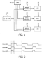
- FIG. 1 shows a conventional multi-channel lighting system driver circuit.
- Three LED loads 10,11,12 are shown, which may for example have three different color outputs.
- Each is driven by a respective driver 20,21,22 which essentially comprises a switch mode power supply (SMPS) or linear driver which implements PWM control.
- SMPS switch mode power supply
- the global controller 16 provides commands to the local drivers 20,21,22 to control the operation of the LED loads.
- the embodiments of the invention relates in particular to the control of the individual drivers 20,21,22.
- Each channel uses PWM signal control of the LED load, with the same PWM cycle frequency.
- each channel starts with a high pulse, the duration of which determines the light output.
- all three channels are activated at the same time giving a high power demand at the beginning of each PWM cycle.
- the maximum power is for example 15W.
- the control method above gives a total power of 45W.
- the output power swing is from 0 Watts to 45 Watts with four possible values of 45W, 30W, 15W, 0W.
- the power factor stage and DC-DC converter stage are typically combined together, and the cross frequency then needs to be below 20Hz in order to achieve a sufficiently high Power Factor.
- This means a large capacitor is needed to supply 50ms of additional power dissipation. In this case, the capacitor can be too large to be installed in the unit.
- the peak power will be derived from the highest peak current in the individual channels. In this case, the total peak power can be greatly reduced, giving space and cost savings for the drivers.
- This document discloses a phase shift method for implementing non-overlapping signals.
- the individual channels each comprise a delayed version of an input PWM signal with the same duty cycle.
- a delay locked loop calculates a pulse width of the input PWM signal by a high frequency clock signal (sampling frequency), and generates for each channel a respective phase-shifted PWM signal with the same pulse width but shifted in time by such width. More specifically, it has "the PW mirror duplicates and delays a received PWM signal".
- a turn-ON timing of each of the multiple phase-shifted PWM signals follows a turn-OFF timing of a previous PWM signal which is the input PWM signal or a previous one of the multiple phase-shifted PWM signals.
- the edge detector 201 detects a rising and/or a falling edge of the received PWM signal and a pulse width memory circuit 202 memorizes the pulse width of the received PWM signal.
- a method of controlling a lighting arrangement comprising a set of at least two light sources, the method comprising: switching on each light source for a respective lighting duration in a repeating non-overlapping sequence; and detecting the end of the lighting duration for one light source and using the detected end of the lighting duration for one light source as a timing trigger for switching on the next light source in the sequence; wherein the controller further comprises an adjustment interface, adapted to receive information about lengths of the durations, and wherein the controller is adapted to independently and individually configure each of the durations according to the received information.
- This method provides the activation of light sources in a non-overlapping sequence by detecting the end of one lighting time period and using this as a trigger for the next, so that the power requirement is kept to a minimum and overlapping is guaranteed.
- the embodiment of the invention enables the light source control signals to be provided in a simple manner. For example, in some implementations a global clock signal is not need to control the next light duration. Thus the cost is decreased since low end processor/circuit is capable of this operation.
- the embodiment of the invention also enables the lighting arrangement to be used at its maximum output given the constraint of non-overlapping control signals.
- the different light sources for example to achieve a given color output
- they can be made to fill the time available. For example with three light sources, they do not need to be constrained to occupy only up to one third of the period of the full sequence. This may help for shortening a dark duration wherein no light source is on thus decreasing the ripple/flicker.
- the components required for the driver design can be downgraded with benefit of cost savings, size reductions, power factor improvement, and efficiency improvement, which are critical to lighting product development.
- the next light source in the sequence is switched on, such that the lighting durations together cover each period of time during which the lighting arrangement is controlled.
- This approach provides the activation as a continuous non-overlapping sequence.
- the contribution of the different light sources can be controlled by varying the relative durations of the different light source signals.
- This example enables the light source control signals to be provided in a simple manner. For example, in some implementations the last light duration in one cycle can trigger the first light duration in the next cycle, thus a global clock signal is not need to control the repeating cycle. This may help for eliminating the dark duration wherein no light source is on thus decreasing the ripple/flicker.
- a control duration is triggered on by the end of the lighting duration for said at least one light source before the next light source in the sequence is switched on, and the end of the control duration is used as a timing trigger for switching on the next light source in the sequence, and the lighting durations for the light sources and the control duration or durations together cover each period of time during which the lighting arrangement is controlled; wherein the control duration is a blank channel which does not result in any light output.
- This approach provides the activation as a continuous non-overlapping sequence with a control duration period between one or more pairs of light source lighting durations.
- This control duration can be used to adjust the practical lighting output from the real lighting sources.
- the control duration can be used to define a period of no light output, in other words, not related to any of the real light sources.
- the control duration thus introduces a delay between the end of one light source output and the start of the next one in the cycle. For example, after the last light source in the sequence is activated, there can be a control delay before the first is re-activated. In this way, the system is operated below full light output and the total output lumen can be adjusted, and this thus provides a dimming control function dependent on the duration of the delay.
- the lighting durations for at least two light sources are in succession, and the control duration is triggered at the end of the successive lighting durations of the at least two light sources.
- the control duration is thus only after every two or more lighting durations, for example only after the full sequence. Since control channels are few, this solution is simple to realize.
- a respective control duration is triggered at the end of the lighting duration for each of the light sources. This approach provides the activation as a continuous non-overlapping sequence with a control duration between each pair of lighting durations. In this way, the system again is operated below full light output, and the control delays are spread over time and thus the dark duration between each light duration is short, helping to reduce flicker and ripple.
- the end of one lighting duration is used to trigger the next.
- the trigger may be immediate or delayed by a control duration.
- the term "used as a timing trigger" should be understood accordingly.
- time durations are preferably independently and individually selectable.
- the method can be for controlling a system comprising a set of three light sources giving different and adjustable color mixing and color temperature outputs, the method thereby providing color point control.
- the system can comprise a set of LED arrangements.
- the invention also provides a lighting controller for controlling a lighting arrangement comprising a set of at least two light sources, the controller comprising: a timing unit for controlling the timing of operation of the light sources in a repeating non-overlapping sequence, wherein the timing unit is adapted to switch on each light source for a respective lighting duration, wherein the timing unit further comprises a detection subunit adapted to detect the end of the lighting duration for one light source and the timing unit is adapted to use the detected end of the lighting duration as a timing trigger for switching on the next light source in the sequence.
- This controller implements the method of the invention.
- the timing unit comprises: a processor adapted to generate respective output signals for each of the durations, wherein the processor is further adapted to detect the trailing edge of one output signal corresponding to a first duration and, when the trailing edge is detected, to trigger another output signal corresponding to a second duration succeeding the first duration in the sequence.
- This detection of the processor output signals functions as a feedback approach for generating sequence of timing signals (lighting duration and control duration signals if used).
- Another advantage is that current low price commercial microprocessors/MCUs have this capability of detecting the trailing edge of its output, thus the cost to realize the embodiment is low.
- the trailing edge trigger solution is not used, but a microcontroller (MCU) is instead used to generate non-overlapping control signal by referring to the MCU's own clock, the MCU needs to be a high end device which has a higher cost.
- MCU microcontroller
- the timing unit comprises: a processor adapted to generate output signals for each of the lighting durations, wherein the output signals are on simultaneously but off at the end of the respective lighting durations; a set of one or more logic circuits, each circuit comprising: a first input for receiving a signal corresponding to a first duration from a corresponding output of the processor; a second input for receiving a signal corresponding to a second duration to be triggered by the end of the first duration from a corresponding output of the processor, wherein at least said second duration is a lighting duration; a logic operation module for calculating a logic result based on the signals corresponding to the first duration and the second duration, said logic result comprising the logic AND between the signal corresponding to the second duration and an inversion of the signal corresponding to the first duration; and an output for outputting said logic result as control signal to a corresponding one of the light sources.
- a processor adapted to generate output signals for each of the lighting durations, wherein the output signals are on simultaneously but off at the end of the respective lighting durations
- the different waveforms can be generated simply, all starting at the beginning of a periodic cycle, but ending at the desired end time of each lighting duration.
- Each logic circuit then coverts a pair of these overlapping signals into a desired non-overlapping signal.
- the logic circuit function thus makes use of the waveform transitions as trigger points, and thus implements the detection function.
- the advantage of this embodiment is it is relatively simple for a low end microprocessor / microcontroller to generate multiple signals with a simultaneous starting point and different ending point. Thus the cost to realize the embodiment is low.
- the controller can further comprise an adjustment interface, adapted to receive information about lengths of the durations (i. e. the lighting durations and the control durations if they are used), and the controller is adapted to independently and individually configure each of the durations according to the received information.
- an adjustment interface adapted to receive information about lengths of the durations (i. e. the lighting durations and the control durations if they are used), and the controller is adapted to independently and individually configure each of the durations according to the received information.
- the invention also provides a lighting system comprising: a lighting arrangement comprising a set of light sources; and a controller of the invention for controlling the lighting arrangement.
- said lighting arrangement comprises a set of drivers, each of which being adapted to drive one of said set of light sources respectively, and wherein said set of drivers is controlled by said controller to operate in the non-overlapping sequence.
- This embodiment provides one implementation about how the drivers are configured. There is a specific driver for each light source and the drivers are controlled in the non-overlapping sequence.
- said lighting arrangement comprises: a driver; a set of switches, wherein the input of each switch is coupled to said driver and the output of each switch is coupled to one of said set of light sources respectively, and said set of switches is controlled by said controller to be conductive in the non-overlapping sequence.
- This embodiment provides another implementation. There is only one single driver, and a set of switches, in the form of a switch box e.g., is provided to switch the single driver to each of the light source in the non-overlapping sequence.
- a set of switches in the form of a switch box e.g., is provided to switch the single driver to each of the light source in the non-overlapping sequence.
- the lighting arrangement comprises a set of three light sources giving different color outputs, wherein the light sources each comprise an LED arrangement.
- the invention provides a lighting controller and method in which light sources are activated for a respective time duration in a repeating non-overlapping sequence. The end of the time duration for one light source is detected to trigger the switching on of the next light source in the sequence. This provides non-overlapping control of the light sources and provides an efficient and easy to implement the required controller.
- each light source can comprise a single LED or a cluster of LEDs.
- the invention is not limited to LEDs, and the same concept can be applied to other light source devices.
- the invention is however of particular interest for LED lighting systems with two or more channels and where there is limited space for drivers such as for linear light sources.
- each channel triggers the next channel, and because a repeating sequence is defined, the last channel in one cycle triggers the first channel in the next cycle.
- the peak power is equal to the maximum peak power of the individual channels. The peak power can therefore be limited, resulting in a low power requirement for the AC-DC drivers to reduce space requirements.
- Figure 3 shows a first example of timing diagram implementing a method of the invention.
- the end of the lighting duration of channel 1 is detected and triggers the start of the lighting signal of channel 2.
- the end of the lighting duration of channel 2 is detected and triggers channel 3, then the end of the lighting duration of channel 3 is detected and triggers channel 1 to start a new cycle of the repeating sequence.
- start channel 1 To control the channels, only a start command to start channel 1 is needed. No other reference timing signal is needed.
- the duty cycles or the time duration of ON for each channel can be pre-set. Thus each channel, after being triggered, is switched on for that pre-set duration and then switched off. Thus operation is a simple operation that can be done by any microprocessor/microcontroller, including low end/cost versions.
- FIG. 3 shows a total duty for one cycle of 1 so that the activated lighting durations together cover each the time period during which the lighting arrangement is controlled.
- the lighting system will typically be controlled for successive periods of time. Each period of time is effectively when the lighting system is turned on and delivering a desired light output.
- the different channels are typically for different colors, and the different duty cycles for the different colors thus implement color point control and color temperature control. It will be apparent from the timing diagram of Figure 3 that every channel duty ratio can be selected independently.
- channel 1 has a 50% duty cycle for example for a red LED
- channel 2 has a 30% duty cycle for example for a green LED
- channel 3 has a 20% duty cycle for example for a blue LED.
- This arrangement operates at full output power. Furthermore, since at any time, one channel is on, the flicker/ripple is reduced.
- dimming control it is also possible to implement additional control, such as dimming control.
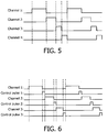
- an extra control channel can be added, as shown in Figure 4 as channel 4.
- this channel is a blank channel which does not result in any light output, for example used to control a dimming function. This blank channel is used for dimming out all light sources for a certain duration and also for triggering the light source ON again.
- the control duration is zero.
- detection of the end of channel 3 triggers the start of an ON duration/pulse in the control channel 4, and the detection of the end of the control channel ON duration then triggers channel 1 again and starts a new lighting cycle period.
- the control channel 4 has a desired control duration. It can therefore be processed in the same way as the durations which define the lighting durations, and thus can simply be processed as an extra lighting channel even though it is an effectively blank channel.
- the end of the control duration is detected as a further timing trigger, in the same way that the end of each of the lighting durations is detected and functions as a timing trigger.
- the next light source in the sequence (channel 1 in this case) is switched on after an intervening control duration.
- This control duration thus introduces a time delay during which no light source is activated. This time delay is the duration of the control duration on channel 4.
- the lighting durations and the control duration on channel 4 together cover all of the time during which the lighting arrangement is controlled.
- channel 4 can have a 10% duty cycle.
- this blank control channel can be further divided into multiple short blank control channels distributed among the lighting time periods of multiple LED channels. This prevents a long dark duration and ripple/flicker is reduced.
- This approach is shown in Figure 6 .
- the next light source in the sequence is switched on after a respective control duration.
- the lighting time durations and multiple control durations again cover all of the time period during which the lighting arrangement is controlled.
- Each individual control duration is the division of the desired overall off period (e.g. 10% from the example above) by the number of real light channels (e.g. 3 in the present embodiment).
- Examples have been given of a single control pulse duration in each cycle, or a number of control duration delays corresponding to the number of channels.
- the delay may be split into a different number, such as every 2nd or 3rd light source channel.
- a control duration is triggered on by the end of the lighting duration for that light source, before the next light source in the sequence is switched on.
- control channel is not related to any lighting source to provide dimming. But the control channel is not limited as such.
- the control channel can be related to other functionality to realize other technical effect.
- control channel can be selectively related to one of the lighting channels to provide compensation in color mixing.
- Figure 7 shows a first example of lighting system of the invention.
- the lighting arrangement comprises a set of drivers 20, 21 and 22, each of which being adapted to drive one of said set of light sources 10, 11 and 12 respectively, and wherein said set of drivers 20, 21 and 22is controlled by controller to operate in the non-overlapping sequence.
- the same components as in Figure 1 are given the same reference numbers.
- the difference resides in the global (remote) controller 70.
- the timing is achieved based on feedback of the channel signals.
- the controller simply applies a set duration to each channel after triggered to do so by the feedback signals, which are the outputs of the system.
- the controller 70 thus implements detection of the trailing end of each of the lighting durations as well as implementing timing of the lighting durations. This feedback is represented in simple form in Figure 7 by the arrows 72.
- the controller 70 thus comprises a timing unit, and a detection subunit (which can be considered as part of the timing unit).
- the repeating sequence waveforms are used as feedback control inputs to provide timing triggers which the timing unit uses as inputs.
- the controller thus generates respective output signals for each of the durations, and by using the feedback shown, the controller is adapted to detect the trailing edge of one output signal corresponding to a first duration and, when the trailing edge is detected, to trigger another output signal corresponding to a second duration succeeding the first duration in the sequence.
- three output signals are shown for the three light sources.
- a fourth control channel is also used as a feedback input as explained above and as shown by arrow 72'. Physically, the port of this channel can be entirely internal within the controller 70, or is an output port but isolated from other components, since it is a blank channel not needed as a real output to the driver. In case of using the control channel for other functionality, the port of this control channel can be connected to other components.
- the controller 70 further comprises an adjustment interface 74, which receives information 76 about the desired lengths of the lighting durations (e.g. for color point control) and the control duration or durations (e.g. for dimming control), and the controller 70 can independently and individually configure each of the durations according to the received information.
- an adjustment interface 74 which receives information 76 about the desired lengths of the lighting durations (e.g. for color point control) and the control duration or durations (e.g. for dimming control), and the controller 70 can independently and individually configure each of the durations according to the received information.
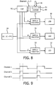
- Figure 8 shows a second example of lighting system of the invention.
- the same components as in Figures 1 and 7 are again given the same reference numbers.
- the difference resides in the global (remote) controller 80 and also the addition of a logic gate arrangement 82.
- Figure 9 shows a timing diagram giving the desired timing signals in conventional overlapping format. This example is based on channel 1 with a 50% duty cycle (red LED), channel 2 with a 15% duty cycle (green LED) and channel 3 with a 15% duty cycle (blue LED). This leaves a 20% duty cycle blank. This set of signals thus gives an 80% output power at a specific color point.
- the controller 80 provides cumulative signals as shown by the top three plots in Figure 10 .
- the controller generates output signals for each of the lighting durations, wherein the output signals are ON simultaneously at the start of the cycle but off at the end of the respective lighting durations.
- the duration of the lighting pulse for channel 1 is unchanged.
- the duration of the lighting pulse for channel 2 is equal to the durations for channel 1 + channel 2
- the duration of the lighting pulse for channel 3 is equal to channel 1 + channel 2 + channel 3. This gives channel 1 a 50% duty cycle, channel 2 a 65% duty cycle and channel 3 an 80% duty cycle.
- control duration is simply defined as the remaining time duration in the period after all the lighting pulses have been elapsed. It should be understood that a control duration or multiple control durations can however also be used for this embodiment.
- Figure 11 shows an example of logic circuit arrangement which can generate the lower three plots in Figure 10 from the upper three plots.
- the logic circuit arrangement comprises two AND gates and two NOT gates.
- the logic circuit arrangement thus passes the first lighting channel, but for each other lighting channel there is a logic circuit 110, comprising: a first input for receiving a signal corresponding to a first duration which relates to the preceding light source in the sequence; a second input for receiving a signal corresponding to a second duration to be triggered by the end of the first duration which relates to the light source signal being generated; a logic operation module (the NOT gate and AND gate) for calculating a logic result based on the signals corresponding to the first duration and the second duration, which is the logic AND between the signal corresponding to the second duration and an inversion of the signal corresponding to the first duration.
- Such logic circuits 110 generate the channels B and C.
- Signal A is for LED 10
- signal B is for LED 11
- signal C is for LED 12.
- the logic circuit arrangement thus implements the detection of trailing edges and uses these as timing triggers for the generation of the lighting pulses. This imposes very little additional overhead to the controller.
- the use of a circuit means that the initial channel information is in the form of timing waveforms for each light source which start at the same time, so they can be generated in a simple manner, without requiring specific clock timing. No separate control channel is needed when the blank control period is after all the lighting durations, as in Figure 10 .
- control channels can also be used for input into the logic arrangement in order to provide distributed control periods as in Figure 6 .
- the invention has been tested, and has been found to reduce the total power of an example of AC-DC driver from 45W to 25W.
- the total space of the AC-DC driver can then be reduced by about 30% together with a total 15% cost reduction for the drivers.
- the total applicable power for the individual LEDs was at the same time increased from 15W to 30W.
- the lighting system comprises one single driver 20 such a constant current source/driver, and a set of switches.
- the input of each switch is coupled to the driver 20 and the output of each switch is coupled to one of two light sources 10 and 11 respectively.
- the set of switches S1 and S2 is controlled by a controller 90 similar as discussed above, and the switches are controlled to be conductive in the non-overlapping sequence. It should be clear that in practice also more than two LEDs can and will be used to make an LED string. Also it is possible that multiple strings in parallel or various series-parallel configurations of LED can be used behind the switches S1 and S2. For simplicity we will however discuss only the simple case of a LED string that consists of a single series-connection of LEDs.
- controller 90 The specific implementation of the controller 90 is similar as above, thus the description will not give unnecessary description.
- an adjustment interface 74 which is adapted to receive the hue/color temperature adjusting command.
- Such control interface may be a DALI interface or a Zigbee wireless interface.
- the controller 90 obtains the desired hue/color temperature and calculates the proper duty cycles of these light sources 10 and 11.
- the exact duty cycles to be applied can either be configured by means of jumpers, configurable resistors, near field communication, DIP switches or other means to set a static setting.
- the controller 90 controls the corresponding switches S1 and S2 to be conductive complementary/non-overlapping for its corresponding duration.
- Fig. 13 shows three sets of controlling signal to the switches S1 and S2. In the first set, S1 is ON for a longer duration than that of S2.
- S1 and S2 are ON for a substantially same duration.
- S1 is ON for a shorter duration than that of S2.
- these three set of control signal essentially obtain the same lumen output but different overall color temperatures.
- this embodiment may control the driver 20 via DALI protocol (IEC 62386) or 1-10V protocol (IEC 60929-E), and lowers the current it provides.
- DALI protocol IEC 62386
- 1-10V protocol IEC 60929-E
- a capacitor C may be present in the circuit at the output of the driver before the set of switches, which capacitor can buffer any current imbalances during these periods.
- resistors R1 and R2 may be added in series with the switch and the light source to reduce this effect.
- the set of switches with the controller and the adjustment interface can be integrated as a separate module different from the driver, such as being implemented as an add-on box, which does not change the current driver and saves a lot.
- the invention can be applied into all types of multi-channel light system which requires at least two channels to drive the light sources, such as for color mixing or for correlated color temperature (CCT) light sources.
- CCT correlated color temperature
- the system makes use of a lighting controller.
- Components that may be employed for the controller include, but are not limited to, conventional microprocessors, application specific integrated circuits (ASICs), microcontrollers (MCUs), and field-programmable gate arrays (FPGAs).
- ASICs application specific integrated circuits
- MCUs microcontrollers
- FPGAs field-programmable gate arrays
- a processor or controller may be associated with one or more storage media such as volatile and non-volatile computer memory such as RAM, PROM, EPROM, and EEPROM.
- the storage media may be encoded with one or more programs that, when executed on one or more processors and/or controllers, perform at the required functions.
- Various storage media may be fixed within a processor or controller or may be transportable, such that the one or more programs stored thereon can be loaded into a processor or controller.
Landscapes
- Physics & Mathematics (AREA)
- Engineering & Computer Science (AREA)
- Microelectronics & Electronic Packaging (AREA)
- Optics & Photonics (AREA)
- Circuit Arrangement For Electric Light Sources In General (AREA)
Priority Applications (1)
| Application Number | Priority Date | Filing Date | Title |
|---|---|---|---|
| EP14801955.7A EP2949182B2 (en) | 2013-11-25 | 2014-11-06 | A method of controlling a lighting arrangement, a lighting controller and a lighting system |
Applications Claiming Priority (4)
| Application Number | Priority Date | Filing Date | Title |
|---|---|---|---|
| CN2013001437 | 2013-11-25 | ||
| EP14152510 | 2014-01-24 | ||
| PCT/EP2014/073853 WO2015074881A1 (en) | 2013-11-25 | 2014-11-06 | A method of controlling a lighting arrangement, a lighting controller and a lighting system |
| EP14801955.7A EP2949182B2 (en) | 2013-11-25 | 2014-11-06 | A method of controlling a lighting arrangement, a lighting controller and a lighting system |
Publications (3)
| Publication Number | Publication Date |
|---|---|
| EP2949182A1 EP2949182A1 (en) | 2015-12-02 |
| EP2949182B1 EP2949182B1 (en) | 2017-06-21 |
| EP2949182B2 true EP2949182B2 (en) | 2020-04-22 |
Family
ID=51945838
Family Applications (1)
| Application Number | Title | Priority Date | Filing Date |
|---|---|---|---|
| EP14801955.7A Active EP2949182B2 (en) | 2013-11-25 | 2014-11-06 | A method of controlling a lighting arrangement, a lighting controller and a lighting system |
Country Status (5)
| Country | Link |
|---|---|
| US (1) | US9609703B2 (ja) |
| EP (1) | EP2949182B2 (ja) |
| JP (1) | JP6096332B2 (ja) |
| RU (1) | RU2673249C2 (ja) |
| WO (1) | WO2015074881A1 (ja) |
Families Citing this family (23)
| Publication number | Priority date | Publication date | Assignee | Title |
|---|---|---|---|---|
| US10267506B2 (en) * | 2010-11-22 | 2019-04-23 | Cree, Inc. | Solid state lighting apparatuses with non-uniformly spaced emitters for improved heat distribution, system having the same, and methods having the same |
| JP6410076B2 (ja) * | 2014-03-28 | 2018-10-24 | シーシーエス株式会社 | 電源装置及びled照明装置 |
| US10806002B2 (en) * | 2014-05-12 | 2020-10-13 | SMR Patents S.à.r.l. | Rear view device assemblies and circuits |
| WO2016169961A1 (en) | 2015-04-24 | 2016-10-27 | Philips Lighting Holding B.V. | A solid state lighting module, a lighting circuit and lighting control methods. |
| US10506692B2 (en) * | 2015-09-11 | 2019-12-10 | Signify Holding B.V. | Automatic grid mapping through timing |
| CN105592587B (zh) * | 2015-12-12 | 2017-07-07 | 浙江凯耀照明股份有限公司 | Led灯的控制方法 |
| FI128220B (fi) | 2016-02-24 | 2019-12-31 | Teknoware Oy | LED-valolähde ja menetelmä LED-valolähteen värisävyn tai värilämpötilan säätämiseen |
| CN106131996B (zh) * | 2016-06-24 | 2017-12-26 | 成都芯源系统有限公司 | 一种发光二极管驱动系统及其驱动方法 |
| ES2783893T3 (es) * | 2017-03-15 | 2020-09-18 | Signify Holding Bv | Disposición y método de control de diodos emisores de luz |
| CN108633124B (zh) * | 2017-03-20 | 2021-06-08 | 朗德万斯公司 | 可调光led灯及其操作方法、用于可调光led灯的灯驱动器 |
| EP3613261A4 (en) * | 2017-04-21 | 2020-09-30 | Verdant Lighting Technology, Inc. | LIGHTING SYSTEM WITH LUMINESCENT DIODES |
| CN110832426B (zh) * | 2017-07-04 | 2021-03-19 | 罗姆股份有限公司 | 负载驱动装置 |
| CN109548223A (zh) * | 2017-09-22 | 2019-03-29 | 欧司朗有限公司 | 用于驱动多个发光负载链的驱动装置和照明装置 |
| US10728976B2 (en) * | 2018-05-15 | 2020-07-28 | Robern, Inc. | LED control method for perceived mixing |
| JP7065352B2 (ja) * | 2018-05-24 | 2022-05-12 | パナソニックIpマネジメント株式会社 | Led点灯装置および照明器具 |
| DE102019218941A1 (de) * | 2018-12-10 | 2020-06-10 | Koito Manufacturing Co., Ltd. | Lampenmodul |
| JP7365866B2 (ja) * | 2018-12-10 | 2023-10-20 | 株式会社小糸製作所 | 灯具モジュール |
| WO2020141558A1 (en) * | 2019-01-04 | 2020-07-09 | Hero MotoCorp Limited | Lighting circuitry of vehicle |
| NL2022561B1 (en) | 2019-02-12 | 2020-08-27 | Schreder Sa | Light system with controllable branches of light elements |
| US10841998B1 (en) | 2019-05-17 | 2020-11-17 | Signify Holding B.V. | Shared power topology for LED luminaires |
| CN114175858A (zh) | 2019-07-19 | 2022-03-11 | 昕诺飞控股有限公司 | 对2通道cct调光的改进平衡控制 |
| KR20220048718A (ko) * | 2020-10-13 | 2022-04-20 | 현대자동차주식회사 | 단일 채널 기반 다기능 led 램프 구동 시스템 및 방법 |
| CN113434199B (zh) * | 2021-08-27 | 2021-11-23 | 南京沁恒微电子股份有限公司 | 一种可驱动多组rgb灯的mcu及其驱动方法 |
Citations (1)
| Publication number | Priority date | Publication date | Assignee | Title |
|---|---|---|---|---|
| US20070216320A1 (en) † | 2006-03-16 | 2007-09-20 | Grivas Chris J | Method and apparatus for illuminating light sources within an electronic device |
Family Cites Families (31)
| Publication number | Priority date | Publication date | Assignee | Title |
|---|---|---|---|---|
| US4257029A (en) * | 1974-12-26 | 1981-03-17 | Stevens Carlile R | Traffic control system |
| US4370718A (en) * | 1979-02-06 | 1983-01-25 | Chasek Norman E | Responsive traffic light control system and method based on conservation of aggregate momentum |
| US5943086A (en) * | 1996-03-11 | 1999-08-24 | Ricoh Company, Ltd. | Multiple beam independent activation system and method for simultaneous image formation |
| JPH09311312A (ja) * | 1996-05-24 | 1997-12-02 | Matsushita Electric Ind Co Ltd | 液晶プロジェクター |
| JPH11119733A (ja) | 1997-10-16 | 1999-04-30 | Toyoda Gosei Co Ltd | 発光ダイオードの電源装置 |
| US6191818B1 (en) * | 1998-08-14 | 2001-02-20 | Intel Corporation | Method and apparatus for generating a projectable subject viewfinder |
| JP2000214825A (ja) * | 1999-01-20 | 2000-08-04 | Nec Corp | バックライト表示装置及び方法 |
| US7604378B2 (en) * | 2003-07-02 | 2009-10-20 | S.C. Johnson & Son, Inc. | Color changing outdoor lights with active ingredient and sound emission |
| US7348949B2 (en) | 2004-03-11 | 2008-03-25 | Avago Technologies Ecbu Ip Pte Ltd | Method and apparatus for controlling an LED based light system |
| US7141941B2 (en) | 2004-04-28 | 2006-11-28 | Intersil Americas Inc. | Staggering switching signals for multiple cold cathode fluorescent lamp backlighting system to reduce electromagnetic interference |
| CN100552765C (zh) | 2006-04-25 | 2009-10-21 | 友达光电股份有限公司 | 液晶显示器及彩色图像的显示方法及控制光源的方法 |
| JP5124130B2 (ja) * | 2006-06-23 | 2013-01-23 | エルジー ディスプレイ カンパニー リミテッド | 液晶表示装置のバックライトを駆動する装置及び方法 |
| WO2008075266A2 (en) * | 2006-12-19 | 2008-06-26 | Philips Intellectual Property & Standards Gmbh | Colour sequential flash for digital image acquisition |
| JP4951369B2 (ja) * | 2007-02-23 | 2012-06-13 | パナソニック株式会社 | 照明装置及び照明システム |
| DE102007013742A1 (de) | 2007-03-22 | 2008-10-02 | Osram Gesellschaft mit beschränkter Haftung | Betriebsgerät und Verfahren für den kombinierten Betrieb von Gasentladungslampen und Halbleiterlichtquellen |
| US7665874B2 (en) * | 2007-03-30 | 2010-02-23 | Chadwell Thomas J | Method and apparatus for delivering visual information |
| US8531126B2 (en) * | 2008-02-13 | 2013-09-10 | Canon Components, Inc. | White light emitting apparatus and line illuminator using the same in image reading apparatus |
| US20090225020A1 (en) * | 2008-03-07 | 2009-09-10 | O2Micro, Inc. | Backlight controller for driving light sources |
| US20090273282A1 (en) * | 2008-03-07 | 2009-11-05 | Ballard Claudio R | Configurable tail light module |
| US7843148B2 (en) | 2008-04-08 | 2010-11-30 | Micrel, Inc. | Driving multiple parallel LEDs with reduced power supply ripple |
| JP2010021008A (ja) | 2008-07-10 | 2010-01-28 | Koizumi Lighting Technology Corp | Led照明装置 |
| JP2010139543A (ja) | 2008-12-09 | 2010-06-24 | Sony Corp | 表示装置、電子機器および表示装置の駆動方法 |
| TWI420965B (zh) * | 2009-05-26 | 2013-12-21 | Richtek Technology Corp | 具有移相調光功能之led控制器及led移相調光電路與相關方法 |
| US8569956B2 (en) * | 2009-06-04 | 2013-10-29 | Point Somee Limited Liability Company | Apparatus, method and system for providing AC line power to lighting devices |
| TWI403215B (zh) | 2009-10-01 | 2013-07-21 | Upec Electronics Corp | Color Modulation System and Its Modulation Method |
| CN102469665B (zh) | 2010-11-17 | 2014-07-16 | 晨星软件研发(深圳)有限公司 | 发光二极管驱动系统及驱动方法 |
| US9089017B2 (en) | 2010-12-02 | 2015-07-21 | Defond Components Limited | Method of controlling lights and controller therefor |
| US8513901B2 (en) * | 2010-12-10 | 2013-08-20 | Texas Instruments Incorporated | Method and apparatus to control LED brightness |
| CN103283305A (zh) | 2010-12-21 | 2013-09-04 | 皇家飞利浦电子股份有限公司 | 用于多通道照明的装置、系统和方法 |
| US8710752B2 (en) | 2011-03-03 | 2014-04-29 | Dialog Semiconductor Inc. | Adaptive switch mode LED system |
| JP2013069448A (ja) | 2011-09-21 | 2013-04-18 | Panasonic Corp | 点灯装置およびそれを備えた照明器具 |
-
2014
- 2014-11-06 US US14/908,139 patent/US9609703B2/en active Active
- 2014-11-06 JP JP2015563165A patent/JP6096332B2/ja active Active
- 2014-11-06 WO PCT/EP2014/073853 patent/WO2015074881A1/en active Application Filing
- 2014-11-06 EP EP14801955.7A patent/EP2949182B2/en active Active
- 2014-11-06 RU RU2015147862A patent/RU2673249C2/ru active
Patent Citations (1)
| Publication number | Priority date | Publication date | Assignee | Title |
|---|---|---|---|---|
| US20070216320A1 (en) † | 2006-03-16 | 2007-09-20 | Grivas Chris J | Method and apparatus for illuminating light sources within an electronic device |
Also Published As
| Publication number | Publication date |
|---|---|
| RU2015147862A3 (ja) | 2018-09-24 |
| EP2949182A1 (en) | 2015-12-02 |
| EP2949182B1 (en) | 2017-06-21 |
| JP6096332B2 (ja) | 2017-03-15 |
| US20160255687A1 (en) | 2016-09-01 |
| RU2015147862A (ru) | 2017-05-11 |
| US9609703B2 (en) | 2017-03-28 |
| JP2016527655A (ja) | 2016-09-08 |
| RU2673249C2 (ru) | 2018-11-23 |
| WO2015074881A1 (en) | 2015-05-28 |
Similar Documents
| Publication | Publication Date | Title |
|---|---|---|
| EP2949182B2 (en) | A method of controlling a lighting arrangement, a lighting controller and a lighting system | |
| US9723244B2 (en) | Low cost LED driver with improved serial bus | |
| EP2916620B1 (en) | Hybrid dimming control techniques for LED drivers | |
| KR101189253B1 (ko) | 고정위상 모드를 갖는 디지털 pwm방식에서 디밍 신호를 이용한 dc-dc 컨버터용 pwm 신호 생성회로 및 이를 이용한 led 구동회로 | |
| US8508204B2 (en) | Controller and method of operating a controller | |
| US7321199B2 (en) | Display apparatus and control method thereof | |
| US20200296813A1 (en) | Modular lighting application | |
| US8134305B2 (en) | Light source driving apparatus | |
| US9596723B2 (en) | PWM signal generating circuit for DC-DC converter using dimming signal and LED driving circuit having the same in direct digital dimming method | |
| US20180034450A1 (en) | Ramp based clock synchronization for stackable circuits | |
| WO2009125377A1 (en) | Rotating pulse-with modulator | |
| CN105191496B (zh) | 控制照明装置的方法,照明控制器和照明系统 | |
| Hasan et al. | A RGB-driver for LED display panels | |
| KR101224958B1 (ko) | 전류 비교기를 이용한 발광 다이오드 구동 방법 및 이를 기반으로 운용되는 발광 다이오드 구동 회로 | |
| EP2814300B1 (en) | A driver for a light source | |
| US10485063B2 (en) | Power supply circuit, and related lighting system and method for operating a power supply circuit | |
| EP3711456B1 (en) | Solid state lighting circuit and control method | |
| TWI533748B (zh) | Light - emitting diode circuit system with power factor correction and optimization | |
| CN111770604B (zh) | 发光装置及其控制方法 | |
| KR20130065483A (ko) | Led 회로 |
Legal Events
| Date | Code | Title | Description |
|---|---|---|---|
| PUAI | Public reference made under article 153(3) epc to a published international application that has entered the european phase |
Free format text: ORIGINAL CODE: 0009012 |
|
| 17P | Request for examination filed |
Effective date: 20150828 |
|
| AK | Designated contracting states |
Kind code of ref document: A1 Designated state(s): AL AT BE BG CH CY CZ DE DK EE ES FI FR GB GR HR HU IE IS IT LI LT LU LV MC MK MT NL NO PL PT RO RS SE SI SK SM TR |
|
| AX | Request for extension of the european patent |
Extension state: BA ME |
|
| RAP1 | Party data changed (applicant data changed or rights of an application transferred) |
Owner name: PHILIPS LIGHTING HOLDING B.V. |
|
| GRAP | Despatch of communication of intention to grant a patent |
Free format text: ORIGINAL CODE: EPIDOSNIGR1 |
|
| DAX | Request for extension of the european patent (deleted) | ||
| INTG | Intention to grant announced |
Effective date: 20170116 |
|
| GRAS | Grant fee paid |
Free format text: ORIGINAL CODE: EPIDOSNIGR3 |
|
| GRAA | (expected) grant |
Free format text: ORIGINAL CODE: 0009210 |
|
| AK | Designated contracting states |
Kind code of ref document: B1 Designated state(s): AL AT BE BG CH CY CZ DE DK EE ES FI FR GB GR HR HU IE IS IT LI LT LU LV MC MK MT NL NO PL PT RO RS SE SI SK SM TR |
|
| REG | Reference to a national code |
Ref country code: GB Ref legal event code: FG4D |
|
| REG | Reference to a national code |
Ref country code: CH Ref legal event code: EP |
|
| REG | Reference to a national code |
Ref country code: IE Ref legal event code: FG4D |
|
| REG | Reference to a national code |
Ref country code: AT Ref legal event code: REF Ref document number: 903970 Country of ref document: AT Kind code of ref document: T Effective date: 20170715 |
|
| REG | Reference to a national code |
Ref country code: DE Ref legal event code: R096 Ref document number: 602014011088 Country of ref document: DE |
|
| RIN2 | Information on inventor provided after grant (corrected) |
Inventor name: WANG, SHAN Inventor name: DUINE, PETER ALEXANDER Inventor name: LIU, JUNHU Inventor name: FU, JIE Inventor name: ZHANG, XIANHUI Inventor name: HAVERLAG, MARCO Inventor name: XU, SHU Inventor name: GIELEN, HERMAN JOHANNES GERTRUDIS |
|
| REG | Reference to a national code |
Ref country code: NL Ref legal event code: MP Effective date: 20170621 |
|
| PG25 | Lapsed in a contracting state [announced via postgrant information from national office to epo] |
Ref country code: HR Free format text: LAPSE BECAUSE OF FAILURE TO SUBMIT A TRANSLATION OF THE DESCRIPTION OR TO PAY THE FEE WITHIN THE PRESCRIBED TIME-LIMIT Effective date: 20170621 Ref country code: FI Free format text: LAPSE BECAUSE OF FAILURE TO SUBMIT A TRANSLATION OF THE DESCRIPTION OR TO PAY THE FEE WITHIN THE PRESCRIBED TIME-LIMIT Effective date: 20170621 Ref country code: GR Free format text: LAPSE BECAUSE OF FAILURE TO SUBMIT A TRANSLATION OF THE DESCRIPTION OR TO PAY THE FEE WITHIN THE PRESCRIBED TIME-LIMIT Effective date: 20170922 Ref country code: NO Free format text: LAPSE BECAUSE OF FAILURE TO SUBMIT A TRANSLATION OF THE DESCRIPTION OR TO PAY THE FEE WITHIN THE PRESCRIBED TIME-LIMIT Effective date: 20170921 Ref country code: LT Free format text: LAPSE BECAUSE OF FAILURE TO SUBMIT A TRANSLATION OF THE DESCRIPTION OR TO PAY THE FEE WITHIN THE PRESCRIBED TIME-LIMIT Effective date: 20170621 |
|
| REG | Reference to a national code |
Ref country code: LT Ref legal event code: MG4D |
|
| REG | Reference to a national code |
Ref country code: AT Ref legal event code: MK05 Ref document number: 903970 Country of ref document: AT Kind code of ref document: T Effective date: 20170621 |
|
| REG | Reference to a national code |
Ref country code: FR Ref legal event code: PLFP Year of fee payment: 4 |
|
| PG25 | Lapsed in a contracting state [announced via postgrant information from national office to epo] |
Ref country code: LV Free format text: LAPSE BECAUSE OF FAILURE TO SUBMIT A TRANSLATION OF THE DESCRIPTION OR TO PAY THE FEE WITHIN THE PRESCRIBED TIME-LIMIT Effective date: 20170621 Ref country code: BG Free format text: LAPSE BECAUSE OF FAILURE TO SUBMIT A TRANSLATION OF THE DESCRIPTION OR TO PAY THE FEE WITHIN THE PRESCRIBED TIME-LIMIT Effective date: 20170921 Ref country code: SE Free format text: LAPSE BECAUSE OF FAILURE TO SUBMIT A TRANSLATION OF THE DESCRIPTION OR TO PAY THE FEE WITHIN THE PRESCRIBED TIME-LIMIT Effective date: 20170621 Ref country code: RS Free format text: LAPSE BECAUSE OF FAILURE TO SUBMIT A TRANSLATION OF THE DESCRIPTION OR TO PAY THE FEE WITHIN THE PRESCRIBED TIME-LIMIT Effective date: 20170621 Ref country code: NL Free format text: LAPSE BECAUSE OF FAILURE TO SUBMIT A TRANSLATION OF THE DESCRIPTION OR TO PAY THE FEE WITHIN THE PRESCRIBED TIME-LIMIT Effective date: 20170621 |
|
| PG25 | Lapsed in a contracting state [announced via postgrant information from national office to epo] |
Ref country code: RO Free format text: LAPSE BECAUSE OF FAILURE TO SUBMIT A TRANSLATION OF THE DESCRIPTION OR TO PAY THE FEE WITHIN THE PRESCRIBED TIME-LIMIT Effective date: 20170621 Ref country code: EE Free format text: LAPSE BECAUSE OF FAILURE TO SUBMIT A TRANSLATION OF THE DESCRIPTION OR TO PAY THE FEE WITHIN THE PRESCRIBED TIME-LIMIT Effective date: 20170621 Ref country code: CZ Free format text: LAPSE BECAUSE OF FAILURE TO SUBMIT A TRANSLATION OF THE DESCRIPTION OR TO PAY THE FEE WITHIN THE PRESCRIBED TIME-LIMIT Effective date: 20170621 Ref country code: SK Free format text: LAPSE BECAUSE OF FAILURE TO SUBMIT A TRANSLATION OF THE DESCRIPTION OR TO PAY THE FEE WITHIN THE PRESCRIBED TIME-LIMIT Effective date: 20170621 Ref country code: AT Free format text: LAPSE BECAUSE OF FAILURE TO SUBMIT A TRANSLATION OF THE DESCRIPTION OR TO PAY THE FEE WITHIN THE PRESCRIBED TIME-LIMIT Effective date: 20170621 |
|
| PG25 | Lapsed in a contracting state [announced via postgrant information from national office to epo] |
Ref country code: IT Free format text: LAPSE BECAUSE OF FAILURE TO SUBMIT A TRANSLATION OF THE DESCRIPTION OR TO PAY THE FEE WITHIN THE PRESCRIBED TIME-LIMIT Effective date: 20170621 Ref country code: SM Free format text: LAPSE BECAUSE OF FAILURE TO SUBMIT A TRANSLATION OF THE DESCRIPTION OR TO PAY THE FEE WITHIN THE PRESCRIBED TIME-LIMIT Effective date: 20170621 Ref country code: IS Free format text: LAPSE BECAUSE OF FAILURE TO SUBMIT A TRANSLATION OF THE DESCRIPTION OR TO PAY THE FEE WITHIN THE PRESCRIBED TIME-LIMIT Effective date: 20171021 Ref country code: PL Free format text: LAPSE BECAUSE OF FAILURE TO SUBMIT A TRANSLATION OF THE DESCRIPTION OR TO PAY THE FEE WITHIN THE PRESCRIBED TIME-LIMIT Effective date: 20170621 Ref country code: ES Free format text: LAPSE BECAUSE OF FAILURE TO SUBMIT A TRANSLATION OF THE DESCRIPTION OR TO PAY THE FEE WITHIN THE PRESCRIBED TIME-LIMIT Effective date: 20170621 |
|
| REG | Reference to a national code |
Ref country code: DE Ref legal event code: R026 Ref document number: 602014011088 Country of ref document: DE |
|
| PLBI | Opposition filed |
Free format text: ORIGINAL CODE: 0009260 |
|
| PLAX | Notice of opposition and request to file observation + time limit sent |
Free format text: ORIGINAL CODE: EPIDOSNOBS2 |
|
| 26 | Opposition filed |
Opponent name: MOLNIA, DAVID Effective date: 20180321 |
|
| PG25 | Lapsed in a contracting state [announced via postgrant information from national office to epo] |
Ref country code: DK Free format text: LAPSE BECAUSE OF FAILURE TO SUBMIT A TRANSLATION OF THE DESCRIPTION OR TO PAY THE FEE WITHIN THE PRESCRIBED TIME-LIMIT Effective date: 20170621 |
|
| PG25 | Lapsed in a contracting state [announced via postgrant information from national office to epo] |
Ref country code: MC Free format text: LAPSE BECAUSE OF FAILURE TO SUBMIT A TRANSLATION OF THE DESCRIPTION OR TO PAY THE FEE WITHIN THE PRESCRIBED TIME-LIMIT Effective date: 20170621 |
|
| PLBB | Reply of patent proprietor to notice(s) of opposition received |
Free format text: ORIGINAL CODE: EPIDOSNOBS3 |
|
| PG25 | Lapsed in a contracting state [announced via postgrant information from national office to epo] |
Ref country code: CH Free format text: LAPSE BECAUSE OF NON-PAYMENT OF DUE FEES Effective date: 20171130 Ref country code: LI Free format text: LAPSE BECAUSE OF NON-PAYMENT OF DUE FEES Effective date: 20171130 |
|
| PG25 | Lapsed in a contracting state [announced via postgrant information from national office to epo] |
Ref country code: SI Free format text: LAPSE BECAUSE OF FAILURE TO SUBMIT A TRANSLATION OF THE DESCRIPTION OR TO PAY THE FEE WITHIN THE PRESCRIBED TIME-LIMIT Effective date: 20170621 Ref country code: LU Free format text: LAPSE BECAUSE OF NON-PAYMENT OF DUE FEES Effective date: 20171106 |
|
| REG | Reference to a national code |
Ref country code: BE Ref legal event code: MM Effective date: 20171130 |
|
| REG | Reference to a national code |
Ref country code: IE Ref legal event code: MM4A |
|
| PG25 | Lapsed in a contracting state [announced via postgrant information from national office to epo] |
Ref country code: MT Free format text: LAPSE BECAUSE OF NON-PAYMENT OF DUE FEES Effective date: 20171106 |
|
| PG25 | Lapsed in a contracting state [announced via postgrant information from national office to epo] |
Ref country code: IE Free format text: LAPSE BECAUSE OF NON-PAYMENT OF DUE FEES Effective date: 20171106 |
|
| PG25 | Lapsed in a contracting state [announced via postgrant information from national office to epo] |
Ref country code: BE Free format text: LAPSE BECAUSE OF NON-PAYMENT OF DUE FEES Effective date: 20171130 |
|
| RAP2 | Party data changed (patent owner data changed or rights of a patent transferred) |
Owner name: PHILIPS LIGHTING HOLDING B.V. |
|
| RAP2 | Party data changed (patent owner data changed or rights of a patent transferred) |
Owner name: SIGNIFY HOLDING B.V. |
|
| PG25 | Lapsed in a contracting state [announced via postgrant information from national office to epo] |
Ref country code: HU Free format text: LAPSE BECAUSE OF FAILURE TO SUBMIT A TRANSLATION OF THE DESCRIPTION OR TO PAY THE FEE WITHIN THE PRESCRIBED TIME-LIMIT; INVALID AB INITIO Effective date: 20141106 |
|
| PG25 | Lapsed in a contracting state [announced via postgrant information from national office to epo] |
Ref country code: CY Free format text: LAPSE BECAUSE OF FAILURE TO SUBMIT A TRANSLATION OF THE DESCRIPTION OR TO PAY THE FEE WITHIN THE PRESCRIBED TIME-LIMIT Effective date: 20170621 |
|
| REG | Reference to a national code |
Ref country code: DE Ref legal event code: R079 Ref document number: 602014011088 Country of ref document: DE Free format text: PREVIOUS MAIN CLASS: H05B0033080000 Ipc: H05B0045000000 |
|
| PG25 | Lapsed in a contracting state [announced via postgrant information from national office to epo] |
Ref country code: MK Free format text: LAPSE BECAUSE OF FAILURE TO SUBMIT A TRANSLATION OF THE DESCRIPTION OR TO PAY THE FEE WITHIN THE PRESCRIBED TIME-LIMIT Effective date: 20170621 |
|
| PUAH | Patent maintained in amended form |
Free format text: ORIGINAL CODE: 0009272 |
|
| STAA | Information on the status of an ep patent application or granted ep patent |
Free format text: STATUS: PATENT MAINTAINED AS AMENDED |
|
| PG25 | Lapsed in a contracting state [announced via postgrant information from national office to epo] |
Ref country code: TR Free format text: LAPSE BECAUSE OF FAILURE TO SUBMIT A TRANSLATION OF THE DESCRIPTION OR TO PAY THE FEE WITHIN THE PRESCRIBED TIME-LIMIT Effective date: 20170621 |
|
| 27A | Patent maintained in amended form |
Effective date: 20200422 |
|
| AK | Designated contracting states |
Kind code of ref document: B2 Designated state(s): AL AT BE BG CH CY CZ DE DK EE ES FI FR GB GR HR HU IE IS IT LI LT LU LV MC MK MT NL NO PL PT RO RS SE SI SK SM TR |
|
| REG | Reference to a national code |
Ref country code: DE Ref legal event code: R102 Ref document number: 602014011088 Country of ref document: DE |
|
| PG25 | Lapsed in a contracting state [announced via postgrant information from national office to epo] |
Ref country code: PT Free format text: LAPSE BECAUSE OF FAILURE TO SUBMIT A TRANSLATION OF THE DESCRIPTION OR TO PAY THE FEE WITHIN THE PRESCRIBED TIME-LIMIT Effective date: 20170621 |
|
| PG25 | Lapsed in a contracting state [announced via postgrant information from national office to epo] |
Ref country code: AL Free format text: LAPSE BECAUSE OF FAILURE TO SUBMIT A TRANSLATION OF THE DESCRIPTION OR TO PAY THE FEE WITHIN THE PRESCRIBED TIME-LIMIT Effective date: 20170621 |
|
| REG | Reference to a national code |
Ref country code: DE Ref legal event code: R081 Ref document number: 602014011088 Country of ref document: DE Owner name: SIGNIFY HOLDING B.V., NL Free format text: FORMER OWNER: PHILIPS LIGHTING HOLDING B.V., EINDHOVEN, NL |
|
| P01 | Opt-out of the competence of the unified patent court (upc) registered |
Effective date: 20230421 |
|
| PGFP | Annual fee paid to national office [announced via postgrant information from national office to epo] |
Ref country code: GB Payment date: 20231121 Year of fee payment: 10 |
|
| PGFP | Annual fee paid to national office [announced via postgrant information from national office to epo] |
Ref country code: FR Payment date: 20231123 Year of fee payment: 10 |
|
| PGFP | Annual fee paid to national office [announced via postgrant information from national office to epo] |
Ref country code: DE Payment date: 20240129 Year of fee payment: 10 |