EP2948715B1 - Brennersystem mit turbulenzelementen - Google Patents
Brennersystem mit turbulenzelementen Download PDFInfo
- Publication number
- EP2948715B1 EP2948715B1 EP14700852.8A EP14700852A EP2948715B1 EP 2948715 B1 EP2948715 B1 EP 2948715B1 EP 14700852 A EP14700852 A EP 14700852A EP 2948715 B1 EP2948715 B1 EP 2948715B1
- Authority
- EP
- European Patent Office
- Prior art keywords
- burner system
- wings
- annular channel
- elements
- fuel
- Prior art date
- Legal status (The legal status is an assumption and is not a legal conclusion. Google has not performed a legal analysis and makes no representation as to the accuracy of the status listed.)
- Active
Links
- 239000000446 fuel Substances 0.000 claims description 36
- 238000002485 combustion reaction Methods 0.000 claims description 24
- 239000007789 gas Substances 0.000 description 18
- 239000003921 oil Substances 0.000 description 17
- 230000003068 static effect Effects 0.000 description 5
- 239000000203 mixture Substances 0.000 description 4
- 238000002347 injection Methods 0.000 description 3
- 239000007924 injection Substances 0.000 description 3
- 238000009434 installation Methods 0.000 description 3
- 238000010586 diagram Methods 0.000 description 2
- 230000000694 effects Effects 0.000 description 2
- 230000005284 excitation Effects 0.000 description 2
- 230000001788 irregular Effects 0.000 description 2
- 239000007788 liquid Substances 0.000 description 2
- 238000004519 manufacturing process Methods 0.000 description 2
- VNWKTOKETHGBQD-UHFFFAOYSA-N methane Chemical compound C VNWKTOKETHGBQD-UHFFFAOYSA-N 0.000 description 2
- 230000035515 penetration Effects 0.000 description 2
- 230000008092 positive effect Effects 0.000 description 2
- 238000001816 cooling Methods 0.000 description 1
- 238000009792 diffusion process Methods 0.000 description 1
- 239000012530 fluid Substances 0.000 description 1
- 239000002737 fuel gas Substances 0.000 description 1
- 239000000295 fuel oil Substances 0.000 description 1
- 230000010358 mechanical oscillation Effects 0.000 description 1
- 239000003345 natural gas Substances 0.000 description 1
- 230000010355 oscillation Effects 0.000 description 1
- 239000007921 spray Substances 0.000 description 1
- 239000000126 substance Substances 0.000 description 1
- 238000011144 upstream manufacturing Methods 0.000 description 1
Images


Classifications
-
- F—MECHANICAL ENGINEERING; LIGHTING; HEATING; WEAPONS; BLASTING
- F23—COMBUSTION APPARATUS; COMBUSTION PROCESSES
- F23D—BURNERS
- F23D14/00—Burners for combustion of a gas, e.g. of a gas stored under pressure as a liquid
- F23D14/46—Details, e.g. noise reduction means
- F23D14/70—Baffles or like flow-disturbing devices
-
- B—PERFORMING OPERATIONS; TRANSPORTING
- B01—PHYSICAL OR CHEMICAL PROCESSES OR APPARATUS IN GENERAL
- B01F—MIXING, e.g. DISSOLVING, EMULSIFYING OR DISPERSING
- B01F23/00—Mixing according to the phases to be mixed, e.g. dispersing or emulsifying
- B01F23/10—Mixing gases with gases
-
- B—PERFORMING OPERATIONS; TRANSPORTING
- B01—PHYSICAL OR CHEMICAL PROCESSES OR APPARATUS IN GENERAL
- B01F—MIXING, e.g. DISSOLVING, EMULSIFYING OR DISPERSING
- B01F23/00—Mixing according to the phases to be mixed, e.g. dispersing or emulsifying
- B01F23/20—Mixing gases with liquids
- B01F23/21—Mixing gases with liquids by introducing liquids into gaseous media
- B01F23/213—Mixing gases with liquids by introducing liquids into gaseous media by spraying or atomising of the liquids
- B01F23/2132—Mixing gases with liquids by introducing liquids into gaseous media by spraying or atomising of the liquids using nozzles
-
- B—PERFORMING OPERATIONS; TRANSPORTING
- B01—PHYSICAL OR CHEMICAL PROCESSES OR APPARATUS IN GENERAL
- B01F—MIXING, e.g. DISSOLVING, EMULSIFYING OR DISPERSING
- B01F25/00—Flow mixers; Mixers for falling materials, e.g. solid particles
- B01F25/30—Injector mixers
- B01F25/31—Injector mixers in conduits or tubes through which the main component flows
- B01F25/313—Injector mixers in conduits or tubes through which the main component flows wherein additional components are introduced in the centre of the conduit
- B01F25/3133—Injector mixers in conduits or tubes through which the main component flows wherein additional components are introduced in the centre of the conduit characterised by the specific design of the injector
- B01F25/31331—Perforated, multi-opening, with a plurality of holes
-
- F—MECHANICAL ENGINEERING; LIGHTING; HEATING; WEAPONS; BLASTING
- F23—COMBUSTION APPARATUS; COMBUSTION PROCESSES
- F23R—GENERATING COMBUSTION PRODUCTS OF HIGH PRESSURE OR HIGH VELOCITY, e.g. GAS-TURBINE COMBUSTION CHAMBERS
- F23R3/00—Continuous combustion chambers using liquid or gaseous fuel
- F23R3/02—Continuous combustion chambers using liquid or gaseous fuel characterised by the air-flow or gas-flow configuration
- F23R3/04—Air inlet arrangements
- F23R3/10—Air inlet arrangements for primary air
- F23R3/12—Air inlet arrangements for primary air inducing a vortex
- F23R3/14—Air inlet arrangements for primary air inducing a vortex by using swirl vanes
-
- F—MECHANICAL ENGINEERING; LIGHTING; HEATING; WEAPONS; BLASTING
- F23—COMBUSTION APPARATUS; COMBUSTION PROCESSES
- F23R—GENERATING COMBUSTION PRODUCTS OF HIGH PRESSURE OR HIGH VELOCITY, e.g. GAS-TURBINE COMBUSTION CHAMBERS
- F23R3/00—Continuous combustion chambers using liquid or gaseous fuel
- F23R3/28—Continuous combustion chambers using liquid or gaseous fuel characterised by the fuel supply
- F23R3/286—Continuous combustion chambers using liquid or gaseous fuel characterised by the fuel supply having fuel-air premixing devices
-
- F—MECHANICAL ENGINEERING; LIGHTING; HEATING; WEAPONS; BLASTING
- F23—COMBUSTION APPARATUS; COMBUSTION PROCESSES
- F23R—GENERATING COMBUSTION PRODUCTS OF HIGH PRESSURE OR HIGH VELOCITY, e.g. GAS-TURBINE COMBUSTION CHAMBERS
- F23R3/00—Continuous combustion chambers using liquid or gaseous fuel
- F23R3/28—Continuous combustion chambers using liquid or gaseous fuel characterised by the fuel supply
- F23R3/34—Feeding into different combustion zones
- F23R3/343—Pilot flames, i.e. fuel nozzles or injectors using only a very small proportion of the total fuel to insure continuous combustion
-
- F—MECHANICAL ENGINEERING; LIGHTING; HEATING; WEAPONS; BLASTING
- F23—COMBUSTION APPARATUS; COMBUSTION PROCESSES
- F23R—GENERATING COMBUSTION PRODUCTS OF HIGH PRESSURE OR HIGH VELOCITY, e.g. GAS-TURBINE COMBUSTION CHAMBERS
- F23R3/00—Continuous combustion chambers using liquid or gaseous fuel
- F23R3/28—Continuous combustion chambers using liquid or gaseous fuel characterised by the fuel supply
- F23R3/36—Supply of different fuels
-
- B—PERFORMING OPERATIONS; TRANSPORTING
- B01—PHYSICAL OR CHEMICAL PROCESSES OR APPARATUS IN GENERAL
- B01F—MIXING, e.g. DISSOLVING, EMULSIFYING OR DISPERSING
- B01F25/00—Flow mixers; Mixers for falling materials, e.g. solid particles
- B01F2025/91—Direction of flow or arrangement of feed and discharge openings
- B01F2025/913—Vortex flow, i.e. flow spiraling in a tangential direction and moving in an axial direction
-
- B—PERFORMING OPERATIONS; TRANSPORTING
- B01—PHYSICAL OR CHEMICAL PROCESSES OR APPARATUS IN GENERAL
- B01F—MIXING, e.g. DISSOLVING, EMULSIFYING OR DISPERSING
- B01F25/00—Flow mixers; Mixers for falling materials, e.g. solid particles
- B01F2025/93—Arrangements, nature or configuration of flow guiding elements
- B01F2025/931—Flow guiding elements surrounding feed openings, e.g. jet nozzles
-
- F—MECHANICAL ENGINEERING; LIGHTING; HEATING; WEAPONS; BLASTING
- F23—COMBUSTION APPARATUS; COMBUSTION PROCESSES
- F23D—BURNERS
- F23D2900/00—Special features of, or arrangements for burners using fluid fuels or solid fuels suspended in a carrier gas
- F23D2900/14—Special features of gas burners
- F23D2900/14021—Premixing burners with swirling or vortices creating means for fuel or air
-
- F—MECHANICAL ENGINEERING; LIGHTING; HEATING; WEAPONS; BLASTING
- F23—COMBUSTION APPARATUS; COMBUSTION PROCESSES
- F23R—GENERATING COMBUSTION PRODUCTS OF HIGH PRESSURE OR HIGH VELOCITY, e.g. GAS-TURBINE COMBUSTION CHAMBERS
- F23R2900/00—Special features of, or arrangements for continuous combustion chambers; Combustion processes therefor
- F23R2900/00014—Reducing thermo-acoustic vibrations by passive means, e.g. by Helmholtz resonators
-
- Y—GENERAL TAGGING OF NEW TECHNOLOGICAL DEVELOPMENTS; GENERAL TAGGING OF CROSS-SECTIONAL TECHNOLOGIES SPANNING OVER SEVERAL SECTIONS OF THE IPC; TECHNICAL SUBJECTS COVERED BY FORMER USPC CROSS-REFERENCE ART COLLECTIONS [XRACs] AND DIGESTS
- Y02—TECHNOLOGIES OR APPLICATIONS FOR MITIGATION OR ADAPTATION AGAINST CLIMATE CHANGE
- Y02T—CLIMATE CHANGE MITIGATION TECHNOLOGIES RELATED TO TRANSPORTATION
- Y02T50/00—Aeronautics or air transport
- Y02T50/60—Efficient propulsion technologies, e.g. for aircraft
Definitions
- the invention relates to a burner system, especially for use in a gas turbine installation.
- thermoacoustic properties of the flame and also the shape and position of the flame are determined decisively by the quality of the mixing.
- a fuel/air mixture which is as homogeneous as possible leads in this context to low NO x emissions.
- the mixing also influences the thermoacoustic behavior of the burner.
- Acoustic excitations which are caused by the combustion process thus arise in the combustion chamber. These excitations are either damped or amplified, depending on their amplitude and frequency and also on the natural frequency of the combustion chamber structure. If the frequencies of the thermoacoustic oscillations coincide with the natural frequencies of the structure and are in phase therewith, large-amplitude mechanical oscillations arise, which can have a critical effect on the life of the components.
- the fuel is mixed into the surrounding airflow through small bores in the vanes of the swirler in order to improve the mixing of fuel and air.
- EP 1 400 752 B1 discloses a perforated plate for producing a controlled pressure drop across the burner and for guiding the flow, this perforated plate being arranged at the inlet to the swirler (vane row) of the burner. This pressure drop is necessary in order to be able to bring about the cooling of the turbine blades in a controlled manner.
- This perforated plate is, however, not optimal in terms of fluid dynamics and does not necessarily produce an even flow onto the swirl vanes.
- EP 0 956 475 B1 discloses a burner in which additional turbulence is generated by means of a multiplicity of flat and approximately equal-sized deflection.
- US 2012 024985 A1 discloses a burner in which additional turbulence is generated by means of a multiplicity of flat elements having different sizes in the radial direction. This document discloses the preamble of claim 1.
- the object of the invention is to provide a burner system, of the type mentioned in the introduction, which allows improved mixing of fuel and air and, simultaneously, is as simple and as cheap as possible to manufacture and to install.
- the invention achieves this object in that it provides that, in the case of such a burner system, especially for use in a gas turbine, having an annular channel for the supply of combustion air, wherein the annular channel is formed by a hub and an outer casing and has an axis of symmetry, a fuel duct for the supply of fuel, a plurality of turbulence elements for generating highly turbulent combustion air and an inlet for fuel from the fuel duct into the annular channel downstream of the turbulence elements, wherein carrier elements of the turbulence elements extend in the radial direction from the hub to the outer casing and at least one wing is arranged on each of the carrier elements, the projection of a wing, which is arranged radially toward the outside with respect to the axis of symmetry, onto a cross-sectional area of the annular channel is greater than the projection of a wing which is arranged radially toward the inside with respect to the axis of symmetry.
- Targeted arrangement of the wings can force the production of local differences in mixing. These differences in mixing influence the acoustics and, where appropriate, can mitigate or suppress critical combustion modes. Radial differences in the effective cross section of the wings with respect to a flow of air in the annular channel give rise to a suitable area ratio between the mixer elements and the annular channel, and thus also improved and/or adjustable mixing of fuel and air with regard to combustion stability and lower emissions.
- each carrier element has at least two wings and, in particular, if the carrier elements have pairs of wings, in which the wings are arranged in an inclined manner in mutual opposition with respect to the cross-sectional area of the annular channel, such that in each case opposite localized swirl can be imparted to air flowing past said wings, resulting overall in increased turbulence.
- the turbulence elements are arranged at an inlet into the annular channel.
- the angle of attack of the wings varies over the circumference of the annular channel or in the radial direction.
- a different effective cross section can be achieved for the same size of wing by means of the irregular radial gradation, but also by means of a gradation on the circumference.
- wings which are arranged radially further toward the outside have larger surfaces than wings which are arranged radially further toward the inside.
- the wings taper away from the carrier elements and, in particular, are trapezoidal or triangular in shape. This configuration achieves particularly intense turbulence.
- turbulence elements are connected to one another on the hub side via an annulus.
- the annulus can be separated as required, so as to enable simple assembly and disassembly.
- the burner is preferably configured in such a way that swirl vanes are arranged in the annular channel downstream of the turbulence elements.
- a turbulence element having the positive effects on the homogeneity of the mixing of fuel and combustion air is used in combination with swirl vanes, which have a positive effect on the stability of combustion.
- At least one of the swirl vanes is formed as a hollow vane, out of which fuel can be introduced into the annular channel.
- This configuration makes it possible to use an even injection of fuel from a swirl vane which is formed as a hollow vane, the effect of which is to further homogenize the fuel/air mixture in combination with the abovementioned advantages.
- the burner is formed as a pilot burner by means of which a pilot flame can be generated in order to maintain the combustion, wherein the wings are arranged on the carrier elements substantially from the inside to the middle, as seen in the radial direction.
- the cross section of the annular channel is comparatively small, so that a comparatively deep fuel spray penetration is present in the pilot burner. It is therefore important, in particular radially toward the inside, that increased turbulence causes improved mixing of fuel and combustion air also in this region.
- the burner is formed as a main burner.
- the relative depth of penetration of the fuel into the air flow is less that in the case of the pilot burner, for which reason increased turbulence is used also radially toward the outside in order to achieve improved mixing.
- the wings are arranged in a manner distributed on the carrier elements over the entire radial extent of the carrier elements.
- an advantageous burner includes both a pilot burner system and a main burner system in accordance with the invention.
- FIG. 1 shows, schematically and by way of example, the burner 1 in accordance with the invention in a highly schematized basic diagram with reference to which the concept underlying the burner 1 is described.
- the burner 1 in accordance with the invention which can be used for example in the combustion chamber of a gas turbine plant, where appropriate in combination with several burners of the same type, comprises an inner pilot burner system 2 and a main burner system 3 which surrounds the pilot burner system 2 concentrically. Both the pilot burner system 2 and the main burner system 3 can optionally be operated with gaseous and/or liquid fuels such as natural gas or fuel oil.
- the pilot burner system 2 comprises, as fuel channels, an inner oil supply channel 4 and, concentrically surrounding this, an inner annular gas supply channel 5. This is, in turn, concentrically surrounded by an inner annular channel 6 for the supply of combustion air.
- a suitable ignition system (not shown in the figure) can be arranged in or on this annular channel 6.
- the pilot burner system 2 has an outlet opening 8 which faces a combustion chamber 7 and in the region of which swirl vanes 9 are arranged in the annular channel 6.
- the pilot burner system has two inlets for fuel: by means of nozzle openings 10, gas can be injected into the annular channel 6 from the inner gas supply channel 5 in the region of the swirl vanes 9 or upstream of the swirl vanes 9 (injection of the gas from the inner gas supply channel 5 can alternatively or in addition occur also by means of nozzles in the swirl vanes 9). Oil from the oil supply channel 4 can be injected into the supplied air and/or supplied inert substance downstream of the swirl vanes 9 by means of the oil nozzle 11.
- the purpose of the pilot burner system 2 is to maintain stable combustion operation in the burner 1, since the latter is usually operated with a lean mixture which tends toward instabilities.
- the pilot burner system 2 can, in a manner known per se, be operated as a diffusion burner with oil and/or gas, whereby the fuel is injected directly into the flame.
- the main burner system 3 which surrounds the pilot burner system 2 comprises an annular channel 13 for the combustion air, which channel is radially toward the outside with respect to the axis of symmetry 12 of the burner systems 2, 3, and through which channel there extend a plurality of swirl vanes 14 of a swirl vane blading.
- These swirl vanes 14 have first gas nozzles 15 as fuel inlets and, where appropriate, as shown in figure 1 , second gas nozzles 16, through which fuel gas can be injected into the air flowing in through the radially outer annular channel 13.
- Oil can additionally be injected into the air flowing through the annular channel 13 by means of oil nozzles 17 as a further inlet for fuel.
- the first gas nozzles 15 and second gas nozzles 16 which are located in the swirl vanes 14, and the oil nozzles 17, are supplied with fuel via a fuel supply arrangement, located radially toward the inside, having fuel channels, what is referred to as the hub 18.
- First and second annular gas distribution channels 19 and 20, which supply the gas nozzles 15 and 16 with gas, are arranged in this hub.
- an annular oil distribution channel 21, which supplies the oil nozzles 17 with oil is arranged in the hub 18.
- the fuel channels, that is to say the gas distribution channels 19, 20 and the oil distribution channel 21, are supplied with the appropriate fuel via gas supply channels 22, 23 and via an oil supply channel 24, respectively.
- the oil supply channel 24 has a dedicated oil supply pipe 25.
- Figure 2 shows a perspective side view of a known main burner system 3 before installation into the combustion chamber.
- a perforated plate 26 having evenly spaced holes is arranged at the inlet of the annular channel 13 for combustion air of the main burner system 3 for the purpose of generating a controlled pressure drop over the main burner system 3 and for guiding the flow, the perforated plate 26 being only partially shown in figure 2 .
- a perforated plate of this type is usually not provided in the pilot burner system 2, even though this is in principle conceivable.
- FIG. 3 shows the static mixer 27 of a main burner system 3 in accordance with the invention.
- the static mixer 27 encompasses an annulus 28, on which turbulence elements 29 are arranged.
- the turbulence elements 29 consist in each case of one carrier element 30, on which individual or multiple wings 31 are arranged.
- the wings 31 are arranged in pairs, in an inclined manner on the carrier elements 30 in mutual opposition with respect to the cross-sectional area of the annular channel 13.
- the number of turbulence elements 29, the number of wings 31 per mixing element 29 or carrier element 30 and the shape and angle of attack of the wings 31 are determined by the mixing profile to be achieved and also by the pressure drop to be produced.
- the static mixer 27 is arranged at the inlet to the annular channel 13 for the supply of combustion air, and imparts strong turbulence to the inflowing air, resulting in better mixing of air and fuel in the subsequent vane injection region.
- the size of the wings 31 varies in the radial direction and can be adapted to the respective geometry of the annular channel 6, 13.
- the annular channel 13 increases in size in the radially outward direction.
- the surface area of the respective wings 31 increases in a corresponding manner, the further out they are arranged on the carrier element 30.
- the wings 31 in figure 4 are trapezoidal in shape.
- Figure 5 shows adjacent carrier elements 30 as seen in the radial direction.
- the direction of flow of the combustion air 32 is illustrated by means of arrows.
- the wings 31 of one carrier element 30 extend into the free space between the wings 31 of an adjacent carrier element 30.
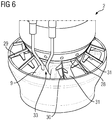
- Figure 6 shows a pilot burner system 2 in accordance with the invention.
- the turbulence elements 29 are arranged in an offset manner with respect to the swirl vanes 9. No turbulence element 29 is provided at the point where the ignition device 33 is located.
- the annulus 28, by means of which the carrier elements 30 of the turbulence elements 29 are connected to one another, can be separated as required during installation.
- Figure 6 also shows that the wings 31 are arranged differently on the carrier elements, depending on their radial position.
Claims (12)
- Brennersystem (2, 3), insbesondere für den Einsatz in einer Gasturbine, mit einem Ringkanal (6, 13) für die Zufuhr von Verbrennungsluft, wobei der Ringkanal (6, 13) durch eine Nabe (18) und ein äußeres Gehäuse gebildet ist und eine Symmetrieachse (12) aufweist, einem in der Nabe (18) angeordneten Brennstoffkanal (4, 5, 19, 20, 21) für die Brennstoffzufuhr, mehreren Verwirbelungselementen (29) zur Erzeugung von stark turbulenter Verbrennungsluft und einem Einlass von Brennstoff (10, 11, 15, 16, 17) aus dem Brennstoffkanal (4, 5, 19, 20, 21) in den Ringkanal (6, 13) abströmseitig von den Verwirbelungselementen (29), wobei sich Trägerelemente (30) der Verwirbelungselemente (29) in radialer Richtung von der Nabe (18) zum äußeren Gehäuse erstrecken und auf den Trägerelementen (30) mindestens je ein Flügel (31) angeordnet ist, wobei die Projektion eines bezogen auf die Symmetrieachse (12) radial außen angeordneten Flügels (31) auf eine Querschnittsfläche des Ringkanals (6, 13) größer ist als die Projektion eines bezogen auf die Symmetrieachse (12) radial innen angeordneten Flügels (31), dadurch gekennzeichnet, dass ein Anstellwinkel der Flügel (31) über den Umfang des Ringkanals (6, 13) oder in radialer Richtung variiert.
- Brennersystem (2, 3) nach Anspruch 1, wobei jedes Trägerelement (30) mindestens zwei Flügel (31) aufweist.
- Brennersystem (2, 3) nach einem der Ansprüche 1 oder 2, wobei jedes Trägerelement (30) Flügelpaare aufweist, bei denen die Flügel (31) gegensinnig gegen die Querschnittsfläche des Ringkanals (6, 13) geneigt angeordnet sind.
- Brennersystem (2, 3) nach einem der vorhergehenden Ansprüche, wobei die Verwirbelungselemente (29) an einem Eintritt in den Ringkanal (6, 13) angeordnet sind.
- Brennersystem (2, 3) nach einem der vorhergehenden Ansprüche, wobei Flächen weiter radial außen angeordneter Flügel (31) größer sind als Flächen weiter radial innen angeordneter Flügel (31).
- Brennersystem (2, 3) nach einem der vorhergehenden Ansprüche, wobei die Flügel (31) sich von den Trägerelementen (30) weg verjüngen und insbesondere eine Trapez- oder Dreiecksform aufweisen.
- Brennersystem (2, 3) nach einem der vorhergehenden Ansprüche, wobei die Verwirbelungselemente (29) nabenseitig über einen Ring (28) miteinander verbunden sind.
- Brennersystem (2, 3) nach einem der vorhergehenden Ansprüche, wobei abströmseitig von den Verwirbelungselementen (29) Drallschaufeln (9, 14) im Ringkanal (6, 13) angeordnet sind.
- Brennersystem (2, 3) nach Anspruch 8, wobei mindestens eine der Drallschaufeln (9, 14) als Hohlschaufel ausgebildet ist, aus der Brennstoff in den Ringkanal (6, 13) einlassbar ist.
- Brennersystem (2) nach einem der vorhergehenden Ansprüche, das als Pilotbrennersystem (2) ausgebildet ist, durch das eine Pilotflamme zur Aufrechterhaltung der Verbrennung erzeugbar ist, wobei die Flügel (31) im Wesentlichen radial innen bis zu einer radialen Mitte auf den Trägerelementen (30) angeordnet sind.
- Brennersystem (3) nach einem der Ansprüche 1 bis 9, das als Hauptbrennersystem (3) ausgebildet ist, wobei die Flügel (31) über eine gesamte radiale Erstreckung der Trägerelemente (30) verteilt auf den Trägerelementen (30) angeordnet sind.
- Brenner (1) mit mindestens einem Brennersystem (2, 3) nach einem der vorhergehenden Ansprüche.
Applications Claiming Priority (2)
| Application Number | Priority Date | Filing Date | Title |
|---|---|---|---|
| US201361756187P | 2013-01-24 | 2013-01-24 | |
| PCT/EP2014/050651 WO2014114533A1 (en) | 2013-01-24 | 2014-01-15 | Burner system having turbulence elements |
Publications (2)
| Publication Number | Publication Date |
|---|---|
| EP2948715A1 EP2948715A1 (de) | 2015-12-02 |
| EP2948715B1 true EP2948715B1 (de) | 2019-04-17 |
Family
ID=49998250
Family Applications (1)
| Application Number | Title | Priority Date | Filing Date |
|---|---|---|---|
| EP14700852.8A Active EP2948715B1 (de) | 2013-01-24 | 2014-01-15 | Brennersystem mit turbulenzelementen |
Country Status (2)
| Country | Link |
|---|---|
| EP (1) | EP2948715B1 (de) |
| WO (1) | WO2014114533A1 (de) |
Families Citing this family (3)
| Publication number | Priority date | Publication date | Assignee | Title |
|---|---|---|---|---|
| WO2015134010A1 (en) * | 2014-03-05 | 2015-09-11 | Siemens Aktiengesellschaft | Combustor inlet flow static mixing system for conditioning air being fed to the combustor in a gas turbine engine |
| DE102015206227A1 (de) * | 2015-04-08 | 2016-10-13 | Siemens Aktiengesellschaft | Brenneranordnung |
| EP4206535A1 (de) * | 2021-12-30 | 2023-07-05 | Ansaldo Energia Switzerland AG | Brenneranordnung mit inline-injektoren |
Citations (3)
| Publication number | Priority date | Publication date | Assignee | Title |
|---|---|---|---|---|
| US3620012A (en) * | 1969-03-21 | 1971-11-16 | Rolls Royce | Gas turbine engine combustion equipment |
| US4134260A (en) * | 1977-10-25 | 1979-01-16 | General Motors Corporation | Afterburner flow mixing means in turbofan jet engine |
| DE102007012790A1 (de) * | 2007-03-16 | 2008-09-18 | Audi Ag | Statischer Mischer für eine Abgasanlage einer Brennkraftmaschine |
Family Cites Families (6)
| Publication number | Priority date | Publication date | Assignee | Title |
|---|---|---|---|---|
| EP0619134B1 (de) * | 1993-04-08 | 1996-12-18 | ABB Management AG | Mischkammer |
| DE59704739D1 (de) | 1996-12-20 | 2001-10-31 | Siemens Ag | Brenner für fluidische brennstoffe |
| JP4508474B2 (ja) * | 2001-06-07 | 2010-07-21 | 三菱重工業株式会社 | 燃焼器 |
| DE60228085D1 (de) | 2002-09-20 | 2008-09-18 | Siemens Ag | Vormischbrenner mit profilierter Luftmassenströmung |
| EP1645807A1 (de) * | 2004-10-11 | 2006-04-12 | Siemens Aktiengesellschaft | Brenner zur Verbrennung eines niederkalorischen Brenngases und Verfahren zum Betrieb eines Brenners |
| US20120024985A1 (en) * | 2010-08-02 | 2012-02-02 | General Electric Company | Integrated fuel nozzle and inlet flow conditioner and related method |
-
2014
- 2014-01-15 WO PCT/EP2014/050651 patent/WO2014114533A1/en active Application Filing
- 2014-01-15 EP EP14700852.8A patent/EP2948715B1/de active Active
Patent Citations (3)
| Publication number | Priority date | Publication date | Assignee | Title |
|---|---|---|---|---|
| US3620012A (en) * | 1969-03-21 | 1971-11-16 | Rolls Royce | Gas turbine engine combustion equipment |
| US4134260A (en) * | 1977-10-25 | 1979-01-16 | General Motors Corporation | Afterburner flow mixing means in turbofan jet engine |
| DE102007012790A1 (de) * | 2007-03-16 | 2008-09-18 | Audi Ag | Statischer Mischer für eine Abgasanlage einer Brennkraftmaschine |
Also Published As
| Publication number | Publication date |
|---|---|
| WO2014114533A1 (en) | 2014-07-31 |
| EP2948715A1 (de) | 2015-12-02 |
Similar Documents
| Publication | Publication Date | Title |
|---|---|---|
| JP6159136B2 (ja) | 差動流を有する複数の管の燃料ノズルを有するシステムおよび方法 | |
| KR100550689B1 (ko) | 가스 터빈의 연소 시스템용 버너 및 연료와 공기의 예비혼합 방법 | |
| JP4934696B2 (ja) | バーナ及び燃焼器 | |
| US20080078183A1 (en) | Liquid fuel enhancement for natural gas swirl stabilized nozzle and method | |
| US20100319353A1 (en) | Multiple Fuel Circuits for Syngas/NG DLN in a Premixed Nozzle | |
| JP4922878B2 (ja) | ガスタービン燃焼器 | |
| US8678301B2 (en) | Stepped swirler for dynamic control | |
| US10125992B2 (en) | Gas turbine combustor with annular flow sleeves for dividing airflow upstream of premixing passages | |
| WO2014055425A1 (en) | Variable length combustor dome extension for improved operability | |
| US10794589B2 (en) | Liquid fuel cartridge for a fuel nozzle | |
| US20170254541A1 (en) | Burner comprising a fluidic oscillator, for a gas turbine, and a gas turbine comprising at least one such burner | |
| US9810432B2 (en) | Method for premixing air with a gaseous fuel and burner arrangement for conducting said method | |
| JP2011196681A (ja) | 予混合一次燃料ノズルアセンブリを有する燃焼器 | |
| CN105318357B (zh) | 用于燃气涡轮发动机燃烧器导流罩的圆锥-平坦隔热罩 | |
| JP2019536976A (ja) | 燃料/空気の混合が改良されたスワーラ、燃焼器アセンブリおよびガスタービン | |
| JP2010060189A (ja) | 燃焼器,燃焼器の燃料供給方法及び燃焼器の燃料ノズル改造方法 | |
| JP5606628B2 (ja) | バーナ装置 | |
| EP2948715B1 (de) | Brennersystem mit turbulenzelementen | |
| CN110440290B (zh) | 用于燃气轮机的微混合喷嘴 | |
| EP2340398B1 (de) | Hauptdrallvorrichtungen mit abwechselnder drallrichtung in magervorgemischten gasturbinenbrennkammern | |
| RU2669439C1 (ru) | Система горелок | |
| JP2020122629A (ja) | バーナ及びこれを備えた燃焼器及びガスタービン | |
| EP3376110B1 (de) | Gasturbinenkraftwerk und verfahren zum betrieb des gasturbinenkraftwerks | |
| JP2008082590A (ja) | ガスタービン燃焼器 | |
| JP2013178003A (ja) | バーナ及びこのバーナを備えたガスタービン燃焼器 |
Legal Events
| Date | Code | Title | Description |
|---|---|---|---|
| PUAI | Public reference made under article 153(3) epc to a published international application that has entered the european phase |
Free format text: ORIGINAL CODE: 0009012 |
|
| 17P | Request for examination filed |
Effective date: 20150716 |
|
| AK | Designated contracting states |
Kind code of ref document: A1 Designated state(s): AL AT BE BG CH CY CZ DE DK EE ES FI FR GB GR HR HU IE IS IT LI LT LU LV MC MK MT NL NO PL PT RO RS SE SI SK SM TR |
|
| AX | Request for extension of the european patent |
Extension state: BA ME |
|
| DAX | Request for extension of the european patent (deleted) | ||
| 17Q | First examination report despatched |
Effective date: 20160802 |
|
| RAP1 | Party data changed (applicant data changed or rights of an application transferred) |
Owner name: SIEMENS AKTIENGESELLSCHAFT |
|
| GRAP | Despatch of communication of intention to grant a patent |
Free format text: ORIGINAL CODE: EPIDOSNIGR1 |
|
| STAA | Information on the status of an ep patent application or granted ep patent |
Free format text: STATUS: GRANT OF PATENT IS INTENDED |
|
| INTG | Intention to grant announced |
Effective date: 20181207 |
|
| GRAS | Grant fee paid |
Free format text: ORIGINAL CODE: EPIDOSNIGR3 |
|
| GRAA | (expected) grant |
Free format text: ORIGINAL CODE: 0009210 |
|
| STAA | Information on the status of an ep patent application or granted ep patent |
Free format text: STATUS: THE PATENT HAS BEEN GRANTED |
|
| AK | Designated contracting states |
Kind code of ref document: B1 Designated state(s): AL AT BE BG CH CY CZ DE DK EE ES FI FR GB GR HR HU IE IS IT LI LT LU LV MC MK MT NL NO PL PT RO RS SE SI SK SM TR |
|
| REG | Reference to a national code |
Ref country code: GB Ref legal event code: FG4D |
|
| REG | Reference to a national code |
Ref country code: CH Ref legal event code: EP |
|
| REG | Reference to a national code |
Ref country code: DE Ref legal event code: R096 Ref document number: 602014044844 Country of ref document: DE |
|
| REG | Reference to a national code |
Ref country code: AT Ref legal event code: REF Ref document number: 1121953 Country of ref document: AT Kind code of ref document: T Effective date: 20190515 Ref country code: IE Ref legal event code: FG4D |
|
| REG | Reference to a national code |
Ref country code: NL Ref legal event code: MP Effective date: 20190417 |
|
| REG | Reference to a national code |
Ref country code: LT Ref legal event code: MG4D |
|
| PG25 | Lapsed in a contracting state [announced via postgrant information from national office to epo] |
Ref country code: NL Free format text: LAPSE BECAUSE OF FAILURE TO SUBMIT A TRANSLATION OF THE DESCRIPTION OR TO PAY THE FEE WITHIN THE PRESCRIBED TIME-LIMIT Effective date: 20190417 |
|
| PG25 | Lapsed in a contracting state [announced via postgrant information from national office to epo] |
Ref country code: SE Free format text: LAPSE BECAUSE OF FAILURE TO SUBMIT A TRANSLATION OF THE DESCRIPTION OR TO PAY THE FEE WITHIN THE PRESCRIBED TIME-LIMIT Effective date: 20190417 Ref country code: ES Free format text: LAPSE BECAUSE OF FAILURE TO SUBMIT A TRANSLATION OF THE DESCRIPTION OR TO PAY THE FEE WITHIN THE PRESCRIBED TIME-LIMIT Effective date: 20190417 Ref country code: LT Free format text: LAPSE BECAUSE OF FAILURE TO SUBMIT A TRANSLATION OF THE DESCRIPTION OR TO PAY THE FEE WITHIN THE PRESCRIBED TIME-LIMIT Effective date: 20190417 Ref country code: FI Free format text: LAPSE BECAUSE OF FAILURE TO SUBMIT A TRANSLATION OF THE DESCRIPTION OR TO PAY THE FEE WITHIN THE PRESCRIBED TIME-LIMIT Effective date: 20190417 Ref country code: AL Free format text: LAPSE BECAUSE OF FAILURE TO SUBMIT A TRANSLATION OF THE DESCRIPTION OR TO PAY THE FEE WITHIN THE PRESCRIBED TIME-LIMIT Effective date: 20190417 Ref country code: PT Free format text: LAPSE BECAUSE OF FAILURE TO SUBMIT A TRANSLATION OF THE DESCRIPTION OR TO PAY THE FEE WITHIN THE PRESCRIBED TIME-LIMIT Effective date: 20190817 Ref country code: HR Free format text: LAPSE BECAUSE OF FAILURE TO SUBMIT A TRANSLATION OF THE DESCRIPTION OR TO PAY THE FEE WITHIN THE PRESCRIBED TIME-LIMIT Effective date: 20190417 Ref country code: NO Free format text: LAPSE BECAUSE OF FAILURE TO SUBMIT A TRANSLATION OF THE DESCRIPTION OR TO PAY THE FEE WITHIN THE PRESCRIBED TIME-LIMIT Effective date: 20190717 |
|
| PG25 | Lapsed in a contracting state [announced via postgrant information from national office to epo] |
Ref country code: PL Free format text: LAPSE BECAUSE OF FAILURE TO SUBMIT A TRANSLATION OF THE DESCRIPTION OR TO PAY THE FEE WITHIN THE PRESCRIBED TIME-LIMIT Effective date: 20190417 Ref country code: GR Free format text: LAPSE BECAUSE OF FAILURE TO SUBMIT A TRANSLATION OF THE DESCRIPTION OR TO PAY THE FEE WITHIN THE PRESCRIBED TIME-LIMIT Effective date: 20190718 Ref country code: LV Free format text: LAPSE BECAUSE OF FAILURE TO SUBMIT A TRANSLATION OF THE DESCRIPTION OR TO PAY THE FEE WITHIN THE PRESCRIBED TIME-LIMIT Effective date: 20190417 Ref country code: BG Free format text: LAPSE BECAUSE OF FAILURE TO SUBMIT A TRANSLATION OF THE DESCRIPTION OR TO PAY THE FEE WITHIN THE PRESCRIBED TIME-LIMIT Effective date: 20190717 Ref country code: RS Free format text: LAPSE BECAUSE OF FAILURE TO SUBMIT A TRANSLATION OF THE DESCRIPTION OR TO PAY THE FEE WITHIN THE PRESCRIBED TIME-LIMIT Effective date: 20190417 |
|
| REG | Reference to a national code |
Ref country code: AT Ref legal event code: MK05 Ref document number: 1121953 Country of ref document: AT Kind code of ref document: T Effective date: 20190417 |
|
| PG25 | Lapsed in a contracting state [announced via postgrant information from national office to epo] |
Ref country code: IS Free format text: LAPSE BECAUSE OF FAILURE TO SUBMIT A TRANSLATION OF THE DESCRIPTION OR TO PAY THE FEE WITHIN THE PRESCRIBED TIME-LIMIT Effective date: 20190817 |
|
| REG | Reference to a national code |
Ref country code: DE Ref legal event code: R097 Ref document number: 602014044844 Country of ref document: DE |
|
| PG25 | Lapsed in a contracting state [announced via postgrant information from national office to epo] |
Ref country code: DK Free format text: LAPSE BECAUSE OF FAILURE TO SUBMIT A TRANSLATION OF THE DESCRIPTION OR TO PAY THE FEE WITHIN THE PRESCRIBED TIME-LIMIT Effective date: 20190417 Ref country code: AT Free format text: LAPSE BECAUSE OF FAILURE TO SUBMIT A TRANSLATION OF THE DESCRIPTION OR TO PAY THE FEE WITHIN THE PRESCRIBED TIME-LIMIT Effective date: 20190417 Ref country code: EE Free format text: LAPSE BECAUSE OF FAILURE TO SUBMIT A TRANSLATION OF THE DESCRIPTION OR TO PAY THE FEE WITHIN THE PRESCRIBED TIME-LIMIT Effective date: 20190417 Ref country code: RO Free format text: LAPSE BECAUSE OF FAILURE TO SUBMIT A TRANSLATION OF THE DESCRIPTION OR TO PAY THE FEE WITHIN THE PRESCRIBED TIME-LIMIT Effective date: 20190417 Ref country code: CZ Free format text: LAPSE BECAUSE OF FAILURE TO SUBMIT A TRANSLATION OF THE DESCRIPTION OR TO PAY THE FEE WITHIN THE PRESCRIBED TIME-LIMIT Effective date: 20190417 Ref country code: SK Free format text: LAPSE BECAUSE OF FAILURE TO SUBMIT A TRANSLATION OF THE DESCRIPTION OR TO PAY THE FEE WITHIN THE PRESCRIBED TIME-LIMIT Effective date: 20190417 |
|
| PLBE | No opposition filed within time limit |
Free format text: ORIGINAL CODE: 0009261 |
|
| STAA | Information on the status of an ep patent application or granted ep patent |
Free format text: STATUS: NO OPPOSITION FILED WITHIN TIME LIMIT |
|
| PG25 | Lapsed in a contracting state [announced via postgrant information from national office to epo] |
Ref country code: SM Free format text: LAPSE BECAUSE OF FAILURE TO SUBMIT A TRANSLATION OF THE DESCRIPTION OR TO PAY THE FEE WITHIN THE PRESCRIBED TIME-LIMIT Effective date: 20190417 |
|
| 26N | No opposition filed |
Effective date: 20200120 |
|
| PG25 | Lapsed in a contracting state [announced via postgrant information from national office to epo] |
Ref country code: TR Free format text: LAPSE BECAUSE OF FAILURE TO SUBMIT A TRANSLATION OF THE DESCRIPTION OR TO PAY THE FEE WITHIN THE PRESCRIBED TIME-LIMIT Effective date: 20190417 |
|
| PG25 | Lapsed in a contracting state [announced via postgrant information from national office to epo] |
Ref country code: SI Free format text: LAPSE BECAUSE OF FAILURE TO SUBMIT A TRANSLATION OF THE DESCRIPTION OR TO PAY THE FEE WITHIN THE PRESCRIBED TIME-LIMIT Effective date: 20190417 |
|
| PG25 | Lapsed in a contracting state [announced via postgrant information from national office to epo] |
Ref country code: MC Free format text: LAPSE BECAUSE OF FAILURE TO SUBMIT A TRANSLATION OF THE DESCRIPTION OR TO PAY THE FEE WITHIN THE PRESCRIBED TIME-LIMIT Effective date: 20190417 |
|
| REG | Reference to a national code |
Ref country code: CH Ref legal event code: PL |
|
| GBPC | Gb: european patent ceased through non-payment of renewal fee |
Effective date: 20200115 |
|
| REG | Reference to a national code |
Ref country code: BE Ref legal event code: MM Effective date: 20200131 |
|
| PG25 | Lapsed in a contracting state [announced via postgrant information from national office to epo] |
Ref country code: GB Free format text: LAPSE BECAUSE OF NON-PAYMENT OF DUE FEES Effective date: 20200115 Ref country code: LU Free format text: LAPSE BECAUSE OF NON-PAYMENT OF DUE FEES Effective date: 20200115 Ref country code: FR Free format text: LAPSE BECAUSE OF NON-PAYMENT OF DUE FEES Effective date: 20200131 |
|
| PG25 | Lapsed in a contracting state [announced via postgrant information from national office to epo] |
Ref country code: CH Free format text: LAPSE BECAUSE OF NON-PAYMENT OF DUE FEES Effective date: 20200131 Ref country code: BE Free format text: LAPSE BECAUSE OF NON-PAYMENT OF DUE FEES Effective date: 20200131 Ref country code: LI Free format text: LAPSE BECAUSE OF NON-PAYMENT OF DUE FEES Effective date: 20200131 |
|
| REG | Reference to a national code |
Ref country code: DE Ref legal event code: R081 Ref document number: 602014044844 Country of ref document: DE Owner name: SIEMENS ENERGY GLOBAL GMBH & CO. KG, DE Free format text: FORMER OWNER: SIEMENS AKTIENGESELLSCHAFT, 80333 MUENCHEN, DE |
|
| PG25 | Lapsed in a contracting state [announced via postgrant information from national office to epo] |
Ref country code: IE Free format text: LAPSE BECAUSE OF NON-PAYMENT OF DUE FEES Effective date: 20200115 |
|
| PG25 | Lapsed in a contracting state [announced via postgrant information from national office to epo] |
Ref country code: MT Free format text: LAPSE BECAUSE OF FAILURE TO SUBMIT A TRANSLATION OF THE DESCRIPTION OR TO PAY THE FEE WITHIN THE PRESCRIBED TIME-LIMIT Effective date: 20190417 Ref country code: CY Free format text: LAPSE BECAUSE OF FAILURE TO SUBMIT A TRANSLATION OF THE DESCRIPTION OR TO PAY THE FEE WITHIN THE PRESCRIBED TIME-LIMIT Effective date: 20190417 |
|
| PG25 | Lapsed in a contracting state [announced via postgrant information from national office to epo] |
Ref country code: MK Free format text: LAPSE BECAUSE OF FAILURE TO SUBMIT A TRANSLATION OF THE DESCRIPTION OR TO PAY THE FEE WITHIN THE PRESCRIBED TIME-LIMIT Effective date: 20190417 |
|
| PGFP | Annual fee paid to national office [announced via postgrant information from national office to epo] |
Ref country code: IT Payment date: 20230126 Year of fee payment: 10 |
|
| PGFP | Annual fee paid to national office [announced via postgrant information from national office to epo] |
Ref country code: DE Payment date: 20240129 Year of fee payment: 11 |