EP2947575A2 - Elektronische vorrichtung und verfahren zur umschaltung zwischen einem normastrommodus und einem stromsparmodus einer elektronischen vorrichtung - Google Patents
Elektronische vorrichtung und verfahren zur umschaltung zwischen einem normastrommodus und einem stromsparmodus einer elektronischen vorrichtung Download PDFInfo
- Publication number
- EP2947575A2 EP2947575A2 EP15168846.2A EP15168846A EP2947575A2 EP 2947575 A2 EP2947575 A2 EP 2947575A2 EP 15168846 A EP15168846 A EP 15168846A EP 2947575 A2 EP2947575 A2 EP 2947575A2
- Authority
- EP
- European Patent Office
- Prior art keywords
- electronic device
- host
- status
- power saving
- saving mode
- Prior art date
- Legal status (The legal status is an assumption and is not a legal conclusion. Google has not performed a legal analysis and makes no representation as to the accuracy of the status listed.)
- Withdrawn
Links
Images


Classifications
-
- G—PHYSICS
- G06—COMPUTING OR CALCULATING; COUNTING
- G06F—ELECTRIC DIGITAL DATA PROCESSING
- G06F1/00—Details not covered by groups G06F3/00 - G06F13/00 and G06F21/00
- G06F1/26—Power supply means, e.g. regulation thereof
- G06F1/32—Means for saving power
- G06F1/3203—Power management, i.e. event-based initiation of a power-saving mode
- G06F1/3234—Power saving characterised by the action undertaken
- G06F1/325—Power saving in peripheral device
-
- G—PHYSICS
- G06—COMPUTING OR CALCULATING; COUNTING
- G06F—ELECTRIC DIGITAL DATA PROCESSING
- G06F1/00—Details not covered by groups G06F3/00 - G06F13/00 and G06F21/00
- G06F1/26—Power supply means, e.g. regulation thereof
- G06F1/32—Means for saving power
- G06F1/3203—Power management, i.e. event-based initiation of a power-saving mode
- G06F1/3206—Monitoring of events, devices or parameters that trigger a change in power modality
-
- G—PHYSICS
- G06—COMPUTING OR CALCULATING; COUNTING
- G06F—ELECTRIC DIGITAL DATA PROCESSING
- G06F1/00—Details not covered by groups G06F3/00 - G06F13/00 and G06F21/00
- G06F1/26—Power supply means, e.g. regulation thereof
- G06F1/32—Means for saving power
- G06F1/3203—Power management, i.e. event-based initiation of a power-saving mode
- G06F1/3206—Monitoring of events, devices or parameters that trigger a change in power modality
- G06F1/3209—Monitoring remote activity, e.g. over telephone lines or network connections
-
- G—PHYSICS
- G06—COMPUTING OR CALCULATING; COUNTING
- G06F—ELECTRIC DIGITAL DATA PROCESSING
- G06F1/00—Details not covered by groups G06F3/00 - G06F13/00 and G06F21/00
- G06F1/26—Power supply means, e.g. regulation thereof
- G06F1/32—Means for saving power
- G06F1/3203—Power management, i.e. event-based initiation of a power-saving mode
- G06F1/3206—Monitoring of events, devices or parameters that trigger a change in power modality
- G06F1/3215—Monitoring of peripheral devices
-
- G—PHYSICS
- G06—COMPUTING OR CALCULATING; COUNTING
- G06F—ELECTRIC DIGITAL DATA PROCESSING
- G06F1/00—Details not covered by groups G06F3/00 - G06F13/00 and G06F21/00
- G06F1/26—Power supply means, e.g. regulation thereof
- G06F1/32—Means for saving power
- G06F1/3203—Power management, i.e. event-based initiation of a power-saving mode
- G06F1/3234—Power saving characterised by the action undertaken
- G06F1/325—Power saving in peripheral device
- G06F1/3284—Power saving in printer
-
- G—PHYSICS
- G06—COMPUTING OR CALCULATING; COUNTING
- G06F—ELECTRIC DIGITAL DATA PROCESSING
- G06F13/00—Interconnection of, or transfer of information or other signals between, memories, input/output devices or central processing units
- G06F13/38—Information transfer, e.g. on bus
- G06F13/40—Bus structure
- G06F13/4063—Device-to-bus coupling
- G06F13/4068—Electrical coupling
- G06F13/4081—Live connection to bus, e.g. hot-plugging
-
- G—PHYSICS
- G06—COMPUTING OR CALCULATING; COUNTING
- G06F—ELECTRIC DIGITAL DATA PROCESSING
- G06F2213/00—Indexing scheme relating to interconnection of, or transfer of information or other signals between, memories, input/output devices or central processing units
- G06F2213/0042—Universal serial bus [USB]
-
- Y—GENERAL TAGGING OF NEW TECHNOLOGICAL DEVELOPMENTS; GENERAL TAGGING OF CROSS-SECTIONAL TECHNOLOGIES SPANNING OVER SEVERAL SECTIONS OF THE IPC; TECHNICAL SUBJECTS COVERED BY FORMER USPC CROSS-REFERENCE ART COLLECTIONS [XRACs] AND DIGESTS
- Y02—TECHNOLOGIES OR APPLICATIONS FOR MITIGATION OR ADAPTATION AGAINST CLIMATE CHANGE
- Y02D—CLIMATE CHANGE MITIGATION TECHNOLOGIES IN INFORMATION AND COMMUNICATION TECHNOLOGIES [ICT], I.E. INFORMATION AND COMMUNICATION TECHNOLOGIES AIMING AT THE REDUCTION OF THEIR OWN ENERGY USE
- Y02D10/00—Energy efficient computing, e.g. low power processors, power management or thermal management
-
- Y—GENERAL TAGGING OF NEW TECHNOLOGICAL DEVELOPMENTS; GENERAL TAGGING OF CROSS-SECTIONAL TECHNOLOGIES SPANNING OVER SEVERAL SECTIONS OF THE IPC; TECHNICAL SUBJECTS COVERED BY FORMER USPC CROSS-REFERENCE ART COLLECTIONS [XRACs] AND DIGESTS
- Y02—TECHNOLOGIES OR APPLICATIONS FOR MITIGATION OR ADAPTATION AGAINST CLIMATE CHANGE
- Y02D—CLIMATE CHANGE MITIGATION TECHNOLOGIES IN INFORMATION AND COMMUNICATION TECHNOLOGIES [ICT], I.E. INFORMATION AND COMMUNICATION TECHNOLOGIES AIMING AT THE REDUCTION OF THEIR OWN ENERGY USE
- Y02D30/00—Reducing energy consumption in communication networks
- Y02D30/50—Reducing energy consumption in communication networks in wire-line communication networks, e.g. low power modes or reduced link rate
Definitions
- the present invention relates to electronic devices connectable to a host computer through a universal serial bus (USB).
- the present invention further relates to a method for switching an electronic device connected to a host computer through a USB cable between a normal power mode and a power saving mode.
- USBs universal serial buses
- PC personal computer
- USB devices peripheral devices
- a peripheral device connected to a host computer through a USB receives a status request issued by the host computer at a fixed time interval. In response to the status request, the peripheral device needs to issue a response indicating the status of the peripheral device. Therefore, the peripheral device cannot stay continuously in the power saving mode for a long time.
- the following describes one example of a system that solves the above problem and allows peripheral devices to stay continuously in power saving mode for a long time.
- the printer informs a host computer about the switchable status.
- the host computer suspends a specific USB thereof to which the printer is connected.
- the host computer transmits no further status request to the printer.
- the printer connected to the USB port receives no further status request from the host computer. This allows the printer to stay continuously in the power saving mode for a long time.
- An electronic device includes a transmission-reception section, a pull-up resistor, a switch, and a control section.
- the transmission-reception section communicates with a host through a USB signal line that is for connection with the host.
- the pull-up resistor pulls up a potential of the USB signal line to a predetermined level so as to allow the host to detect a speed of the communication.
- the switch enables or disables the pull-up by the pull-up resistor.
- the control section switches the electronic device between a normal power mode and a power saving mode. In response to a status request received from the host in the normal power mode, the transmission-reception section transmits to the host a status response.
- the status response transmitted by the transmission-reception section indicates that the electronic device is in the switchable status.
- the control section performs the switching to the power saving mode after transmission of the status request by the host is suspended upon receipt of the status response by the host, performs the switching to the normal power mode in response to occurrence of a specific event within the electronic device in the power saving mode, and controls the switch.
- the switch Under control of the control section, the switch disables the pull-up to inform the host that the connection is disconnected, and enables the pull-up to inform the host that the connection is re-established so as to cause the host to resume transmission of the status request.
- a method for switching an electronic device connected to a host computer through a USB cable between a normal power mode and a power saving mode comprises, when the electronic device is in the normal power mode, the steps of receiving a status request transmitted form the host to the electronic device by a transmission-reception section, transmitting a response indicating that the electronic device is in a status switchable to the power saving mode to the host, when the electronic device is in the status switchable to the power saving mode, receiving the status response in a control section of a host, suspending transmission of status request in the host system and switching the electronic device in a power saving mode; when the electronic device is in the power saving mode, the method further comprises the step of resuming the normal power mode, when a specific event occurs, wherein a control section of the electronic device controls the switching of the electronic device between the normal power mode and the power saving mode and the switch.
- a further aspect of the present invention relates to an embodiment wherein the electronic device is a printer, wherein the status in which the electronic device (10) is switchable to the power saving mode refers to a status in which no print job or user operation has occurred for a predetermined time period.
- the step of resuming the normal power mode comprises the steps of informing the host that the electronic device has returned to the normal power mode, performing a USB connection process between the electronic device and the host, resuming transmission of status request in the host system, receiving a status request from the host, and transmitting a status response to the host.
- the step of informing the host that the electronic device has returned to normal power mode comprises turning off a switch, thereby disabling a pull up of a potential of a signal line D+ or a signal line D- such that the host detects a decreased potential of the signal line D+ or the signal line D-and recognizes that the USB connection is disconnected; and turning the switch back on , thereby re-enabling the pull up of the potential of the signal line D+ or the signal line D- such that the host recognizes that the USB connection is re-established, wherein a pull-up resistor pulls up the potential of the signal line D+ or the signal line D- to a predetermined level so as to allow the host to detect a speed of communication
- a further aspect of the present invention relates to the specific event being a user's operation on an operation panel of the printer or, preferably, a reception of a print request from a computer connected over LAN.
- USB in the present embodiment is compliant with the USB specification 2.0 unless otherwise specified.
- USB specification may be USB 3.0 or a later version than USB 3.0.
- USB port to which the USB device is connected is suspended.
- the host computer transmits no status request to the USB device while the USB port is suspended.
- FIG. 1 is a diagram showing an electronic device 10 of the present invention.
- the host computer may be referred to as a USB host
- the electronic device 10 may be referred to as a USB device.
- the electronic device 10 is a peripheral device of the host computer.
- the electronic device 10 is connected to the host computer (serving as a host) through a USB cable 21 (serving as a USB signal line).
- the electronic device 10 may for example be a printer.
- the electronic device 10 includes a transmission-reception section 11, a switch 12, a pull-up resistor 13, and a control section 14.
- the USB cable 21 includes a signal line D+ and signal line D-.
- the USB cable 21 is used to connect the electronic device 10 to the host computer.
- the transmission-reception section 11 performs signal transmission to and from the host computer using the signal lines D+ and D- in accordance with the USB specification. In other words, the transmission-reception section 11 communicates with the host computer through the signal lines D+ and D-.
- the electronic device 10 receives a status request from the host computer. In response to a status request received while in a normal power mode, the transmission-reception section 11 transmits a status response to the host computer.
- a "status response" transmitted to the host computer indicates the status of the USB device connected to the host computer through a USB connection. The "status" indicates the state of the USB device.
- a status response that the electronic device 10 transmits is information indicating that the electronic device 10 is in the state switchable to the power saving mode.
- the transmission-reception section 11 transmits a status response indicating the switchable status.
- the pull-up resistor 13 allows the host computer to detect the speed of communication with the electronic device 10. More specifically, the control section 14 controls the pull-up resistor 13 to pull up the potential of the signal line D+ or D- to a predetermined level in order to inform the host computer about the transfer rate of the electronic device 10.
- the transfer rate refers to the speed at which the transmission-reception section 11 transmits and receives signals with respect to the host computer. That is, the transfer rate refers to the speed at which the transmission-reception section 11 communicates with the host computer.
- the electronic device 10 informs the host computer that the electronic device 10 is ready to communicate at a full or high transmission rate.
- the electronic device 10 is not limited to this configuration and the pull-up resistor 13 may pull up the potential of the signal line D- instead.
- the switch 12 is connected in series with the signal line D+ or D- that is to be pulled up and the pull-up resistor 13.
- the switch 12 enables and disables the pull-up of the signal line D+ or D- under the control of the control section 14. That is, instructions to enable and disable the pull-up are issued by the control section 14.
- the control section 14 performs overall control of the electronic device 10 and also controls the transmission-reception section 11 to communicate with the host computer and the switch 12 to enable or disable the pull-up.
- the overall control of the electronic device 10 includes the control of the switching of the electronic device 10 between the power saving mode and the normal power mode.
- the host computer transmits a status request to the electronic device 10.
- the host computer connected to the electronic device 10 using a USB suspends transmission of a status request when a response from the electronic device 10 indicates that the electronic device 10 is in the status switchable to the power saving mode.
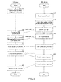
- FIG. 2 is a flowchart illustrating the flow of processing performed by the host computer and the electronic device 10 when the electronic device 10 switches from the normal power mode to the power saving mode.
- the host computer is referred to as a USB host and the electronic device 10 is referred to as a USB device.
- Step S1 the control section of the USB host transmits a status request to the USB device.
- control section 14 of the USB device receives the status request through the transmission-reception section 11 (Step S2).
- the control section 14 of the USB device controls the transmission-reception section 11 to transmit a response indicating that the USB devices is in the status switchable to the power saving mode (Step S3).
- the status in which the USB device is switchable to the power saving mode refers to a status in which no print job or user operation has occurred for a predetermined time period.
- control section of the USB host receives the status response indicating that the USB device is switchable to the power saving mode (Step S4).
- Step S5 the control section of the USB host suspends transmission of a status request to the USB device.
- the control section 14 of the USB device switches the USB device to the power saving mode after the control section of the USB host suspends transmission of a status request (Step S6). Since no status request is received from the USB host, there is no need for the control section 14 to transmit a status response. This allows the USB device to stay continuously in the power saving mode.
- the control section 14 of the USB device determines that the USB host has suspended transmission of a status request when, for example, no status request is received from the control section of the USB host for a predetermined time period.
- FIG. 3 is a flowchart illustrating the flow of processing performed when the host computer (USB host) resumes transmission of a status request to the electronic device 10 (USB device).
- Step S10 The following description is given on precondition that the USB device is in the power saving mode and thus transmission of a status request to the USB device by the USB host is currently suspended.
- an event triggering the USB device to return from the power saving mode to the normal power mode occurs within the electronic device 10 (electronic device) (Step S11).
- the event may be a user's operation on an operation panel of the printer, reception of a print request from a PC connected over LAN, and so on.
- the LAN connection differs from the USB connection.
- the control section 14 of the USB device returns the USB device from the power saving mode to the normal power mode (Step S12). More specifically, in response to occurrence of a specific event within the electronic device 10 in the power saving mode, the control section 14 switches the electronic device 10 into the normal power mode.
- the control section 14 of the USB device informs the USB host that the USB device has returned to the normal power mode. More specifically, the control section 14 controls the switch 12 to turn off, thereby disabling the pull-up of the signal line D+ or D- (Step S13). As a result, the potential of the signal line D+ or D- having been pulled up is decreased.
- control section of the USB host detects that the potential of the signal line D+ or D- has decreased, and thus recognizes that the USB connection with the USB device is disconnected (Step S14).
- control section 14 of the USB device controls the switch 12 to turn on, thereby re-enabling the pull up of the signal line D+ or D- (Step S15).
- the control section of the USB host detects the pull-up of the signal line D+ or D- and thus recognizes that the USB connection is re-established. In short, the control section of the USB host recognizes that a new USB connection is established (Step S16).
- control section 14 of the USB device and the control section of the USB host perform a connection process in the same manner as when a USB cable is connected (Steps S17 and S18).
- Step S19 Upon completion of the connection process, the control section of the USB host resumes transmission of a status request to the USB device (Step S19).
- the transmission-reception section 11 of the USB device receives the status request (Step S20).
- control section 14 of the USB device collects information about the USB device (Step S21) and transmits the information as the status response (Step S21).
- control section of the USB host receives the status response from the USB device (Step S22).
- the USB device can inform occurrence of an event to the host computer without receiving a status request from the host computer.
Landscapes
- Engineering & Computer Science (AREA)
- Theoretical Computer Science (AREA)
- General Engineering & Computer Science (AREA)
- Physics & Mathematics (AREA)
- General Physics & Mathematics (AREA)
- Computer Hardware Design (AREA)
- Power Sources (AREA)
- Information Transfer Systems (AREA)
- Accessory Devices And Overall Control Thereof (AREA)
- Communication Control (AREA)
Applications Claiming Priority (1)
| Application Number | Priority Date | Filing Date | Title |
|---|---|---|---|
| JP2014106631A JP6014627B2 (ja) | 2014-05-23 | 2014-05-23 | 電子機器の電力モード切り替えシステム |
Publications (2)
| Publication Number | Publication Date |
|---|---|
| EP2947575A2 true EP2947575A2 (de) | 2015-11-25 |
| EP2947575A3 EP2947575A3 (de) | 2015-12-09 |
Family
ID=53396196
Family Applications (1)
| Application Number | Title | Priority Date | Filing Date |
|---|---|---|---|
| EP15168846.2A Withdrawn EP2947575A3 (de) | 2014-05-23 | 2015-05-22 | Elektronische vorrichtung und verfahren zur umschaltung zwischen einem normastrommodus und einem stromsparmodus einer elektronischen vorrichtung |
Country Status (4)
| Country | Link |
|---|---|
| US (1) | US9552048B2 (de) |
| EP (1) | EP2947575A3 (de) |
| JP (1) | JP6014627B2 (de) |
| CN (1) | CN105094715B (de) |
Families Citing this family (4)
| Publication number | Priority date | Publication date | Assignee | Title |
|---|---|---|---|---|
| ES2565197T3 (es) * | 2012-05-30 | 2016-04-01 | Uvan Holding Ab | Mecanismo de basculamiento para un recipiente |
| JP7009866B2 (ja) * | 2017-09-21 | 2022-01-26 | セイコーエプソン株式会社 | 電子機器、通信処理方法及びプログラム |
| CN111400225B (zh) * | 2019-01-02 | 2021-10-22 | 瑞昱半导体股份有限公司 | Usb转接电路 |
| US11741023B1 (en) * | 2022-02-09 | 2023-08-29 | Pixart Imaging Inc. | Pointing device and method capable of correcting its USB state by monitoring voltage/state of USB communication interface |
Family Cites Families (13)
| Publication number | Priority date | Publication date | Assignee | Title |
|---|---|---|---|---|
| JP2001067156A (ja) * | 1999-08-27 | 2001-03-16 | Canon Inc | コンピュータ周辺機器及びその制御方法、撮像装置並びに記憶媒体 |
| US6662301B1 (en) | 1999-08-27 | 2003-12-09 | Canon Kabushiki Kaisha | Computer peripheral device, its control method, image pickup device, storage medium, computer system, and computer |
| JP3795712B2 (ja) * | 1999-09-02 | 2006-07-12 | アルプス電気株式会社 | 周辺機器の接続装置 |
| JP2003263245A (ja) * | 2002-03-07 | 2003-09-19 | Fuji Xerox Co Ltd | Usb装置 |
| JP4529441B2 (ja) * | 2004-01-05 | 2010-08-25 | 富士ゼロックス株式会社 | 画像処理装置およびホスト装置 |
| TW200513865A (en) * | 2004-09-17 | 2005-04-16 | Via Tech Inc | USB control circuit with function of switching between host mode and controlled mode and its operating method |
| JP2008084230A (ja) * | 2006-09-28 | 2008-04-10 | Nec Corp | Usbデバイス装置のサスペンド制御方法、usbデバイス装置及びサスペンド制御プログラム |
| US7644217B2 (en) * | 2007-03-02 | 2010-01-05 | Microchip Technology Incorporated | Detecting connection to a USB host or hub without using an extra status input |
| JP2010094942A (ja) * | 2008-10-20 | 2010-04-30 | Canon Inc | インクジェット記録システム及びインクジェット記録装置 |
| US8432182B2 (en) * | 2009-03-30 | 2013-04-30 | Analog Devices, Inc. | USB isolator with advanced control features |
| US8332676B2 (en) * | 2009-09-24 | 2012-12-11 | Intel Mobile Communications GmbH | Methods of preparing a power saving state, universal serial bus device and universal serial bus host |
| JP2011134186A (ja) * | 2009-12-25 | 2011-07-07 | Seiko Epson Corp | Usbデバイス装置 |
| JP5549275B2 (ja) * | 2010-02-26 | 2014-07-16 | コニカミノルタ株式会社 | 操作装置、デバイス装置 |
-
2014
- 2014-05-23 JP JP2014106631A patent/JP6014627B2/ja not_active Expired - Fee Related
-
2015
- 2015-05-22 EP EP15168846.2A patent/EP2947575A3/de not_active Withdrawn
- 2015-05-22 CN CN201510264732.6A patent/CN105094715B/zh not_active Expired - Fee Related
- 2015-05-22 US US14/720,039 patent/US9552048B2/en not_active Expired - Fee Related
Non-Patent Citations (1)
| Title |
|---|
| None |
Also Published As
| Publication number | Publication date |
|---|---|
| CN105094715A (zh) | 2015-11-25 |
| US20150338897A1 (en) | 2015-11-26 |
| EP2947575A3 (de) | 2015-12-09 |
| JP6014627B2 (ja) | 2016-10-25 |
| US9552048B2 (en) | 2017-01-24 |
| CN105094715B (zh) | 2018-09-18 |
| JP2015222505A (ja) | 2015-12-10 |
Similar Documents
| Publication | Publication Date | Title |
|---|---|---|
| US7631200B2 (en) | Host apparatus, device, and method for controlling communication system | |
| US10565145B2 (en) | Felxconnect disconnect detection | |
| US9069540B2 (en) | Information handling system adaptive high performance power delivery | |
| EP1685496B1 (de) | Schnittstelle für die serielle datenkommunikation | |
| US20070028127A1 (en) | Universal serial bus system, and method of driving the same | |
| JP6024288B2 (ja) | 情報処理システム及び外部機器 | |
| WO2008087565A1 (en) | Method and apparatus for usb/otg connection providing active hnp requests and saving host power | |
| US9940277B2 (en) | Multi-channel peripheral interconnect supporting simultaneous video and bus protocols | |
| US9552048B2 (en) | Electronic system in which USB device can inform occurrence of event to host device without receiving status request from host device | |
| EP3018556A1 (de) | System zur steuerung der peripheriegeräten an eine docking-station | |
| US20190286202A1 (en) | System, electronic device, and charge controlling method | |
| US20140111825A1 (en) | Data printing method and system using the same | |
| EP2972919B1 (de) | Vorrichtungen und verfahren zur aktivierung einer usb-kommunikation über erweiterungsmedien | |
| CN101937413A (zh) | 一种i2c总线的通信方法 | |
| JP2001067156A5 (ja) | コンピュータ周辺機器及びその制御方法、撮像装置及びその制御方法並びにコンピュータ可読記憶媒体 | |
| EP3239831A1 (de) | Informationsverarbeitungsvorrichtung und informationsverarbeitungsverfahren | |
| US20060236139A1 (en) | Method for transmitting the system command of a computer system | |
| US7506082B2 (en) | Data transferring system using USB and method thereof | |
| JP2006330770A (ja) | Usbホスト装置 | |
| JP4497587B2 (ja) | コンピュータ・システム、コンピュータ、メッセージ処理方法及びコンピュータ可読記憶媒体 | |
| CN103207850A (zh) | 外接设备,异质设备的传输系统与其方法扩展功能 | |
| CN203217562U (zh) | 外接设备与异质设备的传输系统 | |
| JP2005352942A (ja) | Usb機器、ホスト装置、及びusb接続システム | |
| JP2006227867A (ja) | Usbデバイスおよびusbホスト | |
| JP4476010B2 (ja) | シリアル通信処理装置 |
Legal Events
| Date | Code | Title | Description |
|---|---|---|---|
| PUAL | Search report despatched |
Free format text: ORIGINAL CODE: 0009013 |
|
| PUAI | Public reference made under article 153(3) epc to a published international application that has entered the european phase |
Free format text: ORIGINAL CODE: 0009012 |
|
| AK | Designated contracting states |
Kind code of ref document: A2 Designated state(s): AL AT BE BG CH CY CZ DE DK EE ES FI FR GB GR HR HU IE IS IT LI LT LU LV MC MK MT NL NO PL PT RO RS SE SI SK SM TR |
|
| AX | Request for extension of the european patent |
Extension state: BA ME |
|
| AK | Designated contracting states |
Kind code of ref document: A3 Designated state(s): AL AT BE BG CH CY CZ DE DK EE ES FI FR GB GR HR HU IE IS IT LI LT LU LV MC MK MT NL NO PL PT RO RS SE SI SK SM TR |
|
| AX | Request for extension of the european patent |
Extension state: BA ME |
|
| RIC1 | Information provided on ipc code assigned before grant |
Ipc: G06F 13/40 20060101AFI20151105BHEP Ipc: G06F 1/32 20060101ALI20151105BHEP |
|
| 17P | Request for examination filed |
Effective date: 20160518 |
|
| RBV | Designated contracting states (corrected) |
Designated state(s): AL AT BE BG CH CY CZ DE DK EE ES FI FR GB GR HR HU IE IS IT LI LT LU LV MC MK MT NL NO PL PT RO RS SE SI SK SM TR |
|
| 17Q | First examination report despatched |
Effective date: 20180912 |
|
| STAA | Information on the status of an ep patent application or granted ep patent |
Free format text: STATUS: THE APPLICATION HAS BEEN WITHDRAWN |
|
| 18W | Application withdrawn |
Effective date: 20200720 |