EP2947539B1 - Mobiles Endgerät vom Uhrentyp und mobiles Endgerätesystem damit - Google Patents
Mobiles Endgerät vom Uhrentyp und mobiles Endgerätesystem damit Download PDFInfo
- Publication number
- EP2947539B1 EP2947539B1 EP15150301.8A EP15150301A EP2947539B1 EP 2947539 B1 EP2947539 B1 EP 2947539B1 EP 15150301 A EP15150301 A EP 15150301A EP 2947539 B1 EP2947539 B1 EP 2947539B1
- Authority
- EP
- European Patent Office
- Prior art keywords
- mobile terminal
- coupling member
- watch
- type mobile
- contact pin
- Prior art date
- Legal status (The legal status is an assumption and is not a legal conclusion. Google has not performed a legal analysis and makes no representation as to the accuracy of the status listed.)
- Not-in-force
Links
Images




Classifications
-
- G—PHYSICS
- G06—COMPUTING OR CALCULATING; COUNTING
- G06F—ELECTRIC DIGITAL DATA PROCESSING
- G06F1/00—Details not covered by groups G06F3/00 - G06F13/00 and G06F21/00
- G06F1/16—Constructional details or arrangements
- G06F1/1613—Constructional details or arrangements for portable computers
- G06F1/163—Wearable computers, e.g. on a belt
Definitions
- This specification relates to a mobile terminal, and more particularly, a watch-type mobile terminal configured to be wearable on a user's wrist, and a mobile terminal system having the same.
- Terminals may be generally classified as mobile/portable terminals or stationary terminals according to their mobility. Mobile terminals may also be classified as handheld terminals or vehicle mounted terminals according to whether or not a user can directly carry the terminal.
- Mobile terminals have become increasingly more functional. Examples of such functions include data and voice communications, capturing images and video via a camera, recording audio, playing music files via a speaker system, and displaying images and video on a display. Some mobile terminals include additional functionality which supports game playing, while other terminals are configured as multimedia players. More recently, mobile terminals have been configured to receive broadcast and multicast signals which permit viewing of content such as videos and television programs.
- the mobile terminal is being evolved to have various designs and a wearable device configured to be wearable on a user's body is being spotlighted.
- a wearable device configured to be wearable on a user's body is being spotlighted.
- a user interface according to a shape and characteristics of the wearable device is required.
- an aspect of the detailed description is to provide a watch-type mobile terminal capable of providing a new electrical connection structure between the watch-type mobile terminal wearable on a user's wrist and a mounting device.
- a watch-type mobile terminal including: a terminal body configured to be mountable to a mounting device having a contact pin, and having a first case and a second case which form an inner space of the terminal body by being coupled to each other; a printed circuit board disposed at the inner space; and a coupling member configured to couple the first case and the second case to each other by passing through the printed circuit board, and electrically connected to the printed circuit board, wherein when the terminal body is mounted to the mounting device, the coupling member contacts the contact pin to thus electrically-connect the printed circuit board and the mounting device to each other.
- the coupling member may be one of coupling members disposed at corners of the first case.
- a coupling hole for inserting the coupling member may be formed at the first case. And the coupling member may be inserted into the coupling hole with remaining a predetermined empty space above the coupling member, such that the contact pin is inserted into the empty space when the terminal body is mounted to the mounting device.
- the watch-type mobile terminal may further include a sealing member disposed between a head portion of the coupling member and a mounting surface of the coupling hole where the head portion is mounted, the sealing member configured to seal the coupling hole.
- the coupling member may be screw-coupled to the first and second cases.
- the sealing member may be elastically pressed by the head portion to thus be adhered to the mounting surface.
- a recess portion recessed in correspondence to at least part of the contact pin so as to insert said at least part of the contact pin, may be formed at the head portion of the coupling member exposed to outside by being mounted to the mounting surface of the coupling hole.
- a through hole through which the coupling member passes, may be formed at the printed circuit board.
- a connection portion electrically-connected to a circuit portion of the printed circuit board by contacting the coupling member, may be provided on an inner side wall of the through hole.
- connection portion may be configured in the form of a loop along an inner side wall of the through hole, so as to contact an outer circumferential surface of the coupling member when the coupling member is inserted into the through hole.
- connection portion may be integrally formed with the circuit portion.
- a through hole, through which the coupling member passes may be formed at the printed circuit board.
- the watch-type mobile terminal may further include a connection member mounted to the printed circuit board and formed to be electrically connected to the circuit portion of the printed circuit board, the connection member provided with a hole corresponding to the through hole so as to contact the coupling member when the coupling member is coupled to the first and second cases.
- connection member may be mounted to the printed circuit board, and may be screw-coupled to the coupling member.
- the coupling member may include a first magnetic substance such that an attractive force is applied between the coupling member and the contact pin formed of a metallic material.
- the contact pin may include a second magnetic substance having a different polarity from the coupling member.
- the coupling member may be formed to have the same polarity as a non-corresponding contact pin rather than a corresponding contact pin, such that a repulsive force is applied when the coupling member is close to the non-corresponding contact pin.
- the first case may be mounted to cover a rear side opening of the second case, and a window may be mounted to a front side opening of the second case.
- a watch-type mobile terminal system including: a watch-type mobile terminal; and a mounting device having a contact pin, and configured to mount the watch-type mobile terminal, wherein the watch-type mobile terminal includes: a first case and a second case configured to form an inner space of the terminal body by being coupled to each other; a printed circuit board disposed at the inner space; and a coupling member configured to couple the first case and the second case to each other by passing through the printed circuit board, and electrically connected to the printed circuit board, wherein when the terminal body is mounted to the mounting device, the coupling member contacts the contact pin to thus electrically-connect the watch-type mobile terminal and the mounting device to each other.
- the mounting device may further include a holding guide protruding from a mounting device body in correspondence to an outer appearance of the watch-type mobile terminal, the holding guide configured to guide a mounted state of the watch-type mobile terminal.
- the contact pin may be one of contact pins arranged at corners of the holding guide.
- a coupling hole for inserting the coupling member may be formed at the first case. And the coupling member may be inserted into the coupling hole with remaining a predetermined empty space above the coupling member, such that the contact pin is inserted into the empty space when the terminal body is mounted to the mounting device.
- the contact pin may be formed to be compressible and tensile along an axial direction, so as to elastically press the coupling member by being inserted into the empty space of the coupling hole when the watch-type mobile terminal is mounted to the mounting device.
- the coupling member may include a first magnetic substance
- the contact pin may include a second magnetic substance having a different polarity from the coupling member.
- the coupling member may be formed to have the same polarity as a non-corresponding contact pin rather than a corresponding contact pin, such that a repulsive force is applied when the coupling member is close to the non-corresponding contact pin.
- a singular representation may include a plural representation unless it represents a definitely different meaning from the context.
- a terminal in the present description may include a mobile terminal such as a portable phone, a smart phone, a notebook computer, a digital broadcasting terminal, Personal Digital Assistants (PDA), Portable Multimedia Player (PMP), a navigation system, a slate PC, a tablet PC, an ultra book, a wearable device (e.g., smart watch), a glass-type terminal (e.g., smart glass), a head mounted display (HMD), etc.
- a mobile terminal such as a portable phone, a smart phone, a notebook computer, a digital broadcasting terminal, Personal Digital Assistants (PDA), Portable Multimedia Player (PMP), a navigation system, a slate PC, a tablet PC, an ultra book, a wearable device (e.g., smart watch), a glass-type terminal (e.g., smart glass), a head mounted display (HMD), etc.
- PDA Personal Digital Assistants
- PMP Portable Multimedia Player
- HMD head mounted display
- the present invention may be also applicable to a fixed terminal such as a digital TV, a desktop computer and a digital signage, except for specific configurations for mobility.
- FIG. 1 is a block diagram illustrating the configuration of a mobile terminal 100 according to an embodiment of the present invention.
- the mobile terminal 100 is shown having components such as a wireless communication unit 110, an input unit 120, a sensing unit 140, an output unit 150, an interface unit 160, a memory 170, a controller 180, and a power supply unit 190. It is understood that implementing all of the illustrated components is not a requirement, and that greater or fewer components may alternatively be implemented.
- the wireless communication unit 110 typically includes one or more modules which permit communications such as wireless communications between the mobile terminal 100 and a wireless communication system, communications between the mobile terminal 100 and another mobile terminal, communications between the mobile terminal 100 and an external server. Further, the wireless communication unit 110 typically includes one or more modules which connect the mobile terminal 100 to one or more networks.
- the wireless communication unit 110 includes one or more of a broadcast receiving module 111, a mobile communication module 112, a wireless Internet module 113, a short-range communication module 114, and a location information module 115.
- the input unit 120 includes a camera 121 for obtaining images or video, a microphone 122, which is one type of audio input device for inputting an audio signal, and a user input unit 123 (for example, a touch key, a push key, a mechanical key, a soft key, and the like) for allowing a user to input information.
- Data for example, audio, video, image, and the like
- controller 180 may analyze and process data (for example, audio, video, image, and the like) according to device parameters, user commands, and combinations thereof.
- the sensing unit 140 is typically implemented using one or more sensors configured to sense internal information of the mobile terminal, the surrounding environment of the mobile terminal, user information, and the like.
- the sensing unit 140 is shown having a proximity sensor 141 and an illumination sensor 142.
- the sensing unit 140 may alternatively or additionally include other types of sensors or devices, such as a touch sensor, an acceleration sensor, a magnetic sensor, a G-sensor, a gyroscope sensor, a motion sensor, an RGB sensor, an infrared (IR) sensor, a finger scan sensor, a ultrasonic sensor, an optical sensor (for example, camera 121), a microphone 122, a battery gauge, an environment sensor (for example, a barometer, a hygrometer, a thermometer, a radiation detection sensor, a thermal sensor, and a gas sensor, among others), and a chemical sensor (for example, an electronic nose, a health care sensor, a biometric sensor, and the like), to name a few.
- the mobile terminal 100 may be configured to utilize information obtained from sensing unit 140, and in particular, information obtained from one or more sensors of the sensing unit 140, and combinations thereof.
- the output unit 150 is typically configured to output various types of information, such as audio, video, tactile output, and the like.
- the output unit 150 is shown having at least one of a display unit 151, an audio output module 152, a haptic module 153, and an optical output module 154.
- the display unit 151 may have an inter-layered structure or an integrated structure with a touch sensor in order to facilitate a touch screen.
- the touch screen may provide an output interface between the mobile terminal 100 and a user, as well as function as the user input unit 123 which provides an input interface between the mobile terminal 100 and the user.
- the interface unit 160 serves as an interface with various types of external devices that can be coupled to the mobile terminal 100.
- the interface unit 160 may include any of wired or wireless ports, external power supply ports, wired or wireless data ports, memory card ports, ports for connecting a device having an identification module, audio input/output (I/O) ports, video I/O ports, earphone ports, and the like.
- the mobile terminal 100 may perform assorted control functions associated with a connected external device, in response to the external device being connected to the interface unit 160.
- the memory 170 is typically implemented to store data to support various functions or features of the mobile terminal 100.
- the memory 170 may be configured to store application programs executed in the mobile terminal 100, data or instructions for operations of the mobile terminal 100, and the like. Some of these application programs may be downloaded from an external server via wireless communication. Other application programs may be installed within the mobile terminal 100 at time of manufacturing or shipping, which is typically the case for basic functions of the mobile terminal 100 (for example, receiving a call, placing a call, receiving a message, sending a message, and the like). It is common for application programs to be stored in the memory 170, installed in the mobile terminal 100, and executed by the controller 180 to perform an operation (or function) for the mobile terminal 100.
- the controller 180 typically functions to control overall operation of the mobile terminal 100, in addition to the operations associated with the application programs.
- the controller 180 may provide or process information or functions appropriate for a user by processing signals, data, information and the like, which are input or output by the various components depicted in FIG. 1 , or activating application programs stored in the memory 170.
- the controller 180 controls some or all of the components illustrated in FIG. 1 according to the execution of an application program that have been stored in the memory 170.
- the power supply unit 190 can be configured to receive external power or provide internal power in order to supply appropriate power required for operating elements and components included in the mobile terminal 100.
- the power supply unit 190 may include a battery, and the battery may be configured to be embedded in the terminal body, or configured to be detachable from the terminal body.
- At least part of the above components may cooperate with each other, so as to control an operation of a mobile terminal according to various embodiments to be explained later.
- a method of controlling a mobile terminal may be implemented on the mobile terminal, by driving at least one application program stored in the memory 170.
- the mobile terminal 100 may be configured as a wearable device which can be worn on a human body, beyond the conventional technique of a user grasping the mobile terminal using his or her hand. Such wearable device may be configured to exchange data with other mobile terminal.
- Such wearable device may include a smart watch, a smart glass, a head mounted display (HMD), etc.
- a watch-type mobile terminal system which includes the mobile terminal 100 configured as a watch type such as a smart watch and a mounting device for mounting the mobile terminal, will be explained.
- FIG. 2 is a conceptual view illustrating an example of a watch-type mobile terminal system 10 according to the present invention.
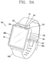
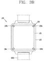
- FIGS. 3A and 3B are a perspective view and a rear view of a mobile terminal 100 shown in FIG. 2 , respectively.
- FIG. 4 is a perspective view of a mounting device 200 shown in FIG. 2 .
- the watch-type mobile terminal system 10 includes a mobile terminal 100, and a mounting device 200 configured to mount the mobile terminal 100.
- the watch-type mobile terminal 100 includes a terminal body 100a having a display unit 151, and a band 100b connected to the terminal body 100a and configured to be wearable on a user's wrist.
- the terminal body 100a includes cases 101 and 102 forming appearance of the terminal body 100a.
- the cases 101 and 102 may include a first case 101 and a second case 102 each having an inner space for accommodating various types of electronic components.
- the first case 101 is mounted to cover a rear side opening of the second case 102
- a window 151 a is mounted to a front side opening of the second case 102.
- the watch-type mobile terminal 100 is configured to perform wireless communication, and an antenna for such wireless communication may be installed at the terminal body 100a.
- the antenna may extend its function using the cases 101 and 102.
- the cases 101 and 102 including a conductive material may be configured to extend a ground region or a radiation region by being electrically connected to the antenna.
- the display unit 151 may be disposed on a front surface of the terminal body 100a to output information.
- a touch sensor may be provided at the display unit 151 to thus be implemented as a touch screen.
- the window 151 a of the display unit 151 may be mounted to the second case 102, thereby forming a front surface of the terminal body together with the first case 101.
- the audio output unit 152, the camera 121, the microphone 122, the user input unit 123, etc. may be provided at the terminal body 100a.
- the display unit 151 may serve as the user input unit 123. In this case, no additional key may be provided at the terminal body 100a.
- the band 100b wearable on a wrist in an enclosing manner, may be formed of a flexible material.
- the band 100b may be formed of leather, rubber, silicon, synthetic resin, etc.
- the band 100b may be detachably mounted to the terminal body 100a so that it can be replaced by any one of various types of bands according to a user's preference.
- the band 100b is connected to the second case 102.
- the band 100b may be used to extend a function of an antenna.
- a ground extension portion (not shown) configured to extend a ground region by being electrically connected to an antenna, may be mounted in the band 100b.
- the band 100b may be provided with a fastener 100c.
- the fastener 100c may be implemented as a buckle, a snap-fittable hook structure, a Velcro (trademark name), etc.
- the band 10b may include an elastic section, or may be formed of an elastic material. In the drawings, the fastener 100c is implemented in the form of a buckle.
- the mobile terminal 100 is configured to be mounted to the mounting device 200.
- the mobile terminal 100 may be configured to be mounted to the mounting device so as to receive charging power from the mounting device, or so as to perform data communication with an external device electrically connected to the mounting device 200.
- the mounting device 200 is provided with an accommodation portion 200a laid on a bottom surface or fixed to a wall surface, the accommodation portion 200a configured to accommodate therein at least part of the mobile terminal 100 so that the mobile terminal 100 can be mounted. As shown, the accommodation portion 200a may be formed to accommodate the terminal body 100a therein.
- An external device may be electrically connected to the mounting device 200 through a cable (C).
- a printed circuit board 220 (refer to FIG. 5 ) is disposed in the mounting device 200, and a contact pin 230 for electrical connection with the mobile terminal 100 is mounted to the PCB 220. At least part of the contact pin 230 protrudes from the accommodation portion 200a. Once the terminal body 100a is accommodated in the accommodation portion 200a, the contact pin 230 is made to contact a terminal (a coupling member 130 to be explained later) provided at the terminal body 100a.
- the mobile terminal 100 of the present invention is provided with a structure where a coupling structure between the first case 101 and the second case 102, and an electrical connection structure between the mobile terminal 100 and the mounting device 200 has been integrated with each other.
- a coupling structure between the first case 101 and the second case 102, and an electrical connection structure between the mobile terminal 100 and the mounting device 200 has been integrated with each other.
- FIG. 5 is a sectional view illustrating part 'A' shown in FIG. 2 , i.e., an electrical connection structure between the mobile terminal 100 and the mounting device 200.
- the first case 101 and the second case 102 are coupled to each other to form an inner space of the terminal body 100a.
- the first case 101 may be understood as a rear case disposed on the wrist
- the second case 102 may be understood as a front case exposed to outside.
- a printed circuit board 181 is disposed at the inner space.
- the PCB 181 may be mounted to the first case 101.
- the PCB 181 may be configured as an example of the controller 180 (refer to FIG. 1 ) for operating various functions of the watch-type mobile terminal 100, and various types of electronic components may be mounted to at least one surface of the PCB 181.
- a coupling member 130 is configured to couple the first case 101 and the second case 102 to each other.
- the coupling member 130 may be screw-coupled to the first case 101 and the second case 102.
- well-known screws may be generally used as the coupling member 130.
- the coupling member 130 penetrates the PCB 181 to be electrically connected to the PCB 181, That is, the coupling member 130 may be inserted into the first case 101, and may be coupled to the second case 102 by passing through the PCB 181. Under such coupling structure, an end portion of the coupling member 130, i.e., a head portion 132 is exposed to outside from the first case 101.
- the coupling member 130 is disposed at a position corresponding to the contact pin 230 so as to contact the contact pin 230 when the terminal body 100a is mounted to the mounting device 200.
- the coupling member 130 is formed of a conductive metallic material. Accordingly, when the terminal body 100a is mounted to the mounting device 200, the coupling member 130 contacts the contact pin 230 to thus electrically connect the PCB 181 and the mounting device 200 to each other. That is, the coupling member 130 performs not only its own function (coupling function between the first case 101 and the second case 102), but also an electrical connection function between the watch-type mobile terminal 100 and the mounting device 200.
- the mobile terminal For electrical connection between a mobile terminal and a mounting device, it is general for the mobile terminal to be provided with a terminal configured to contact a contact pin of the mounting device.
- the watch-type mobile terminal 100 requires no additional terminal because the coupling member 130 also performs such electrical connection function.
- appearance of the watch-type mobile terminal 100 can become more simple and sophisticated.
- the coupling member 130 may be provided at the watch-type mobile terminal 100 in at least one in number.
- FIG. 3B illustrates that coupling members 130a, 130b, 130c and 130d have been disposed at corners of the first case 101, respectively.
- the coupling member 130a, 130b, 130c and 130d may serve as terminals for performing different functions.
- the coupling members 130a, 130b, 130c and 130d may be disposed at corners of the first case 101 having a quadrangular shape, and may serve as VBUS, D-, D+ and GND terminals, respectively.
- the coupling members 130a, 130b, 130c and 130d are arranged in a spaced (distant) manner, a malfunction and a short-circuit, occurring from the conventional structure where terminals are arranged in a compact manner, can be prevented.
- the coupling member 130 and the contact pin 230 can be fabricated to have a larger size than the conventional ones. Accordingly, a charging current can be increased and thus the watch-type mobile terminal 100 can be charged more rapidly.
- a circuit portion 181b is formed on at least one surface of the PCB 181, and the circuit portion 181b is connected to the power supply unit 190, the memory 170, etc.
- connection portion 181 c may be configured in the form of a loop along an inner side wall of the through hole 181 a, so as to contact an outer circumferential surface of the coupling member 130 when the coupling member 130 is inserted into the through hole 181 a.
- the connection portion 181c may be integrally formed with the circuit portion 181b.
- the connection portion 181c contacting the coupling member 130 may be implemented as the circuit portion 181 b partially extends to be formed on an inner side wall of the through hole 181 a.
- a thread groove, corresponding to a screw thread of the coupling member 130, may be formed on an inner side wall of the through hole 181 a.
- the coupling member 130 may be coupled to the PCB 181 by screw-coupling, so that the PCB 181 can be fixed more firmly, and the coupling member 130 and the connection portion 181c can be connected to each other more stably.
- the watch-type mobile terminal system 10 may be provided with a structure for stable contact between the coupling member 130 and the contact pin 230.
- a structure for stable contact between the coupling member 130 and the contact pin 230 will be explained in more detail
- the mounting device 200 may be provided with a holding guide 210 protruding from a mounting device body 201 in correspondence to an outer appearance of the watch-type mobile terminal 100.
- the holding guide 210 may be formed to exclude part corresponding to the band 100b, so that the band 100b can be mounted to the holding guide 210 provided at two sides of the mounting device 200. Since the accommodation portion 200a for accommodating at least part of the watch-type mobile terminal 100 is defined by the holding guide 210, the watch-type mobile terminal 100 can be mounted to a precise position.
- the coupling member 130 may be arranged at each corner of the first case 101.
- the contact pin 230 may be arranged at each corner of the holding guide 210.
- a coupling hole 101a for inserting the coupling member 130 thereinto is formed at the first case 101.
- the coupling hole 101 a may include a first hole 101 a' communicated with outside, and a second hole 101 a" for inserting a body portion 131 of the coupling member 130 thereinto.
- the first hole 101 a' is formed to have a diameter larger than that of the second hole 101 a", and a mounting surface 101b for mounting a head portion 132 of the coupling member 130 is formed on a bottom surface of the first hole 101a'. That is, the head portion 132 is mounted to the mounting surface 101b, and is exposed to outside through the first hole 101 a'.
- the coupling member 130 may be inserted into the coupling hole with remaining a predetermined empty space (S) above the coupling member 130, such that the contact pin 230 is inserted into the empty space (S) when the watch-type mobile terminal 100 is mounted to the mounting device 200. That is, if the head portion 132 is mounted to the mounting surface 101 b as the coupling member 130 is completely coupled to the coupling hole, the empty space (S) is formed above the coupling member 130 with a depth.
- the depth corresponds to a value obtained by deducting a height of the head portion 132, from a depth of the first hole 101 a'.
- the contact pin 230 is inserted into the empty space (S) when the watch-type mobile terminal 100 is mounted to the mounting device 200. Then the contact pin 230 inserted into the empty space (S) comes in contact with the head portion 132 of the coupling member 130. Under such structure, stable contact between the coupling member 130 and the contact pin 230 can be maintained, even if the watch-type mobile terminal 100 is moved toward a side direction by an unintended external force.
- the contact pin 230 was illustrated conceptually.
- the contact pin 230 may be configured to protrude from the mounting device 200, or may be configured to be elastically transformable.
- FIG. 5 another example of the contact pin 230 shown in FIG. 5 will be explained in more detail with reference to FIGS. 6A and 6B .
- a contact pin 230' is formed to extend to one direction so that at least part thereof can protrude from the mounting device 200', and is formed to be compressible and tensile along an axial direction.
- the contact pin 230' includes a first pin 231', a second pin 232' and an elastic member 233'.
- the first pin 231' is mounted to a printed circuit board (PCB) 220', and is electrically connected to a circuit portion 220a'.
- the second pin 232' is disposed to accommodate therein at least part of the first pin 231', and is configured to be movable along an axial direction of the first pin 231'.
- the elastic member 233' is supported at an end portion of the first pin 231' and an inner side wall of the second pin 232', respectively, thereby enabling the second pin 232' to elastically behave along an axial direction of the first pin 231'.
- An end portion of the second pin 232' may be inserted into an accommodation groove 231 a' of the first pin 231', for prevention of separation of the second pin 232' due to a tensile force of the elastic member 233'.
- a contact pin 230" may be configured in the form of a clip mounted to a printed circuit board (PCB) 220", the clip elastically movable toward inside and outside of a mounting device 200" by being partially or wholly exposed to the mounting device 200".
- PCB printed circuit board
- the present invention is not limited to such contact pins 230, 230' and 230". That is, other type of known elastically-transformable contact pin can be also applied to the contact pin 230 of the present invention.
- the contact pins 230' and 230" are configured to be elastically-transformable, the contact pins 230' and 230" elastically press the coupling member 130.
- contact between the coupling member 130 and the contact pins 230' and 230" can be maintained more stably.
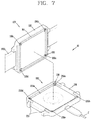
- FIG. 7 is a conceptual view illustrating a structure to prevent a mounted state in a reverse direction in a case where the watch-type mobile terminal of FIG. 2 is mounted to a mounting device.
- the coupling member 130 may include a first magnetic substance so that an attractive force can be applied between the coupling member 130 and a corresponding contact pin 230 formed of a metallic material. Under such structure, if the terminal body 100a is disposed close to the accommodation portion 200a, the terminal body 100a may be accommodated in the accommodation portion 200a as an attractive force is applied between the coupling member 130 and the contact pin 230. And the coupling member 130 and the contact pin 230 may contact each other more stably by a magnetic force.
- the watch-type mobile terminal 100 may be arranged on the mounting device 200 in a rotated state (180° in the drawing). If the coupling member 130 contacts the non-corresponding contact pin 230 in a state where the watch-type mobile terminal 100 has been arranged in a reverse direction, not in a forward direction, a malfunction of the watch-type mobile terminal 100 may occur or the watch-type mobile terminal 100 or the mounting device 200 may have a circuit defection.
- the contact pin 230 may include a second magnetic substance having a different polarity from the coupling member 130.
- the coupling member 130 may be formed to have the same polarity as a non-corresponding contact pin 230 rather than a corresponding contact pin 230, such that a repulsive force is applied when the coupling member 130 is close to the non-corresponding contact pin 230.
- the coupling member 130a is formed to have a positive (+) polarity, and the corresponding contact pin 230a is formed to have a negative (-) polarity. If the watch-type mobile terminal 100 is arranged on the mounting device 200 in a rotated state by 180°, the coupling member 130a is disposed to face a contact pin 230c having a positive (+) polarity. As a result, a repulsive force occurs between the coupling member 130a and the contact pin 230c. Accordingly, a mounted state of the watch-type mobile terminal 100 in a reverse direction can be prevented.
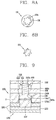
- FIGS. 8A and 8B are conceptual views illustrating an end portion of the coupling member 130 shown in FIG. 3B , and an end portion of the contact pin 230 shown in FIG. 4 , respectively.
- a recess portion 132a recessed in correspondence to at least part of the contact pin 230 so as to insert said at least part of the contact pin 230, may be formed at the head portion 132 of the coupling member 130 exposed to outside by being mounted to the mounting surface of the coupling hole 101a.
- the contact pin 230 may be formed to have the same shape as the recess portion 132a, or may be formed to have a shape corresponding to at least part of the recess portion 132a.
- the contact pin 230 As the contact pin 230 is inserted into the recess portion 132a of the coupling member 130, the contact pin 230 and the coupling member 130 can be fixedly-coupled to each other more stably.
- the shape of the contact pin 230 and the recess portion 132a is not limited to the illustrated one, but may be modified to various shapes.
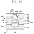
- FIGS. 9 and 10 are conceptual views illustrating another example of an electrical connection structure between a mobile terminal 1100 and a mounting device 1200 shown in FIG. 5 .
- connection member 1182 formed to be electrically connected to a circuit portion 1181b, is mounted to a printed circuit board (PCB) 1181.
- PCB printed circuit board
- the connection member 1182 is disposed between the PCB 1181 an a second case 1102, and is arranged to cover at least part of the circuit portion 1181b.
- connection member 1182 is provided with a hole 1182a corresponding to a through hole 1181a of the PCB 1181.
- a coupling member 1130 is coupled to the second case 1102, via a first case 1101, the PCB 1181 and the connection member 1182, sequentially.
- the coupling member 1130 comes in contact with the connection member 1182, thereby being electrically connected to the circuit portion 1181 b.
- connection member 1182 may be mounted to the PCB 1181, and may be screw-coupled to the coupling member 1130. Under such configuration, the coupling member 1130 and the PCB 1181 can stably contact each other, and the watch-type mobile terminal can be charged more rapidly due to increase of a charging current.
- a sealing member 2133 for sealing a coupling hole 2101 a may be disposed between a head portion 2132 of a coupling member 2130 and a mounting surface 2101b of the coupling hole 2101 a, the mounting surface where the head portion 2132 is mounted.
- the sealing member 2133 may prevent foreign materials such as dust or liquid from being introduced into a mobile terminal 2100 through the coupling hole 2101 a.
- the sealing member 2133 may be formed of an elastically-transformable material such as rubber and silicon.
- the coupling member 2130 is screw-coupled to a first case 2101 and a second case 2102.
- the sealing member 2133 may be configured to be elastically pressed by the head portion 2132 to thus be adhered to the mounting surface 2010b, when the coupling member 2130 is screw-coupled to the first case 2101 and the second case 2102.
- the aforementioned structure may be equally applied to mobile terminals 1100 and 2100 of FIGS. 9 and 10 unless it is logically contradictory.
- the structure for preventing a mounted state in a reverse direction which was explained in FIG. 7 , may be also applied to the mobile terminals 1100 and 2100 of FIGS. 9 and 10 .
- the structures aforementioned in FIGS. 9 and 10 may combine with each other.
- an electrical connection structure between a mobile terminal and a mounting device may be applicable not only to a watch-type mobile terminal, but also to various types such as a clip type, a glass type, a bar type, a folder type where two or more bodies are relative-movably coupled to each other, a flip type, a slide type, a swing type and a swivel type.
Landscapes
- Engineering & Computer Science (AREA)
- Computer Hardware Design (AREA)
- Theoretical Computer Science (AREA)
- Human Computer Interaction (AREA)
- Physics & Mathematics (AREA)
- General Engineering & Computer Science (AREA)
- General Physics & Mathematics (AREA)
- Telephone Set Structure (AREA)
- Electric Clocks (AREA)
- Coupling Device And Connection With Printed Circuit (AREA)
Claims (15)
- Mobiles Armbanduhr-Endgerät (100, 1100, 2100), das Folgendes umfasst:einen Endgerätekörper (100a), der ein erstes Gehäuse (101, 1101, 2101) und ein zweites Gehäuse (102, 1102, 2102) enthält, die miteinander verbunden sind, wobei das erste Gehäuse (101, 1101, 2101) und das zweite Gehäuse (102, 1102, 2102) einen Innenraum des Endgerätekörpers (100a) definieren, wobei der Endgerätekörper (100a) konfiguriert ist, an einer Aufnahmevorrichtung (200, 200', 200", 1200, 2200) befestigt werden zu können, die einen Kontaktstift (230, 230', 230", 1230, 2230) enthält;eine gedruckte Leiterplatte (181, 1181, 2181), die in dem Innenraum des Endgerätekörpers (100a) angeordnet ist; dadurch gekennzeichnet, dassein Kopplungselement (130, 1130, 2130) durch die gedruckte Leiterplatte (181, 1181, 2181) führt, wobei es das erste Gehäuse (101, 1101, 2101) und das zweite Gehäuse (102, 1102, 2102) miteinander verbindet, wobei das Kopplungselement (130, 1130, 2130) mit der gedruckten Leiterplatte (181, 1181, 2181) elektrisch verbunden ist und wobei das Kopplungselement (130, 1130, 2130) den Kontaktstift (230, 230' 230", 1230, 2230) kontaktiert, wenn der Endgerätekörper (100a) an der Aufnahmevorrichtung (200, 200', 200", 1200, 2200) befestigt wird, derart dass das Kopplungselement (130, 1130, 2130) und der Kontaktstift (230, 230', 230", 1230, 2230) die gedruckte Leiterplatte (181, 1181, 218) und die Aufnahmevorrichtung (200, 200', 200", 1200, 2200) elektrisch miteinander verbinden.
- Mobiles Armbanduhr-Endgerät (100, 1100, 2100) nach Anspruch 1, das ferner mehrere Kopplungselemente (130a, 130b, 130c, 130d) umfasst, wobei jedes der mehreren Kopplungselemente (130a, 130b, 130c, 130d) in einer entsprechenden Ecke des Endgerätekörpers (100a) angeordnet ist.
- Mobiles Armbanduhr-Endgerät (100, 1100, 2100) nach Anspruch 2, wobei die Aufnahmevorrichtung (200, 200', 200", 1200, 2200) mehrere Kontaktstifte (230a, 230b, 230c, 230d) umfasst, von denen jeder aus einem magnetischen Material ausgebildet ist, wobei jeder der mehreren Kontaktstifte (230a, 230b, 230c, 230d) einem der mehreren Kopplungselemente (130a, 130b, 130c, 130d) entspricht und wobei jedes der mehreren Kopplungselemente (130a, 130b, 130c, 130d) ein magnetisches Material enthält, wobei die magnetische Polarität zwischen jedem Kopplungselement (130, 1130, 2130) und seinem entsprechenden Kontaktstift (230, 230', 230", 1230, 2230) verschieden ist, derart dass ein anziehende Kraft zwischen jedem Kopplungselement (130, 1130, 2130) und seinem entsprechenden Kontaktstift (230, 230', 230", 1230, 2230) angewendet wird, und wobei die magnetische Polarität zwischen jedem Kopplungselement (130, 1130, 2130) und einem nicht entsprechenden Kontaktstift (230, 230', 230", 1230, 2230) dieselbe ist, derart dass eine abstoßende Kraft zwischen jedem Kopplungselement (130, 1130, 2130) und dem nicht entsprechenden Kontaktstift (230, 230', 230", 1230, 2230) angewendet wird.
- Mobiles Armbanduhr-Endgerät (100, 1100, 2100) nach einem der Ansprüche 1 bis 3, wobei das erste Gehäuse (101, 1101, 2101) ein Verbindungsloch (101a, 1101a, 2101a) aufweist, das dort hindurch ausgebildet ist, und wobei ein erster Abschnitt (131, 1131, 2131) des Kopplungselements (130, 1130, 2130) durch das Verbindungsloch (101a, 1101a, 2101a) führt und ein verbleibender Kopfabschnitt (132, 1132, 2132) des Kopplungselements (130, 1130, 2130) den Kontaktstift (230, 230', 230", 1230, 2230) kontaktiert, wenn der Endgerätekörper (100a) an der Aufnahmevorrichtung (200, 200', 200", 1200, 2200) befestigt wird.
- Mobiles Armbanduhr-Endgerät (2100) nach Anspruch 4, das ferner ein Versiegelungselement (2133) umfasst, das zwischen dem Kopfabschnitt (2132) des Kopplungselements (2130) und einer Befestigungsfläche (2101b) des Verbindungslochs (2101a) angeordnet ist, wobei das Versiegelungselement (2133) konfiguriert ist, das Verbindungsloch (2101a) zu versiegeln.
- Mobiles Armbanduhr-Endgerät (2100) nach Anspruch 5, wobei der erste Abschnitt (2131) des Kopplungselements (2130) Gewinde umfasst und das erste und das zweite Gehäuse (2101, 2102) durch das Kopplungselement (2130) schraubverbunden werden und wobei das Versiegelungselement (2133) elastisch komprimiert wird, um das Verbindungsloch (2101a) zu versiegeln.
- Mobiles Armbanduhr-Endgerät (100, 1100, 2100) nach einem der Ansprüche 4 bis 6, wobei der Kopfabschnitt (132, 1132, 2132) des Kopplungselements (130, 1130, 2130) eine darin ausgebildete Vertiefung (132a) aufweist, wobei die Vertiefung (132a) konfiguriert ist, einen vorstehenden Abschnitt des Kontaktstifts (230, 230', 230", 1230, 2230) aufzunehmen, wenn der Endgerätekörper (100a) und die Aufnahmevorrichtung (200, 200', 200", 1200, 2200) miteinander verbunden werden.
- Mobiles Armbanduhr-Endgerät (100, 2100) nach einem der Ansprüche 1 bis 7, wobei die gedruckte Leiterplatte (181, 2181) ein Loch (181a, 2181a) aufweist, das dort hindurch ausgebildet ist, und ein erster Abschnitt (131, 2131) des Kopplungselements (130, 2130) durch das Loch (181a, 2181a) in der gedruckten Leiterplatte (181, 2181) führt und wobei die gedruckte Leiterplatte (181, 2181) eine Innenseitenwand umfasst, die aus einem elektrisch leitfähigen Material hergestellt ist, wobei die Innenseitenwand zumindest teilweise um das Loch (181a, 2181a) in der gedruckten Leiterplatte (181, 2181) ausgebildet ist und eine elektrische Verbindung zwischen dem Kopplungselement (130, 2130) und einem Schaltungsabschnitt (181b, 2181b) der gedruckten Leiterplatte (181, 2181) bereitstellt.
- Mobiles Armbanduhr-Endgerät (100, 2100) nach Anspruch 8, wobei die gedruckte Leiterplatte (181, 2181) einen Anschlussabschnitt (181c, 2181c) umfasst, der die Innenseitenwand mit dem Schaltungsabschnitt (181b, 2181b) der gedruckten Leiterplatte (181, 2181) verbindet.
- Mobiles Armbanduhr-Endgerät (1100) nach einem der Ansprüche 1 bis 7, das ferner ein Verbindungselement (1182) umfasst, das auf der gedruckten Leiterplatte (1181) befestigt ist, wobei das Verbindungselement (1182) mit einem Schaltungsabschnitt (1181b) der gedruckten Leiterplatte (1181) elektrisch verbunden ist, wobei das Verbindungselement (1182) ein Loch (1182a) aufweist, das dort hindurch ausgebildet ist, und wobei die gedruckte Leiterplatte (1181) ein Loch (1181a) aufweist, das dort hindurch ausgebildet ist, wobei das Loch (1182a) durch das Verbindungselement und das Loch (1181a) durch die gedruckte Leiterplatte (1181) derart miteinander ausgerichtet sind, dass ein Abschnitt des Kopplungselements (1130) durch das Loch (1181a) der gedruckten Leiterplatte (1181) und durch das Loch (1182a) des Verbindungselements (1182) führt.
- Mobiles Armbanduhr-Endgerät (1100), nach Anspruch 10, wobei das Verbindungselement (1182) auf der gedruckten Leiterplatte (1181) befestigt ist und wobei das Verbindungselement (1182) und das Kopplungselement (1130) Gewinde aufweisen, derart dass das Verbindungselement (1182) und das Kopplungselement (1130) schraubverbunden werden.
- Mobiles Armbanduhr-Endgerät (100, 1100, 2100) nach einem der Ansprüche 1 bis 11, wobei das Kopplungselement (130, 1130, 2130) eine magnetische Substanz enthält, derart dass zwischen dem Kopplungselement (130, 1130, 2130) und dem Kontaktstift (230, 230', 230", 1230, 2230), der aus einem metallischen Material ausgebildet ist, eine anziehende Kraft angewendet wird.
- System (10) mit einem mobilen Armbanduhr-Endgerät, das Folgendes umfasst:ein mobiles Armbanduhr-Endgerät (100, 1100, 2100) nach einem der Ansprüche 1 bis 12; undeine Aufnahmevorrichtung (200, 200', 200", 1200, 2200), die einen Kontaktstift (230, 230', 230", 1230, 2230) aufweist, wobei das mobile Armbanduhr-Endgerät (100, 1100, 2100) und die Aufnahmevorrichtung (200, 200', 200", 1200, 2200) derart konfiguriert sind, dass das mobile Armbanduhr-Endgerät (100, 1100, 2100) auf der Aufnahmevorrichtung (200, 200', 200", 1200, 2200) befestigt werden kann.
- System (10) mit einem mobilen Armbanduhr-Endgerät nach Anspruch 13, wobei die Aufnahmevorrichtung (200, 200', 200", 1200, 2200) ferner einen Aufnahmevorrichtungskörper (201, 1201, 2201) und eine Halteführung (210), die von dem Aufnahmevorrichtungskörper (201, 1201, 2201) vorsteht, enthält, wobei die Konfiguration der Halteführung (210) mit einer Außenabmessung des mobilen Armbanduhr-Endgeräts (100, 1100, 2100) übereinstimmt, wobei die Halteführung (210) konfiguriert ist, das Befestigen des mobilen Armbanduhr-Endgeräts (100, 1100, 2100) auf der Aufnahmevorrichtung (200, 200', 200", 1200, 2200) zu erleichtern, und wobei die Aufnahmevorrichtung (200, 200', 200", 1200, 2200) mehrere Kontaktstifte (230a, 230b, 230c, 230d) umfasst und wobei jeder der mehreren Kontaktstifte (230a, 230b, 230c, 230d) in einer entsprechenden Ecke angeordnet ist, die durch die Halteführung (210) gebildet wird.
- System (10) mit einem mobilen Armbanduhr-Endgerät nach Anspruch 13 oder 14, wobei der Kontaktstift (230') komprimierbar und in einer axialen Richtung spannbar ist und wobei der Kontaktstift (230') elastisch gegen das Kopplungselement (130, 1130, 2130) drückt.
Applications Claiming Priority (1)
| Application Number | Priority Date | Filing Date | Title |
|---|---|---|---|
| KR1020140059898A KR20150133053A (ko) | 2014-05-19 | 2014-05-19 | 와치 타입의 이동 단말기 및 이를 구비하는 이동 단말 시스템 |
Publications (3)
| Publication Number | Publication Date |
|---|---|
| EP2947539A2 EP2947539A2 (de) | 2015-11-25 |
| EP2947539A3 EP2947539A3 (de) | 2015-12-09 |
| EP2947539B1 true EP2947539B1 (de) | 2016-08-17 |
Family
ID=52292774
Family Applications (1)
| Application Number | Title | Priority Date | Filing Date |
|---|---|---|---|
| EP15150301.8A Not-in-force EP2947539B1 (de) | 2014-05-19 | 2015-01-07 | Mobiles Endgerät vom Uhrentyp und mobiles Endgerätesystem damit |
Country Status (4)
| Country | Link |
|---|---|
| US (1) | US9483074B2 (de) |
| EP (1) | EP2947539B1 (de) |
| KR (1) | KR20150133053A (de) |
| CN (1) | CN105100305B (de) |
Families Citing this family (6)
| Publication number | Priority date | Publication date | Assignee | Title |
|---|---|---|---|---|
| USD811387S1 (en) * | 2014-12-17 | 2018-02-27 | Sony Mobile Communications Inc. | Wrist-worn communication device |
| KR20160139733A (ko) * | 2015-05-28 | 2016-12-07 | 엘지전자 주식회사 | 이동 단말기 |
| CN105514574B (zh) * | 2015-12-30 | 2019-08-27 | 联想(北京)有限公司 | 便携式电子设备及其制造方法 |
| USD781853S1 (en) * | 2016-03-07 | 2017-03-21 | Apple Inc. | Wearable device |
| US10566715B2 (en) * | 2017-09-29 | 2020-02-18 | Apple Inc. | Reduced net force electrical connectors |
| KR102130831B1 (ko) * | 2017-10-11 | 2020-07-06 | 모비케이 주식회사 | 의료용 또는 미용 성분을 피부에 주입하기 위한 이온도입 장치 |
Family Cites Families (11)
| Publication number | Priority date | Publication date | Assignee | Title |
|---|---|---|---|---|
| JP2001177889A (ja) * | 1999-12-21 | 2001-06-29 | Casio Comput Co Ltd | 身体装着型音楽再生装置、及び音楽再生システム |
| JP2001186584A (ja) * | 1999-12-27 | 2001-07-06 | Casio Comput Co Ltd | 外部接続用アダプタおよび電子機器 |
| US7006408B2 (en) * | 2002-10-18 | 2006-02-28 | Zhuhai Xonix Electronic Watch Company Limited | Wristwatch capable of storing and transmitting data |
| CN100481630C (zh) * | 2003-02-21 | 2009-04-22 | Eta瑞士钟表制造股份有限公司 | 用于在便携式电子仪器和外部设备之间建立电连接、尤其用于对所述仪器的电池进行再充电的装置 |
| JP4945337B2 (ja) * | 2007-06-19 | 2012-06-06 | 株式会社東芝 | 電子機器 |
| BRPI0804769A2 (pt) * | 2007-11-05 | 2009-06-13 | Lg Electronics Inc | terminal móvel |
| KR101587092B1 (ko) * | 2008-11-04 | 2016-01-20 | 엘지전자 주식회사 | 이동 단말기 |
| KR101587138B1 (ko) * | 2009-08-27 | 2016-02-02 | 엘지전자 주식회사 | 이동 단말기 |
| KR101084651B1 (ko) * | 2010-03-05 | 2011-11-17 | 엘지전자 주식회사 | 확장 모듈 및 이를 구비한 휴대 전자기기 |
| KR20130032195A (ko) * | 2011-09-22 | 2013-04-01 | 엘지전자 주식회사 | 휴대 전자기기 |
| US9591913B2 (en) * | 2013-11-15 | 2017-03-14 | Jwin Electronics Corp. | Protection case |
-
2014
- 2014-05-19 KR KR1020140059898A patent/KR20150133053A/ko not_active Abandoned
-
2015
- 2015-01-07 EP EP15150301.8A patent/EP2947539B1/de not_active Not-in-force
- 2015-01-08 US US14/592,491 patent/US9483074B2/en not_active Expired - Fee Related
- 2015-01-23 CN CN201510036988.1A patent/CN105100305B/zh not_active Expired - Fee Related
Also Published As
| Publication number | Publication date |
|---|---|
| EP2947539A2 (de) | 2015-11-25 |
| US9483074B2 (en) | 2016-11-01 |
| CN105100305A (zh) | 2015-11-25 |
| EP2947539A3 (de) | 2015-12-09 |
| US20150331446A1 (en) | 2015-11-19 |
| CN105100305B (zh) | 2018-06-12 |
| KR20150133053A (ko) | 2015-11-27 |
Similar Documents
| Publication | Publication Date | Title |
|---|---|---|
| CN110312021B (zh) | 移动终端 | |
| US9665068B2 (en) | Smart bracelet | |
| US9612623B2 (en) | Mobile terminal | |
| US9979426B2 (en) | Watch-type mobile terminal including antenna | |
| KR102451371B1 (ko) | 와치타입 이동 단말기 및 무선충전장치 | |
| US10728371B2 (en) | Mobile terminal | |
| US9483074B2 (en) | Watch type mobile terminal and mobile terminal system having the same | |
| KR101587138B1 (ko) | 이동 단말기 | |
| EP3255967A1 (de) | Mobiles endgerät | |
| US10468816B2 (en) | Connector waterproof housing and mobile terminal | |
| KR101637368B1 (ko) | 와치타입 이동 단말기 | |
| KR20160122514A (ko) | 이동 단말기 | |
| EP3343884A1 (de) | Mobiles endgerät | |
| US20170212628A1 (en) | Mobile terminal | |
| KR20160012436A (ko) | 웨어러블 기기 | |
| US9813098B2 (en) | Mobile terminal | |
| US9894191B2 (en) | Mobile terminal | |
| KR20160100732A (ko) | 전자기기 | |
| KR20150080705A (ko) | 와치타입 이동 단말기 | |
| KR101587178B1 (ko) | 이동 단말기 | |
| KR20150144092A (ko) | 이동 단말기 | |
| KR101578013B1 (ko) | 이동 단말기 | |
| KR20160047739A (ko) | 리어 케이스 및 이를 포함하는 이동단말기 | |
| KR20170124750A (ko) | 접속부재 및 이동 단말기 | |
| KR20160034575A (ko) | 이동 단말기 |
Legal Events
| Date | Code | Title | Description |
|---|---|---|---|
| PUAL | Search report despatched |
Free format text: ORIGINAL CODE: 0009013 |
|
| PUAI | Public reference made under article 153(3) epc to a published international application that has entered the european phase |
Free format text: ORIGINAL CODE: 0009012 |
|
| AK | Designated contracting states |
Kind code of ref document: A2 Designated state(s): AL AT BE BG CH CY CZ DE DK EE ES FI FR GB GR HR HU IE IS IT LI LT LU LV MC MK MT NL NO PL PT RO RS SE SI SK SM TR |
|
| AX | Request for extension of the european patent |
Extension state: BA ME |
|
| AK | Designated contracting states |
Kind code of ref document: A3 Designated state(s): AL AT BE BG CH CY CZ DE DK EE ES FI FR GB GR HR HU IE IS IT LI LT LU LV MC MK MT NL NO PL PT RO RS SE SI SK SM TR |
|
| AX | Request for extension of the european patent |
Extension state: BA ME |
|
| RIC1 | Information provided on ipc code assigned before grant |
Ipc: G06F 1/16 20060101AFI20151102BHEP |
|
| 17P | Request for examination filed |
Effective date: 20160113 |
|
| RBV | Designated contracting states (corrected) |
Designated state(s): AL AT BE BG CH CY CZ DE DK EE ES FI FR GB GR HR HU IE IS IT LI LT LU LV MC MK MT NL NO PL PT RO RS SE SI SK SM TR |
|
| GRAP | Despatch of communication of intention to grant a patent |
Free format text: ORIGINAL CODE: EPIDOSNIGR1 |
|
| INTG | Intention to grant announced |
Effective date: 20160302 |
|
| RAP1 | Party data changed (applicant data changed or rights of an application transferred) |
Owner name: LG ELECTRONICS INC. |
|
| GRAS | Grant fee paid |
Free format text: ORIGINAL CODE: EPIDOSNIGR3 |
|
| GRAA | (expected) grant |
Free format text: ORIGINAL CODE: 0009210 |
|
| AK | Designated contracting states |
Kind code of ref document: B1 Designated state(s): AL AT BE BG CH CY CZ DE DK EE ES FI FR GB GR HR HU IE IS IT LI LT LU LV MC MK MT NL NO PL PT RO RS SE SI SK SM TR |
|
| REG | Reference to a national code |
Ref country code: GB Ref legal event code: FG4D |
|
| REG | Reference to a national code |
Ref country code: CH Ref legal event code: EP |
|
| REG | Reference to a national code |
Ref country code: IE Ref legal event code: FG4D |
|
| REG | Reference to a national code |
Ref country code: AT Ref legal event code: REF Ref document number: 821651 Country of ref document: AT Kind code of ref document: T Effective date: 20160915 |
|
| REG | Reference to a national code |
Ref country code: DE Ref legal event code: R096 Ref document number: 602015000181 Country of ref document: DE |
|
| REG | Reference to a national code |
Ref country code: FR Ref legal event code: PLFP Year of fee payment: 3 |
|
| REG | Reference to a national code |
Ref country code: NL Ref legal event code: MP Effective date: 20160817 |
|
| REG | Reference to a national code |
Ref country code: LT Ref legal event code: MG4D |
|
| REG | Reference to a national code |
Ref country code: AT Ref legal event code: MK05 Ref document number: 821651 Country of ref document: AT Kind code of ref document: T Effective date: 20160817 |
|
| PG25 | Lapsed in a contracting state [announced via postgrant information from national office to epo] |
Ref country code: IT Free format text: LAPSE BECAUSE OF FAILURE TO SUBMIT A TRANSLATION OF THE DESCRIPTION OR TO PAY THE FEE WITHIN THE PRESCRIBED TIME-LIMIT Effective date: 20160817 Ref country code: LT Free format text: LAPSE BECAUSE OF FAILURE TO SUBMIT A TRANSLATION OF THE DESCRIPTION OR TO PAY THE FEE WITHIN THE PRESCRIBED TIME-LIMIT Effective date: 20160817 Ref country code: NO Free format text: LAPSE BECAUSE OF FAILURE TO SUBMIT A TRANSLATION OF THE DESCRIPTION OR TO PAY THE FEE WITHIN THE PRESCRIBED TIME-LIMIT Effective date: 20161117 Ref country code: HR Free format text: LAPSE BECAUSE OF FAILURE TO SUBMIT A TRANSLATION OF THE DESCRIPTION OR TO PAY THE FEE WITHIN THE PRESCRIBED TIME-LIMIT Effective date: 20160817 Ref country code: NL Free format text: LAPSE BECAUSE OF FAILURE TO SUBMIT A TRANSLATION OF THE DESCRIPTION OR TO PAY THE FEE WITHIN THE PRESCRIBED TIME-LIMIT Effective date: 20160817 Ref country code: FI Free format text: LAPSE BECAUSE OF FAILURE TO SUBMIT A TRANSLATION OF THE DESCRIPTION OR TO PAY THE FEE WITHIN THE PRESCRIBED TIME-LIMIT Effective date: 20160817 Ref country code: RS Free format text: LAPSE BECAUSE OF FAILURE TO SUBMIT A TRANSLATION OF THE DESCRIPTION OR TO PAY THE FEE WITHIN THE PRESCRIBED TIME-LIMIT Effective date: 20160817 |
|
| PG25 | Lapsed in a contracting state [announced via postgrant information from national office to epo] |
Ref country code: AT Free format text: LAPSE BECAUSE OF FAILURE TO SUBMIT A TRANSLATION OF THE DESCRIPTION OR TO PAY THE FEE WITHIN THE PRESCRIBED TIME-LIMIT Effective date: 20160817 Ref country code: LV Free format text: LAPSE BECAUSE OF FAILURE TO SUBMIT A TRANSLATION OF THE DESCRIPTION OR TO PAY THE FEE WITHIN THE PRESCRIBED TIME-LIMIT Effective date: 20160817 Ref country code: ES Free format text: LAPSE BECAUSE OF FAILURE TO SUBMIT A TRANSLATION OF THE DESCRIPTION OR TO PAY THE FEE WITHIN THE PRESCRIBED TIME-LIMIT Effective date: 20160817 Ref country code: PT Free format text: LAPSE BECAUSE OF FAILURE TO SUBMIT A TRANSLATION OF THE DESCRIPTION OR TO PAY THE FEE WITHIN THE PRESCRIBED TIME-LIMIT Effective date: 20161219 Ref country code: SE Free format text: LAPSE BECAUSE OF FAILURE TO SUBMIT A TRANSLATION OF THE DESCRIPTION OR TO PAY THE FEE WITHIN THE PRESCRIBED TIME-LIMIT Effective date: 20160817 Ref country code: GR Free format text: LAPSE BECAUSE OF FAILURE TO SUBMIT A TRANSLATION OF THE DESCRIPTION OR TO PAY THE FEE WITHIN THE PRESCRIBED TIME-LIMIT Effective date: 20161118 Ref country code: PL Free format text: LAPSE BECAUSE OF FAILURE TO SUBMIT A TRANSLATION OF THE DESCRIPTION OR TO PAY THE FEE WITHIN THE PRESCRIBED TIME-LIMIT Effective date: 20160817 |
|
| PG25 | Lapsed in a contracting state [announced via postgrant information from national office to epo] |
Ref country code: EE Free format text: LAPSE BECAUSE OF FAILURE TO SUBMIT A TRANSLATION OF THE DESCRIPTION OR TO PAY THE FEE WITHIN THE PRESCRIBED TIME-LIMIT Effective date: 20160817 Ref country code: RO Free format text: LAPSE BECAUSE OF FAILURE TO SUBMIT A TRANSLATION OF THE DESCRIPTION OR TO PAY THE FEE WITHIN THE PRESCRIBED TIME-LIMIT Effective date: 20160817 |
|
| REG | Reference to a national code |
Ref country code: DE Ref legal event code: R097 Ref document number: 602015000181 Country of ref document: DE |
|
| PG25 | Lapsed in a contracting state [announced via postgrant information from national office to epo] |
Ref country code: CZ Free format text: LAPSE BECAUSE OF FAILURE TO SUBMIT A TRANSLATION OF THE DESCRIPTION OR TO PAY THE FEE WITHIN THE PRESCRIBED TIME-LIMIT Effective date: 20160817 Ref country code: SK Free format text: LAPSE BECAUSE OF FAILURE TO SUBMIT A TRANSLATION OF THE DESCRIPTION OR TO PAY THE FEE WITHIN THE PRESCRIBED TIME-LIMIT Effective date: 20160817 Ref country code: BG Free format text: LAPSE BECAUSE OF FAILURE TO SUBMIT A TRANSLATION OF THE DESCRIPTION OR TO PAY THE FEE WITHIN THE PRESCRIBED TIME-LIMIT Effective date: 20161117 Ref country code: SM Free format text: LAPSE BECAUSE OF FAILURE TO SUBMIT A TRANSLATION OF THE DESCRIPTION OR TO PAY THE FEE WITHIN THE PRESCRIBED TIME-LIMIT Effective date: 20160817 Ref country code: BE Free format text: LAPSE BECAUSE OF FAILURE TO SUBMIT A TRANSLATION OF THE DESCRIPTION OR TO PAY THE FEE WITHIN THE PRESCRIBED TIME-LIMIT Effective date: 20160817 Ref country code: DK Free format text: LAPSE BECAUSE OF FAILURE TO SUBMIT A TRANSLATION OF THE DESCRIPTION OR TO PAY THE FEE WITHIN THE PRESCRIBED TIME-LIMIT Effective date: 20160817 |
|
| PLBE | No opposition filed within time limit |
Free format text: ORIGINAL CODE: 0009261 |
|
| STAA | Information on the status of an ep patent application or granted ep patent |
Free format text: STATUS: NO OPPOSITION FILED WITHIN TIME LIMIT |
|
| 26N | No opposition filed |
Effective date: 20170518 |
|
| PG25 | Lapsed in a contracting state [announced via postgrant information from national office to epo] |
Ref country code: SI Free format text: LAPSE BECAUSE OF FAILURE TO SUBMIT A TRANSLATION OF THE DESCRIPTION OR TO PAY THE FEE WITHIN THE PRESCRIBED TIME-LIMIT Effective date: 20160817 |
|
| PG25 | Lapsed in a contracting state [announced via postgrant information from national office to epo] |
Ref country code: MC Free format text: LAPSE BECAUSE OF FAILURE TO SUBMIT A TRANSLATION OF THE DESCRIPTION OR TO PAY THE FEE WITHIN THE PRESCRIBED TIME-LIMIT Effective date: 20160817 |
|
| REG | Reference to a national code |
Ref country code: IE Ref legal event code: MM4A |
|
| PG25 | Lapsed in a contracting state [announced via postgrant information from national office to epo] |
Ref country code: LU Free format text: LAPSE BECAUSE OF NON-PAYMENT OF DUE FEES Effective date: 20170107 |
|
| REG | Reference to a national code |
Ref country code: FR Ref legal event code: PLFP Year of fee payment: 4 |
|
| PG25 | Lapsed in a contracting state [announced via postgrant information from national office to epo] |
Ref country code: IE Free format text: LAPSE BECAUSE OF NON-PAYMENT OF DUE FEES Effective date: 20170107 |
|
| REG | Reference to a national code |
Ref country code: CH Ref legal event code: PL |
|
| PG25 | Lapsed in a contracting state [announced via postgrant information from national office to epo] |
Ref country code: MT Free format text: LAPSE BECAUSE OF NON-PAYMENT OF DUE FEES Effective date: 20170107 |
|
| PG25 | Lapsed in a contracting state [announced via postgrant information from national office to epo] |
Ref country code: AL Free format text: LAPSE BECAUSE OF FAILURE TO SUBMIT A TRANSLATION OF THE DESCRIPTION OR TO PAY THE FEE WITHIN THE PRESCRIBED TIME-LIMIT Effective date: 20160817 |
|
| PG25 | Lapsed in a contracting state [announced via postgrant information from national office to epo] |
Ref country code: LI Free format text: LAPSE BECAUSE OF NON-PAYMENT OF DUE FEES Effective date: 20180131 Ref country code: CH Free format text: LAPSE BECAUSE OF NON-PAYMENT OF DUE FEES Effective date: 20180131 |
|
| PGFP | Annual fee paid to national office [announced via postgrant information from national office to epo] |
Ref country code: GB Payment date: 20181206 Year of fee payment: 5 Ref country code: FR Payment date: 20181207 Year of fee payment: 5 |
|
| PGFP | Annual fee paid to national office [announced via postgrant information from national office to epo] |
Ref country code: DE Payment date: 20181205 Year of fee payment: 5 |
|
| PG25 | Lapsed in a contracting state [announced via postgrant information from national office to epo] |
Ref country code: HU Free format text: LAPSE BECAUSE OF FAILURE TO SUBMIT A TRANSLATION OF THE DESCRIPTION OR TO PAY THE FEE WITHIN THE PRESCRIBED TIME-LIMIT; INVALID AB INITIO Effective date: 20150107 |
|
| PG25 | Lapsed in a contracting state [announced via postgrant information from national office to epo] |
Ref country code: CY Free format text: LAPSE BECAUSE OF FAILURE TO SUBMIT A TRANSLATION OF THE DESCRIPTION OR TO PAY THE FEE WITHIN THE PRESCRIBED TIME-LIMIT Effective date: 20160817 |
|
| PG25 | Lapsed in a contracting state [announced via postgrant information from national office to epo] |
Ref country code: MK Free format text: LAPSE BECAUSE OF FAILURE TO SUBMIT A TRANSLATION OF THE DESCRIPTION OR TO PAY THE FEE WITHIN THE PRESCRIBED TIME-LIMIT Effective date: 20160817 |
|
| PG25 | Lapsed in a contracting state [announced via postgrant information from national office to epo] |
Ref country code: TR Free format text: LAPSE BECAUSE OF FAILURE TO SUBMIT A TRANSLATION OF THE DESCRIPTION OR TO PAY THE FEE WITHIN THE PRESCRIBED TIME-LIMIT Effective date: 20160817 |
|
| PG25 | Lapsed in a contracting state [announced via postgrant information from national office to epo] |
Ref country code: IS Free format text: LAPSE BECAUSE OF FAILURE TO SUBMIT A TRANSLATION OF THE DESCRIPTION OR TO PAY THE FEE WITHIN THE PRESCRIBED TIME-LIMIT Effective date: 20161217 |
|
| REG | Reference to a national code |
Ref country code: DE Ref legal event code: R119 Ref document number: 602015000181 Country of ref document: DE |
|
| GBPC | Gb: european patent ceased through non-payment of renewal fee |
Effective date: 20200107 |
|
| PG25 | Lapsed in a contracting state [announced via postgrant information from national office to epo] |
Ref country code: GB Free format text: LAPSE BECAUSE OF NON-PAYMENT OF DUE FEES Effective date: 20200107 Ref country code: DE Free format text: LAPSE BECAUSE OF NON-PAYMENT OF DUE FEES Effective date: 20200801 Ref country code: FR Free format text: LAPSE BECAUSE OF NON-PAYMENT OF DUE FEES Effective date: 20200131 |