EP2947278A1 - Turboréacteur à engrenages avec générateur à grande vitesse - Google Patents
Turboréacteur à engrenages avec générateur à grande vitesse Download PDFInfo
- Publication number
- EP2947278A1 EP2947278A1 EP15167636.8A EP15167636A EP2947278A1 EP 2947278 A1 EP2947278 A1 EP 2947278A1 EP 15167636 A EP15167636 A EP 15167636A EP 2947278 A1 EP2947278 A1 EP 2947278A1
- Authority
- EP
- European Patent Office
- Prior art keywords
- generator
- rotor
- gas turbine
- set forth
- turbine engine
- Prior art date
- Legal status (The legal status is an assumption and is not a legal conclusion. Google has not performed a legal analysis and makes no representation as to the accuracy of the status listed.)
- Granted
Links
Images


Classifications
-
- F—MECHANICAL ENGINEERING; LIGHTING; HEATING; WEAPONS; BLASTING
- F01—MACHINES OR ENGINES IN GENERAL; ENGINE PLANTS IN GENERAL; STEAM ENGINES
- F01D—NON-POSITIVE DISPLACEMENT MACHINES OR ENGINES, e.g. STEAM TURBINES
- F01D15/00—Adaptations of machines or engines for special use; Combinations of engines with devices driven thereby
- F01D15/10—Adaptations for driving, or combinations with, electric generators
-
- F—MECHANICAL ENGINEERING; LIGHTING; HEATING; WEAPONS; BLASTING
- F01—MACHINES OR ENGINES IN GENERAL; ENGINE PLANTS IN GENERAL; STEAM ENGINES
- F01D—NON-POSITIVE DISPLACEMENT MACHINES OR ENGINES, e.g. STEAM TURBINES
- F01D25/00—Component parts, details, or accessories, not provided for in, or of interest apart from, other groups
- F01D25/02—De-icing means for engines having icing phenomena
-
- F—MECHANICAL ENGINEERING; LIGHTING; HEATING; WEAPONS; BLASTING
- F02—COMBUSTION ENGINES; HOT-GAS OR COMBUSTION-PRODUCT ENGINE PLANTS
- F02C—GAS-TURBINE PLANTS; AIR INTAKES FOR JET-PROPULSION PLANTS; CONTROLLING FUEL SUPPLY IN AIR-BREATHING JET-PROPULSION PLANTS
- F02C3/00—Gas-turbine plants characterised by the use of combustion products as the working fluid
- F02C3/04—Gas-turbine plants characterised by the use of combustion products as the working fluid having a turbine driving a compressor
- F02C3/107—Gas-turbine plants characterised by the use of combustion products as the working fluid having a turbine driving a compressor with two or more rotors connected by power transmission
-
- F—MECHANICAL ENGINEERING; LIGHTING; HEATING; WEAPONS; BLASTING
- F02—COMBUSTION ENGINES; HOT-GAS OR COMBUSTION-PRODUCT ENGINE PLANTS
- F02C—GAS-TURBINE PLANTS; AIR INTAKES FOR JET-PROPULSION PLANTS; CONTROLLING FUEL SUPPLY IN AIR-BREATHING JET-PROPULSION PLANTS
- F02C7/00—Features, components parts, details or accessories, not provided for in, or of interest apart form groups F02C1/00 - F02C6/00; Air intakes for jet-propulsion plants
- F02C7/32—Arrangement, mounting, or driving, of auxiliaries
-
- F—MECHANICAL ENGINEERING; LIGHTING; HEATING; WEAPONS; BLASTING
- F02—COMBUSTION ENGINES; HOT-GAS OR COMBUSTION-PRODUCT ENGINE PLANTS
- F02C—GAS-TURBINE PLANTS; AIR INTAKES FOR JET-PROPULSION PLANTS; CONTROLLING FUEL SUPPLY IN AIR-BREATHING JET-PROPULSION PLANTS
- F02C7/00—Features, components parts, details or accessories, not provided for in, or of interest apart form groups F02C1/00 - F02C6/00; Air intakes for jet-propulsion plants
- F02C7/36—Power transmission arrangements between the different shafts of the gas turbine plant, or between the gas-turbine plant and the power user
-
- F—MECHANICAL ENGINEERING; LIGHTING; HEATING; WEAPONS; BLASTING
- F02—COMBUSTION ENGINES; HOT-GAS OR COMBUSTION-PRODUCT ENGINE PLANTS
- F02K—JET-PROPULSION PLANTS
- F02K3/00—Plants including a gas turbine driving a compressor or a ducted fan
- F02K3/02—Plants including a gas turbine driving a compressor or a ducted fan in which part of the working fluid by-passes the turbine and combustion chamber
- F02K3/04—Plants including a gas turbine driving a compressor or a ducted fan in which part of the working fluid by-passes the turbine and combustion chamber the plant including ducted fans, i.e. fans with high volume, low pressure outputs, for augmenting the jet thrust, e.g. of double-flow type
- F02K3/06—Plants including a gas turbine driving a compressor or a ducted fan in which part of the working fluid by-passes the turbine and combustion chamber the plant including ducted fans, i.e. fans with high volume, low pressure outputs, for augmenting the jet thrust, e.g. of double-flow type with front fan
-
- F—MECHANICAL ENGINEERING; LIGHTING; HEATING; WEAPONS; BLASTING
- F05—INDEXING SCHEMES RELATING TO ENGINES OR PUMPS IN VARIOUS SUBCLASSES OF CLASSES F01-F04
- F05D—INDEXING SCHEME FOR ASPECTS RELATING TO NON-POSITIVE-DISPLACEMENT MACHINES OR ENGINES, GAS-TURBINES OR JET-PROPULSION PLANTS
- F05D2220/00—Application
- F05D2220/70—Application in combination with
- F05D2220/76—Application in combination with an electrical generator
-
- F—MECHANICAL ENGINEERING; LIGHTING; HEATING; WEAPONS; BLASTING
- F05—INDEXING SCHEMES RELATING TO ENGINES OR PUMPS IN VARIOUS SUBCLASSES OF CLASSES F01-F04
- F05D—INDEXING SCHEME FOR ASPECTS RELATING TO NON-POSITIVE-DISPLACEMENT MACHINES OR ENGINES, GAS-TURBINES OR JET-PROPULSION PLANTS
- F05D2230/00—Manufacture
- F05D2230/72—Maintenance
-
- F—MECHANICAL ENGINEERING; LIGHTING; HEATING; WEAPONS; BLASTING
- F05—INDEXING SCHEMES RELATING TO ENGINES OR PUMPS IN VARIOUS SUBCLASSES OF CLASSES F01-F04
- F05D—INDEXING SCHEME FOR ASPECTS RELATING TO NON-POSITIVE-DISPLACEMENT MACHINES OR ENGINES, GAS-TURBINES OR JET-PROPULSION PLANTS
- F05D2260/00—Function
- F05D2260/40—Transmission of power
- F05D2260/403—Transmission of power through the shape of the drive components
- F05D2260/4031—Transmission of power through the shape of the drive components as in toothed gearing
- F05D2260/40311—Transmission of power through the shape of the drive components as in toothed gearing of the epicyclical, planetary or differential type
-
- F—MECHANICAL ENGINEERING; LIGHTING; HEATING; WEAPONS; BLASTING
- F05—INDEXING SCHEMES RELATING TO ENGINES OR PUMPS IN VARIOUS SUBCLASSES OF CLASSES F01-F04
- F05D—INDEXING SCHEME FOR ASPECTS RELATING TO NON-POSITIVE-DISPLACEMENT MACHINES OR ENGINES, GAS-TURBINES OR JET-PROPULSION PLANTS
- F05D2260/00—Function
- F05D2260/60—Fluid transfer
-
- Y—GENERAL TAGGING OF NEW TECHNOLOGICAL DEVELOPMENTS; GENERAL TAGGING OF CROSS-SECTIONAL TECHNOLOGIES SPANNING OVER SEVERAL SECTIONS OF THE IPC; TECHNICAL SUBJECTS COVERED BY FORMER USPC CROSS-REFERENCE ART COLLECTIONS [XRACs] AND DIGESTS
- Y02—TECHNOLOGIES OR APPLICATIONS FOR MITIGATION OR ADAPTATION AGAINST CLIMATE CHANGE
- Y02T—CLIMATE CHANGE MITIGATION TECHNOLOGIES RELATED TO TRANSPORTATION
- Y02T50/00—Aeronautics or air transport
- Y02T50/60—Efficient propulsion technologies, e.g. for aircraft
Definitions
- This application relates to a geared turbofan with a generator driven with a low pressure compressor.
- Gas turbine engines are known and, typically, include a fan delivering air into a bypass duct as propulsion air, and further delivering air into a core engine. Air entering the core passes into a compressor section where it is compressed and delivered into a combustor. The air is mixed with fuel in the combustor and ignited. Products of this combustion pass downstream over turbine rotors driving them to rotate.
- the low speed spool drove a first stage compressor along with the fan rotor.
- the speed of rotation of the fan was limited by various considerations and, thus, in this direct drive engine, the speed of the entire low speed spool had to be limited.
- Generators are associated with gas turbine engines to generate electricity from the rotation of the spools. Generators may be associated with a high speed spool. It has also been proposed to utilize a generator driven by the low speed spool. However, since the speed of the low speed spool has been limited, the amount of power available from the generator driven by the low speed spool as a function of size and weight has been similarly limited.
- a gas turbine engine comprises a fan rotor, a lower speed compressor rotor and a higher speed compressor rotor, and a lower speed turbine rotor and a higher speed turbine rotor.
- the lower speed turbine rotor rotates the lower speed compressor rotor, and rotates a gear reduction to, in turn, rotate the fan rotor.
- the higher speed turbine rotor rotates the higher speed compressor rotor.
- a generator is driven to rotate with one of the lower speed turbine rotor and the fan rotor.
- the generator is mounted in an exhaust nozzle.
- the generator is mounted in a bearing compartment associated with the gear reduction.
- the generator is located in a nose cone.
- the generator is located in the nose cone forward of the fan rotor.
- a power supply outlet from the generator passes through static structure included in the gear reduction.
- the static structure includes journal pins, mounting intermediate gears in the reduction.
- the low pressure turbine drives a sun gear in the gear reduction through a flexible input shaft.
- the generator is driven to rotate with the lower speed turbine rotor.
- a generator rotor is rotated by a generator shaft driven by the flexible input shaft.
- the generator shaft is driven separately from the sun gear.
- heat generated by the generator provides an anti-icing feature for the nose cone.
- a power supply outlet from the generator passes through static structure included in the gear reduction.
- the static structure includes journal pins, mounting intermediate gears in the reduction.
- the nose cone is removable to provide access to the generator.
- the low pressure turbine drives a sun gear in the gear reduction through a flexible input shaft.
- heat generated by the generator provides an anti-icing feature for the nose cone.
- the generator is driven to rotate with the fan rotor.
- the generator is positioned forwardly of the fan rotor.
- heat generated by the generator provides an anti-icing feature for the nose cone.
- FIG. 1 schematically illustrates a gas turbine engine 20.
- the gas turbine engine 20 is disclosed herein as a two-spool turbofan that generally incorporates a fan section 22, a compressor section 24, a combustor section 26 and a turbine section 28.
- Alternative engines might include an augmentor section (not shown) among other systems or features.
- the fan section 22 drives air along a bypass flow path B in a bypass duct defined within a nacelle 15, while the compressor section 24 drives air along a core flow path C for compression and communication into the combustor section 26 then expansion through the turbine section 28.
- the exemplary engine 20 generally includes a low speed spool 30 and a high speed spool 32 mounted for rotation about an engine central longitudinal axis A relative to an engine static structure 36 via several bearing systems 38. It should be understood that various bearing systems 38 at various locations may alternatively or additionally be provided, and the location of bearing systems 38 may be varied as appropriate to the application.
- the low speed spool 30 generally includes an inner shaft 40 that interconnects a fan 42, a first (or low) pressure compressor 44 and a first (or low) pressure turbine 46.
- the inner shaft 40 is connected to the fan 42 through a speed change mechanism, which in exemplary gas turbine engine 20 is illustrated as a geared architecture 48 to drive the fan 42 at a lower speed than the low speed spool 30.
- the high speed spool 32 includes an outer shaft 50 that interconnects a second (or high) pressure compressor 52 and a second (or high) pressure turbine 54.
- a combustor 56 is arranged in exemplary gas turbine 20 between the high pressure compressor 52 and the high pressure turbine 54.
- a mid-turbine frame 57 of the engine static structure 36 is arranged generally between the high pressure turbine 54 and the low pressure turbine 46.
- the mid-turbine frame 57 further supports bearing systems 38 in the turbine section 28.
- the inner shaft 40 and the outer shaft 50 are concentric and rotate via bearing systems 38 about the engine central longitudinal axis A which is collinear with their longitudinal axes.
- the core airflow is compressed by the low pressure compressor 44 then the high pressure compressor 52, mixed and burned with fuel in the combustor 56, then expanded over the high pressure turbine 54 and low pressure turbine 46.
- the mid-turbine frame 57 includes airfoils 59 which are in the core airflow path C.
- the turbines 46, 54 rotationally drive the respective low speed spool 30 and high speed spool 32 in response to the expansion.
- gear system 48 may be located aft of combustor section 26 or even aft of turbine section 28, and fan section 22 may be positioned forward or aft of the location of gear system 48.
- the engine 20 in one example is a high-bypass geared aircraft engine.
- the engine 20 bypass ratio is greater than about six (6), with an example embodiment being greater than about ten (10)
- the geared architecture 48 is an epicyclic gear train, such as a planetary gear system or other gear system, with a gear reduction ratio of greater than about 2.3
- the low pressure turbine 46 has a pressure ratio that is greater than about five.
- the engine 20 bypass ratio is greater than about ten (10:1)
- the fan diameter is significantly larger than that of the low pressure compressor 44
- the low pressure turbine 46 has a pressure ratio that is greater than about five 5:1.
- Low pressure turbine 46 pressure ratio is pressure measured prior to inlet of low pressure turbine 46 as related to the pressure at the outlet of the low pressure turbine 46 prior to an exhaust nozzle.
- the geared architecture 48 may be an epicycle gear train, such as a planetary gear system or other gear system, with a gear reduction ratio of greater than about 2.3:1. It should be understood, however, that the above parameters are only exemplary of one embodiment of a geared architecture engine and that the present invention is applicable to other gas turbine engines including direct drive turbofans.
- the fan section 22 of the engine 20 is designed for a particular flight condition -- typically cruise at about 0.8 Mach and about 35,000 feet (10,668 meters).
- the flight condition of 0.8 Mach and 35,000 ft (10,668 meters), with the engine at its best fuel consumption - also known as "bucket cruise Thrust Specific Fuel Consumption ('TSFC')" - is the industry standard parameter of lbm of fuel being burned divided by lbf of thrust the engine produces at that minimum point.
- "Low fan pressure ratio” is the pressure ratio across the fan blade alone, without a Fan Exit Guide Vane (“FEGV”) system.
- the low fan pressure ratio as disclosed herein according to one non-limiting embodiment is less than about 1.45.
- Low corrected fan tip speed is the actual fan tip speed in ft/sec divided by an industry standard temperature correction of [(Tram °R) / (518.7 °R)] 0.5 .
- the "Low corrected fan tip speed” as disclosed herein according to one non-limiting embodiment is less than about 1150 ft / second (350.5 meters/second).
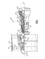
- An engine 80 which may operate generally as the engine 20 of Figure 1 , includes a nacelle 82.
- a fan rotor 85 drives blades 84 to deliver bypass air into a bypass duct and further delivers core air to a low pressure compressor 90.
- Low pressure compressor 90 rotates with a shaft 92 and is driven by a high speed low pressure turbine 94.
- a gear reduction 88 is driven along with the shaft 92 and, in turn, drives the fan rotor 85 at a slower speed.
- a nose cone 86 rotates with the fan rotor 85.
- a higher pressure compressor stage 96 is driven by a higher pressure turbine 98.
- a combustor 100 is positioned between compressor 96 and turbine 98.
- a generator 102 is shown mounted within the nose cone 86.
- a chamber (or compartment) 104 which will typically include bearings for mounting structure of the gear reduction 88, may receive a generator as an alternative location to be driven by the high-speed low pressure turbine prior to the speed reduction provided by the gear reduction 88.
- a nozzle 207 may receive a generator 106 which is driven to rotate with the turbine 94.
- the locations 102, 104 and 207 are also shown schematically in Figure 1 .
- FIG. 3 shows the generator 102 mounted in the nose cone 86.
- Fasteners 126 and 128 secure the nose cone 86 to rotate with a rotor 85 that rotates with fan blades 84.
- a hub 110 has a spline connection to be driven by the shaft 112 which is driven to rotate with a ring gear 109 in the gear reduction 88.
- a plurality of star gears 108 rotate about static journal pins 107. In other embodiments, the star gears 108 could be replaced by planet gears; generically, the two could be called intermediate gears.
- a sun gear 118 is driven to rotate through a spline connection with a flexible drive 120.
- the flexible drive 120 may further drive a shaft 111 through a spline connection to, in turn, drive a rotor portion 124 of the generator 102.
- a stator 113 is also included in the generator 102.
- a control 115 may control or condition the supplied electricity through one or more electrical conduits 116 extending through the journal pins 107, as an example.
- the wire extends to an output 117 , which may have an associated usage within the gas turbine engine or associated aircraft.
- Wire 116 provides a power supply outlet from the generator 102 that passes through static structure included in the gear reduction 88.
- the static structure includes journal pins 107 mounting intermediate gears 108 in the gear reduction 88.
- other static structure may be used.
- the location of the generators in the Figure 2 embodiment all provides the beneficial supply of greater amounts of power, as the shaft 92, turbine 94, and compressor 90, all rotate at a higher speed than in direct drive gas turbine engines.
- the speed supplied to the generator locations 102, 104 and 106 are all greater than with direct drive gas turbine engines.
- Advantages in generator design including power per unit volume and power per unit weight may be realized and may be attractive for use in aerospace systems.
- a nose cone 86 may accumulate ice during operation.
- the generation of the electricity at the generator 102 supplies heat for an anti-icing (de-icing, or preventing icing) of the nose cone and may further be sufficiently close to the fan rotor such that it helps all or a portion of the fan blades 84.
- the generator is also located forward of the fan rotor 84 to mount it more completely within the nose cone to improve this anti-icing. Moreover, this location optimizes the accessibility for maintenance, repair and servicing.
- the nose cone 86 is removable to provide access to the generator 102. As the generator rotor 124 will be rotating at a higher speed, a smaller volume, lighter weight generator may be utilized compared to the prior art generators driven by the slower rotating, low speed shaft.
- Locating the generator adjacent the fan rotor 85 may also allow use of an existing lubrication system to cool the generator.
- Figure 4 shows an alternative embodiment 299, wherein a shaft 300 is driven with the lower speed turbine, and drives a lower speed compressor rotor 302.
- the shaft also drives a gear reduction 304 to in turn drive a fan rotor 306.
- a nose cone 308 is positioned forwardly of the fan rotor 306, and receives a generator 309, which may be generally structured and mounted, and operate much like the generator of the Figure 3 embodiment, however, being driven at the lower speed of the fan rotor 306. While this embodiment will not gain the higher speed benefits as mentioned above, it will have other benefits, particularly when mounted in the nose cone 308.
Landscapes
- Engineering & Computer Science (AREA)
- Mechanical Engineering (AREA)
- General Engineering & Computer Science (AREA)
- Chemical & Material Sciences (AREA)
- Combustion & Propulsion (AREA)
- Retarders (AREA)
- Structures Of Non-Positive Displacement Pumps (AREA)
- Connection Of Motors, Electrical Generators, Mechanical Devices, And The Like (AREA)
Applications Claiming Priority (1)
| Application Number | Priority Date | Filing Date | Title |
|---|---|---|---|
| US201462000572P | 2014-05-20 | 2014-05-20 |
Publications (3)
| Publication Number | Publication Date |
|---|---|
| EP2947278A1 true EP2947278A1 (fr) | 2015-11-25 |
| EP2947278B1 EP2947278B1 (fr) | 2017-07-12 |
| EP2947278B2 EP2947278B2 (fr) | 2022-11-23 |
Family
ID=53264474
Family Applications (1)
| Application Number | Title | Priority Date | Filing Date |
|---|---|---|---|
| EP15167636.8A Active EP2947278B2 (fr) | 2014-05-20 | 2015-05-13 | Turboréacteur à engrenages avec générateur à grande vitesse |
Country Status (2)
| Country | Link |
|---|---|
| US (2) | US9915164B2 (fr) |
| EP (1) | EP2947278B2 (fr) |
Cited By (4)
| Publication number | Priority date | Publication date | Assignee | Title |
|---|---|---|---|---|
| WO2018038992A1 (fr) * | 2016-08-22 | 2018-03-01 | General Electric Company | Turbine à gaz à machine électrique intégrée |
| FR3090049A1 (fr) * | 2018-12-12 | 2020-06-19 | Safran Aircraft Engines | Turbomachine comportant un alternateur entre deux elements contrarotatifs |
| FR3131277A1 (fr) * | 2021-12-23 | 2023-06-30 | Safran Aircraft Engines | Système de calage et dégivrage de pales d’une helice d’un aeronef |
| FR3131272A1 (fr) * | 2021-12-23 | 2023-06-30 | Safran Aircraft Engines | Actionneur d’une piece montee mobile sur un support rotatif entraine par une turbomachine d’un aeronef |
Families Citing this family (12)
| Publication number | Priority date | Publication date | Assignee | Title |
|---|---|---|---|---|
| JP6511265B2 (ja) * | 2014-12-24 | 2019-05-15 | 川崎重工業株式会社 | 航空機用エンジン装置 |
| FR3054264B1 (fr) | 2016-07-25 | 2020-07-03 | Safran Aircraft Engines | Turbomachine a reducteur a train epicycloidal |
| GB201613029D0 (en) * | 2016-07-28 | 2016-09-14 | Rolls Royce Plc | A sun gear drive arrangement |
| RU2659426C1 (ru) * | 2017-02-01 | 2018-07-02 | Федеральное государственное унитарное предприятие "Центральный институт авиационного моторостроения им. П.И. Баранова" | Газотурбинная силовая установка летательного аппарата |
| US10738692B2 (en) | 2017-09-20 | 2020-08-11 | Honeywell International Inc. | Distributed propulsion and electric power generation system |
| US11008883B2 (en) * | 2017-09-20 | 2021-05-18 | General Electric Company | Turbomachine with a gearbox and integrated electric machine assembly |
| KR101965502B1 (ko) * | 2017-09-29 | 2019-04-03 | 두산중공업 주식회사 | 접속 어셈블리 및 이를 포함하는 가스터빈 |
| GB201720158D0 (en) * | 2017-12-04 | 2018-01-17 | Rolls Royce Plc | Gas turbine engine offtake |
| GB201804398D0 (en) * | 2018-03-20 | 2018-05-02 | Rolls Royce Plc | Gas turbine engine heatshield |
| GB201804397D0 (en) * | 2018-03-20 | 2018-05-02 | Rolls Royce Plc | Gas turbine engine heatshield |
| US11566567B2 (en) | 2018-12-10 | 2023-01-31 | Raytheon Technologies Corporation | Low pressure compressor control for a gas turbine engine |
| US11428160B2 (en) | 2020-12-31 | 2022-08-30 | General Electric Company | Gas turbine engine with interdigitated turbine and gear assembly |
Citations (5)
| Publication number | Priority date | Publication date | Assignee | Title |
|---|---|---|---|---|
| US20040255590A1 (en) * | 2003-06-23 | 2004-12-23 | Pratt & Whiney Canada Corp. | Differential geared turbine engine with torque modulation capability |
| US20080110151A1 (en) * | 2006-11-13 | 2008-05-15 | Welch Richard C | Turbofan emergency generator |
| EP2192291A2 (fr) * | 2008-11-28 | 2010-06-02 | Rolls-Royce plc | Ensemble démarreur-générateur d'un moteur d'avion |
| WO2010067172A2 (fr) * | 2008-12-12 | 2010-06-17 | Norbert Bayer | Appareil et procede de recuperation d'energie sur des aeronefs a reaction en approche d'atterrissage |
| DE102010049885A1 (de) * | 2010-11-01 | 2012-05-03 | Rolls-Royce Deutschland Ltd & Co Kg | Strahltriebwerk |
Family Cites Families (19)
| Publication number | Priority date | Publication date | Assignee | Title |
|---|---|---|---|---|
| GB628191A (en) * | 1947-02-06 | 1949-08-24 | C S A Ind Ltd | Improvements in or relating to de-icing means for spinners for aircraft screw propellers |
| US2827760A (en) * | 1951-04-18 | 1958-03-25 | Bristol Aero Engines Ltd | Combined anti-icing and generator cooling arrangement for a gas turbine engine |
| US3859785A (en) * | 1973-12-17 | 1975-01-14 | Curtiss Wright Corp | Turbine engine with integral compressor and alternator rotor |
| US4651521A (en) | 1985-11-21 | 1987-03-24 | Avco Corporation | Convertible turbo-fan, turbo-shaft aircraft propulsion system |
| GB9606546D0 (en) * | 1996-03-28 | 1996-06-05 | Rolls Royce Plc | Gas turbine engine system |
| DE19850052A1 (de) * | 1998-10-30 | 2000-05-04 | Asea Brown Boveri | Generator mit Doppelantrieb |
| US7642682B1 (en) * | 2006-05-26 | 2010-01-05 | Florida Turbine Technologies, Inc. | Integrated turbine and generator |
| US8585538B2 (en) * | 2006-07-05 | 2013-11-19 | United Technologies Corporation | Coupling system for a star gear train in a gas turbine engine |
| US9038362B2 (en) * | 2006-10-12 | 2015-05-26 | United Technologies Corporation | Turbofan engine with variable area fan nozzle and low spool generator for emergency power generation and method for providing emergency power |
| US7849668B2 (en) * | 2006-10-25 | 2010-12-14 | United Technologies Corporation | Rotor brake and windmilling lubrication system for geared turbofan engine |
| US20080310956A1 (en) * | 2007-06-13 | 2008-12-18 | Jain Ashok K | Variable geometry gas turbine engine nacelle assembly with nanoelectromechanical system |
| FR2919896B1 (fr) * | 2007-08-07 | 2009-10-30 | Snecma Sa | Turboreacteur comprenant un generateur de courant monte dans la soufflante et un procede de montage dudit generateur dans la soufflante |
| US8769924B2 (en) * | 2008-05-30 | 2014-07-08 | United Technologies Corporation | Gas turbine engine assembly including accessory components within the nacelle |
| US8375695B2 (en) * | 2009-06-30 | 2013-02-19 | General Electric Company | Aircraft gas turbine engine counter-rotatable generator |
| US9995174B2 (en) * | 2010-10-12 | 2018-06-12 | United Technologies Corporation | Planetary gear system arrangement with auxiliary oil system |
| US8519555B2 (en) | 2010-11-29 | 2013-08-27 | Pratt & Whitney Canada Corp. | Combination low spool generator and ram air turbine generator |
| US9133729B1 (en) | 2011-06-08 | 2015-09-15 | United Technologies Corporation | Flexible support structure for a geared architecture gas turbine engine |
| US9115593B2 (en) | 2012-04-02 | 2015-08-25 | United Technologies Corporation | Turbomachine thermal management |
| US9057284B2 (en) | 2012-04-30 | 2015-06-16 | United Technologies Corporation | Manifold for geared turbofan engine |
-
2015
- 2015-04-16 US US14/688,080 patent/US9915164B2/en active Active
- 2015-05-13 EP EP15167636.8A patent/EP2947278B2/fr active Active
-
2018
- 2018-01-29 US US15/882,051 patent/US11236632B2/en active Active
Patent Citations (5)
| Publication number | Priority date | Publication date | Assignee | Title |
|---|---|---|---|---|
| US20040255590A1 (en) * | 2003-06-23 | 2004-12-23 | Pratt & Whiney Canada Corp. | Differential geared turbine engine with torque modulation capability |
| US20080110151A1 (en) * | 2006-11-13 | 2008-05-15 | Welch Richard C | Turbofan emergency generator |
| EP2192291A2 (fr) * | 2008-11-28 | 2010-06-02 | Rolls-Royce plc | Ensemble démarreur-générateur d'un moteur d'avion |
| WO2010067172A2 (fr) * | 2008-12-12 | 2010-06-17 | Norbert Bayer | Appareil et procede de recuperation d'energie sur des aeronefs a reaction en approche d'atterrissage |
| DE102010049885A1 (de) * | 2010-11-01 | 2012-05-03 | Rolls-Royce Deutschland Ltd & Co Kg | Strahltriebwerk |
Cited By (6)
| Publication number | Priority date | Publication date | Assignee | Title |
|---|---|---|---|---|
| WO2018038992A1 (fr) * | 2016-08-22 | 2018-03-01 | General Electric Company | Turbine à gaz à machine électrique intégrée |
| US10487839B2 (en) | 2016-08-22 | 2019-11-26 | General Electric Company | Embedded electric machine |
| FR3090049A1 (fr) * | 2018-12-12 | 2020-06-19 | Safran Aircraft Engines | Turbomachine comportant un alternateur entre deux elements contrarotatifs |
| US11041400B2 (en) | 2018-12-12 | 2021-06-22 | Safran Aircraft Engines | Turbomachine comprising an alternator between two counter-rotating elements |
| FR3131277A1 (fr) * | 2021-12-23 | 2023-06-30 | Safran Aircraft Engines | Système de calage et dégivrage de pales d’une helice d’un aeronef |
| FR3131272A1 (fr) * | 2021-12-23 | 2023-06-30 | Safran Aircraft Engines | Actionneur d’une piece montee mobile sur un support rotatif entraine par une turbomachine d’un aeronef |
Also Published As
| Publication number | Publication date |
|---|---|
| US11236632B2 (en) | 2022-02-01 |
| EP2947278B2 (fr) | 2022-11-23 |
| US20180156057A1 (en) | 2018-06-07 |
| US9915164B2 (en) | 2018-03-13 |
| US20150337677A1 (en) | 2015-11-26 |
| EP2947278B1 (fr) | 2017-07-12 |
Similar Documents
| Publication | Publication Date | Title |
|---|---|---|
| US11236632B2 (en) | Geared turbofan with high speed generator | |
| US11702986B2 (en) | Thermal management of tail cone mounted generator | |
| US11187160B2 (en) | Geared turbofan with non-epicyclic gear reduction system | |
| US10371007B2 (en) | Auxiliary oil pump for gas turbine engine gear reduction | |
| US10794291B2 (en) | Geared turbofan architecture for regional jet aircraft | |
| US10358981B2 (en) | High and low spool accessory gearbox drive | |
| US20160201606A1 (en) | Low weight large fan gas turbine engine | |
| EP2949883B1 (fr) | Système de lubrification de moteur de turbine à gaz | |
| EP3584427B1 (fr) | Système à air de refroidissement refroidi avec de l'air à basse température pour compartiment de palier | |
| US10767568B2 (en) | Dual spool power extraction with superposition gearbox | |
| EP3330515B1 (fr) | Moteur à turbine à gaz | |
| EP3219959B1 (fr) | Air de refroidissement refroidi par échangeur de chaleur existant | |
| US11085371B2 (en) | Turbofan with motorized rotating inlet guide vane |
Legal Events
| Date | Code | Title | Description |
|---|---|---|---|
| PUAI | Public reference made under article 153(3) epc to a published international application that has entered the european phase |
Free format text: ORIGINAL CODE: 0009012 |
|
| AK | Designated contracting states |
Kind code of ref document: A1 Designated state(s): AL AT BE BG CH CY CZ DE DK EE ES FI FR GB GR HR HU IE IS IT LI LT LU LV MC MK MT NL NO PL PT RO RS SE SI SK SM TR |
|
| AX | Request for extension of the european patent |
Extension state: BA ME |
|
| 17P | Request for examination filed |
Effective date: 20160520 |
|
| RBV | Designated contracting states (corrected) |
Designated state(s): AL AT BE BG CH CY CZ DE DK EE ES FI FR GB GR HR HU IE IS IT LI LT LU LV MC MK MT NL NO PL PT RO RS SE SI SK SM TR |
|
| RAP1 | Party data changed (applicant data changed or rights of an application transferred) |
Owner name: UNITED TECHNOLOGIES CORPORATION |
|
| REG | Reference to a national code |
Ref country code: DE Ref legal event code: R079 Ref document number: 602015003490 Country of ref document: DE Free format text: PREVIOUS MAIN CLASS: F01D0015100000 Ipc: F02C0003107000 |
|
| RIC1 | Information provided on ipc code assigned before grant |
Ipc: F01D 15/10 20060101ALI20170203BHEP Ipc: F02C 7/32 20060101ALI20170203BHEP Ipc: F01D 25/02 20060101ALI20170203BHEP Ipc: F02K 3/06 20060101ALI20170203BHEP Ipc: F02C 3/107 20060101AFI20170203BHEP Ipc: F02C 7/36 20060101ALI20170203BHEP |
|
| GRAP | Despatch of communication of intention to grant a patent |
Free format text: ORIGINAL CODE: EPIDOSNIGR1 |
|
| STAA | Information on the status of an ep patent application or granted ep patent |
Free format text: STATUS: GRANT OF PATENT IS INTENDED |
|
| INTG | Intention to grant announced |
Effective date: 20170317 |
|
| GRAS | Grant fee paid |
Free format text: ORIGINAL CODE: EPIDOSNIGR3 |
|
| GRAA | (expected) grant |
Free format text: ORIGINAL CODE: 0009210 |
|
| STAA | Information on the status of an ep patent application or granted ep patent |
Free format text: STATUS: THE PATENT HAS BEEN GRANTED |
|
| AK | Designated contracting states |
Kind code of ref document: B1 Designated state(s): AL AT BE BG CH CY CZ DE DK EE ES FI FR GB GR HR HU IE IS IT LI LT LU LV MC MK MT NL NO PL PT RO RS SE SI SK SM TR |
|
| REG | Reference to a national code |
Ref country code: GB Ref legal event code: FG4D |
|
| REG | Reference to a national code |
Ref country code: CH Ref legal event code: EP |
|
| REG | Reference to a national code |
Ref country code: AT Ref legal event code: REF Ref document number: 908567 Country of ref document: AT Kind code of ref document: T Effective date: 20170715 |
|
| REG | Reference to a national code |
Ref country code: IE Ref legal event code: FG4D |
|
| REG | Reference to a national code |
Ref country code: DE Ref legal event code: R096 Ref document number: 602015003490 Country of ref document: DE |
|
| REG | Reference to a national code |
Ref country code: NL Ref legal event code: MP Effective date: 20170712 |
|
| REG | Reference to a national code |
Ref country code: LT Ref legal event code: MG4D |
|
| REG | Reference to a national code |
Ref country code: AT Ref legal event code: MK05 Ref document number: 908567 Country of ref document: AT Kind code of ref document: T Effective date: 20170712 |
|
| PG25 | Lapsed in a contracting state [announced via postgrant information from national office to epo] |
Ref country code: AT Free format text: LAPSE BECAUSE OF FAILURE TO SUBMIT A TRANSLATION OF THE DESCRIPTION OR TO PAY THE FEE WITHIN THE PRESCRIBED TIME-LIMIT Effective date: 20170712 Ref country code: NL Free format text: LAPSE BECAUSE OF FAILURE TO SUBMIT A TRANSLATION OF THE DESCRIPTION OR TO PAY THE FEE WITHIN THE PRESCRIBED TIME-LIMIT Effective date: 20170712 Ref country code: FI Free format text: LAPSE BECAUSE OF FAILURE TO SUBMIT A TRANSLATION OF THE DESCRIPTION OR TO PAY THE FEE WITHIN THE PRESCRIBED TIME-LIMIT Effective date: 20170712 Ref country code: SE Free format text: LAPSE BECAUSE OF FAILURE TO SUBMIT A TRANSLATION OF THE DESCRIPTION OR TO PAY THE FEE WITHIN THE PRESCRIBED TIME-LIMIT Effective date: 20170712 Ref country code: LT Free format text: LAPSE BECAUSE OF FAILURE TO SUBMIT A TRANSLATION OF THE DESCRIPTION OR TO PAY THE FEE WITHIN THE PRESCRIBED TIME-LIMIT Effective date: 20170712 Ref country code: NO Free format text: LAPSE BECAUSE OF FAILURE TO SUBMIT A TRANSLATION OF THE DESCRIPTION OR TO PAY THE FEE WITHIN THE PRESCRIBED TIME-LIMIT Effective date: 20171012 Ref country code: HR Free format text: LAPSE BECAUSE OF FAILURE TO SUBMIT A TRANSLATION OF THE DESCRIPTION OR TO PAY THE FEE WITHIN THE PRESCRIBED TIME-LIMIT Effective date: 20170712 |
|
| PG25 | Lapsed in a contracting state [announced via postgrant information from national office to epo] |
Ref country code: RS Free format text: LAPSE BECAUSE OF FAILURE TO SUBMIT A TRANSLATION OF THE DESCRIPTION OR TO PAY THE FEE WITHIN THE PRESCRIBED TIME-LIMIT Effective date: 20170712 Ref country code: LV Free format text: LAPSE BECAUSE OF FAILURE TO SUBMIT A TRANSLATION OF THE DESCRIPTION OR TO PAY THE FEE WITHIN THE PRESCRIBED TIME-LIMIT Effective date: 20170712 Ref country code: IS Free format text: LAPSE BECAUSE OF FAILURE TO SUBMIT A TRANSLATION OF THE DESCRIPTION OR TO PAY THE FEE WITHIN THE PRESCRIBED TIME-LIMIT Effective date: 20171112 Ref country code: PL Free format text: LAPSE BECAUSE OF FAILURE TO SUBMIT A TRANSLATION OF THE DESCRIPTION OR TO PAY THE FEE WITHIN THE PRESCRIBED TIME-LIMIT Effective date: 20170712 Ref country code: GR Free format text: LAPSE BECAUSE OF FAILURE TO SUBMIT A TRANSLATION OF THE DESCRIPTION OR TO PAY THE FEE WITHIN THE PRESCRIBED TIME-LIMIT Effective date: 20171013 Ref country code: BG Free format text: LAPSE BECAUSE OF FAILURE TO SUBMIT A TRANSLATION OF THE DESCRIPTION OR TO PAY THE FEE WITHIN THE PRESCRIBED TIME-LIMIT Effective date: 20171012 Ref country code: ES Free format text: LAPSE BECAUSE OF FAILURE TO SUBMIT A TRANSLATION OF THE DESCRIPTION OR TO PAY THE FEE WITHIN THE PRESCRIBED TIME-LIMIT Effective date: 20170712 |
|
| REG | Reference to a national code |
Ref country code: DE Ref legal event code: R026 Ref document number: 602015003490 Country of ref document: DE |
|
| PLBI | Opposition filed |
Free format text: ORIGINAL CODE: 0009260 |
|
| REG | Reference to a national code |
Ref country code: FR Ref legal event code: PLFP Year of fee payment: 4 |
|
| PG25 | Lapsed in a contracting state [announced via postgrant information from national office to epo] |
Ref country code: RO Free format text: LAPSE BECAUSE OF FAILURE TO SUBMIT A TRANSLATION OF THE DESCRIPTION OR TO PAY THE FEE WITHIN THE PRESCRIBED TIME-LIMIT Effective date: 20170712 Ref country code: CZ Free format text: LAPSE BECAUSE OF FAILURE TO SUBMIT A TRANSLATION OF THE DESCRIPTION OR TO PAY THE FEE WITHIN THE PRESCRIBED TIME-LIMIT Effective date: 20170712 Ref country code: DK Free format text: LAPSE BECAUSE OF FAILURE TO SUBMIT A TRANSLATION OF THE DESCRIPTION OR TO PAY THE FEE WITHIN THE PRESCRIBED TIME-LIMIT Effective date: 20170712 |
|
| PLAX | Notice of opposition and request to file observation + time limit sent |
Free format text: ORIGINAL CODE: EPIDOSNOBS2 |
|
| 26 | Opposition filed |
Opponent name: SAFRAN AIRCRAFT ENGINES Effective date: 20180412 |
|
| PG25 | Lapsed in a contracting state [announced via postgrant information from national office to epo] |
Ref country code: SK Free format text: LAPSE BECAUSE OF FAILURE TO SUBMIT A TRANSLATION OF THE DESCRIPTION OR TO PAY THE FEE WITHIN THE PRESCRIBED TIME-LIMIT Effective date: 20170712 Ref country code: SM Free format text: LAPSE BECAUSE OF FAILURE TO SUBMIT A TRANSLATION OF THE DESCRIPTION OR TO PAY THE FEE WITHIN THE PRESCRIBED TIME-LIMIT Effective date: 20170712 Ref country code: EE Free format text: LAPSE BECAUSE OF FAILURE TO SUBMIT A TRANSLATION OF THE DESCRIPTION OR TO PAY THE FEE WITHIN THE PRESCRIBED TIME-LIMIT Effective date: 20170712 Ref country code: IT Free format text: LAPSE BECAUSE OF FAILURE TO SUBMIT A TRANSLATION OF THE DESCRIPTION OR TO PAY THE FEE WITHIN THE PRESCRIBED TIME-LIMIT Effective date: 20170712 |
|
| PG25 | Lapsed in a contracting state [announced via postgrant information from national office to epo] |
Ref country code: SI Free format text: LAPSE BECAUSE OF FAILURE TO SUBMIT A TRANSLATION OF THE DESCRIPTION OR TO PAY THE FEE WITHIN THE PRESCRIBED TIME-LIMIT Effective date: 20170712 |
|
| PLAF | Information modified related to communication of a notice of opposition and request to file observations + time limit |
Free format text: ORIGINAL CODE: EPIDOSCOBS2 |
|
| PLBB | Reply of patent proprietor to notice(s) of opposition received |
Free format text: ORIGINAL CODE: EPIDOSNOBS3 |
|
| REG | Reference to a national code |
Ref country code: CH Ref legal event code: PL |
|
| REG | Reference to a national code |
Ref country code: BE Ref legal event code: MM Effective date: 20180531 |
|
| PG25 | Lapsed in a contracting state [announced via postgrant information from national office to epo] |
Ref country code: MC Free format text: LAPSE BECAUSE OF FAILURE TO SUBMIT A TRANSLATION OF THE DESCRIPTION OR TO PAY THE FEE WITHIN THE PRESCRIBED TIME-LIMIT Effective date: 20170712 |
|
| REG | Reference to a national code |
Ref country code: IE Ref legal event code: MM4A |
|
| PG25 | Lapsed in a contracting state [announced via postgrant information from national office to epo] |
Ref country code: LI Free format text: LAPSE BECAUSE OF NON-PAYMENT OF DUE FEES Effective date: 20180531 Ref country code: CH Free format text: LAPSE BECAUSE OF NON-PAYMENT OF DUE FEES Effective date: 20180531 |
|
| PG25 | Lapsed in a contracting state [announced via postgrant information from national office to epo] |
Ref country code: LU Free format text: LAPSE BECAUSE OF NON-PAYMENT OF DUE FEES Effective date: 20180513 |
|
| PG25 | Lapsed in a contracting state [announced via postgrant information from national office to epo] |
Ref country code: IE Free format text: LAPSE BECAUSE OF NON-PAYMENT OF DUE FEES Effective date: 20180513 |
|
| PG25 | Lapsed in a contracting state [announced via postgrant information from national office to epo] |
Ref country code: BE Free format text: LAPSE BECAUSE OF NON-PAYMENT OF DUE FEES Effective date: 20180531 |
|
| PG25 | Lapsed in a contracting state [announced via postgrant information from national office to epo] |
Ref country code: MT Free format text: LAPSE BECAUSE OF NON-PAYMENT OF DUE FEES Effective date: 20180513 |
|
| APBM | Appeal reference recorded |
Free format text: ORIGINAL CODE: EPIDOSNREFNO |
|
| APBP | Date of receipt of notice of appeal recorded |
Free format text: ORIGINAL CODE: EPIDOSNNOA2O |
|
| APAH | Appeal reference modified |
Free format text: ORIGINAL CODE: EPIDOSCREFNO |
|
| PG25 | Lapsed in a contracting state [announced via postgrant information from national office to epo] |
Ref country code: TR Free format text: LAPSE BECAUSE OF FAILURE TO SUBMIT A TRANSLATION OF THE DESCRIPTION OR TO PAY THE FEE WITHIN THE PRESCRIBED TIME-LIMIT Effective date: 20170712 |
|
| PG25 | Lapsed in a contracting state [announced via postgrant information from national office to epo] |
Ref country code: PT Free format text: LAPSE BECAUSE OF FAILURE TO SUBMIT A TRANSLATION OF THE DESCRIPTION OR TO PAY THE FEE WITHIN THE PRESCRIBED TIME-LIMIT Effective date: 20170712 |
|
| APBQ | Date of receipt of statement of grounds of appeal recorded |
Free format text: ORIGINAL CODE: EPIDOSNNOA3O |
|
| PG25 | Lapsed in a contracting state [announced via postgrant information from national office to epo] |
Ref country code: HU Free format text: LAPSE BECAUSE OF FAILURE TO SUBMIT A TRANSLATION OF THE DESCRIPTION OR TO PAY THE FEE WITHIN THE PRESCRIBED TIME-LIMIT; INVALID AB INITIO Effective date: 20150513 Ref country code: MK Free format text: LAPSE BECAUSE OF NON-PAYMENT OF DUE FEES Effective date: 20170712 Ref country code: CY Free format text: LAPSE BECAUSE OF FAILURE TO SUBMIT A TRANSLATION OF THE DESCRIPTION OR TO PAY THE FEE WITHIN THE PRESCRIBED TIME-LIMIT Effective date: 20170712 |
|
| RAP2 | Party data changed (patent owner data changed or rights of a patent transferred) |
Owner name: RAYTHEON TECHNOLOGIES CORPORATION |
|
| PG25 | Lapsed in a contracting state [announced via postgrant information from national office to epo] |
Ref country code: AL Free format text: LAPSE BECAUSE OF FAILURE TO SUBMIT A TRANSLATION OF THE DESCRIPTION OR TO PAY THE FEE WITHIN THE PRESCRIBED TIME-LIMIT Effective date: 20170712 |
|
| APBU | Appeal procedure closed |
Free format text: ORIGINAL CODE: EPIDOSNNOA9O |
|
| REG | Reference to a national code |
Ref country code: DE Ref legal event code: R081 Ref document number: 602015003490 Country of ref document: DE Owner name: RAYTHEON TECHNOLOGIES CORPORATION (N.D.GES.D.S, US Free format text: FORMER OWNER: UNITED TECHNOLOGIES CORPORATION, FARMINGTON, CONN., US |
|
| PUAH | Patent maintained in amended form |
Free format text: ORIGINAL CODE: 0009272 |
|
| STAA | Information on the status of an ep patent application or granted ep patent |
Free format text: STATUS: PATENT MAINTAINED AS AMENDED |
|
| 27A | Patent maintained in amended form |
Effective date: 20221123 |
|
| AK | Designated contracting states |
Kind code of ref document: B2 Designated state(s): AL AT BE BG CH CY CZ DE DK EE ES FI FR GB GR HR HU IE IS IT LI LT LU LV MC MK MT NL NO PL PT RO RS SE SI SK SM TR |
|
| REG | Reference to a national code |
Ref country code: DE Ref legal event code: R102 Ref document number: 602015003490 Country of ref document: DE |
|
| P01 | Opt-out of the competence of the unified patent court (upc) registered |
Effective date: 20230520 |
|
| PGFP | Annual fee paid to national office [announced via postgrant information from national office to epo] |
Ref country code: FR Payment date: 20230420 Year of fee payment: 9 Ref country code: DE Payment date: 20230419 Year of fee payment: 9 |
|
| PGFP | Annual fee paid to national office [announced via postgrant information from national office to epo] |
Ref country code: GB Payment date: 20230420 Year of fee payment: 9 |