EP2945140A1 - System und Verfahren zum Betreiben eines Ökofahrzeugs - Google Patents
System und Verfahren zum Betreiben eines Ökofahrzeugs Download PDFInfo
- Publication number
- EP2945140A1 EP2945140A1 EP14167936.5A EP14167936A EP2945140A1 EP 2945140 A1 EP2945140 A1 EP 2945140A1 EP 14167936 A EP14167936 A EP 14167936A EP 2945140 A1 EP2945140 A1 EP 2945140A1
- Authority
- EP
- European Patent Office
- Prior art keywords
- vehicle
- information
- traffic lights
- ego vehicle
- traffic
- Prior art date
- Legal status (The legal status is an assumption and is not a legal conclusion. Google has not performed a legal analysis and makes no representation as to the accuracy of the status listed.)
- Ceased
Links
- 238000000034 method Methods 0.000 title claims abstract description 41
- 230000001133 acceleration Effects 0.000 claims abstract description 53
- 230000007613 environmental effect Effects 0.000 claims abstract description 13
- 238000000819 phase cycle Methods 0.000 claims abstract description 3
- 238000005457 optimization Methods 0.000 claims description 56
- FGUUSXIOTUKUDN-IBGZPJMESA-N C1(=CC=CC=C1)N1C2=C(NC([C@H](C1)NC=1OC(=NN=1)C1=CC=CC=C1)=O)C=CC=C2 Chemical compound C1(=CC=CC=C1)N1C2=C(NC([C@H](C1)NC=1OC(=NN=1)C1=CC=CC=C1)=O)C=CC=C2 FGUUSXIOTUKUDN-IBGZPJMESA-N 0.000 claims description 16
- 238000006243 chemical reaction Methods 0.000 claims description 10
- 230000003068 static effect Effects 0.000 claims description 7
- GNFTZDOKVXKIBK-UHFFFAOYSA-N 3-(2-methoxyethoxy)benzohydrazide Chemical compound COCCOC1=CC=CC(C(=O)NN)=C1 GNFTZDOKVXKIBK-UHFFFAOYSA-N 0.000 claims description 2
- 230000004913 activation Effects 0.000 claims description 2
- 230000006399 behavior Effects 0.000 description 14
- 238000004891 communication Methods 0.000 description 8
- 238000004364 calculation method Methods 0.000 description 7
- 230000006870 function Effects 0.000 description 6
- 238000010586 diagram Methods 0.000 description 5
- 238000005265 energy consumption Methods 0.000 description 5
- 238000002485 combustion reaction Methods 0.000 description 4
- 238000013459 approach Methods 0.000 description 3
- 230000009286 beneficial effect Effects 0.000 description 3
- 230000008859 change Effects 0.000 description 3
- 238000007726 management method Methods 0.000 description 3
- 230000008901 benefit Effects 0.000 description 2
- 230000000694 effects Effects 0.000 description 2
- 239000000446 fuel Substances 0.000 description 2
- 230000033001 locomotion Effects 0.000 description 2
- 238000005259 measurement Methods 0.000 description 2
- 230000004044 response Effects 0.000 description 2
- 230000000007 visual effect Effects 0.000 description 2
- 230000003044 adaptive effect Effects 0.000 description 1
- 238000004458 analytical method Methods 0.000 description 1
- 230000008878 coupling Effects 0.000 description 1
- 238000010168 coupling process Methods 0.000 description 1
- 238000005859 coupling reaction Methods 0.000 description 1
- 230000003247 decreasing effect Effects 0.000 description 1
- 230000001419 dependent effect Effects 0.000 description 1
- 238000009472 formulation Methods 0.000 description 1
- 238000003384 imaging method Methods 0.000 description 1
- 239000011159 matrix material Substances 0.000 description 1
- 239000000203 mixture Substances 0.000 description 1
- 230000004048 modification Effects 0.000 description 1
- 238000012986 modification Methods 0.000 description 1
- 230000003287 optical effect Effects 0.000 description 1
- 230000008569 process Effects 0.000 description 1
- 238000012545 processing Methods 0.000 description 1
- 230000009467 reduction Effects 0.000 description 1
- 230000033764 rhythmic process Effects 0.000 description 1
- 229920006395 saturated elastomer Polymers 0.000 description 1
- 230000007704 transition Effects 0.000 description 1
Images


Classifications
-
- G—PHYSICS
- G08—SIGNALLING
- G08G—TRAFFIC CONTROL SYSTEMS
- G08G1/00—Traffic control systems for road vehicles
- G08G1/09—Arrangements for giving variable traffic instructions
- G08G1/0962—Arrangements for giving variable traffic instructions having an indicator mounted inside the vehicle, e.g. giving voice messages
- G08G1/0967—Systems involving transmission of highway information, e.g. weather, speed limits
- G08G1/096708—Systems involving transmission of highway information, e.g. weather, speed limits where the received information might be used to generate an automatic action on the vehicle control
- G08G1/096716—Systems involving transmission of highway information, e.g. weather, speed limits where the received information might be used to generate an automatic action on the vehicle control where the received information does not generate an automatic action on the vehicle control
-
- B—PERFORMING OPERATIONS; TRANSPORTING
- B60—VEHICLES IN GENERAL
- B60W—CONJOINT CONTROL OF VEHICLE SUB-UNITS OF DIFFERENT TYPE OR DIFFERENT FUNCTION; CONTROL SYSTEMS SPECIALLY ADAPTED FOR HYBRID VEHICLES; ROAD VEHICLE DRIVE CONTROL SYSTEMS FOR PURPOSES NOT RELATED TO THE CONTROL OF A PARTICULAR SUB-UNIT
- B60W30/00—Purposes of road vehicle drive control systems not related to the control of a particular sub-unit, e.g. of systems using conjoint control of vehicle sub-units
- B60W30/14—Adaptive cruise control
- B60W30/143—Speed control
-
- B—PERFORMING OPERATIONS; TRANSPORTING
- B60—VEHICLES IN GENERAL
- B60W—CONJOINT CONTROL OF VEHICLE SUB-UNITS OF DIFFERENT TYPE OR DIFFERENT FUNCTION; CONTROL SYSTEMS SPECIALLY ADAPTED FOR HYBRID VEHICLES; ROAD VEHICLE DRIVE CONTROL SYSTEMS FOR PURPOSES NOT RELATED TO THE CONTROL OF A PARTICULAR SUB-UNIT
- B60W40/00—Estimation or calculation of non-directly measurable driving parameters for road vehicle drive control systems not related to the control of a particular sub unit, e.g. by using mathematical models
- B60W40/02—Estimation or calculation of non-directly measurable driving parameters for road vehicle drive control systems not related to the control of a particular sub unit, e.g. by using mathematical models related to ambient conditions
- B60W40/04—Traffic conditions
-
- B—PERFORMING OPERATIONS; TRANSPORTING
- B60—VEHICLES IN GENERAL
- B60W—CONJOINT CONTROL OF VEHICLE SUB-UNITS OF DIFFERENT TYPE OR DIFFERENT FUNCTION; CONTROL SYSTEMS SPECIALLY ADAPTED FOR HYBRID VEHICLES; ROAD VEHICLE DRIVE CONTROL SYSTEMS FOR PURPOSES NOT RELATED TO THE CONTROL OF A PARTICULAR SUB-UNIT
- B60W50/00—Details of control systems for road vehicle drive control not related to the control of a particular sub-unit, e.g. process diagnostic or vehicle driver interfaces
- B60W50/0097—Predicting future conditions
-
- B—PERFORMING OPERATIONS; TRANSPORTING
- B60—VEHICLES IN GENERAL
- B60W—CONJOINT CONTROL OF VEHICLE SUB-UNITS OF DIFFERENT TYPE OR DIFFERENT FUNCTION; CONTROL SYSTEMS SPECIALLY ADAPTED FOR HYBRID VEHICLES; ROAD VEHICLE DRIVE CONTROL SYSTEMS FOR PURPOSES NOT RELATED TO THE CONTROL OF A PARTICULAR SUB-UNIT
- B60W50/00—Details of control systems for road vehicle drive control not related to the control of a particular sub-unit, e.g. process diagnostic or vehicle driver interfaces
- B60W50/08—Interaction between the driver and the control system
- B60W50/14—Means for informing the driver, warning the driver or prompting a driver intervention
-
- G—PHYSICS
- G08—SIGNALLING
- G08G—TRAFFIC CONTROL SYSTEMS
- G08G1/00—Traffic control systems for road vehicles
- G08G1/09—Arrangements for giving variable traffic instructions
- G08G1/0962—Arrangements for giving variable traffic instructions having an indicator mounted inside the vehicle, e.g. giving voice messages
- G08G1/0967—Systems involving transmission of highway information, e.g. weather, speed limits
- G08G1/096708—Systems involving transmission of highway information, e.g. weather, speed limits where the received information might be used to generate an automatic action on the vehicle control
- G08G1/096725—Systems involving transmission of highway information, e.g. weather, speed limits where the received information might be used to generate an automatic action on the vehicle control where the received information generates an automatic action on the vehicle control
-
- G—PHYSICS
- G08—SIGNALLING
- G08G—TRAFFIC CONTROL SYSTEMS
- G08G1/00—Traffic control systems for road vehicles
- G08G1/09—Arrangements for giving variable traffic instructions
- G08G1/0962—Arrangements for giving variable traffic instructions having an indicator mounted inside the vehicle, e.g. giving voice messages
- G08G1/0967—Systems involving transmission of highway information, e.g. weather, speed limits
- G08G1/096766—Systems involving transmission of highway information, e.g. weather, speed limits where the system is characterised by the origin of the information transmission
- G08G1/096783—Systems involving transmission of highway information, e.g. weather, speed limits where the system is characterised by the origin of the information transmission where the origin of the information is a roadside individual element
-
- G—PHYSICS
- G08—SIGNALLING
- G08G—TRAFFIC CONTROL SYSTEMS
- G08G1/00—Traffic control systems for road vehicles
- G08G1/09—Arrangements for giving variable traffic instructions
- G08G1/0962—Arrangements for giving variable traffic instructions having an indicator mounted inside the vehicle, e.g. giving voice messages
- G08G1/0967—Systems involving transmission of highway information, e.g. weather, speed limits
- G08G1/096766—Systems involving transmission of highway information, e.g. weather, speed limits where the system is characterised by the origin of the information transmission
- G08G1/096791—Systems involving transmission of highway information, e.g. weather, speed limits where the system is characterised by the origin of the information transmission where the origin of the information is another vehicle
-
- B—PERFORMING OPERATIONS; TRANSPORTING
- B60—VEHICLES IN GENERAL
- B60W—CONJOINT CONTROL OF VEHICLE SUB-UNITS OF DIFFERENT TYPE OR DIFFERENT FUNCTION; CONTROL SYSTEMS SPECIALLY ADAPTED FOR HYBRID VEHICLES; ROAD VEHICLE DRIVE CONTROL SYSTEMS FOR PURPOSES NOT RELATED TO THE CONTROL OF A PARTICULAR SUB-UNIT
- B60W2554/00—Input parameters relating to objects
- B60W2554/80—Spatial relation or speed relative to objects
- B60W2554/801—Lateral distance
-
- B—PERFORMING OPERATIONS; TRANSPORTING
- B60—VEHICLES IN GENERAL
- B60W—CONJOINT CONTROL OF VEHICLE SUB-UNITS OF DIFFERENT TYPE OR DIFFERENT FUNCTION; CONTROL SYSTEMS SPECIALLY ADAPTED FOR HYBRID VEHICLES; ROAD VEHICLE DRIVE CONTROL SYSTEMS FOR PURPOSES NOT RELATED TO THE CONTROL OF A PARTICULAR SUB-UNIT
- B60W2555/00—Input parameters relating to exterior conditions, not covered by groups B60W2552/00, B60W2554/00
- B60W2555/60—Traffic rules, e.g. speed limits or right of way
-
- B—PERFORMING OPERATIONS; TRANSPORTING
- B60—VEHICLES IN GENERAL
- B60W—CONJOINT CONTROL OF VEHICLE SUB-UNITS OF DIFFERENT TYPE OR DIFFERENT FUNCTION; CONTROL SYSTEMS SPECIALLY ADAPTED FOR HYBRID VEHICLES; ROAD VEHICLE DRIVE CONTROL SYSTEMS FOR PURPOSES NOT RELATED TO THE CONTROL OF A PARTICULAR SUB-UNIT
- B60W2556/00—Input parameters relating to data
- B60W2556/45—External transmission of data to or from the vehicle
- B60W2556/50—External transmission of data to or from the vehicle of positioning data, e.g. GPS [Global Positioning System] data
-
- B—PERFORMING OPERATIONS; TRANSPORTING
- B60—VEHICLES IN GENERAL
- B60W—CONJOINT CONTROL OF VEHICLE SUB-UNITS OF DIFFERENT TYPE OR DIFFERENT FUNCTION; CONTROL SYSTEMS SPECIALLY ADAPTED FOR HYBRID VEHICLES; ROAD VEHICLE DRIVE CONTROL SYSTEMS FOR PURPOSES NOT RELATED TO THE CONTROL OF A PARTICULAR SUB-UNIT
- B60W2720/00—Output or target parameters relating to overall vehicle dynamics
- B60W2720/10—Longitudinal speed
- B60W2720/103—Speed profile
-
- B—PERFORMING OPERATIONS; TRANSPORTING
- B60—VEHICLES IN GENERAL
- B60W—CONJOINT CONTROL OF VEHICLE SUB-UNITS OF DIFFERENT TYPE OR DIFFERENT FUNCTION; CONTROL SYSTEMS SPECIALLY ADAPTED FOR HYBRID VEHICLES; ROAD VEHICLE DRIVE CONTROL SYSTEMS FOR PURPOSES NOT RELATED TO THE CONTROL OF A PARTICULAR SUB-UNIT
- B60W2720/00—Output or target parameters relating to overall vehicle dynamics
- B60W2720/10—Longitudinal speed
- B60W2720/106—Longitudinal acceleration
-
- Y—GENERAL TAGGING OF NEW TECHNOLOGICAL DEVELOPMENTS; GENERAL TAGGING OF CROSS-SECTIONAL TECHNOLOGIES SPANNING OVER SEVERAL SECTIONS OF THE IPC; TECHNICAL SUBJECTS COVERED BY FORMER USPC CROSS-REFERENCE ART COLLECTIONS [XRACs] AND DIGESTS
- Y02—TECHNOLOGIES OR APPLICATIONS FOR MITIGATION OR ADAPTATION AGAINST CLIMATE CHANGE
- Y02T—CLIMATE CHANGE MITIGATION TECHNOLOGIES RELATED TO TRANSPORTATION
- Y02T10/00—Road transport of goods or passengers
- Y02T10/10—Internal combustion engine [ICE] based vehicles
- Y02T10/40—Engine management systems
-
- Y—GENERAL TAGGING OF NEW TECHNOLOGICAL DEVELOPMENTS; GENERAL TAGGING OF CROSS-SECTIONAL TECHNOLOGIES SPANNING OVER SEVERAL SECTIONS OF THE IPC; TECHNICAL SUBJECTS COVERED BY FORMER USPC CROSS-REFERENCE ART COLLECTIONS [XRACs] AND DIGESTS
- Y02—TECHNOLOGIES OR APPLICATIONS FOR MITIGATION OR ADAPTATION AGAINST CLIMATE CHANGE
- Y02T—CLIMATE CHANGE MITIGATION TECHNOLOGIES RELATED TO TRANSPORTATION
- Y02T10/00—Road transport of goods or passengers
- Y02T10/80—Technologies aiming to reduce greenhouse gasses emissions common to all road transportation technologies
- Y02T10/84—Data processing systems or methods, management, administration
Definitions
- the invention concerns to a system and a method for operating an ego vehicle with at least one prime mover on a route during approaching and passing one or several traffic lights.
- the route consists of road segments, the respective segments being defined as areas between traffic lights or other static objects.
- the document US 2010/0088002 A1 describes a system for improving fuel economy of a motor vehicle by reducing stops at traffic signals, to thereby attempt to keep the vehicle in continuous motion.
- the motor vehicle is equipped with a Global Position Sensor and a computer
- the Global Position Sensor (GPS) continually informs the computer of the current position of the vehicle.
- the computer is equipped with data-tables which enable it to identify the next traffic signal which the vehicle will encounter and the timing data for that traffic signal which indicates when the signal will be green.
- the computer then computes a recommended speed for the vehicle, which speed will enable the vehicle to reach the traffic signal when the signal is green.
- a management system for saturated traffic roads networks comprising a green wave coordination of locally adaptive traffic control units, a traffic movement optimization and live traffic route guidance.
- Current traffic congestion measurements on intersections are generated from local traffic cameras and remote air-borne conventional cameras and thermal sensing imaging cameras or satellite radar using optical image brightness analysis.
- individual local intersection green times are computed based on current traffic congestion level.
- the central traffic server uses a multiobjective approach to coordinate the current locally-optimized green times of the first stage and create input constraints for green-way coordination of plurality of traffic lights.
- the server updates dynamically current cycle start and green times on all network-connected traffic light controllers and also broadcasts recommended travel times, green times and green waves to all on-line client vehicle navigation units.
- a traffic routing display system with a visual display of the expected state of an upcoming traffic light is described in WO 2011/163006 A1 .
- the display is an icon coloured to correspond to the expected state.
- the time remaining before the state of a traffic light changes is displayed. The effect that an indicator has on driver behaviour is used to determine the type of indicator to provide to the driver. Certain indicators may not be displayed by the system depending on the effect they have on the driver
- the US 2012/0109421 A1 discloses a wireless/automated method and system of synchronizing the speed and acceleration/deceleration of an unlimited number of preceding/trailing vehicles to achieve 'mechanical like' coupling, comparable to railroad cars. This includes wireless transmitting of the speed and notification of acceleration/deceleration of a preceding vehicle to a trailing vehicle, automated response to the speed and acceleration/deceleration of a preceding vehicle by a trailing vehicle so that the trailing vehicle accelerates/decelerates in near simultaneous synchronization with the preceding vehicle, and alerting the driver to automated vehicle acceleration.
- the DE 10 2008 061 303 A1 describes a vehicle control system for estimating a distance to an ahead vehicle on the basis of c2c (car to car) and c2i (car to infrastructure, e.g., a traffic light)- communication and , wherein the driving assistant system resumes the estimated distance for vehicle control.
- the document DE 10 2008 037 883 A1 shows a traffic control system with a traffic light system creating meta information on the basis of input surrounding information.
- the traffic light system acting as data pool is able to emulate a road section on the basis of information measured or received by adjacent vehicles autonomously. Further the traffic light system creating more meta information communicates with vehicles in order to enable a constant traffic flow.
- the JP 2008 296 798 A discloses a control device for a vehicle wherein an electronic control unit (ECU) calculates a travelling distance from a current position of a vehicle to the next traffic light installed on a scheduled travelling route, and acquires a traffic light change timing information (when a green light of the next traffic light starts or ends). Furthermore, the ECU calculates a recommended speed (so that the vehicle is able to reach the traffic light during the green light) at which the vehicle is able to pass through the traffic light during the green light of the next traffic signal based on the travelling distance to the next traffic light and a traffic light change timing information, and a recommended speed display part display the recommended speed.
- ECU electronice control unit
- Disclosed methods allow a decrease of stops at traffic lights and, consequently, smoother passage of routes with traffic lights and a reduction of fuel consumption. But none of the disclosures consider the power-trains and the energy status of the vehicle.
- the invention allows for energy-efficient driving in conventional combustion engine vehicles as well as hybrid- and electric vehicles, also using the recuperation potential of electrified power trains. This cannot be done by prior art methods but necessitates an additional velocity profile optimization as proposed by the invention.
- the optimization is related to recuperation efficiency mainly characterized by vehicle speed, brake torque, voltage level of battery and temperature of electric machine and battery.
- step f) referring to steps a) to e) means that the data map of traffic lights, the surrounding vehicle information and the power-train and efficiency information are considered.
- step g) following step f) is provided where the optimized velocity profile is applied to the ego vehicle preferably either automatically or by activation of a respective driving mode which applies the optimized profile by the driver of the ego vehicle or by the driver of the ego vehicle via driving recommendations derived from the optimization of step f).
- the ego vehicle In the case of automatic application of the optimized velocity profile the ego vehicle is accelerated or decelerated autonomously or semiautonomously based on the results of step f).
- the optimization In the case of application activated by the driver the optimization is either proposed by the ego vehicle via some kind of display unit or active decision by driver, pushing a respective button or the like.
- Driving recommendations for active application of the optimization by the driver may include some kind of visual guidance via a display, acoustic proposals and the like. Thereby, correct implementation of the optimization and particularly efficient driving can be secured.
- Preferably vehicle behaviour during the acceleration trajectory of step f) is predicted based on a longitudinal vehicle model and/or a power-train model.
- a power-train model By including the power-train's reaction to the optimization not only efficient passing of traffic lights but also saving or even recuperating energy is possible.
- step f) a sequence of n desired acceleration values for a specific time slot of n time units is generated, wherein a sequence of torque demands for the prime mover at least one or more of the acceleration values are applied and the remaining acceleration values are used to predict the power-train's reaction to the optimized velocity profile of step f) in subsequent iterations of the method. This further increases the efficiency of the method according to the invention.
- step f) a sequence of n desired acceleration values for a specific time slot of n time units is generated, wherein is established based on the sequence of desired acceleration values, wherein preferably the sequence incorporates the predicted vehicle behaviour.
- the invention not only focuses on avoiding halt at the next upcoming traffic lights, but also considers several upcoming static traffic objects (traffic light(s), speed limitations, etc.) in advance, to optimize velocity profiles. This is done under consideration of other road users which may interfere with the elsewise desired profile.
- the invention also provides an optimal solution for scenarios where a stop is unavoidable.
- velocity profiles are optimized and applied considering constraint information, preferably by considering one or more of the following restricting elements: static traffic objects, speed limitations, power-train limitations, environmental details.
- static traffic objects traffic light(s)
- road segments with specific properties e.g., low average velocity due to congestions, bad road conditions and the like
- relevant moving traffic objects e.g. other vehicles or pedestrians and future manoeuvers of other vehicles ahead of and/or behind the ego vehicle
- Optimization in this context means minimizing or maximizing a cost function.
- the cost function can correspond to the energy spent or gained during such a driving manoeuvre and the necessary time to complete such a manoeuvre. Energy gained particularly applies to electric machines and their recuperation capabilities. This is achieved by defining some sort of optimality criterion. Also various on-board and off-board information sources are utilized (e.g. v2v, 2vi, vehicle surroundings, radar, radio, GPS data, 3-D road data, etc.).
- actuating variables are derived.
- the invention can be used in energy management systems of any full electric vehicle, hybrid vehicle or vehicle powered by a combustion engine or any other vehicle with at least one engine.
- the proposed method can also deal with and react to other vehicles that influence the own velocity profile in road segments ahead in addition to the traffic light(s) information.
- the application of the calculated actuating control variables or optimal operating modes can be achieved either by indication of the optimal behaviour to the driver or by utilization of (semi-) autonomous driving of the vehicle.
- the invention is characterized by definable boundaries which are used to ensure that for example individual driving comfort criteria, power-train characteristic and route specifics are met. This is done under the consideration of all relevant system constraints.
- the invention utilizes and combines various on-board and off-board information sources to fulfil its task. To reduce computational effort on the vehicle side, parts of the calculation can be done off-board and by only supplying a matrix of the results of the off-board computation to the on-board algorithm.
- Advantages and benefits of the invention are reduced energy consumption (e.g. enhanced range for vehicles, reduced emissions), increasing driving comfort and efficient driving by allowing for smooth and efficient passing of traffic lights and other static objects on a route.
- the driving time may be decreased if the proposed method results in avoiding a red light or minimizes the waiting time due to red lights or if the proposed method utilizes the green wave of traffic lights. Also, safety is improved.
- the method according to the invention may further include other cars via appropriate communication means to allow for even more efficiency. If, for instance, more than one single vehicle is approaching an upcoming traffic light or a series of upcoming traffic lights, these vehicles can form some sort of "collective approach”. This means that via vehiclce2vehicle (v2v) and/or vehicle2infrastructure (v2i) communication it becomes possible that these vehicles adjust their velocity profile and/or switch lanes in a way that results in efficient and/or comfortable and safe driving. This goal can either be achieved by giving recommendations to the driver(s) and/or by (semi-)autonomous driving.
- v2v vehicle2infrastructure
- future manoeuvres of the other vehicles in front of the ego-vehicle can be considered, e.g., if it is known (or if it can be predicted) that a vehicle will turn left/right at a traffic light.
- the control system for operating the ego-vehicle comprises
- system also comprises a human machine interface module which allows the driver to hand over the vehicle to the control system.
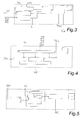
- the control system for operating an ego vehicle with at least one prime mover on a route during approaching and passing one or several traffic lights comprises an information and receiver and sensorics module A, a situation analyzer module B, a constraint handler module C, a real time optimization module D, a human machine interface module E and a vehicle level module F.
- the route travelled consists of road segments, the respective segments being defined as areas between traffic lights or other static objects.
- the system continuously and iteratively performs the method according to the invention during operation of the ego vehicle.
- the receiver and sensorics module A collects information from the environment by corresponding sensorics, e.g., the position and sequence of traffic lights or the scheduling of their green or red phases, respectively, thereby creating a data map of the traffic lights.
- the system functions when the ego-vehicle is operated but could also be activated only upon driver acceptance DA.
- the vehicle gets in item 1 infrastructure information (e.g., via v2i-communication), preferably multiple traffic light scheduling signals 1a, of surrounding traffic lights and their scheduling (instant time of green/red phase, length of time of green/red phase, transition periods between green and red phases, maybe in the form of a orange/yellow phase, possible change of rhythm of green phases, and so on).
- the vehicle gathers information (e.g., via v2i-communication, using footage of external traffic cameras, etc.) of average traffic speed in upcoming road segments.
- the traffic light positions are scheduled in a map.
- map data 3 and updated positioning data 4 of a GPS (global positioning system) of the ego vehicle the distance between the ego vehicle and the traffic lights is estimated (item 5).
- Further information from surrounding vehicles maybe collected via v2v-communication (item 6, optionally) and via front/rear camera and/or radar devices (item 7).
- Other environmental information e.g., weather, road conditions, etc.
- the data traffic light scheduling TLS, average upcoming speed AUS on the route ahead (in road segments ahead), map data MD, updated distances to traffic lights UDTL, position of the ego vehicle PEV, information about surrounding vehicles ISV, etc. are inputted to the situation analyzer module B (see Fig. 3 ).
- the situation analyzer module B If all environmental and traffic information is available, the situation is analyzed in the situation analyzer module B, taking the traffic, weather and other environmental information into account. First the situation analyzer module B conducts a quick check of the situation to calculate green phases ("gaps") of each traffic light and screens how to target it with a proper trajectory of the vehicle.
- Item 8 catches the time-space distribution of crossing gaps, processing the information about the traffic lights and yielding their position and time of their "gaps", i.e., green phases, and the respective distance of the vehicle. As a result multiple possible trajectories through the traffic lights ahead are determined.
- a microscopic traffic condition analyzer 9 takes into account vehicles directly ahead and behind and provides a short distance acceleration trajectory.
- a macroscopic traffic condition analyzer 12 takes into account the average speed of upcoming road segments considering other vehicles information (e.g. via v2i-communication, traffic management systems with cameras, etc.), weather conditions, and so on.
- the macroscopic traffic condition analyzer 12 provides a long distance acceleration trajectory.
- a first optimization (minimizing/maximizing cost function) of the acceleration trajectory for the green phases of traffic lights ahead based on the information from the preceding items 8, 9 and 12 is conducted to go through traffic lights on a green wave.
- Item 10 does not yet consider any power-train information of the ego-vehicle.
- item 11 makes a selection of the most beneficial fitting green phase gap combination for all traffic light ahead as a result of the optimization of item 10 ("corridor").
- Beneficial means searching for gaps at traffic lights ahead that allow for smooth passing of said lights without or minimum number of stops. For example at first traffic light the first green phase may be targeted, at second traffic light its third green phase and at third traffic light the tenth green phase.
- the result of situation analyzer module B is the information in which time window the ego vehicle needs to be at which position (i.e. at which traffic light at which green phase) in order to pass through all the gaps chosen in module B.
- a time-corridor is defined in which the vehicle has to pass certain positions, i.e., the traffic lights.
- the term "corridor” here signifies that even though the green phases to target at each traffic light are fixed the exact time when to pass it during the selected green phase remains to be decided. This leaves lots of time-space combinations, i.e., a time-place-corridor.
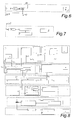
- the time gap selection TGS as well as constraint information CI about possible constraints modification are inputted to the next instance, i.e. the constraint handler module C (see Fig. 4 ). To make sure that all available information is used, updated constraint information is constantly included in subsequent steps. Further inputs of constraint handler module C are traffic light scheduling TLS, average upcoming speed AUS, map data MD, position of the ego vehicle PEV, Information about surrounding vehicles ISV, on board information OBI, and other.
- the constraint handler module C defines constraints (i.e. boundaries of the corridor mentioned in situation analyzer module B) that have to be included into any optimization.
- the constraint information includes power-train information and vehicle information like battery status information, speed, position, tire pressure, efficiency of electric machine or combustion engine.
- the constraint handler module C converts the measurement of preceding steps into formats that can be processed by a controller (e.g., conversion of traffic light phases into time).
- Item 13 comprises a mathematical step, collecting and converting signals into usable values/formats for optimization routine (see a real time optimization module D, item 19).
- Item 14 defines power-train constraints, taken from on-board information OBI (e.g., for an electric machine: recuperation is limited by maximum possible torque, available battery charge, available torque, etc.).
- OBI on-board information
- Item 15 creates speed constraints, e.g., speed limits that have to be obeyed, average speed from item 12, microscopic information from item 9; constraints of reality (optimization routine could yield an optimal speed below 0, which is not convenient in the real world).
- speed constraints e.g., speed limits that have to be obeyed, average speed from item 12, microscopic information from item 9; constraints of reality (optimization routine could yield an optimal speed below 0, which is not convenient in the real world).
- Item 16 creates position versus time constraints.
- the ego-vehicle at a certain time has to be at a certain position. So item 16 of the constraint handler module C assesses position and time to stay in optimized trajectory corridor, wherein corridors which were not selected in items 10 and 11 are excluded to facilitate optimization.
- the ego-vehicle can be at a certain position within a certain timeframe (selected green phase)
- the result of the constraint handler module C are updated constraints UC, which are inputted to the real time optimization module D.
- the real time optimization module D yields an acceleration trajectory based on the constraints UC of the constraint handler module C being updated continuously (see 19b) and the on board information OBI with vehicle status information (vehicle speed, vehicle position, battery information, efficiency of electric machine).
- vehicle status information vehicle speed, vehicle position, battery information, efficiency of electric machine.
- the corridor selected before is narrowed down to the optimized velocity profile and acceleration trajectory.
- Item 19 includes the real time optimization 19a, wherein all available information is optimized into an acceleration trajectory by taking power-train information into account and optimizing the trajectory for efficient power-train usage - contrary to prior art solutions which only generate velocity profiles which allow passing through green phases of traffic lights, the method according to the invention considers the efficiency (consumption, recuperation, torque, %) of the vehicle and its power-train and optimizes the trajectory for both green wave and efficient driving.
- item 19c includes a prediction module based on a longitudinal vehicle model and a power-train model to estimate the vehicle behaviour during overall manoeuvre. This module is updated at each instant with the new information obtained from earlier items and also with control inputs, resulting from the optimization routine including not only current optimal control signals but also the future control signals. This allows for consideration of future power-train behavior in the optimization.
- Control input here signifies all results from the optimization routine according to the invention that are applied to the power-train, e.g., a number of acceleration values.
- the longitudinal model of the vehicle is used to estimate the vehicle speed v and the position of the vehicle along the distance d for which the acceleration trajectory is optimized. This is directly used in the formulation of the optimization routine. This allows implicitly excluding speed profile possibilities that are not compatible with the selected corridor.
- the longitudinal vehicle model is a model that only considers the longitudinal dynamics of the vehicle because lateral dynamics do not have major impact on energy consumption. Hence, calculation of the optimization routine may be faster.
- this prediction is moving with the car position and estimates the vehicle position and vehicle speed v along the route. It means the longitudinal model runs all the time while the vehicle moves and predicts the positions and speed v and other characteristics of the vehicle.
- control horizon the optimization routine generates a new set of control inputs (control horizon) for the near future, taking into account the power-train's reaction to the control inputs calculated earlier, with one control input being applied to the power-train and the others being used for predicting the power-train's reaction as input for the next iteration of the method according to the invention.
- the power-train model works together with the longitudinal model. Since the longitudinal model calculates the vehicle position and speed it is possible also to calculate the power-train components' behavior during the time period ⁇ t using these quantities. For instance, at a certain time t, the optimization module D calculates a control input (desired acceleration) sequence: Desired acceleration: a(t), a(t+1), a(t+2), a(t+3)....a(t+ ⁇ t))
- this desired acceleration a can be converted into a speed sequence: Vehicle speed: v(t), v(t+1), v(t+2),v(t+3)....v(t+ ⁇ t)
- Vehicle speed v and acceleration a can easily be converted into power-train behavior (for example engine speed n, engine torque M) using a power-train model (gear ratios for power-train speed calculation, acceleration into force via vehicle longitudinal model and torque with power-train model):
- Engine speed n(t), n(t+1), n(t+2).
- n(t+ ⁇ t) Electric machine speed: n EM (t), n EM (t+1), n EM (t+2).
- Engine Torque M(t), M(t+1), M(t+2).
- Electric Machine Torque M EM (t), M EM (t+1), M EM (t+2).
- the power-train model is used to introduce power-train related constraints into the optimization calculation.
- the constraints are only valid for the current step time. In a new iteration of the optimization routine this constraint checking calculation, is repeated for the new conditions. Similar to the longitudinal model, the power-train model is repeatedly calculating the conditions ahead. This is mainly required because the estimation sequence must be forwarded ahead (one step, e.g., one time unit) to cover new conditions; also, if something changes ahead (e.g. a cut-in vehicle, changes in traffic or environmental conditions) the calculation and optimization must be carried out with new conditions.
- something changes ahead e.g. a cut-in vehicle, changes in traffic or environmental conditions
- This constraint handling can further be extended to electrical behavior of the component, maximum battery voltage, battery power etc. This depends on the complexity of the power-train model used in the vehicle.
- a second point where power-train model is used is for estimation of the energy behavior on the road ahead.
- Speed and torque values can be used to calculate the efficiencies ⁇ , ⁇ EM of components: Engine efficiency : ⁇ (t), ⁇ (t+1), ⁇ (t+2).... ⁇ (t+ ⁇ t)
- Electric machine efficiency : ⁇ EM (t), ⁇ EM (t+1), ⁇ EM (t+2).... ⁇ EM (t+ ⁇ t)
- the optimization routine uses a cost function to evaluate a metrics to define an optimal speed profile, this cost function must imply the energy consumption of the vehicle along the route ahead when the calculated velocity profile is applied.
- component efficiencies are used.
- the consumption e.g. gear ratios efficiencies, battery efficiencies, etc.
- All these behaviors are calculated using the power-train model.
- thermal behaviors, electrical behaviors or any other behaviors can be calculated: Those are the secondary factors influencing energy consumption, it depends on the power-train model complexity.
- the entire sequence is fed to item 19c to predict the vehicle's and its power-train's reaction to the values and to iteratively include this reaction into the next sequence of values when performing the optimization again.
- the human machine interface module E allows the driver to hand over control of the vehicle to a control system of the vehicle and to apply the green-wave-optimization.
- Item 17 signals the driver via a human machine interface module E that the traffic light assistant can be activated.
- this human machine interface module E could display instructions for the driver to implement the results of the method according to the invention.
- the driver is asked if he accept to use the traffic light assistant, i.e., agrees to apply the green-wave-optimization or not. If the driver chooses "no" the system signals in some display, acoustic signal, and so on further indicates the availability of the optimization (see SRP - "system is ready to be operated").
- the optimization takes control (e.g., the driver can take the foot off the gas pedal), the calculated inputs are applied (APP). It is also possible to automatically apply the results of the optimization without asking the driver's permission; this could be implemented for vehicles that drive autonomously or semiautonomously.
- the vehicle level module F translates the acceleration trajectory into a torque value for the prime mover, e.g., an electric machine or a combustion machine, using an arbitration module 24 to convert acceleration demands AC into torque demands TQ (item 22), in order to control a traction actuator or brake actuator (e.g. an electric machine), respectively (item 23).
- a prime mover e.g., an electric machine or a combustion machine
- an arbitration module 24 to convert acceleration demands AC into torque demands TQ (item 22), in order to control a traction actuator or brake actuator (e.g. an electric machine), respectively (item 23).
- the optimization routine begins with startup of the vehicle and continuously determines the optimal trajectory and acceleration trajectory by gathering environmental information and details about traffic, surrounding vehicles and road segments ahead. This information is used as input for the optimization routine which is iteratively performed during operation of the ego vehicle, resulting in a proposed velocity profile and acceleration trajectory.
- the optimization not only calculates a trajectory for immediate usage but also for the near future to iteratively assess its impact on the power-train and other vehicle characteristics, using their response as input for next iteration steps.
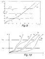
- Fig. 9 shows a diagram comparing the passing of traffic lights passes of a vehicle with and without using the inventive method, with the distance d and the time t of a travelling vehicle.
- the horizontal lines RP represent the timing of red phases of three upcoming traffic lights TL1, TL2, TL3 at specific positions.
- the gaps GP represent the timing of green phases of the three upcoming traffic lights TL1, TL2, TL3 at their specific positions.
- a generic trajectory T is chosen such that the vehicle selects the first upcoming green light phase at the first traffic light TL1, the third green light phase at second traffic light TL2 and the third green light phase at the third traffic light TL3.
- the dashed curve T0 depicts a vehicle without using the present method which has to stop at the first and third traffic lights TL1 and TL3.
- FIG. 10 shows an application of the method according to the invention in more detail.
- Another distance-time diagram in Fig. 10 shows five possible basic trajectories T1, T2, T3, T4, T5 for available gaps of two traffic lights TL1 and TL2 ahead, with the basic trajectories being determined by the situation analyzer module B.
- the basic trajectories T1, T2, T3, T4, T5 differ in which gaps at which traffic light TL1, TL2 they chose and how they approach the respective gap to pass the traffic light.
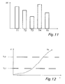
- step 10 an energy balance for each possible basic trajectory T1, T2, T3, T4, T5 is estimated.
- Fig. 11 shows the changes in energy ⁇ E (difference between energy spent energy and energy gained) per basic trajectory wherein the third basic trajectory T3 ( Fig. 12 ) is most beneficial and selected by/in item 11.
- ⁇ E difference between energy spent energy and energy gained
- the constraint handler (Item 14, 15 and 16) is used to narrow down the available corridor of the third basic trajectory T3, as indicated in Fig. 13 to 16 .
- Fig. 13 shows three striped boxes equaling the three road segments and time windows that are discussed in this simplified example of the method according to the invention.
- the first road segment is between the current position and the first traffic light TL2
- the second road segment is between the first TL1 and second traffic light TL2
- the third road segment is after the third traffic light TL3.
- Fig. 14 sub-divides the segments also considering the timing of the passing of the vehicle so the constraint handling and the optimization may allow selecting the optimum trajectory.
- the vehicle may be anywhere between its current position (which will be called "position 0" in the following) and the position of traffic light TL2.
- the vehicle may be anywhere between position 0 and the position of the second traffic light TL2.
- the vehicle may be anywhere between the first traffic light TL1 and the second traffic light TL2.
- the vehicle may be anywhere between the first traffic light TL1 and somewhere beyond the second traffic light TL2.
- Fig. 15 shows how the constraint handler C, particularly its items 14 and 15 delimit the available corridor based on speed constraints (speed limits, other vehicles, general average speed in available road segments) and power-train constraints (state of charge, ).
- Item 16 defines constraints for time (start time t 1 ; t 3 and end time t 2 ; t 4 of chosen green gap) and location (position of traffic light), marked in Fig. 15 by black circles.
Landscapes
- Engineering & Computer Science (AREA)
- Automation & Control Theory (AREA)
- Physics & Mathematics (AREA)
- Transportation (AREA)
- Mechanical Engineering (AREA)
- Life Sciences & Earth Sciences (AREA)
- Atmospheric Sciences (AREA)
- General Physics & Mathematics (AREA)
- Human Computer Interaction (AREA)
- Mathematical Physics (AREA)
- Electric Propulsion And Braking For Vehicles (AREA)
Priority Applications (1)
| Application Number | Priority Date | Filing Date | Title |
|---|---|---|---|
| EP14167936.5A EP2945140A1 (de) | 2014-05-12 | 2014-05-12 | System und Verfahren zum Betreiben eines Ökofahrzeugs |
Applications Claiming Priority (1)
| Application Number | Priority Date | Filing Date | Title |
|---|---|---|---|
| EP14167936.5A EP2945140A1 (de) | 2014-05-12 | 2014-05-12 | System und Verfahren zum Betreiben eines Ökofahrzeugs |
Publications (1)
| Publication Number | Publication Date |
|---|---|
| EP2945140A1 true EP2945140A1 (de) | 2015-11-18 |
Family
ID=50729363
Family Applications (1)
| Application Number | Title | Priority Date | Filing Date |
|---|---|---|---|
| EP14167936.5A Ceased EP2945140A1 (de) | 2014-05-12 | 2014-05-12 | System und Verfahren zum Betreiben eines Ökofahrzeugs |
Country Status (1)
| Country | Link |
|---|---|
| EP (1) | EP2945140A1 (de) |
Cited By (18)
| Publication number | Priority date | Publication date | Assignee | Title |
|---|---|---|---|---|
| FR3045545A1 (fr) * | 2015-12-21 | 2017-06-23 | Peugeot Citroen Automobiles Sa | Dispositif d’aide a la conduite |
| DE102016122001A1 (de) * | 2016-11-16 | 2018-05-17 | Dr. Ing. H.C. F. Porsche Aktiengesellschaft | Verfahren für die Erzeugung von Fahranweisungen für den Fahrer eines elektrisch angetriebenen Fahrzeugs |
| WO2018184413A1 (zh) * | 2017-04-07 | 2018-10-11 | 孟卫平 | 交通信号泛绿波控制方法 |
| FR3071197A1 (fr) * | 2017-09-15 | 2019-03-22 | Psa Automobiles Sa | Procede de determination d’une consigne de vitesse pour minimiser la consommation energetique d’un vehicule |
| WO2019140367A1 (en) * | 2018-01-15 | 2019-07-18 | Uber Technologies, Inc. | Discrete decision architecture for motion planning system of an autonomous vehicle |
| GB2572448A (en) * | 2018-03-30 | 2019-10-02 | Jaguar Land Rover Ltd | Vehicle control method and apparatus |
| EP3546309A1 (de) * | 2018-03-30 | 2019-10-02 | PSA Automobiles SA | Lenkassistenzverfahren und -vorrichtung eines fahrzeugs beim vorbeifahren an einer dreifarbigen ampel in abhängigkeit vom fahrerprofil |
| CN110546056A (zh) * | 2017-05-03 | 2019-12-06 | 斯堪尼亚商用车有限公司 | 用于确定车辆的控制方案的方法和控制装置 |
| EP3549838A4 (de) * | 2016-11-29 | 2019-12-11 | Mazda Motor Corporation | Fahrzeugsteuerungsvorrichtung |
| CN111439249A (zh) * | 2019-01-16 | 2020-07-24 | 通用汽车环球科技运作有限责任公司 | 利用预览信息的动力系统的模型预测控制 |
| US10773597B2 (en) | 2017-10-06 | 2020-09-15 | Ford Global Technologies, Llc | Autonomous vehicle acceleration profile |
| CN111667719A (zh) * | 2019-04-25 | 2020-09-15 | 文远知行有限公司 | 用于控制自动驾驶车辆的速度的设备和方法及存储介质 |
| CN112525210A (zh) * | 2020-11-24 | 2021-03-19 | 同济大学 | 一种面向节能的电动汽车全局路径和速度联合优化方法 |
| CN112580251A (zh) * | 2020-11-16 | 2021-03-30 | 北京理工大学 | 基于交通信息和模型预测控制的混动汽车能量管理方法 |
| WO2021107413A1 (ko) * | 2019-11-29 | 2021-06-03 | (주)언맨드솔루션 | 자율 주행 자동차 |
| US11390300B2 (en) | 2019-10-18 | 2022-07-19 | Uatc, Llc | Method for using lateral motion to optimize trajectories for autonomous vehicles |
| CN115107805A (zh) * | 2022-07-06 | 2022-09-27 | 山东科技大学 | 一种车辆轨迹规划方法、系统及设备 |
| EP4246486A1 (de) * | 2022-03-14 | 2023-09-20 | Garrett Transportation I Inc. | Beratungssysteme zum koordinierten passieren von verkehrsampeln |
Citations (11)
| Publication number | Priority date | Publication date | Assignee | Title |
|---|---|---|---|---|
| EP1127727A2 (de) * | 2000-02-23 | 2001-08-29 | Hitachi, Ltd. | Vorrichtung zur Fahrzeuggeschwindigkeitsregelung |
| US20080094250A1 (en) | 2006-10-19 | 2008-04-24 | David Myr | Multi-objective optimization for real time traffic light control and navigation systems for urban saturated networks |
| JP2008296798A (ja) | 2007-06-01 | 2008-12-11 | Denso Corp | 車両の制御装置 |
| DE102008037883A1 (de) | 2007-08-30 | 2009-04-09 | Continental Teves Ag & Co. Ohg | Verkehrsleitsystem |
| DE102008061303A1 (de) | 2007-12-11 | 2009-06-18 | Continental Teves Ag & Co. Ohg | Fahrzeugsteuerung unter Verwendung von Fahrzeug-zu-Fahrzeug-Kommunikation |
| US20100088002A1 (en) | 2008-10-07 | 2010-04-08 | Welte Gregory A | System for increasing fuel economy in vehicles |
| WO2011163006A1 (en) | 2010-06-23 | 2011-12-29 | On Time Systems, Inc. | Traffic routing display system |
| US20120109421A1 (en) | 2010-11-03 | 2012-05-03 | Kenneth Scarola | Traffic congestion reduction system |
| DE102011081609A1 (de) * | 2011-08-26 | 2013-02-28 | Robert Bosch Gmbh | Verfahren und Vorrichtung zur Bewertung einer Annäherungssituation eines Fahrzeugs an eine Signalanlage |
| US8478500B1 (en) * | 2009-09-01 | 2013-07-02 | Clemson University | System and method for utilizing traffic signal information for improving fuel economy and reducing trip time |
| DE102013110346A1 (de) * | 2012-10-02 | 2014-04-03 | Avl List Gmbh | Verfahren zum Betreiben eines Antriebsstranges |
-
2014
- 2014-05-12 EP EP14167936.5A patent/EP2945140A1/de not_active Ceased
Patent Citations (11)
| Publication number | Priority date | Publication date | Assignee | Title |
|---|---|---|---|---|
| EP1127727A2 (de) * | 2000-02-23 | 2001-08-29 | Hitachi, Ltd. | Vorrichtung zur Fahrzeuggeschwindigkeitsregelung |
| US20080094250A1 (en) | 2006-10-19 | 2008-04-24 | David Myr | Multi-objective optimization for real time traffic light control and navigation systems for urban saturated networks |
| JP2008296798A (ja) | 2007-06-01 | 2008-12-11 | Denso Corp | 車両の制御装置 |
| DE102008037883A1 (de) | 2007-08-30 | 2009-04-09 | Continental Teves Ag & Co. Ohg | Verkehrsleitsystem |
| DE102008061303A1 (de) | 2007-12-11 | 2009-06-18 | Continental Teves Ag & Co. Ohg | Fahrzeugsteuerung unter Verwendung von Fahrzeug-zu-Fahrzeug-Kommunikation |
| US20100088002A1 (en) | 2008-10-07 | 2010-04-08 | Welte Gregory A | System for increasing fuel economy in vehicles |
| US8478500B1 (en) * | 2009-09-01 | 2013-07-02 | Clemson University | System and method for utilizing traffic signal information for improving fuel economy and reducing trip time |
| WO2011163006A1 (en) | 2010-06-23 | 2011-12-29 | On Time Systems, Inc. | Traffic routing display system |
| US20120109421A1 (en) | 2010-11-03 | 2012-05-03 | Kenneth Scarola | Traffic congestion reduction system |
| DE102011081609A1 (de) * | 2011-08-26 | 2013-02-28 | Robert Bosch Gmbh | Verfahren und Vorrichtung zur Bewertung einer Annäherungssituation eines Fahrzeugs an eine Signalanlage |
| DE102013110346A1 (de) * | 2012-10-02 | 2014-04-03 | Avl List Gmbh | Verfahren zum Betreiben eines Antriebsstranges |
Non-Patent Citations (2)
| Title |
|---|
| DE NUNZIO GIOVANNI ET AL: "Eco-driving in urban traffic networks using traffic signal information", 52ND IEEE CONFERENCE ON DECISION AND CONTROL, IEEE, 10 December 2013 (2013-12-10), pages 892 - 898, XP032577057, ISSN: 0743-1546, ISBN: 978-1-4673-5714-2, [retrieved on 20140307], DOI: 10.1109/CDC.2013.6759995 * |
| FELICITAS MENSING ET AL: "Trajectory optimization for eco-driving taking into account traffic constraints", TRANSPORTATION RESEARCH PART D: TRANSPORT AND ENVIRONMENT, vol. 18, 1 January 2013 (2013-01-01), pages 55 - 61, XP055132596, ISSN: 1361-9209, DOI: 10.1016/j.trd.2012.10.003 * |
Cited By (32)
| Publication number | Priority date | Publication date | Assignee | Title |
|---|---|---|---|---|
| FR3045545A1 (fr) * | 2015-12-21 | 2017-06-23 | Peugeot Citroen Automobiles Sa | Dispositif d’aide a la conduite |
| US10495477B2 (en) | 2016-11-16 | 2019-12-03 | Dr. Ing. h.c. F. Porsche Aktiengsellschaft | Method for generating driving instructions for the driver of an electrically driven vehicle |
| DE102016122001A1 (de) * | 2016-11-16 | 2018-05-17 | Dr. Ing. H.C. F. Porsche Aktiengesellschaft | Verfahren für die Erzeugung von Fahranweisungen für den Fahrer eines elektrisch angetriebenen Fahrzeugs |
| EP3549838A4 (de) * | 2016-11-29 | 2019-12-11 | Mazda Motor Corporation | Fahrzeugsteuerungsvorrichtung |
| WO2018184413A1 (zh) * | 2017-04-07 | 2018-10-11 | 孟卫平 | 交通信号泛绿波控制方法 |
| US11685388B2 (en) | 2017-05-03 | 2023-06-27 | Scania Cv Ab | Method and a control arrangement for determining a control profile for a vehicle |
| EP3619085A4 (de) * | 2017-05-03 | 2021-03-31 | Scania CV AB | Verfahren und steueranordnung zur bestimmung eines steuerungsprofils für ein fahrzeug |
| CN110546056A (zh) * | 2017-05-03 | 2019-12-06 | 斯堪尼亚商用车有限公司 | 用于确定车辆的控制方案的方法和控制装置 |
| FR3071197A1 (fr) * | 2017-09-15 | 2019-03-22 | Psa Automobiles Sa | Procede de determination d’une consigne de vitesse pour minimiser la consommation energetique d’un vehicule |
| US10773597B2 (en) | 2017-10-06 | 2020-09-15 | Ford Global Technologies, Llc | Autonomous vehicle acceleration profile |
| US11262756B2 (en) | 2018-01-15 | 2022-03-01 | Uatc, Llc | Discrete decision architecture for motion planning system of an autonomous vehicle |
| US12045054B2 (en) | 2018-01-15 | 2024-07-23 | Uatc, Llc | Discrete decision architecture for motion planning system of an autonomous vehicle |
| WO2019140367A1 (en) * | 2018-01-15 | 2019-07-18 | Uber Technologies, Inc. | Discrete decision architecture for motion planning system of an autonomous vehicle |
| GB2572448B (en) * | 2018-03-30 | 2021-02-03 | Jaguar Land Rover Ltd | Vehicle control method and apparatus |
| EP3546309A1 (de) * | 2018-03-30 | 2019-10-02 | PSA Automobiles SA | Lenkassistenzverfahren und -vorrichtung eines fahrzeugs beim vorbeifahren an einer dreifarbigen ampel in abhängigkeit vom fahrerprofil |
| CN111867911A (zh) * | 2018-03-30 | 2020-10-30 | 捷豹路虎有限公司 | 车辆控制方法和设备 |
| GB2572448A (en) * | 2018-03-30 | 2019-10-02 | Jaguar Land Rover Ltd | Vehicle control method and apparatus |
| CN110335483A (zh) * | 2018-03-30 | 2019-10-15 | 标致雪铁龙汽车股份有限公司 | 根据驾驶员简档在通过交通灯时辅助车辆驾驶的方法和装置 |
| FR3079488A1 (fr) * | 2018-03-30 | 2019-10-04 | Psa Automobiles Sa | Procede et dispositif d’assistance a la conduite d’un vehicule lors d’un passage de feu tricolore, en fonction du profil du conducteur |
| CN111867911B (zh) * | 2018-03-30 | 2024-05-17 | 捷豹路虎有限公司 | 车辆控制方法和设备 |
| US11858513B2 (en) | 2018-03-30 | 2024-01-02 | Jaguar Land Rover Limited | Vehicle target operational speed band control method and apparatus |
| CN111439249A (zh) * | 2019-01-16 | 2020-07-24 | 通用汽车环球科技运作有限责任公司 | 利用预览信息的动力系统的模型预测控制 |
| CN111439249B (zh) * | 2019-01-16 | 2023-10-20 | 通用汽车环球科技运作有限责任公司 | 利用预览信息的动力系统的模型预测控制 |
| CN111667719A (zh) * | 2019-04-25 | 2020-09-15 | 文远知行有限公司 | 用于控制自动驾驶车辆的速度的设备和方法及存储介质 |
| US11390300B2 (en) | 2019-10-18 | 2022-07-19 | Uatc, Llc | Method for using lateral motion to optimize trajectories for autonomous vehicles |
| WO2021107413A1 (ko) * | 2019-11-29 | 2021-06-03 | (주)언맨드솔루션 | 자율 주행 자동차 |
| CN112580251A (zh) * | 2020-11-16 | 2021-03-30 | 北京理工大学 | 基于交通信息和模型预测控制的混动汽车能量管理方法 |
| CN112580251B (zh) * | 2020-11-16 | 2022-07-12 | 北京理工大学 | 基于交通信息和模型预测控制的混动汽车能量管理方法 |
| CN112525210B (zh) * | 2020-11-24 | 2022-09-16 | 同济大学 | 一种面向节能的电动汽车全局路径和速度联合优化方法 |
| CN112525210A (zh) * | 2020-11-24 | 2021-03-19 | 同济大学 | 一种面向节能的电动汽车全局路径和速度联合优化方法 |
| EP4246486A1 (de) * | 2022-03-14 | 2023-09-20 | Garrett Transportation I Inc. | Beratungssysteme zum koordinierten passieren von verkehrsampeln |
| CN115107805A (zh) * | 2022-07-06 | 2022-09-27 | 山东科技大学 | 一种车辆轨迹规划方法、系统及设备 |
Similar Documents
| Publication | Publication Date | Title |
|---|---|---|
| EP2945140A1 (de) | System und Verfahren zum Betreiben eines Ökofahrzeugs | |
| US11288963B2 (en) | Autonomous vehicles featuring vehicle intention system | |
| US12061088B2 (en) | Obstacle avoidance method and apparatus | |
| CN111656295B (zh) | 用于自主运载工具的对象交互预测系统及方法 | |
| US10346888B2 (en) | Systems and methods to obtain passenger feedback in response to autonomous vehicle driving events | |
| US11568689B2 (en) | Systems and methods to obtain feedback in response to autonomous vehicle failure events | |
| CN110562258B (zh) | 一种车辆自动换道决策的方法、车载设备和存储介质 | |
| CN103347757B (zh) | 通过使用预测环境和驾驶员行为信息来优化燃油经济性的系统和方法 | |
| US20200372793A1 (en) | Method, Device, and System of Dynamic Allocation of Traffic Resources | |
| US11585669B2 (en) | Vehicle routing using connected data analytics platform | |
| Zhang et al. | Predictive eco-driving application considering real-world traffic flow | |
| CA3193121A1 (en) | Method and apparatus for coordinating multiple cooperative vehicle trajectories on shared road networks | |
| CN112829762A (zh) | 一种车辆行驶速度生成方法以及相关设备 | |
| CN113272750A (zh) | 一种交通拥堵辅助驾驶方法、系统、车载设备和存储介质 | |
| CN114822048A (zh) | 一种网联车的云端规划服务系统及方法 | |
| CN109993965B (zh) | 目标速度计算方法及装置、mec服务器及存储介质 | |
| CN111683852A (zh) | 车辆控制系统、车辆控制方法及程序 | |
| US12043085B2 (en) | Emergency heating system for electric vehicle (EV) running out of power | |
| EP4386510A1 (de) | Verfahren und systeme zur handhabung von okklusionen beim betrieb eines autonomen fahrzeugs | |
| CN117944684B (zh) | 变道轨迹规划方法和装置、存储介质及电子设备 | |
| US20240075923A1 (en) | Systems and methods for deweighting veering margins based on crossing time | |
| US20240017744A1 (en) | Operational weather management | |
| US20240116511A1 (en) | Multi-policy lane change assistance for vehicle | |
| EP4140844A2 (de) | Persistieren von vorhergesagten objekten für robustheit gegenüber wahrnehmungsproblemen beim autonomen fahren | |
| CN116994450A (zh) | 一种对于网联车提供自动驾驶服务的方法及装置 |
Legal Events
| Date | Code | Title | Description |
|---|---|---|---|
| PUAI | Public reference made under article 153(3) epc to a published international application that has entered the european phase |
Free format text: ORIGINAL CODE: 0009012 |
|
| AK | Designated contracting states |
Kind code of ref document: A1 Designated state(s): AL AT BE BG CH CY CZ DE DK EE ES FI FR GB GR HR HU IE IS IT LI LT LU LV MC MK MT NL NO PL PT RO RS SE SI SK SM TR |
|
| AX | Request for extension of the european patent |
Extension state: BA ME |
|
| 17P | Request for examination filed |
Effective date: 20160518 |
|
| RBV | Designated contracting states (corrected) |
Designated state(s): AL AT BE BG CH CY CZ DE DK EE ES FI FR GB GR HR HU IE IS IT LI LT LU LV MC MK MT NL NO PL PT RO RS SE SI SK SM TR |
|
| 17Q | First examination report despatched |
Effective date: 20180208 |
|
| 17Q | First examination report despatched |
Effective date: 20180215 |
|
| STAA | Information on the status of an ep patent application or granted ep patent |
Free format text: STATUS: THE APPLICATION HAS BEEN REFUSED |
|
| 18R | Application refused |
Effective date: 20191208 |