EP2944746A1 - Fastener - Google Patents
Fastener Download PDFInfo
- Publication number
- EP2944746A1 EP2944746A1 EP15165168.4A EP15165168A EP2944746A1 EP 2944746 A1 EP2944746 A1 EP 2944746A1 EP 15165168 A EP15165168 A EP 15165168A EP 2944746 A1 EP2944746 A1 EP 2944746A1
- Authority
- EP
- European Patent Office
- Prior art keywords
- clamping lever
- closure
- pressure plate
- closure according
- base plate
- Prior art date
- Legal status (The legal status is an assumption and is not a legal conclusion. Google has not performed a legal analysis and makes no representation as to the accuracy of the status listed.)
- Granted
Links
- 230000007613 environmental effect Effects 0.000 claims abstract description 12
- 230000000903 blocking effect Effects 0.000 claims description 2
- 230000037431 insertion Effects 0.000 claims 1
- 238000003780 insertion Methods 0.000 claims 1
- 230000007257 malfunction Effects 0.000 abstract description 4
- 206010053648 Vascular occlusion Diseases 0.000 description 6
- 230000006835 compression Effects 0.000 description 3
- 238000007906 compression Methods 0.000 description 3
- 230000013011 mating Effects 0.000 description 2
- 239000002184 metal Substances 0.000 description 2
- 238000000034 method Methods 0.000 description 2
- 230000000007 visual effect Effects 0.000 description 2
- 241000272814 Anser sp. Species 0.000 description 1
- 230000005540 biological transmission Effects 0.000 description 1
- 238000010276 construction Methods 0.000 description 1
- 238000006073 displacement reaction Methods 0.000 description 1
- 238000005096 rolling process Methods 0.000 description 1
- 238000007493 shaping process Methods 0.000 description 1
Images


Classifications
-
- E—FIXED CONSTRUCTIONS
- E05—LOCKS; KEYS; WINDOW OR DOOR FITTINGS; SAFES
- E05B—LOCKS; ACCESSORIES THEREFOR; HANDCUFFS
- E05B17/00—Accessories in connection with locks
- E05B17/0025—Devices for forcing the wing firmly against its seat or to initiate the opening of the wing
-
- E—FIXED CONSTRUCTIONS
- E05—LOCKS; KEYS; WINDOW OR DOOR FITTINGS; SAFES
- E05B—LOCKS; ACCESSORIES THEREFOR; HANDCUFFS
- E05B1/00—Knobs or handles for wings; Knobs, handles, or press buttons for locks or latches on wings
- E05B1/0092—Moving otherwise than only rectilinearly or only rotatively
-
- E—FIXED CONSTRUCTIONS
- E05—LOCKS; KEYS; WINDOW OR DOOR FITTINGS; SAFES
- E05B—LOCKS; ACCESSORIES THEREFOR; HANDCUFFS
- E05B41/00—Locks with visible indication as to whether the lock is locked or unlocked
-
- E—FIXED CONSTRUCTIONS
- E05—LOCKS; KEYS; WINDOW OR DOOR FITTINGS; SAFES
- E05C—BOLTS OR FASTENING DEVICES FOR WINGS, SPECIALLY FOR DOORS OR WINDOWS
- E05C5/00—Fastening devices with bolts moving otherwise than only rectilinearly and only pivotally or rotatively
- E05C5/02—Fastening devices with bolts moving otherwise than only rectilinearly and only pivotally or rotatively both moving axially and turning about their axis to secure the wing
Definitions
- the invention relates to a closure for releasably connecting a cover element with an environmental structure. In many applications, it is desirable to quickly and securely connect lid members to the environmental structure.
- connection of a cover element with the surrounding structure is a conventional screw connection, for example by means of hexagon screws and lock washers.
- the problem with this inexpensive connection are the slow assembly and disassembly and the lack of rapid visual control. Thus, it is not easy to see, with a visual check, whether the fitting has been tightened correctly, that is, the correct torque has been applied during tightening.
- quick release clamps eg Camloc tension locks
- compression rotary bolt locks such as those of the Company Southco are offered in use.
- the object of the invention is to develop a generic closure such that it connects not only a cover element quickly and safely releasably connected to an environmental structure, with a mechanical security or first level of security is also provided here. Rather, the closure should still have a real integrated second mechanical security level, which completely prevents a malfunction that could result from incorrect operation of the closure.
- the closed or open position of the closure should also be visually recognizable, even from a distance.
- a closure for detachably connecting a cover element is provided with an environmental structure having a clamping lever which is pivotally connected to an armature such that by pivoting the clamping lever, the lid member with the surrounding structure is connectable, wherein the clamping lever via a through in its side walls provided openings hin tellsteckbaren safety pin in the closed state is securable.
- a pivotable pivoting element integrated in the closure of the cover element is pivotable out of a position in the mold so that the path between the openings provided in the side walls of the tensioning lever is blocked by the pivoting element when the clamping lever is closed but not correctly connected.
- the pivoting element is advantageously part of a pivotable pressure plate, which is held by a spring assembly in a blocking starting position, wherein the pressure plate is pivoted with correct connection of the cover element with the surrounding structure against the force of the spring assembly in an end position releasing the area between the opening.
- the pressure plate also can not be supported on the surrounding structure, so as to counteract the force of Spring package to provide a pivoting of the pivoting element.
- the armature is defined in a base plate rotatably and displaceably guided.
- the anchor can be mounted with the clamping lever in the correct position on the cover element.
- the rotational or displacement movement of the armature can be fixed.
- the pressure plate is pivotally mounted in the base plate.
- a corresponding slot may be provided in the base plate, through which passes a part of the pressure plate bent through 90 °, wherein the pressure plate on the base plate over widened shoulders (stop) can be supported laterally.
- the base plate may have an upwardly bent nose, which serves as a guide during the closing of the clamping lever.
- the guide takes place in that the side walls of the clamping lever when pivoting down are guided laterally along the side wall of the bent nose.
- the pivoting element is designed as a gooseneck-shaped web on the front part of the pressure plate.
- a slot may be excluded, in which the gooseneck-shaped web of the pivotal pressure plate is accommodated. This results in a particularly stable embodiment variant.
- the gooseneck-shaped web together with the inserted securing bolt secure the clamping lever in its closed position.
- At least one projection can be integrally formed on the clamping lever, which dips when closing the clamping lever in a corresponding recess. As a result, a lateral rotation of the clamping lever is effectively prevented even with corresponding lateral forces in the closed position.
- FIG. 1 is a perspective view of a closure 10 according to an embodiment of the present invention, with which a lid member not shown here in detail with an environmental structure is releasably connectable.
- the closure 10 has a clamping lever 12, which in the illustration according to FIG. 1 partially cut away to represent the entire mechanism.
- the clamping lever 12 is pivotally connected via a bolt 14 with an armature 16.
- the armature 16 is guided rotatably and displaceably in a base plate 18.
- the clamping lever 12 is designed as a curved sheet metal construction and has on the bolt 14 each side of the armature 16 eccentric surfaces 20 on which it is ensured that when pivoting down the clamping lever 12 of the armature 16 is moved in the vertical direction.
- the base plate 18 has both-sided slots 22. By screws not shown here, the base plate can be adjusted over the slots and bolted to the cover element also not shown here.
- the base plate 18 has an upwardly bent nose 24, which serves as a guide during the closing of the clamping lever 12. When closed, the bent nose 24 secures the clamping lever 12 enclosing it against lateral loading.
- the closure 10 also has a pressure plate 26 pivotally connected to the base plate 18. With its rear part, which is bent up by 90 °, the pressure plate 26 by a according FIG. 2 slot 28 shown in the base plate 18 and mounted on a shoulder-like widened stop 30 pivotally mounted relative to the base plate.
- the armature 16 is also passed through the pressure plate 26, wherein the armature 16 is rotatable and displaceable.
- the front end of the pressure plate 26 is formed in the form of a gooseneck-shaped web 32.
- This gooseneck-shaped web 32 is slidably guided in a formed in the nose 24 of the base plate 18 central slot.
- the pressure plate 26 with the gooseneck-shaped web 32 forms a mechanical security element, which ensures the correct connection of a cover element with an environmental structure.
- cup spring package 34 which is threaded onto the shaft of the armature 16.
- a second level of security consists in the fact that the locking bolt 38 can only be inserted through the corresponding openings 36 in the side walls of the clamping lever 12 when the closure 10 has really been properly closed. This reliably precludes a malfunction of the closure 10.
- the clamping lever 12 of the closure 10 In the open state, the clamping lever 12 of the closure 10 is in a lying position normal to the plane of symmetry of the base plate 18.
- the armature 16 is applied to the pressure plate 26 at.
- To close the clamping lever 12 is initially opened, which is due to the eccentric rolling curve of the cam surfaces 20 of the clamping lever 12, the anchor lowers and is introduced into the opposite profile of the surrounding structure.
- the cover element is not directly itself, but at each closure position only on the underside of the pressure plate 26 on the opposite profile of the environmental structure on the outside.
- the unfolded position of the clamping lever 12 In the unfolded position of the clamping lever 12 is now rotated counterclockwise by 90 ° and thus the armature 16 within the mating profile of the surrounding structure, as the basis of the FIG. 6 is shown.
- the armature By folding down the clamping lever 12 and positioning the clamping lever 12 designed as a hollow sheet metal structure over the nose 24 of the base plate 18 in the lying position, the armature is now pulled back over the eccentric discs 20 and thus presses the pressure plate against the intermediate profile wall of the surrounding structure Disc spring package 34.
- the closing force of the clamping lever 12 and the biasing force of the closure 10 is thus defined by the compression of the disc spring package 34.
- the front gooseneck-shaped web 32 is raised.
- the correctly closed state of the closure 10 is defined by the openings 36 through hole of the clamping lever for receiving the securing bolt 38 is released.
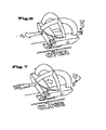
- FIG. 6 schematically shows the kinematics of the shutter 10 when opening.
- the safety pin 38 is pulled out in the direction of arrow 1.
- the clamping lever 12 is pivoted upwards and rotated by 90 °. Finally he is panned down again.
- the armature 16 can now be pulled out through the corresponding slot-shaped opening in the surrounding structure, which is to be connected to the cover element.
- FIG. 7 shows the closing process.
- the armature 16 is initially positioned over the clamping lever 12 so that it can be passed through the corresponding slot opening.
- the clamping lever of the armature 16 is pivoted down and passed through the slot of the surrounding structure.
- the armature 16 is tightened again and the surrounding structure is firmly connected to the lid member.
- Anschmanend the locking pin 38 is inserted in the direction of arrow 2.
Landscapes
- Engineering & Computer Science (AREA)
- Mechanical Engineering (AREA)
- Pressure Vessels And Lids Thereof (AREA)
- Processing Of Stones Or Stones Resemblance Materials (AREA)
- Forms Removed On Construction Sites Or Auxiliary Members Thereof (AREA)
- Clamps And Clips (AREA)
- Operating, Guiding And Securing Of Roll- Type Closing Members (AREA)
Abstract
Die Erfindung betrifft einen Verschluss (10) zum lösbaren Verbinden eines Deckelelementes mit einer Umgebungsstruktur mit einem Spannhebel (12), der mit einem Anker (16) derart schwenkbar verbunden ist, dass durch Verschwenken des Spannhebels (12) das Deckelelement mit der Umgebungsstruktur verbindbar ist, wobei der Spannhebel (12) im geschlossenen Zustand über einen durch in seinen Seitenwandungen vorgesehenen Öffnungen (36) hindurchsteckbaren Sicherungsbolzen (38) sicherbar ist. Erfindungsgemäß ist ein beim Verschließen des Deckelelementes verschwenkbares Schwenkelement (26) aus einer Position herausschwenkbar, in der es den Weg zwischen den in den Seitenwandungen des Spannhebels (12) vorgesehenen Öffnungen (36) blockiert. Hierdurch kann eine integrierte echte zweite mechanische Sicherungsebene geschaffen werden, welche eine Fehlfunktion durch Fehlbedienung des Verschlusses (10) komplett verhindert.The invention relates to a closure (10) for detachably connecting a cover element to an environmental structure with a tensioning lever (12) which is pivotably connected to an armature (16) in such a way that the cover element can be connected to the surrounding structure by pivoting the tensioning lever (12) , In the closed state, the tensioning lever (12) can be secured via a securing pin (38) which can be pushed through through openings (36) provided in its side walls. According to the invention, a swivel element (26) pivotable when the lid element is closed can be pivoted out of a position in which it blocks the path between the openings (36) provided in the side walls of the clamping lever (12). In this way, an integrated genuine second mechanical security level can be created, which completely prevents a malfunction due to incorrect operation of the closure (10).
Description
Die Erfindung betrifft einen Verschluss zum lösbaren Verbinden eines Deckelelementes mit einer Umgebungsstruktur. Bei vielen Anwendungen ist es wünschenswert, Deckelelemente schnell und sicher mit der Umgebungsstruktur lösbar zu verbinden.The invention relates to a closure for releasably connecting a cover element with an environmental structure. In many applications, it is desirable to quickly and securely connect lid members to the environmental structure.
Die gängigste Verbindungsart eines Deckelelements mit der Umgebungsstruktur ist eine konventionelle Verschraubung, beispielsweise mittels Sechskantschrauben und Sicherungsscheiben. Problematisch bei dieser preisgünstigen Verbindungsart sind jedoch die langsame Montage und Demontage und die fehlende rasche visuelle Kontrollmöglichkeit. So lässt sich nicht mit einer visuellen Kontrolle ohne weiteres erkennen, ob die Verschraubung korrekt angezogen wurde, das heißt das richtige Drehmoment während des Anziehens angewandt wurde.The most common type of connection of a cover element with the surrounding structure is a conventional screw connection, for example by means of hexagon screws and lock washers. The problem with this inexpensive connection, however, are the slow assembly and disassembly and the lack of rapid visual control. Thus, it is not easy to see, with a visual check, whether the fitting has been tightened correctly, that is, the correct torque has been applied during tightening.
Zum lösbaren Verbinden von Deckelelementen mit einer Umgebungsstruktur sind aber auch bereits unterschiedliche Schnellverschlüsse im Einsatz. Hier gibt es sogenannte Schnellspanner (beispielsweise Camloc Spannverschlüsse). Zum anderen sind auch Kompressions-Drehriegelverschlüsse, wie sie beispielsweise von der Firma Southco angeboten werden, in Verwendung. Diese vorbekannten Schnellverschlüsse ermöglichen zwar eine rasche Handhabung, verfügen aber über höchstens eine integrierte mechanische Sicherheitsebene, welche den Zustand des Verschlusses (offen / geschlossen) eindeutig definiert. Der korrekte Verbund durch diese Schnellverschlüsse ist nur bedingt visuell kontrollierbar und damit deren eigentliche Primärfunktion mit dem Verschluss in sich alleine nicht sichergestellt.For the detachable connection of cover elements with an environmental structure, however, different quick-release closures are already in use. There are so-called quick release clamps (eg Camloc tension locks). On the other hand, compression rotary bolt locks, such as those of the Company Southco are offered in use. Although these prior art quick releases allow for rapid handling, but have at most an integrated mechanical security level, which clearly defines the state of the closure (open / closed). The correct connection through these quick-release fasteners is only conditionally visually controllable and thus their actual primary function with the closure alone is not ensured.
Aufgabe der Erfindung ist es, einen gattungsgemäßen Verschluss derart weiterzubilden, dass er nicht nur ein Deckelelement schnell und sicher mit einer Umgebungsstruktur lösbar verbindet, wobei auch hier eine mechanische Sicherung oder erste Sicherheitsebene vorgesehen wird. Vielmehr soll der Verschluss noch über eine echte integrierte zweite mechanische Sicherungsebene verfügen, welche eine Fehlfunktion gänzlich verhindert, die durch eine Fehlbedienung des Verschlusses erfolgen resultieren könnte. Die Geschlossen- bzw. Offenposition des Verschlusses sollte zudem visuell, auch aus größerer Entfernung sofort erkennbar sein.The object of the invention is to develop a generic closure such that it connects not only a cover element quickly and safely releasably connected to an environmental structure, with a mechanical security or first level of security is also provided here. Rather, the closure should still have a real integrated second mechanical security level, which completely prevents a malfunction that could result from incorrect operation of the closure. The closed or open position of the closure should also be visually recognizable, even from a distance.
Erfindungsgemäß wird diese Aufgabe bei einem gattungsgemäßen Verschluss durch die Kombination der Merkmale des Anspruchs 1 gelöst.This object is achieved in a generic closure by the combination of the features of claim 1.
Hier ist ein Verschluss zum lösbaren Verbinden eines Deckelelementes mit einer Umgebungsstruktur geschaffen, welcher einen Spannhebel aufweist, der mit einem Anker derart schwenkbar verbunden ist, dass durch Verschwenken des Spannhebels das Deckelelement mit der Umgebungsstruktur verbindbar ist, wobei der Spannhebel über einen durch in seinen Seitenwandungen vorgesehenen Öffnungen hindurchsteckbaren Sicherungsbolzen im geschlossenen Zustand sicherbar ist. Erfindungsgemäß ist ein beim Verschließen des Deckelelements integriertes verschwenkbares Schwenkelement aus einer Position heraus in der Form schwenkbar, dass bei geschlossenem Spannhebel aber nicht korrektem Verbund der Weg zwischen den in den Seitenwandungen des Spannhebels vorgesehenen Öffnungen durch das Schwenkelement blockiert wird. Durch das Vorsehen des verschwenkbaren Schwenkelementes ist bei dem Verschluss somit eine integrierte echte zweite mechanische Sicherungsebene geschaffen worden, welche eine Fehlfunktion durch Fehlbedienung des Verschlusses komplett verhindert. Die Lösung besteht hier in einer besonderen Kombination aus Kompressionsdreh- und Spannhebelprinzip, wobei ein integriertes Schwenkelement vorgesehen ist, das lediglich beim korrekten Verschließen des Deckelelementes den Weg zum Einstecken eines Sicherungsbolzens freigibt.Here, a closure for detachably connecting a cover element is provided with an environmental structure having a clamping lever which is pivotally connected to an armature such that by pivoting the clamping lever, the lid member with the surrounding structure is connectable, wherein the clamping lever via a through in its side walls provided openings hindurchsteckbaren safety pin in the closed state is securable. According to the invention, a pivotable pivoting element integrated in the closure of the cover element is pivotable out of a position in the mold so that the path between the openings provided in the side walls of the tensioning lever is blocked by the pivoting element when the clamping lever is closed but not correctly connected. By providing the pivotable pivoting element, an integrated genuine second mechanical locking plane has thus been created in the closure, which is a malfunction completely prevented by incorrect operation of the closure. The solution here consists in a special combination of Kompressionsdreh- and tension lever principle, wherein an integrated pivot member is provided, which releases the way to insert a locking bolt only when correctly closing the lid member.
Bevorzugte Ausgestaltungen der Erfindung ergeben sich aus den sich an den Hauptanspruch anschließenden Unteransprüchen.Preferred embodiments of the invention will become apparent from the subsequent claims to the main claim.
Demnach ist das Schwenkelement vorteilhaft Teil einer schwenkbaren Druckplatte, welche über ein Federpaket in einer blockierenden Ausgangsstellung gehalten wird, wobei die Druckplatte bei korrektem Verbinden des Deckelementes mit der Umgebungsstruktur gegen die Kraft des Federpaketes in einer den Bereich zwischen der Öffnung freigebenden Endstellung verschwenkbar ist. Beim Verbinden des Deckelelementes mit der Umgebungsstruktur wird während des Anziehens des Ankers bei entsprechendem Verschwenken des Spannhebels die Druckplatte, welche sich an der Umgebungsstruktur abstützt, gegen die Federkraft verschwenkt, wodurch gleichzeitig das Schwenkelement unter Freigabe des Bereichs zwischen den Öffnungen des Spannhebels nach oben verschwenkt wird. Dieses Verschwenken gegen die Kraft der Federpakete ist allerdings nur dann möglich, wenn sich die Druckplatte tatsächlich auf der Umgebungsstruktur abstützt. Falls beispielsweise der Anker beim Verschließen des Verschlusses versehentlich nicht in die korrekte Position unterhalb der Umgebungsstruktur positioniert wird und so beim Verschwenken des Spannhebels sich nicht an der Umgebungsstruktur abstützen kann, kann sich die Druckplatte ebenfalls nicht an der Umgebungsstruktur abstützen, um so entgegen der Kraft des Federpaketes zu einem Verschwenken des Schwenkelementes zu sorgen.Accordingly, the pivoting element is advantageously part of a pivotable pressure plate, which is held by a spring assembly in a blocking starting position, wherein the pressure plate is pivoted with correct connection of the cover element with the surrounding structure against the force of the spring assembly in an end position releasing the area between the opening. When connecting the lid member with the surrounding structure, the pressure plate, which is supported on the surrounding structure, pivoted against the spring force during the attraction of the armature with a corresponding pivoting of the clamping lever, whereby at the same time the pivot member is pivoted releasing the area between the openings of the clamping lever upwards , However, this pivoting against the force of the spring packs is only possible if the pressure plate is actually supported on the surrounding structure. For example, if the anchor is accidentally not positioned in the correct position below the surrounding structure when closing the shutter and so can not support the surrounding structure during pivoting of the clamping lever, the pressure plate also can not be supported on the surrounding structure, so as to counteract the force of Spring package to provide a pivoting of the pivoting element.
Besonders vorteilhaft ist der Anker in einer Grundplatte definiert dreh- und verschiebbar geführt. Über die Grundplatte kann der Anker mit dem Spannhebel in korrekter Position auf dem Deckelelement montiert werden. Über entsprechende Aussparungen bzw. durch entsprechende Formgebung der Ausnehmung, durch welche der entsprechend formangepasste Anker hindurchgesteckt wird, ist die Dreh- bzw. Verschiebebewegung des Ankers festlegbar.Particularly advantageously, the armature is defined in a base plate rotatably and displaceably guided. About the base plate, the anchor can be mounted with the clamping lever in the correct position on the cover element. About corresponding recesses or by appropriate shaping of the recess, through which the suitably shaped anchor is inserted therethrough, the rotational or displacement movement of the armature can be fixed.
Gemäß einer weiteren vorteilhaften Ausgestaltung der Erfindung ist die Druckplatte schwenkbar in der Grundplatte gelagert. Hierzu kann ein entsprechender Schlitz in der Grundplatte vorgesehen sein, durch welche ein Teil der um 90° gebogenen Druckplatte hindurchtritt, wobei sich die Druckplatte auf der Grundplatte über verbreiterte Schultern (Anschlag) seitlich abstützen kann.According to a further advantageous embodiment of the invention, the pressure plate is pivotally mounted in the base plate. For this purpose, a corresponding slot may be provided in the base plate, through which passes a part of the pressure plate bent through 90 °, wherein the pressure plate on the base plate over widened shoulders (stop) can be supported laterally.
Die Grundplatte kann eine nach oben gebogene Nase aufweisen, welche während des Schließens des Spannhebels als Führung dient. Die Führung erfolgt dadurch, dass die Seitenwandungen des Spannhebels beim Herabschwenken seitlich entlang der Seitenwandung der gebogenen Nase geführt werden.The base plate may have an upwardly bent nose, which serves as a guide during the closing of the clamping lever. The guide takes place in that the side walls of the clamping lever when pivoting down are guided laterally along the side wall of the bent nose.
Vorzugsweise ist das Schwenkelement als schwanenhalsförmiger Steg am Vorderteil der Druckplatte ausgebildet.Preferably, the pivoting element is designed as a gooseneck-shaped web on the front part of the pressure plate.
In der gebogenen Nase der Grundplatte kann ein Schlitz ausgenommen sein, in welchem der schwanenhalsförmige Steg der schwenkbaren Druckplatte aufgenommen ist. Hierdurch ergibt sich eine besonders stabile Ausführungsvariante.In the curved nose of the base plate, a slot may be excluded, in which the gooseneck-shaped web of the pivotal pressure plate is accommodated. This results in a particularly stable embodiment variant.
Vorteilhaft kann der schwanenhalsförmige Steg zusammen mit dem gesteckten Sicherungsbolzen den Spannhebel in seiner geschlossenen Stellung sichern.Advantageously, the gooseneck-shaped web together with the inserted securing bolt secure the clamping lever in its closed position.
Weiterhin kann am Spannhebel mindestens ein Vorsprung angeformt sein, der beim Schließen des Spannhebels in eine entsprechende Ausnehmung eintaucht. Hierdurch ist ein seitliches Verdrehen des Spannhebels auch bei entsprechend auftretenden Seitenkräften in geschlossener Stellung wirksam verhindert.Furthermore, at least one projection can be integrally formed on the clamping lever, which dips when closing the clamping lever in a corresponding recess. As a result, a lateral rotation of the clamping lever is effectively prevented even with corresponding lateral forces in the closed position.
Weitere Merkmale, Einzelheiten und Vorteile der Erfindung ergeben sich aus einem in der Zeichnung dargestellten Ausführungsbeispiel. Es zeigen:
- Figur 1:
- eine teilweise geschnittene perspektivische Darstellung einer Ausführungsform des erfindungsgemäßen Verschlusses;
- Figur 2:
- eine seitliche Darstellung des Verschlusses im Schnitt;
- Figur 3:
- eine Ansicht des Verschlusses von vorne;
- Figur 4:
- eine seitliche Darstellung des Verschlusses;
- Figur 5:
- eine Darstellung des Verschlusses von oben und
- Figuren 6 und 7:
- eine Darstellung des Verschlusses, die die Kinematik während des Öffnens und Verschließens zeigen.
- FIG. 1:
- a partially sectioned perspective view of an embodiment of the closure according to the invention;
- FIG. 2:
- a side view of the closure in section;
- FIG. 3:
- a view of the closure from the front;
- FIG. 4:
- a side view of the closure;
- FIG. 5:
- a representation of the closure from above and
- FIGS. 6 and 7:
- a representation of the closure, showing the kinematics during opening and closing.
In der
Der Spannhebel 12 ist als gebogene Blechkonstruktion ausgeführt und weist auf dem Bolzen 14 jeweils seitlich des Ankers 16 Exzenterflächen 20 auf, über die sichergestellt ist, dass beim Herabschwenken des Spannhebels 12 der Anker 16 in vertikaler Richtung bewegt wird.The clamping
Die Grundplatte 18 verfügt über beidseitige Langlöcher 22. Durch hier nicht näher dargestellte Schrauben kann die Grundplatte über die Langlöcher justiert und mit dem hier ebenfalls nicht dargestellten Deckelelement fest verschraubt werden.The
Die Grundplatte 18 weist eine nach oben gebogene Nase 24 auf, welche während des Schließens dem Spannhebel 12 als Führung dient. Im geschlossenen Zustand sichert die gebogene Nase 24 den diese umschließenden Spannhebel 12 gegen seitliche Belastung.The
Der Verschluss 10 weist darüber hinaus eine schwenkbar mit der Grundplatte 18 verbundene Druckplatte 26 auf. Mit ihrem hinteren Teil, der um 90° hochgebogen ist, ist die Druckplatte 26 durch einen gemäß
Wie insbesondere im Querschnitt gemäß
Das vordere Ende der Druckplatte 26 ist in Form eines schwanenhalsförmigen Stegs 32 ausgebildet. Dieser schwanenhalsförmige Steg 32 ist verschieblich in einem in der Nase 24 der Grundplatte 18 gebildeten mittigen Schlitz geführt. Die Druckplatte 26 mit dem schwanenhalsförmigen Steg 32 bildet ein mechanisches Sicherheitselement, welches das korrekte Verbinden eines Deckelelementes mit einer Umgebungsstruktur sicherstellt.The front end of the
Zwischen der Grundplatte 18 und der Druckplatte 26 befindet sich ein Tellerfedernpaket 34, welches auf dem Schaft des Ankers 16 aufgefädelt ist.Between the
Wie aus der Schnittzeichnung gemäß
Eine zweite Sicherheitsebene besteht nun darin, dass der Sicherungsbolzen 38 nur dann durch die entsprechenden Öffnungen 36 in den Seitenwandungen des Spannhebels 12 gesteckt werden kann, wenn der Verschluss 10 auch wirklich korrekt geschlossen wurde. Hiermit wird eine Fehlfunktion des Verschlusses 10 sicher ausgeschlossen.A second level of security consists in the fact that the locking
Im Folgenden wird die zweite Sicherheitsebene über die Beschreibung des Schließvorgangs erklärt.In the following, the second level of security is explained by the description of the closing process.
In geöffnetem Zustand befindet sich der Spannhebel 12 des Verschlusses 10 in liegender Position normal zur Symmetrieebene der Grundplatte 18. Der Anker 16 liegt an der Druckplatte 26 an. Zum Verschließen wird der Spannhebel 12 zunächst aufgeklappt, wodurch sich aufgrund der exzentrischen Abrollkurve der Exzenterflächen 20 des Spannhebels 12 der Anker absenkt und in das Gegenprofil der Umgebungsstruktur eingeführt wird. Das Deckelelement liegt nicht unmittelbar selbst, sondern bei jeder Verschlussposition nur über der Unterseite der Druckplatte 26 auf dem Gegenprofil der Umgebungsstruktur außen auf. In der aufgeklappten Position wird der Spannhebel 12 nun gegen den Uhrzeigersinn um 90° verdreht und damit auch der Anker 16 innerhalb des Gegenprofils der Umgebungsstruktur, wie die anhand der
Durch Herunterklappen des Spannhebels 12 und Positionieren des als hohle Blechstruktur ausgeführten Spannhebels 12 über der Nase 24 der Grundplatte 18 in die liegende Position wird nun der Anker über die Exzenterscheiben 20 wieder nach oben gezogen und presst somit über die dazwischenliegende Gegenprofilwand der Umgebungsstruktur die Druckplatte gegen das Tellerfedernpaket 34. Die Schließkraft des Spannhebels 12 bzw. die Vorspannkraft des Verschlusses 10 wird also durch das Zusammenpressen des Tellerfedernpakets 34 definiert. Gleichzeitig wird während des Schließvorgangs durch das Pressen der Druckplatte 26 über deren hintere Schwenkachse im Schlitz 28 mit der Grundplatte 18, der vordere schwanenhalsförmige Steg 32 angehoben. Im korrekt geschlossenen Zustand des Verschlusses 10 wird durch die Öffnungen 36 definierte Durchgangsbohrung des Spannhebels für die Aufnahme des Sicherungsbolzens 38 freigegeben.By folding down the clamping
Im Fall einer Fehlbedienung, wenn beispielsweise der Anker 16 nicht unter das Gegenprofil der Umgebungsstruktur greift, liegt der Anker 16 mit seiner Unterseite außen am Gegenprofil der Umgebungsstruktur auf. Beim Herunterklappen des Spannhebels 12 in der geschlossenen Position wird der Anker 16 zwar angezogen. Es erfolgt aber durch das Fehlen der Gegenprofilwand der Umgebungsstruktur zwischen Anker 16 und Druckplatte 26 keine Kraftübertragung auf die Druckplatte 26 und somit auch kein Zusammenpressen der Tellerfedern des Tellerfedernpakets 34 statt. Damit erfolgt auch keine Schwenkbewegung der Druckplatte, sodass der vordere schwanenhalsförmige Steg 32 der Druckplatte 26 seine Position nicht verändert und damit nicht die Durchgangsbohrung zwischen den Öffnungen 36 des liegenden Spannhebels 12 freigibt. Somit ist es nicht mehr möglich, dass bei nicht korrekt durchgeführten Schließvorgang der Sicherungsbolzen 38 durch den Hebel gesteckt wird.In the case of a faulty operation, for example, when the
Die
Der Anker 16 kann nun durch die entsprechend langlochförmige Öffnung in der Umgebungsstruktur, die mit dem Deckelelement zu verbinden ist, herausgezogen werden.The
Claims (9)
dadurch gekennzeichnet,
dass ein beim Verbinden des Deckelelementes mit einer Umgebungsstruktur verschwenkbares Schwenkelement aus einer Position herausschwenkbar ist, in der es den Weg zwischen den in den Seitenwandungen des Spannhebels vorgesehenen Öffnungen zum Durchstecken des Sicherungshebels blockiert.Closure for releasably connecting a cover element with an environmental structure with a clamping lever which is pivotally connected to an armature such that the cover element can be connected to the environmental structure by pivoting the tensioning lever, wherein the clamping lever in the closed state can be pushed through an opening provided in its side walls Securing bolt is securable,
characterized,
in that a pivoting element, which can be pivoted when the cover element is connected to an environmental structure, can be pivoted out of a position in which it blocks the path between the openings provided in the side walls of the tensioning lever for insertion of the safety lever.
Priority Applications (1)
| Application Number | Priority Date | Filing Date | Title |
|---|---|---|---|
| PL15165168T PL2944746T3 (en) | 2014-05-13 | 2015-04-27 | Fastener |
Applications Claiming Priority (1)
| Application Number | Priority Date | Filing Date | Title |
|---|---|---|---|
| DE102014007017.4A DE102014007017A1 (en) | 2014-05-13 | 2014-05-13 | shutter |
Publications (2)
| Publication Number | Publication Date |
|---|---|
| EP2944746A1 true EP2944746A1 (en) | 2015-11-18 |
| EP2944746B1 EP2944746B1 (en) | 2017-11-22 |
Family
ID=53269298
Family Applications (1)
| Application Number | Title | Priority Date | Filing Date |
|---|---|---|---|
| EP15165168.4A Active EP2944746B1 (en) | 2014-05-13 | 2015-04-27 | Fastener |
Country Status (5)
| Country | Link |
|---|---|
| EP (1) | EP2944746B1 (en) |
| CN (1) | CN105090177B (en) |
| DE (1) | DE102014007017A1 (en) |
| ES (1) | ES2660255T3 (en) |
| PL (1) | PL2944746T3 (en) |
Citations (6)
| Publication number | Priority date | Publication date | Assignee | Title |
|---|---|---|---|---|
| US3402958A (en) * | 1967-03-28 | 1968-09-24 | Southco | Door or panel fastener |
| US4613099A (en) * | 1982-02-05 | 1986-09-23 | The Boeing Company | Latch signal and cowling structure |
| US5409272A (en) * | 1993-06-28 | 1995-04-25 | Southco, Inc. | Over-center latch assembly |
| BE1013598A3 (en) * | 2000-07-17 | 2002-04-02 | John Albers | Locking system |
| DE4395052B4 (en) * | 1992-10-14 | 2006-10-05 | Pro Quip International Pty.Ltd., Bayswater | Canister with lid arrangement |
| US20080129056A1 (en) * | 2006-11-30 | 2008-06-05 | Hartwell Corporation | Command Latch and Pin Latch System |
Family Cites Families (5)
| Publication number | Priority date | Publication date | Assignee | Title |
|---|---|---|---|---|
| DE1963768U (en) * | 1967-04-13 | 1967-07-06 | Otto Keseberg Press Stanz U Zi | TOGGLE LOCK FOR BARRELS, CRATES AND OTHER CONTAINERS. |
| DE8222226U1 (en) * | 1982-08-06 | 1982-10-14 | Fa. Theodor Schemm, 5952 Attendorn | Tension lever lock for a ring to close a barrel |
| DE19526477C1 (en) * | 1995-07-20 | 1996-09-12 | Jetbag Gmbh | Holder for detachable fastening of roof storage boxes on motor vehicles |
| DE29916175U1 (en) * | 1999-09-14 | 2000-11-16 | Impress Metal Packaging GmbH & Co. oHG, 38723 Seesen | Locking device with mechanically insertable fuse |
| CN2484387Y (en) * | 2001-07-04 | 2002-04-03 | 郑景源 | Suitcase lock with open-close state display |
-
2014
- 2014-05-13 DE DE102014007017.4A patent/DE102014007017A1/en not_active Withdrawn
-
2015
- 2015-04-27 EP EP15165168.4A patent/EP2944746B1/en active Active
- 2015-04-27 PL PL15165168T patent/PL2944746T3/en unknown
- 2015-04-27 ES ES15165168.4T patent/ES2660255T3/en active Active
- 2015-05-13 CN CN201510240412.7A patent/CN105090177B/en active Active
Patent Citations (6)
| Publication number | Priority date | Publication date | Assignee | Title |
|---|---|---|---|---|
| US3402958A (en) * | 1967-03-28 | 1968-09-24 | Southco | Door or panel fastener |
| US4613099A (en) * | 1982-02-05 | 1986-09-23 | The Boeing Company | Latch signal and cowling structure |
| DE4395052B4 (en) * | 1992-10-14 | 2006-10-05 | Pro Quip International Pty.Ltd., Bayswater | Canister with lid arrangement |
| US5409272A (en) * | 1993-06-28 | 1995-04-25 | Southco, Inc. | Over-center latch assembly |
| BE1013598A3 (en) * | 2000-07-17 | 2002-04-02 | John Albers | Locking system |
| US20080129056A1 (en) * | 2006-11-30 | 2008-06-05 | Hartwell Corporation | Command Latch and Pin Latch System |
Also Published As
| Publication number | Publication date |
|---|---|
| CN105090177B (en) | 2018-08-21 |
| PL2944746T3 (en) | 2018-04-30 |
| ES2660255T3 (en) | 2018-03-21 |
| EP2944746B1 (en) | 2017-11-22 |
| CN105090177A (en) | 2015-11-25 |
| DE102014007017A1 (en) | 2015-11-19 |
Similar Documents
| Publication | Publication Date | Title |
|---|---|---|
| DE102005002782B4 (en) | Fastening device for securing a freight container with a limiting mechanism | |
| WO2017063945A1 (en) | Hinge closure | |
| EP1274908B1 (en) | Lock for assembly in an opening in a thin wall | |
| DE60111286T2 (en) | Door closing arrangement for double doors | |
| WO2005090723A1 (en) | Adjusting device for rotating and tilting bolts | |
| AT15577U1 (en) | Tape for a door or a window | |
| EP3277899A1 (en) | Door handle assembly for a motor vehicle | |
| DE69921835T2 (en) | LOCK | |
| DE102013100922A1 (en) | Running part for guiding a furniture part in a guide direction via a guide rail and furniture fitting | |
| EP2944746B1 (en) | Fastener | |
| DE102010034498B4 (en) | Shockproof quick release fastener for the end fitting of a seat belt | |
| WO2007087945A1 (en) | Hinge assembly for the articulated connection of a door leaf, a window casement or similar to a frame | |
| EP3621484A2 (en) | Holding device for a front panel of a drawer | |
| EP2774869A1 (en) | Container lock | |
| DE3345814A1 (en) | Device for automatically safeguarding against the incorrect operation of an adjusting rod provided on a window or suchlike wing | |
| DE931727C (en) | Fitting consisting of two parts for the detachable connection of two parts, especially furniture parts | |
| EP4045744B1 (en) | Fitting arrangement | |
| DE202004001868U1 (en) | Lock, especially for furniture, has cylinder casing separate from and guidable by lock casing | |
| DE868563C (en) | Door lock for cars | |
| WO2022242801A1 (en) | Catch comprising a locking wedge | |
| WO2022242802A1 (en) | Locking device with rotation limiter | |
| AT205372B (en) | Tilt and turn hardware for windows and doors | |
| DE1923600C3 (en) | Fitting for windows, doors or the like, especially for turn-tilt sashes | |
| WO2022184208A1 (en) | Heat pump | |
| AT160657B (en) | Locking device for gas-tight room closures. |
Legal Events
| Date | Code | Title | Description |
|---|---|---|---|
| PUAI | Public reference made under article 153(3) epc to a published international application that has entered the european phase |
Free format text: ORIGINAL CODE: 0009012 |
|
| AK | Designated contracting states |
Kind code of ref document: A1 Designated state(s): AL AT BE BG CH CY CZ DE DK EE ES FI FR GB GR HR HU IE IS IT LI LT LU LV MC MK MT NL NO PL PT RO RS SE SI SK SM TR |
|
| AX | Request for extension of the european patent |
Extension state: BA ME |
|
| 17P | Request for examination filed |
Effective date: 20160509 |
|
| GRAP | Despatch of communication of intention to grant a patent |
Free format text: ORIGINAL CODE: EPIDOSNIGR1 |
|
| RIC1 | Information provided on ipc code assigned before grant |
Ipc: E05B 41/00 20060101AFI20170522BHEP Ipc: E05C 5/02 20060101ALI20170522BHEP |
|
| INTG | Intention to grant announced |
Effective date: 20170621 |
|
| GRAS | Grant fee paid |
Free format text: ORIGINAL CODE: EPIDOSNIGR3 |
|
| GRAA | (expected) grant |
Free format text: ORIGINAL CODE: 0009210 |
|
| AK | Designated contracting states |
Kind code of ref document: B1 Designated state(s): AL AT BE BG CH CY CZ DE DK EE ES FI FR GB GR HR HU IE IS IT LI LT LU LV MC MK MT NL NO PL PT RO RS SE SI SK SM TR |
|
| REG | Reference to a national code |
Ref country code: GB Ref legal event code: FG4D Free format text: NOT ENGLISH |
|
| REG | Reference to a national code |
Ref country code: CH Ref legal event code: EP |
|
| REG | Reference to a national code |
Ref country code: IE Ref legal event code: FG4D Free format text: LANGUAGE OF EP DOCUMENT: GERMAN |
|
| REG | Reference to a national code |
Ref country code: AT Ref legal event code: REF Ref document number: 948566 Country of ref document: AT Kind code of ref document: T Effective date: 20171215 |
|
| REG | Reference to a national code |
Ref country code: DE Ref legal event code: R096 Ref document number: 502015002372 Country of ref document: DE |
|
| REG | Reference to a national code |
Ref country code: CH Ref legal event code: NV Representative=s name: KELLER AND PARTNER PATENTANWAELTE AG, CH |
|
| REG | Reference to a national code |
Ref country code: ES Ref legal event code: FG2A Ref document number: 2660255 Country of ref document: ES Kind code of ref document: T3 Effective date: 20180321 |
|
| REG | Reference to a national code |
Ref country code: NL Ref legal event code: MP Effective date: 20171122 |
|
| REG | Reference to a national code |
Ref country code: LT Ref legal event code: MG4D |
|
| REG | Reference to a national code |
Ref country code: FR Ref legal event code: PLFP Year of fee payment: 4 |
|
| PG25 | Lapsed in a contracting state [announced via postgrant information from national office to epo] |
Ref country code: NL Free format text: LAPSE BECAUSE OF FAILURE TO SUBMIT A TRANSLATION OF THE DESCRIPTION OR TO PAY THE FEE WITHIN THE PRESCRIBED TIME-LIMIT Effective date: 20171122 Ref country code: NO Free format text: LAPSE BECAUSE OF FAILURE TO SUBMIT A TRANSLATION OF THE DESCRIPTION OR TO PAY THE FEE WITHIN THE PRESCRIBED TIME-LIMIT Effective date: 20180222 Ref country code: FI Free format text: LAPSE BECAUSE OF FAILURE TO SUBMIT A TRANSLATION OF THE DESCRIPTION OR TO PAY THE FEE WITHIN THE PRESCRIBED TIME-LIMIT Effective date: 20171122 Ref country code: LT Free format text: LAPSE BECAUSE OF FAILURE TO SUBMIT A TRANSLATION OF THE DESCRIPTION OR TO PAY THE FEE WITHIN THE PRESCRIBED TIME-LIMIT Effective date: 20171122 Ref country code: SE Free format text: LAPSE BECAUSE OF FAILURE TO SUBMIT A TRANSLATION OF THE DESCRIPTION OR TO PAY THE FEE WITHIN THE PRESCRIBED TIME-LIMIT Effective date: 20171122 |
|
| PG25 | Lapsed in a contracting state [announced via postgrant information from national office to epo] |
Ref country code: HR Free format text: LAPSE BECAUSE OF FAILURE TO SUBMIT A TRANSLATION OF THE DESCRIPTION OR TO PAY THE FEE WITHIN THE PRESCRIBED TIME-LIMIT Effective date: 20171122 Ref country code: RS Free format text: LAPSE BECAUSE OF FAILURE TO SUBMIT A TRANSLATION OF THE DESCRIPTION OR TO PAY THE FEE WITHIN THE PRESCRIBED TIME-LIMIT Effective date: 20171122 Ref country code: GR Free format text: LAPSE BECAUSE OF FAILURE TO SUBMIT A TRANSLATION OF THE DESCRIPTION OR TO PAY THE FEE WITHIN THE PRESCRIBED TIME-LIMIT Effective date: 20180223 Ref country code: BG Free format text: LAPSE BECAUSE OF FAILURE TO SUBMIT A TRANSLATION OF THE DESCRIPTION OR TO PAY THE FEE WITHIN THE PRESCRIBED TIME-LIMIT Effective date: 20180222 Ref country code: LV Free format text: LAPSE BECAUSE OF FAILURE TO SUBMIT A TRANSLATION OF THE DESCRIPTION OR TO PAY THE FEE WITHIN THE PRESCRIBED TIME-LIMIT Effective date: 20171122 |
|
| PG25 | Lapsed in a contracting state [announced via postgrant information from national office to epo] |
Ref country code: EE Free format text: LAPSE BECAUSE OF FAILURE TO SUBMIT A TRANSLATION OF THE DESCRIPTION OR TO PAY THE FEE WITHIN THE PRESCRIBED TIME-LIMIT Effective date: 20171122 Ref country code: CY Free format text: LAPSE BECAUSE OF FAILURE TO SUBMIT A TRANSLATION OF THE DESCRIPTION OR TO PAY THE FEE WITHIN THE PRESCRIBED TIME-LIMIT Effective date: 20171122 Ref country code: DK Free format text: LAPSE BECAUSE OF FAILURE TO SUBMIT A TRANSLATION OF THE DESCRIPTION OR TO PAY THE FEE WITHIN THE PRESCRIBED TIME-LIMIT Effective date: 20171122 Ref country code: SK Free format text: LAPSE BECAUSE OF FAILURE TO SUBMIT A TRANSLATION OF THE DESCRIPTION OR TO PAY THE FEE WITHIN THE PRESCRIBED TIME-LIMIT Effective date: 20171122 |
|
| REG | Reference to a national code |
Ref country code: DE Ref legal event code: R097 Ref document number: 502015002372 Country of ref document: DE |
|
| PG25 | Lapsed in a contracting state [announced via postgrant information from national office to epo] |
Ref country code: SM Free format text: LAPSE BECAUSE OF FAILURE TO SUBMIT A TRANSLATION OF THE DESCRIPTION OR TO PAY THE FEE WITHIN THE PRESCRIBED TIME-LIMIT Effective date: 20171122 Ref country code: RO Free format text: LAPSE BECAUSE OF FAILURE TO SUBMIT A TRANSLATION OF THE DESCRIPTION OR TO PAY THE FEE WITHIN THE PRESCRIBED TIME-LIMIT Effective date: 20171122 Ref country code: IT Free format text: LAPSE BECAUSE OF FAILURE TO SUBMIT A TRANSLATION OF THE DESCRIPTION OR TO PAY THE FEE WITHIN THE PRESCRIBED TIME-LIMIT Effective date: 20171122 |
|
| PG25 | Lapsed in a contracting state [announced via postgrant information from national office to epo] |
Ref country code: MT Free format text: LAPSE BECAUSE OF FAILURE TO SUBMIT A TRANSLATION OF THE DESCRIPTION OR TO PAY THE FEE WITHIN THE PRESCRIBED TIME-LIMIT Effective date: 20171122 |
|
| PLBE | No opposition filed within time limit |
Free format text: ORIGINAL CODE: 0009261 |
|
| STAA | Information on the status of an ep patent application or granted ep patent |
Free format text: STATUS: NO OPPOSITION FILED WITHIN TIME LIMIT |
|
| 26N | No opposition filed |
Effective date: 20180823 |
|
| PG25 | Lapsed in a contracting state [announced via postgrant information from national office to epo] |
Ref country code: SI Free format text: LAPSE BECAUSE OF FAILURE TO SUBMIT A TRANSLATION OF THE DESCRIPTION OR TO PAY THE FEE WITHIN THE PRESCRIBED TIME-LIMIT Effective date: 20171122 Ref country code: MC Free format text: LAPSE BECAUSE OF FAILURE TO SUBMIT A TRANSLATION OF THE DESCRIPTION OR TO PAY THE FEE WITHIN THE PRESCRIBED TIME-LIMIT Effective date: 20171122 |
|
| REG | Reference to a national code |
Ref country code: BE Ref legal event code: MM Effective date: 20180430 |
|
| REG | Reference to a national code |
Ref country code: IE Ref legal event code: MM4A |
|
| PG25 | Lapsed in a contracting state [announced via postgrant information from national office to epo] |
Ref country code: LU Free format text: LAPSE BECAUSE OF NON-PAYMENT OF DUE FEES Effective date: 20180427 |
|
| PG25 | Lapsed in a contracting state [announced via postgrant information from national office to epo] |
Ref country code: BE Free format text: LAPSE BECAUSE OF NON-PAYMENT OF DUE FEES Effective date: 20180430 |
|
| PG25 | Lapsed in a contracting state [announced via postgrant information from national office to epo] |
Ref country code: IE Free format text: LAPSE BECAUSE OF NON-PAYMENT OF DUE FEES Effective date: 20180427 |
|
| PG25 | Lapsed in a contracting state [announced via postgrant information from national office to epo] |
Ref country code: TR Free format text: LAPSE BECAUSE OF FAILURE TO SUBMIT A TRANSLATION OF THE DESCRIPTION OR TO PAY THE FEE WITHIN THE PRESCRIBED TIME-LIMIT Effective date: 20171122 |
|
| PG25 | Lapsed in a contracting state [announced via postgrant information from national office to epo] |
Ref country code: PT Free format text: LAPSE BECAUSE OF FAILURE TO SUBMIT A TRANSLATION OF THE DESCRIPTION OR TO PAY THE FEE WITHIN THE PRESCRIBED TIME-LIMIT Effective date: 20171122 |
|
| PG25 | Lapsed in a contracting state [announced via postgrant information from national office to epo] |
Ref country code: MK Free format text: LAPSE BECAUSE OF NON-PAYMENT OF DUE FEES Effective date: 20171122 Ref country code: HU Free format text: LAPSE BECAUSE OF FAILURE TO SUBMIT A TRANSLATION OF THE DESCRIPTION OR TO PAY THE FEE WITHIN THE PRESCRIBED TIME-LIMIT; INVALID AB INITIO Effective date: 20150427 |
|
| PG25 | Lapsed in a contracting state [announced via postgrant information from national office to epo] |
Ref country code: AL Free format text: LAPSE BECAUSE OF FAILURE TO SUBMIT A TRANSLATION OF THE DESCRIPTION OR TO PAY THE FEE WITHIN THE PRESCRIBED TIME-LIMIT Effective date: 20171122 Ref country code: IS Free format text: LAPSE BECAUSE OF FAILURE TO SUBMIT A TRANSLATION OF THE DESCRIPTION OR TO PAY THE FEE WITHIN THE PRESCRIBED TIME-LIMIT Effective date: 20180322 |
|
| REG | Reference to a national code |
Ref country code: CH Ref legal event code: PFA Owner name: LIEBHERR-TRANSPORTATION SYSTEMS GMBH AND CO. K, AT Free format text: FORMER OWNER: LIEBHERR-TRANSPORTATION SYSTEMS GMBH AND CO. KG, AT |
|
| PGFP | Annual fee paid to national office [announced via postgrant information from national office to epo] |
Ref country code: ES Payment date: 20220503 Year of fee payment: 8 |
|
| PGFP | Annual fee paid to national office [announced via postgrant information from national office to epo] |
Ref country code: CH Payment date: 20220419 Year of fee payment: 8 |
|
| PGFP | Annual fee paid to national office [announced via postgrant information from national office to epo] |
Ref country code: DE Payment date: 20230426 Year of fee payment: 9 |
|
| REG | Reference to a national code |
Ref country code: CH Ref legal event code: PL |
|
| PG25 | Lapsed in a contracting state [announced via postgrant information from national office to epo] |
Ref country code: LI Free format text: LAPSE BECAUSE OF NON-PAYMENT OF DUE FEES Effective date: 20230430 Ref country code: CH Free format text: LAPSE BECAUSE OF NON-PAYMENT OF DUE FEES Effective date: 20230430 |
|
| REG | Reference to a national code |
Ref country code: ES Ref legal event code: FD2A Effective date: 20240605 |
|
| PGFP | Annual fee paid to national office [announced via postgrant information from national office to epo] |
Ref country code: GB Payment date: 20240423 Year of fee payment: 10 |
|
| PG25 | Lapsed in a contracting state [announced via postgrant information from national office to epo] |
Ref country code: ES Free format text: LAPSE BECAUSE OF NON-PAYMENT OF DUE FEES Effective date: 20230428 |
|
| PGFP | Annual fee paid to national office [announced via postgrant information from national office to epo] |
Ref country code: AT Payment date: 20240425 Year of fee payment: 10 Ref country code: CZ Payment date: 20240424 Year of fee payment: 10 |
|
| PG25 | Lapsed in a contracting state [announced via postgrant information from national office to epo] |
Ref country code: ES Free format text: LAPSE BECAUSE OF NON-PAYMENT OF DUE FEES Effective date: 20230428 |
|
| PGFP | Annual fee paid to national office [announced via postgrant information from national office to epo] |
Ref country code: FR Payment date: 20240423 Year of fee payment: 10 |
|
| PGFP | Annual fee paid to national office [announced via postgrant information from national office to epo] |
Ref country code: PL Payment date: 20240423 Year of fee payment: 10 |