EP2944718B1 - Dampfbügeleisen - Google Patents
Dampfbügeleisen Download PDFInfo
- Publication number
- EP2944718B1 EP2944718B1 EP15166859.7A EP15166859A EP2944718B1 EP 2944718 B1 EP2944718 B1 EP 2944718B1 EP 15166859 A EP15166859 A EP 15166859A EP 2944718 B1 EP2944718 B1 EP 2944718B1
- Authority
- EP
- European Patent Office
- Prior art keywords
- steam
- heating
- water
- channel
- iron
- Prior art date
- Legal status (The legal status is an assumption and is not a legal conclusion. Google has not performed a legal analysis and makes no representation as to the accuracy of the status listed.)
- Active
Links
Images




Classifications
-
- D—TEXTILES; PAPER
- D06—TREATMENT OF TEXTILES OR THE LIKE; LAUNDERING; FLEXIBLE MATERIALS NOT OTHERWISE PROVIDED FOR
- D06F—LAUNDERING, DRYING, IRONING, PRESSING OR FOLDING TEXTILE ARTICLES
- D06F75/00—Hand irons
- D06F75/08—Hand irons internally heated by electricity
- D06F75/10—Hand irons internally heated by electricity with means for supplying steam to the article being ironed
- D06F75/12—Hand irons internally heated by electricity with means for supplying steam to the article being ironed the steam being produced from water supplied to the iron from an external source
-
- D—TEXTILES; PAPER
- D06—TREATMENT OF TEXTILES OR THE LIKE; LAUNDERING; FLEXIBLE MATERIALS NOT OTHERWISE PROVIDED FOR
- D06F—LAUNDERING, DRYING, IRONING, PRESSING OR FOLDING TEXTILE ARTICLES
- D06F75/00—Hand irons
- D06F75/08—Hand irons internally heated by electricity
- D06F75/24—Arrangements of the heating means within the iron; Arrangements for distributing, conducting or storing the heat
-
- D—TEXTILES; PAPER
- D06—TREATMENT OF TEXTILES OR THE LIKE; LAUNDERING; FLEXIBLE MATERIALS NOT OTHERWISE PROVIDED FOR
- D06F—LAUNDERING, DRYING, IRONING, PRESSING OR FOLDING TEXTILE ARTICLES
- D06F75/00—Hand irons
- D06F75/08—Hand irons internally heated by electricity
- D06F75/10—Hand irons internally heated by electricity with means for supplying steam to the article being ironed
- D06F75/20—Arrangements for discharging the steam to the article being ironed
Definitions
- the disclosure relates to an iron, and more particularly to a steam iron.
- US 5 367 799 A discloses an iron with fluid distributing fins.
- US 5 718 071 A discloses a steam iron with steam chamber ramp, puddle containment and surge drying wall.
- Conventional steam irons tend to have low heating efficiency where a relatively small, inconsistent amount of steam is generated per unit time. Such is insufficient to remove creases on clothes.
- a conventional steam iron is designed to utilize a two-stage heating process. First, water is initially pre-heated outside of the conventional steam iron to a certain temperature. Then, the pre-heated water is poured into the conventional steam iron to be further heated by an electric heating tube mounted therein. However, such heating process is relatively insufficient and energy-consuming.
- an object of the disclosure is to provide a steam iron that can alleviate at least one of the drawbacks of the prior arts.
- the steam iron includes an ironing unit.
- the ironing unit includes an ironing board member, a heating tube which is mounted fixedly in the ironing board member and which has left and right heating tube sections, and a housing which is mounted on top of the ironing board member.
- the steam iron is characterized in that the ironing board member is formed with a pre-heating channel, two heating channels, a steam channel and a plurality of spaced-apart steam vents.
- the pre-heating channel is formed between the left and right heating tube sections of the heating tube.
- the heating channels are in fluid communication with a rear end of the pre-heating channel, flank the pre-heating channel, extend forward and are disposed respectively and substantially over the left and right heating tube sections for heating the water coming from the pre-heating channel into steam.
- the steam channel is in fluid communication with front ends of the heating channels, and has two divisional sections flanking and being respectively adjacent to the heating channels, and extending rearward for spreading out the steam advanced from the heating channels.
- the steam vents are in spatial communication with and arranged along the divisional sections of the steam channel.
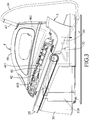
- an embodiment of a steam iron according to the disclosure includes a water tank unit 3 and an ironing unit 4.
- the ironing unit 4 includes an ironing board member 41 made of a metal material, a heating tube 45 mounted fixedly in the ironing board member 41 and having left and right heating tube sections 451, a housing 46 mounted on top of the ironing board member 41, and a linking tube 47 connected to the housing 46.
- the connecting pipe 34 of the water tank unit 3 interconnects the water pump 32 and the linking tube 47.
- Each of the left and right heating tube sections 451 has a front end. The front ends of the left and right heating tube sections 451 are connected to each other.
- the water tank unit 3 is connected to the linking tube 47, and is operable to pump water stored in the water reservoir 310 into the linking tube 47 by means of the water pump 32.
- the ironing board member 41 has an iron plate portion 411, a plurality of partitioning portions 417 and a plurality of protruding portions 418.
- the partitioning portions 417 extend upwardly from the iron plate portion 411, and cooperate with the iron plate portion 411 to define a pre-heating channel 42, two heating channels 43 and a steam channel 44.
- the pre-heating channel 42 is formed between the left and right heating tube sections 451 of the heating tube 45 (i.e., the pre-heating channel 42 is surrounded by the heating tube 45) for guiding water introduced therein from the linking tube 47 to be pre-heated by the left and right heating tube sections 451.
- the heating channels 43 are in fluid communication with a rear end of the pre-heating channel 42, flank the pre-heating channel 42, extend forward and are disposed respectively and substantially over the left and right heating tube sections 451 for heating the water coming from the pre-heating channel 42, thereby converting the water into steam.
- Each of the heating channels 43 has an S-shaped first heating section 431 that is connected to the rear end of the pre-heating channel 42, and a second heating section 432 that extends forward from the first heating section 431. Front ends of the second heating sections 432 of the heating channels 43 are connected to each other.
- first heating section 431 and a major part of the second heating section 432 are disposed above the left and right heating tube sections 451 for facilitating the abovementioned water-to-steam conversion.
- pre-heating channel 42 is disposed at an inner side of the heating channels 43, the high-temperature steam in the heating channels 43 also facilitates the pre-heating process in the pre-heating channel 42.
- the protruding portions 418 are spaced apart from each other, protrude upward from the iron plate portion 411 into the heating channels 43, and are symmetrically arranged. Each of the protruding portions 418 has a height smaller than that of the partitioning portions 417.
- each of the heating channels 43 is provided with three of the protruding portions 418. One of the protruding portions 418 in each heating channel 43 is disposed in the middle of the first heating section 431, and the remaining two of the protruding portions 418 are disposed in the second heating section 432. Due to the abovementioned structural design, the heating channels 43 are divided into a plurality of compartments 430 that are in fluid communication with each other. As such, flow of the water therein is slowed to allow the water to be sufficiently heated into steam.
- the steam channel 44 is in fluid communication with the front ends of the second heating sections 432 of the heating channels 43, and has two divisional sections 441 flanking and being respectively adjacent to the heating channels 43 and extending rearward for spreading out the steam coming from the heating channels 43.
- the iron plate portion 411 is formed with a plurality of steam vents 412 that extend therethrough, and that are in spatial communication with and arranged along the divisional sections 441 of the steam channel 44.
- the divisional sections 441 are disposed respectively on outer sides of the left and right heating tube sections 451, and are proximate to outer sides of the second heating sections 432.
- the heating tube 45 is fixed in the iron plate portion 411 below the pre-heating channel 42, the heating channels 43 and the steam channel 44, and may be powered to generate heat for heating the ironing board member 41 and thus, heat the water within the pre-heating channel 42, the heating channels 43 and the steam channel 44.
- the iron plate portion 411 is further formed with a plurality of first steam recesses 413 (see Fig. 5 ) at a bottom surface thereof, a plurality of spaced-apart second steam recesses 414 and a retention groove 415.
- the first steam recesses 413 are formed in the bottom side of the iron plate portion 411 and are respectively in spatial communication with the steam vents 412.
- the second steam recesses 414 are formed in the bottom side of the iron plate portion 411 and are not in spatial communication with the steam vents 412.
- Each of the steam vents 412, the first steam recesses 413 and the second steam recesses 414 retains a portion of the steam therein when the steam iron is in use with the iron plate portion 411 sliding on the clothes, to facilitate distribution of the steam to the clothes and to increase the ironing efficiency.
- the structural design of the first steam recesses 413 and the second steam recesses 414 prevents deformation of the iron plate portion 411.
- the retention groove 415 is in fluid communication with the pre-heating channel 42 to receive the water from the housing 46. Front ends of the heating tube sections 451 are disposed proximate to a front end of the retention groove 415 so that water retained in the retention groove 415 before reaching the pre-heating channel 42 may be warmed up, thereby increasing heating efficiency.
- the housing 46 covers a top side of the pre-heating channel 42, is fixed on the ironing board member 41, and has a connecting tube portion 461 connected to the linking tube 47 for introducing water from the linking tube 47 into the front end of the pre-heating channel 42.
- An open end of the connecting tube portion 461 is disposed above the retention groove 415, so that water advanced from the housing 46 will be momentarily retained in the retention groove 415.
- the ironing board member 41 When the steam iron is in use, the ironing board member 41 is heated by the heating tube 45 to a certain/specific temperature.
- the water pump 32 is operated to pump water stored in the water reservoir 310 of the water tank 31 into the ironing unit 4 through the connecting pipe 34. Since the novelty of this disclosure does not reside in the heating process, further details will be omitted for the sake of brevity.
- the water then enters the retention groove 415 and flows rearward through the pre-heating channel 42 to reach the heating channels 43. Since the retention groove 415 is proximate to the heating tube 45, water retained therein is warmed up prior to flowing through the pre-heating channel 42. Since a lower portion of the pre-heating channel 42 is surrounded by the heating tube 45 and the heating channels 43 are surrounded by the heat of the heating tube 45, the warm water flowing rearward through the pre-heating channel 42 is rapidly pre-heated to a certain temperature.
- the heating channels 43 are divided into the compartments 430 and are disposed above the heating tube 45, when the pre-heated water subsequently flows into the heating channels 43, the flow of the pre-heated water is slowed within the compartments 430 by the protruding portions 418 to allow enough time for the pre-heated water to be boiled and vaporized into high-temperature steam.
- Such steam is pressured into the steam channel 44, and escapes from the ironing unit 4 through the steam vents 412 for ironing clothes.
- the water pump 32 may be designed such that the amount of water pumped into the ironing unit 4 may be controlled at different times of the entire ironing process. For instance, the water pump 32 may pump a larger amount of water as the initial pump, and once the water begins to vaporize, periodic pumps of smaller amounts of water are provided to prevent the clothes from being soaked due to overabundance of steam. Actual practice is not limited to what is disclosed herein.
- water in the pre-heating channel 42 can be effectively pre-heated before entering the heating channels 43, and can be quickly boiled into steam in the heating channels 43, such that a large amount of steam can be quickly generated.
- a separate heating device outside of the steam iron of this invention is not required, thereby reducing manufacturing costs.
Landscapes
- Engineering & Computer Science (AREA)
- Textile Engineering (AREA)
- Health & Medical Sciences (AREA)
- Public Health (AREA)
- Irons (AREA)
Claims (8)
- Dampfbügeleisen, enthaltend eine Bügeleinheit (4), die ein Bügeltischelement (41), ein Heizrohr (45), das an dem Bügeltisch (41) fest angebracht ist und das einen rechten und einen linken Heizrohrabschnitt (451) hat, sowie ein Gehäuse (46) aufweist, das an der Oberseite des Bügeltischelements (41) angebracht ist, welches Dampfbügeleisen dadurch gekennzeichnet ist, dass das Bügeltischelement (41) gebildet ist mit:einem Vorwärmungskanal (42), der zwischen dem linken und dem rechten Heizrohrabschnitt (451) des Heizrohrs (45) gebildet ist, um darin eingeführtes Wasser so zu leiten, dass es zurückfließt, um von dem linken und dem rechten Heizrohrabschnitt (451) vorerwärmt zu werden;zwei Heizkanälen (43), die in Fluidverbindung mit einem hinteren Ende des Vorwärmungskanals (42) stehen, die den Vorwärmungskanal (42) flankieren und die sich nach vorne erstrecken und jeweils im Wesentlichen über dem linken und dem rechten Heizrohrabschnitt (451) angeordnet sind, um das von dem Vorwärmungskanal (42) kommende vorgewärmte Wasser dergestalt zu erwärmen, dass das vorgewärmte Wasser gekocht und zu Hochtemperaturdampf verdampft wird;einem Dampfkanal (44), der mit den vorderen Enden der Heizkanäle (43) in Fluidverbindung steht und der zwei Teilabschnitte (441) hat, die die Heizkanäle (43) flankieren und diesen jeweils benachbart sind und sich nach hinten erstrecken, um den Dampf, der in diese von den Heizkanälen (43) nach vorne gedrückt wird, zu verteilen; undeiner Vielzahl von im Abstand angeordneten Dampfaustrittsöffnungen (412), die in räumlicher Verbindung mit den Teilabschnitten (441) des Dampfkanals (44) stehen und entlang diesen angeordnet sind, sodass der Dampf in dem Dampfkanal (44) fließt und aus der Bügeleinheit (4) durch die Dampfaustrittsöffnungen (412) austritt,ferner dadurch gekennzeichnet, dass die Bügeleinheit (4) ferner ein Anschlussrohr (47) aufweist, das mit dem Gehäuse (46) verbunden ist, wobei das Gehäuse (46) einen Verbindungsrohrteil (461) hat, der mit dem Anschlussrohr (47) verbunden ist, um Wasser von dem Anschlussrohr (47) in den vorderen Endteil des Vorwärmungskanals (42) einzuführen, welches Dampfbügeleisen ferner eine Wassertankeinheit (3) aufweist, die mit dem Anschlussrohr (47) verbunden ist und die so betätigbar ist, dass sie darin gespeichertes Wasser in das Anschlussrohr (47) pumpt, ferner dadurch gekennzeichnet, dass der Bügelplattenteil (411) des Weiteren mit einer Rückhaltenut (415) gebildet ist, die mit dem Vorwärmungskanal (42) in Fluidverbindung steht und die unter dem Verbindungsrohrteil (461) angeordnet ist, sodass sie aus dem Anschlussrohr (47) zu dem Vorwärmungskanal (42) fließendes Wasser aufnimmt.
- Dampfbügeleisen nach Anspruch 1, ferner dadurch gekennzeichnet, dass das Bügeltischelement (41) einen Bügelplattenteil (411) hat, in dem durch diesen verlaufende Dampfaustrittsöffnungen (412) gebildet ist, sowie eine Vielzahl von Unterteilungselementen (417), die sich von dem Bügelplattenteil (411) nach oben erstrecken und die mit dem Bügelplattenteil (411) zusammenwirken und so den Vorwärmungskanal (42), die Heizkanäle (43) und den Dampfkanal (44) bilden.
- Dampfbügeleisen nach Anspruch 2, ferner dadurch gekennzeichnet, dass das Bügeltischelement (41) ferner eine Vielzahl von vorspringenden Teilen (418) aufweist, die voneinander beanstandet sind und die von dem Bügelplattenteil (411) in die Heizkanäle (43) nach oben vorragen, um die Heizkanäle (43) in eine Vielzahl von Abteilungen (430) zu unterteilen.
- Dampfbügeleisen nach einem der Ansprüche 1, 2 und 3, ferner dadurch gekennzeichnet, dass die vorderen Enden der Heizkanäle (43) miteinander in Fluidverbindung stehen.
- Dampfbügeleisen nach einem der Ansprüche 1, 2 und 3, ferner dadurch gekennzeichnet, dass der Bügelplattenteil (411) eine Vielzahl von ersten Dampfvertiefungen (413) aufweist, die in seiner Unterseite gebildet sind und die jeweils in räumlicher Verbindung mit den Dampfaustrittsöffnungen (412) stehen.
- Dampfbügeleisen nach Anspruch 5, ferner dadurch gekennzeichnet, dass der Bügelplattenteil (411) ferner eine Vielzahl von zweiten Dampfvertiefungen (414) aufweist, die in seiner Unterseite gebildet sind und die nicht in räumlicher Verbindung mit den Dampfaustrittsöffnungen (412) stehen.
- Dampfbügeleisen nach Anspruch 1, ferner dadurch gekennzeichnet, dass die Wassertankeinheit (3) enthält:einen Wassertank (31), der ein Wasserreservoir (310) bildet und der in der Lage ist, die Bügeleinheit (4) zu tragen,eine Wasserpumpe (32), die an dem Wassertank (31) angebracht ist und die in räumlicher Verbindung mit dem Wasserreservoir (310) angeordnet ist,eine Steuereinrichtung (33), die den Betrieb der Wasserpumpe (32) steuert, undeine Verbindungsleitung (34), die die Wasserpumpe (32) und die Anschlussleitung (47) verbindet.
- Dampfbügeleisen nach Anspruch 7, ferner dadurch gekennzeichnet, dass die Wassertankeinheit (3) ferner einen Griff (35) aufweist, der schwenkbar mit dem Wassertank (31) verbunden ist.
Applications Claiming Priority (2)
| Application Number | Priority Date | Filing Date | Title |
|---|---|---|---|
| CN201410197668 | 2014-05-12 | ||
| CN201510132752.8A CN105088733B (zh) | 2014-05-12 | 2015-03-25 | 蒸汽熨斗 |
Publications (2)
| Publication Number | Publication Date |
|---|---|
| EP2944718A1 EP2944718A1 (de) | 2015-11-18 |
| EP2944718B1 true EP2944718B1 (de) | 2019-06-26 |
Family
ID=53054949
Family Applications (1)
| Application Number | Title | Priority Date | Filing Date |
|---|---|---|---|
| EP15166859.7A Active EP2944718B1 (de) | 2014-05-12 | 2015-05-08 | Dampfbügeleisen |
Country Status (2)
| Country | Link |
|---|---|
| EP (1) | EP2944718B1 (de) |
| CN (1) | CN105088733B (de) |
Families Citing this family (10)
| Publication number | Priority date | Publication date | Assignee | Title |
|---|---|---|---|---|
| US10443185B2 (en) | 2016-10-19 | 2019-10-15 | Spectrum Brands, Inc. | Portable steam generator base for iron |
| CN107604622B (zh) * | 2017-11-06 | 2020-01-10 | 徐万群 | 一种多用途蒸汽熨斗 |
| CN107604621B (zh) * | 2017-11-06 | 2020-01-10 | 徐万群 | 一种强蒸汽熨斗 |
| ES2746527A1 (es) * | 2018-09-06 | 2020-03-06 | Bsh Electrodomesticos Espana Sa | Dispositivo generador de vapor |
| CN109338694A (zh) * | 2018-09-29 | 2019-02-15 | 宁波爱佳电器有限公司 | 蓄水蓄能器及装有该蓄水蓄能器的电熨斗 |
| CN109023883B (zh) * | 2018-10-15 | 2024-01-09 | 宁波爱佳电器有限公司 | 具有两种蒸汽模式切换功能的蒸汽熨斗 |
| CN110906302A (zh) * | 2019-12-06 | 2020-03-24 | 宁波海歌电器有限公司 | 快速蒸汽系统及熨斗 |
| CN111962274B (zh) * | 2020-08-31 | 2024-12-06 | 浙江华光电器集团有限公司 | 一种多功能带底座组件的熨烫机 |
| GB2613499B (en) * | 2020-09-08 | 2024-10-02 | Spectrum Brands Inc | Hybrid steamer iron assembly |
| CN222990449U (zh) | 2024-08-02 | 2025-06-17 | 漳州灿坤实业有限公司 | 一种熨斗单元及蒸汽熨斗 |
Family Cites Families (6)
| Publication number | Priority date | Publication date | Assignee | Title |
|---|---|---|---|---|
| US3304636A (en) * | 1963-08-05 | 1967-02-21 | Sunbeam Corp | Heating and steam generating subassembly for a pressing iron |
| EP0549333B1 (de) * | 1991-12-24 | 1998-04-22 | Sunbeam Corporation Limited | Dampfbügeleisen |
| US5718071A (en) * | 1997-01-10 | 1998-02-17 | Black & Decker Inc. | Steam iron with steam chamber ramp, puddle containment, and surge drying wall |
| CN201288265Y (zh) * | 2008-09-17 | 2009-08-12 | 冯启东 | 一种蒸汽电熨斗底板及采用该底板的蒸汽电熨斗 |
| US20100299975A1 (en) * | 2009-05-11 | 2010-12-02 | Sunbeam Corporation Limited | Steam iron |
| CN203834246U (zh) * | 2014-05-12 | 2014-09-17 | 漳州灿坤实业有限公司 | 蒸汽熨斗 |
-
2015
- 2015-03-25 CN CN201510132752.8A patent/CN105088733B/zh active Active
- 2015-05-08 EP EP15166859.7A patent/EP2944718B1/de active Active
Non-Patent Citations (1)
| Title |
|---|
| None * |
Also Published As
| Publication number | Publication date |
|---|---|
| EP2944718A1 (de) | 2015-11-18 |
| CN105088733A (zh) | 2015-11-25 |
| CN105088733B (zh) | 2017-02-22 |
Similar Documents
| Publication | Publication Date | Title |
|---|---|---|
| EP2944718A1 (de) | Dampfbügeleisen | |
| US10358764B2 (en) | Steam iron comprising a heating body provided with a steam chamber and an ironing surface thermally connected to the heating body | |
| US12173448B2 (en) | Hybrid steamer iron assembly | |
| WO2008075255A2 (en) | A device for supplying superheated water | |
| WO2014207707A1 (en) | A steaming device | |
| JP6229171B2 (ja) | 加熱調理器 | |
| EP3529410B1 (de) | Tragbare dampferzeugerbasis für bügeleisen | |
| FR2912429B1 (fr) | Appareil de repassage a vapeur comportant un reservoir d'eau en communication directe avec une chambre d'ebullition | |
| JP2014512927A (ja) | 蒸気操作ボタン付きアイロン | |
| JP2014016052A (ja) | 出湯部湯温調整機能を有する給湯器 | |
| CN104213383A (zh) | 蒸汽式熨烫设备 | |
| KR100660132B1 (ko) | 온수순환매트용 온수공급장치 | |
| CN104706207A (zh) | 使用蒸汽加热和/或烹饪食物的电设备 | |
| CN112301712B (zh) | 蒸汽式整平装置 | |
| CN105484002B (zh) | 蒸汽式熨烫设备 | |
| EP1043441A1 (de) | Dampfbügeleisen mit Wasserbehälter und Pumpe | |
| KR101561927B1 (ko) | 비데의 온수장치 | |
| JP5722918B2 (ja) | 急速湯沸かし器およびその湯沸かし器を備える家庭電化製品 | |
| KR101210476B1 (ko) | 스팀 다리미 | |
| KR20090098363A (ko) | 온수공급장치용 히터 구조 | |
| KR200469591Y1 (ko) | 냉각부를 구비하여 냉각 기능이 부가된 온수매트장치 | |
| KR200475406Y1 (ko) | 순간 가열식 저탕 보일러 | |
| CN204042836U (zh) | 一种快速加热蒸汽锅 | |
| KR101392664B1 (ko) | 스팀 다리미 | |
| KR101415957B1 (ko) | 보일러용 인덕션 가열기의 폐열을 이용한 온수 가열장치 |
Legal Events
| Date | Code | Title | Description |
|---|---|---|---|
| PUAI | Public reference made under article 153(3) epc to a published international application that has entered the european phase |
Free format text: ORIGINAL CODE: 0009012 |
|
| AK | Designated contracting states |
Kind code of ref document: A1 Designated state(s): AL AT BE BG CH CY CZ DE DK EE ES FI FR GB GR HR HU IE IS IT LI LT LU LV MC MK MT NL NO PL PT RO RS SE SI SK SM TR |
|
| AX | Request for extension of the european patent |
Extension state: BA ME |
|
| 17P | Request for examination filed |
Effective date: 20160518 |
|
| RBV | Designated contracting states (corrected) |
Designated state(s): AL AT BE BG CH CY CZ DE DK EE ES FI FR GB GR HR HU IE IS IT LI LT LU LV MC MK MT NL NO PL PT RO RS SE SI SK SM TR |
|
| STAA | Information on the status of an ep patent application or granted ep patent |
Free format text: STATUS: EXAMINATION IS IN PROGRESS |
|
| 17Q | First examination report despatched |
Effective date: 20170125 |
|
| GRAP | Despatch of communication of intention to grant a patent |
Free format text: ORIGINAL CODE: EPIDOSNIGR1 |
|
| STAA | Information on the status of an ep patent application or granted ep patent |
Free format text: STATUS: GRANT OF PATENT IS INTENDED |
|
| INTG | Intention to grant announced |
Effective date: 20190114 |
|
| GRAS | Grant fee paid |
Free format text: ORIGINAL CODE: EPIDOSNIGR3 |
|
| GRAA | (expected) grant |
Free format text: ORIGINAL CODE: 0009210 |
|
| STAA | Information on the status of an ep patent application or granted ep patent |
Free format text: STATUS: THE PATENT HAS BEEN GRANTED |
|
| AK | Designated contracting states |
Kind code of ref document: B1 Designated state(s): AL AT BE BG CH CY CZ DE DK EE ES FI FR GB GR HR HU IE IS IT LI LT LU LV MC MK MT NL NO PL PT RO RS SE SI SK SM TR |
|
| REG | Reference to a national code |
Ref country code: GB Ref legal event code: FG4D |
|
| REG | Reference to a national code |
Ref country code: CH Ref legal event code: EP |
|
| REG | Reference to a national code |
Ref country code: AT Ref legal event code: REF Ref document number: 1148407 Country of ref document: AT Kind code of ref document: T Effective date: 20190715 |
|
| REG | Reference to a national code |
Ref country code: DE Ref legal event code: R096 Ref document number: 602015032574 Country of ref document: DE |
|
| REG | Reference to a national code |
Ref country code: IE Ref legal event code: FG4D |
|
| REG | Reference to a national code |
Ref country code: NL Ref legal event code: MP Effective date: 20190626 |
|
| PG25 | Lapsed in a contracting state [announced via postgrant information from national office to epo] |
Ref country code: LT Free format text: LAPSE BECAUSE OF FAILURE TO SUBMIT A TRANSLATION OF THE DESCRIPTION OR TO PAY THE FEE WITHIN THE PRESCRIBED TIME-LIMIT Effective date: 20190626 Ref country code: NO Free format text: LAPSE BECAUSE OF FAILURE TO SUBMIT A TRANSLATION OF THE DESCRIPTION OR TO PAY THE FEE WITHIN THE PRESCRIBED TIME-LIMIT Effective date: 20190926 Ref country code: FI Free format text: LAPSE BECAUSE OF FAILURE TO SUBMIT A TRANSLATION OF THE DESCRIPTION OR TO PAY THE FEE WITHIN THE PRESCRIBED TIME-LIMIT Effective date: 20190626 Ref country code: SE Free format text: LAPSE BECAUSE OF FAILURE TO SUBMIT A TRANSLATION OF THE DESCRIPTION OR TO PAY THE FEE WITHIN THE PRESCRIBED TIME-LIMIT Effective date: 20190626 Ref country code: HR Free format text: LAPSE BECAUSE OF FAILURE TO SUBMIT A TRANSLATION OF THE DESCRIPTION OR TO PAY THE FEE WITHIN THE PRESCRIBED TIME-LIMIT Effective date: 20190626 Ref country code: AL Free format text: LAPSE BECAUSE OF FAILURE TO SUBMIT A TRANSLATION OF THE DESCRIPTION OR TO PAY THE FEE WITHIN THE PRESCRIBED TIME-LIMIT Effective date: 20190626 |
|
| REG | Reference to a national code |
Ref country code: LT Ref legal event code: MG4D |
|
| PG25 | Lapsed in a contracting state [announced via postgrant information from national office to epo] |
Ref country code: GR Free format text: LAPSE BECAUSE OF FAILURE TO SUBMIT A TRANSLATION OF THE DESCRIPTION OR TO PAY THE FEE WITHIN THE PRESCRIBED TIME-LIMIT Effective date: 20190927 Ref country code: BG Free format text: LAPSE BECAUSE OF FAILURE TO SUBMIT A TRANSLATION OF THE DESCRIPTION OR TO PAY THE FEE WITHIN THE PRESCRIBED TIME-LIMIT Effective date: 20190926 Ref country code: RS Free format text: LAPSE BECAUSE OF FAILURE TO SUBMIT A TRANSLATION OF THE DESCRIPTION OR TO PAY THE FEE WITHIN THE PRESCRIBED TIME-LIMIT Effective date: 20190626 Ref country code: LV Free format text: LAPSE BECAUSE OF FAILURE TO SUBMIT A TRANSLATION OF THE DESCRIPTION OR TO PAY THE FEE WITHIN THE PRESCRIBED TIME-LIMIT Effective date: 20190626 |
|
| REG | Reference to a national code |
Ref country code: AT Ref legal event code: MK05 Ref document number: 1148407 Country of ref document: AT Kind code of ref document: T Effective date: 20190626 |
|
| PG25 | Lapsed in a contracting state [announced via postgrant information from national office to epo] |
Ref country code: EE Free format text: LAPSE BECAUSE OF FAILURE TO SUBMIT A TRANSLATION OF THE DESCRIPTION OR TO PAY THE FEE WITHIN THE PRESCRIBED TIME-LIMIT Effective date: 20190626 Ref country code: SK Free format text: LAPSE BECAUSE OF FAILURE TO SUBMIT A TRANSLATION OF THE DESCRIPTION OR TO PAY THE FEE WITHIN THE PRESCRIBED TIME-LIMIT Effective date: 20190626 Ref country code: PT Free format text: LAPSE BECAUSE OF FAILURE TO SUBMIT A TRANSLATION OF THE DESCRIPTION OR TO PAY THE FEE WITHIN THE PRESCRIBED TIME-LIMIT Effective date: 20191028 Ref country code: AT Free format text: LAPSE BECAUSE OF FAILURE TO SUBMIT A TRANSLATION OF THE DESCRIPTION OR TO PAY THE FEE WITHIN THE PRESCRIBED TIME-LIMIT Effective date: 20190626 Ref country code: NL Free format text: LAPSE BECAUSE OF FAILURE TO SUBMIT A TRANSLATION OF THE DESCRIPTION OR TO PAY THE FEE WITHIN THE PRESCRIBED TIME-LIMIT Effective date: 20190626 Ref country code: CZ Free format text: LAPSE BECAUSE OF FAILURE TO SUBMIT A TRANSLATION OF THE DESCRIPTION OR TO PAY THE FEE WITHIN THE PRESCRIBED TIME-LIMIT Effective date: 20190626 Ref country code: RO Free format text: LAPSE BECAUSE OF FAILURE TO SUBMIT A TRANSLATION OF THE DESCRIPTION OR TO PAY THE FEE WITHIN THE PRESCRIBED TIME-LIMIT Effective date: 20190626 |
|
| PG25 | Lapsed in a contracting state [announced via postgrant information from national office to epo] |
Ref country code: ES Free format text: LAPSE BECAUSE OF FAILURE TO SUBMIT A TRANSLATION OF THE DESCRIPTION OR TO PAY THE FEE WITHIN THE PRESCRIBED TIME-LIMIT Effective date: 20190626 Ref country code: IT Free format text: LAPSE BECAUSE OF FAILURE TO SUBMIT A TRANSLATION OF THE DESCRIPTION OR TO PAY THE FEE WITHIN THE PRESCRIBED TIME-LIMIT Effective date: 20190626 Ref country code: IS Free format text: LAPSE BECAUSE OF FAILURE TO SUBMIT A TRANSLATION OF THE DESCRIPTION OR TO PAY THE FEE WITHIN THE PRESCRIBED TIME-LIMIT Effective date: 20191026 Ref country code: SM Free format text: LAPSE BECAUSE OF FAILURE TO SUBMIT A TRANSLATION OF THE DESCRIPTION OR TO PAY THE FEE WITHIN THE PRESCRIBED TIME-LIMIT Effective date: 20190626 |
|
| PG25 | Lapsed in a contracting state [announced via postgrant information from national office to epo] |
Ref country code: TR Free format text: LAPSE BECAUSE OF FAILURE TO SUBMIT A TRANSLATION OF THE DESCRIPTION OR TO PAY THE FEE WITHIN THE PRESCRIBED TIME-LIMIT Effective date: 20190626 |
|
| PG25 | Lapsed in a contracting state [announced via postgrant information from national office to epo] |
Ref country code: PL Free format text: LAPSE BECAUSE OF FAILURE TO SUBMIT A TRANSLATION OF THE DESCRIPTION OR TO PAY THE FEE WITHIN THE PRESCRIBED TIME-LIMIT Effective date: 20190626 Ref country code: DK Free format text: LAPSE BECAUSE OF FAILURE TO SUBMIT A TRANSLATION OF THE DESCRIPTION OR TO PAY THE FEE WITHIN THE PRESCRIBED TIME-LIMIT Effective date: 20190626 |
|
| PG25 | Lapsed in a contracting state [announced via postgrant information from national office to epo] |
Ref country code: IS Free format text: LAPSE BECAUSE OF FAILURE TO SUBMIT A TRANSLATION OF THE DESCRIPTION OR TO PAY THE FEE WITHIN THE PRESCRIBED TIME-LIMIT Effective date: 20200224 |
|
| REG | Reference to a national code |
Ref country code: DE Ref legal event code: R097 Ref document number: 602015032574 Country of ref document: DE |
|
| PLBE | No opposition filed within time limit |
Free format text: ORIGINAL CODE: 0009261 |
|
| STAA | Information on the status of an ep patent application or granted ep patent |
Free format text: STATUS: NO OPPOSITION FILED WITHIN TIME LIMIT |
|
| PG2D | Information on lapse in contracting state deleted |
Ref country code: IS |
|
| 26N | No opposition filed |
Effective date: 20200603 |
|
| PG25 | Lapsed in a contracting state [announced via postgrant information from national office to epo] |
Ref country code: SI Free format text: LAPSE BECAUSE OF FAILURE TO SUBMIT A TRANSLATION OF THE DESCRIPTION OR TO PAY THE FEE WITHIN THE PRESCRIBED TIME-LIMIT Effective date: 20190626 |
|
| PG25 | Lapsed in a contracting state [announced via postgrant information from national office to epo] |
Ref country code: MC Free format text: LAPSE BECAUSE OF FAILURE TO SUBMIT A TRANSLATION OF THE DESCRIPTION OR TO PAY THE FEE WITHIN THE PRESCRIBED TIME-LIMIT Effective date: 20190626 Ref country code: LI Free format text: LAPSE BECAUSE OF NON-PAYMENT OF DUE FEES Effective date: 20200531 Ref country code: CH Free format text: LAPSE BECAUSE OF NON-PAYMENT OF DUE FEES Effective date: 20200531 |
|
| REG | Reference to a national code |
Ref country code: BE Ref legal event code: MM Effective date: 20200531 |
|
| GBPC | Gb: european patent ceased through non-payment of renewal fee |
Effective date: 20200508 |
|
| PG25 | Lapsed in a contracting state [announced via postgrant information from national office to epo] |
Ref country code: LU Free format text: LAPSE BECAUSE OF NON-PAYMENT OF DUE FEES Effective date: 20200508 |
|
| PG25 | Lapsed in a contracting state [announced via postgrant information from national office to epo] |
Ref country code: IE Free format text: LAPSE BECAUSE OF NON-PAYMENT OF DUE FEES Effective date: 20200508 Ref country code: GB Free format text: LAPSE BECAUSE OF NON-PAYMENT OF DUE FEES Effective date: 20200508 |
|
| PG25 | Lapsed in a contracting state [announced via postgrant information from national office to epo] |
Ref country code: BE Free format text: LAPSE BECAUSE OF NON-PAYMENT OF DUE FEES Effective date: 20200531 |
|
| PG25 | Lapsed in a contracting state [announced via postgrant information from national office to epo] |
Ref country code: MT Free format text: LAPSE BECAUSE OF FAILURE TO SUBMIT A TRANSLATION OF THE DESCRIPTION OR TO PAY THE FEE WITHIN THE PRESCRIBED TIME-LIMIT Effective date: 20190626 Ref country code: CY Free format text: LAPSE BECAUSE OF FAILURE TO SUBMIT A TRANSLATION OF THE DESCRIPTION OR TO PAY THE FEE WITHIN THE PRESCRIBED TIME-LIMIT Effective date: 20190626 |
|
| PG25 | Lapsed in a contracting state [announced via postgrant information from national office to epo] |
Ref country code: MK Free format text: LAPSE BECAUSE OF FAILURE TO SUBMIT A TRANSLATION OF THE DESCRIPTION OR TO PAY THE FEE WITHIN THE PRESCRIBED TIME-LIMIT Effective date: 20190626 |
|
| PGFP | Annual fee paid to national office [announced via postgrant information from national office to epo] |
Ref country code: DE Payment date: 20260522 Year of fee payment: 12 |
|
| PGFP | Annual fee paid to national office [announced via postgrant information from national office to epo] |
Ref country code: FR Payment date: 20260526 Year of fee payment: 12 |