EP2943426B1 - Vorrichtung zum entnehmen von plattenförmigen elementen, insbesondere von pappenzuschnitt - Google Patents
Vorrichtung zum entnehmen von plattenförmigen elementen, insbesondere von pappenzuschnitt Download PDFInfo
- Publication number
- EP2943426B1 EP2943426B1 EP13801502.9A EP13801502A EP2943426B1 EP 2943426 B1 EP2943426 B1 EP 2943426B1 EP 13801502 A EP13801502 A EP 13801502A EP 2943426 B1 EP2943426 B1 EP 2943426B1
- Authority
- EP
- European Patent Office
- Prior art keywords
- lever
- plate
- shaped element
- shaft
- holding
- Prior art date
- Legal status (The legal status is an assumption and is not a legal conclusion. Google has not performed a legal analysis and makes no representation as to the accuracy of the status listed.)
- Active
Links
Images


Classifications
-
- B—PERFORMING OPERATIONS; TRANSPORTING
- B25—HAND TOOLS; PORTABLE POWER-DRIVEN TOOLS; MANIPULATORS
- B25J—MANIPULATORS; CHAMBERS PROVIDED WITH MANIPULATION DEVICES
- B25J11/00—Manipulators not otherwise provided for
-
- B—PERFORMING OPERATIONS; TRANSPORTING
- B65—CONVEYING; PACKING; STORING; HANDLING THIN OR FILAMENTARY MATERIAL
- B65G—TRANSPORT OR STORAGE DEVICES, e.g. CONVEYORS FOR LOADING OR TIPPING, SHOP CONVEYOR SYSTEMS OR PNEUMATIC TUBE CONVEYORS
- B65G47/00—Article or material-handling devices associated with conveyors; Methods employing such devices
- B65G47/74—Feeding, transfer, or discharging devices of particular kinds or types
- B65G47/90—Devices for picking-up and depositing articles or materials
-
- B—PERFORMING OPERATIONS; TRANSPORTING
- B65—CONVEYING; PACKING; STORING; HANDLING THIN OR FILAMENTARY MATERIAL
- B65G—TRANSPORT OR STORAGE DEVICES, e.g. CONVEYORS FOR LOADING OR TIPPING, SHOP CONVEYOR SYSTEMS OR PNEUMATIC TUBE CONVEYORS
- B65G47/00—Article or material-handling devices associated with conveyors; Methods employing such devices
- B65G47/74—Feeding, transfer, or discharging devices of particular kinds or types
- B65G47/90—Devices for picking-up and depositing articles or materials
- B65G47/91—Devices for picking-up and depositing articles or materials incorporating pneumatic, e.g. suction, grippers
- B65G47/915—Devices for picking-up and depositing articles or materials incorporating pneumatic, e.g. suction, grippers provided with drive systems with rotary movements only
-
- B—PERFORMING OPERATIONS; TRANSPORTING
- B65—CONVEYING; PACKING; STORING; HANDLING THIN OR FILAMENTARY MATERIAL
- B65G—TRANSPORT OR STORAGE DEVICES, e.g. CONVEYORS FOR LOADING OR TIPPING, SHOP CONVEYOR SYSTEMS OR PNEUMATIC TUBE CONVEYORS
- B65G47/00—Article or material-handling devices associated with conveyors; Methods employing such devices
- B65G47/74—Feeding, transfer, or discharging devices of particular kinds or types
- B65G47/94—Devices for flexing or tilting travelling structures; Throw-off carriages
- B65G47/96—Devices for tilting links or platform
- B65G47/962—Devices for tilting links or platform tilting about an axis substantially parallel to the conveying direction
-
- B—PERFORMING OPERATIONS; TRANSPORTING
- B65—CONVEYING; PACKING; STORING; HANDLING THIN OR FILAMENTARY MATERIAL
- B65H—HANDLING THIN OR FILAMENTARY MATERIAL, e.g. SHEETS, WEBS, CABLES
- B65H3/00—Separating articles from piles
-
- B—PERFORMING OPERATIONS; TRANSPORTING
- B65—CONVEYING; PACKING; STORING; HANDLING THIN OR FILAMENTARY MATERIAL
- B65H—HANDLING THIN OR FILAMENTARY MATERIAL, e.g. SHEETS, WEBS, CABLES
- B65H3/00—Separating articles from piles
- B65H3/08—Separating articles from piles using pneumatic force
- B65H3/0808—Suction grippers
- B65H3/0883—Construction of suction grippers or their holding devices
-
- B—PERFORMING OPERATIONS; TRANSPORTING
- B65—CONVEYING; PACKING; STORING; HANDLING THIN OR FILAMENTARY MATERIAL
- B65H—HANDLING THIN OR FILAMENTARY MATERIAL, e.g. SHEETS, WEBS, CABLES
- B65H5/00—Feeding articles separated from piles; Feeding articles to machines
- B65H5/08—Feeding articles separated from piles; Feeding articles to machines by grippers, e.g. suction grippers
- B65H5/10—Reciprocating or oscillating grippers, e.g. suction or gripper tables
-
- B—PERFORMING OPERATIONS; TRANSPORTING
- B25—HAND TOOLS; PORTABLE POWER-DRIVEN TOOLS; MANIPULATORS
- B25J—MANIPULATORS; CHAMBERS PROVIDED WITH MANIPULATION DEVICES
- B25J15/00—Gripping heads and other end effectors
- B25J15/06—Gripping heads and other end effectors with vacuum or magnetic holding means
- B25J15/0616—Gripping heads and other end effectors with vacuum or magnetic holding means with vacuum
-
- B—PERFORMING OPERATIONS; TRANSPORTING
- B65—CONVEYING; PACKING; STORING; HANDLING THIN OR FILAMENTARY MATERIAL
- B65G—TRANSPORT OR STORAGE DEVICES, e.g. CONVEYORS FOR LOADING OR TIPPING, SHOP CONVEYOR SYSTEMS OR PNEUMATIC TUBE CONVEYORS
- B65G2201/00—Indexing codes relating to handling devices, e.g. conveyors, characterised by the type of product or load being conveyed or handled
- B65G2201/02—Articles
- B65G2201/0214—Articles of special size, shape or weigh
- B65G2201/022—Flat
-
- B—PERFORMING OPERATIONS; TRANSPORTING
- B65—CONVEYING; PACKING; STORING; HANDLING THIN OR FILAMENTARY MATERIAL
- B65G—TRANSPORT OR STORAGE DEVICES, e.g. CONVEYORS FOR LOADING OR TIPPING, SHOP CONVEYOR SYSTEMS OR PNEUMATIC TUBE CONVEYORS
- B65G47/00—Article or material-handling devices associated with conveyors; Methods employing such devices
- B65G47/74—Feeding, transfer, or discharging devices of particular kinds or types
- B65G47/90—Devices for picking-up and depositing articles or materials
- B65G47/91—Devices for picking-up and depositing articles or materials incorporating pneumatic, e.g. suction, grippers
- B65G47/918—Devices for picking-up and depositing articles or materials incorporating pneumatic, e.g. suction, grippers with at least two picking-up heads
-
- B—PERFORMING OPERATIONS; TRANSPORTING
- B65—CONVEYING; PACKING; STORING; HANDLING THIN OR FILAMENTARY MATERIAL
- B65H—HANDLING THIN OR FILAMENTARY MATERIAL, e.g. SHEETS, WEBS, CABLES
- B65H2301/00—Handling processes for sheets or webs
- B65H2301/30—Orientation, displacement, position of the handled material
- B65H2301/33—Modifying, selecting, changing orientation
- B65H2301/332—Turning, overturning
- B65H2301/3321—Turning, overturning kinetic therefor
- B65H2301/33214—Turning, overturning kinetic therefor about an axis perpendicular to the direction of displacement and parallel to the surface of material
-
- B—PERFORMING OPERATIONS; TRANSPORTING
- B65—CONVEYING; PACKING; STORING; HANDLING THIN OR FILAMENTARY MATERIAL
- B65H—HANDLING THIN OR FILAMENTARY MATERIAL, e.g. SHEETS, WEBS, CABLES
- B65H2403/00—Power transmission; Driving means
- B65H2403/50—Driving mechanisms
- B65H2403/53—Articulated mechanisms
- B65H2403/531—Planar mechanisms
-
- B—PERFORMING OPERATIONS; TRANSPORTING
- B65—CONVEYING; PACKING; STORING; HANDLING THIN OR FILAMENTARY MATERIAL
- B65H—HANDLING THIN OR FILAMENTARY MATERIAL, e.g. SHEETS, WEBS, CABLES
- B65H2406/00—Means using fluid
- B65H2406/30—Suction means
- B65H2406/34—Suction grippers
-
- B—PERFORMING OPERATIONS; TRANSPORTING
- B65—CONVEYING; PACKING; STORING; HANDLING THIN OR FILAMENTARY MATERIAL
- B65H—HANDLING THIN OR FILAMENTARY MATERIAL, e.g. SHEETS, WEBS, CABLES
- B65H2701/00—Handled material; Storage means
- B65H2701/10—Handled articles or webs
- B65H2701/17—Nature of material
- B65H2701/176—Cardboard
-
- B—PERFORMING OPERATIONS; TRANSPORTING
- B65—CONVEYING; PACKING; STORING; HANDLING THIN OR FILAMENTARY MATERIAL
- B65H—HANDLING THIN OR FILAMENTARY MATERIAL, e.g. SHEETS, WEBS, CABLES
- B65H5/00—Feeding articles separated from piles; Feeding articles to machines
- B65H5/08—Feeding articles separated from piles; Feeding articles to machines by grippers, e.g. suction grippers
- B65H5/14—Details of grippers; Actuating-mechanisms therefor
Definitions
- the present invention relates to a device for removing plate-shaped elements.
- the device is used for removing blank from solid board or corrugated cardboard.
- the plate-shaped elements are removed from a magazine and stored for further processing.
- WO2011 / 015610 A1 discloses a device according to the preamble of claim 1.
- the device according to the invention with the features of claim 1 allows removal of plate-shaped elements, in particular of cardboard blank, the device requires only one drive and thus is easy to manufacture and can be operated with low maintenance.
- the device according to the invention makes it possible to record vertically standing plate-shaped elements and store them in a horizontal position again.
- the plate-shaped elements can be deposited at a level that is higher than a lower edge of the plate-shaped elements when recording.
- the inventive arrangement of the different levers of the entire movement with only one drive can be realized.
- the removal of the plate-shaped elements and the rotation in the horizontal position takes place without touching the plate-shaped still in the magazine Elements.
- the relatively high storage position results in an ergonomic location for further processing.
- the device according to the invention for removing plate-shaped elements comprising a carrier device and a holding device arranged on the carrier device for holding the plate-shaped element. Furthermore, a drive with a driven shaft is provided. On the driven shaft, a first lever is arranged rotationally fixed. A second lever is rotatably connected to the first lever and to the support device. A fourth lever is rotatably mounted about a fixed point. The fourth lever is rotatably connected to the carrier device. Furthermore, a third lever is provided. The third lever is rotatably connected to the first lever and rotatably connected to the fourth lever. Only by the rotation of the driven shaft, the levers can be set in motion.
- the inventive arrangement of the lever, the carrier device moves together with the holding device from the vertical position in the horizontal position. In this case, a lifting of the recorded plate-shaped element takes place, so that the lower edge of the plate-shaped element is higher in its end position than in the starting position.
- the device according to the invention is used in particular for removing cardboard blank pieces from a magazine.
- the holding device comprises at least one gripper and / or at least one sucker. With the gripper or sucker, the plate-shaped element can be fixed to the holding device.
- connection points The rotatable connections between the individual elements are referred to as "connection points".
- the second lever is connected to the first lever at a first connection point.
- the third lever is connected to the first lever at a second connection point. It is preferably provided that the shaft is arranged between the first and second connection point. For example, during a rotation of the shaft, the first connection point is lowered and at the same time the second connection point is raised.
- the third lever is connected at a third connection point with the fourth lever.
- the carrier device is connected to the fourth lever at a fourth connection point.
- the fixed point is arranged between the third and fourth attachment point.
- an angle between an imaginary line from the shaft to the first attachment point and an imaginary line from the shaft to the second attachment point is greater than 90 °.
- the angle between an imaginary line from the third connection point to the fixed point and an imaginary line from the fourth connection point to the fixed point is preferably greater than 90 °.
- a fifth lever is provided.
- the fifth lever is rotatably connected to the third lever and rotatably connected to the holding device.
- the holding device is guided linearly movable on the carrier device. By means of the fifth lever, the holding device is moved linearly relative to the carrier device, so that a lifting of the plate-shaped element takes place. It is preferably provided that the fifth lever between the second and third connection point is connected to the third lever.
- the fifth lever it is also possible to firmly connect the holding device to the carrier device. This simplifies the structure. In this variant, however, it must be noted that the plate-shaped element is not raised as far as when using the fifth lever.
- the axes of rotation of the shaft and all lever used are preferably parallel to each other, and preferably horizontally aligned.
- the fixed point is in particular fixed with respect to the driven shaft.
- the entire device is preferably on a pedestal.
- the drive is integrated in this base.
- the levers of the device are adapted to remove the plate-shaped element from a first position (also: starting position or magazine) and store in a second position, wherein the plate-shaped element in the first position is vertical and wherein the plate-shaped element is horizontal in the second position.
- the vertical and horizontal positions can be seen with a deviation of up to ⁇ 20 °.
- the plate-shaped elements in the first position are inclined by 10 ° ⁇ 5 ° to the device.
- the position of the plate-shaped element, in particular the position of the lower edge, in the second position is higher than the position of the lower edge of the plate-shaped element in the first position.
- FIGS. 1 to 4 a device 1 for removing plate-shaped elements 2, designed as a cardboard blank, shown.
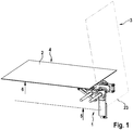
- FIG. 1 shows the device 1 with the plate-shaped element 2.
- the plate-shaped element 2 is initially in a first position 3, for example, a magazine. In the first position 3, the plate-shaped elements 2 are arranged approximately vertically.
- the device 1 removes the plate-shaped elements 2 individually from the first position 3 and conveys them to a second position 4. In this case, both a rotation and a lifting of the plate-shaped elements 2.
- In the first position 3 is a lower edge 23 of the plate-shaped element. 2 at a first height 5.
- the lower edge 23, in particular the entire plate-shaped element 2 lies at a second height 6.
- the second height 6 is higher than the first height 5.
- FIG. 2 shows the device 1 in detail.
- the device 1 is in a position for receiving the plate-shaped elements 2 from the first position 3.
- In FIG. 2 is an angle ⁇ of about 10 ° drawn by which the plate-shaped elements in the first position 3 are inclined to the device 1 out.
- the device 1 comprises a drive 7.
- the drive 7 drives a shaft 8.
- a carrier device 16 is provided on this support device 16, a holding device 9 is mounted.
- the holding device 9 is linearly movable relative to the carrier device 16 by means of a linear guide 17.
- a plurality of suction cups 10 are arranged at the holding device 9 .
- the suckers 10 serve to hold the plate-shaped elements 2.
- a first lever 11 is arranged rotationally fixed.
- the first lever 11 is rotatably connected to a second lever 12 and to a third lever 13.
- the second lever 12 is further rotatably connected to the carrier device 16.
- the third lever 13 is rotatably connected to a fourth lever 14.
- the fourth lever 14 is rotatably mounted about a fixed point 18.
- the fixed point 18 is fixed relative to the shaft 8. Furthermore, the fourth lever 14 is rotatably connected to the support device 16.
- the connection between the first lever 11 and the second lever 12 is referred to as the first connection point 19.
- the third lever 13 is at a second connection point 20 connected to the first lever 11.
- the shaft 8 is arranged between the first connection point 19 and the second connection point 20, so that when the shaft 8 is rotated the first connection point 19 is lowered, for example, and at the same time the second connection point 20 is raised.
- the third lever 13 is connected at one end to the first lever 11. At the other end of the third lever 13 is a third connection point 21 as a connection between the third lever 13 and the fourth lever 14.
- the fourth lever 14 is connected to the carrier device 16 at a fourth connection point 22.
- the fixed point 18 is arranged between the third attachment point 21 and the fourth attachment point 22.
- the shaft 8 is arranged between the first and second connection point 19, 20.
- the fixed point 18 is arranged between the third and fourth connection point 21, 22.
- the arrangement of an element between two connection points does not mean that this element, for example the shaft 8 or the fixed point 18, must lie exactly on a line between the two connection points.
- a first angle ⁇ between an imaginary line from the shaft 8 to the first attachment point 19 and an imaginary line from the shaft 8 to the second attachment point 20 is greater than 90 °.
- a second angle ⁇ between an imaginary line from the third connection point 21 to the fixed point 18 and an imaginary line from the fourth connection point 22 to the fixed point 18 is preferably greater than 90 °.
- a fifth lever 15 is provided.
- the fifth lever 15 is rotatably connected at one end to the holding device 9.
- the other end of the fifth lever 15 is rotatably connected to the third lever 13.
- FIG. 3 shows the device 1 in an intermediate position, between the first position 3 and the second position 4th
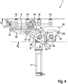
- FIG. 4 shows the device 1 at the second position 4th
Landscapes
- Engineering & Computer Science (AREA)
- Mechanical Engineering (AREA)
- Robotics (AREA)
- Sheets, Magazines, And Separation Thereof (AREA)
- Paper (AREA)
Description
- Die vorliegende Erfindung betrifft eine Vorrichtung zum Entnehmen von plattenförmigen Elementen. Insbesondere dient die Vorrichtung zum Entnehmen von Zuschnitt aus Vollpappe oder Wellpappe. Die plattenförmigen Elemente werden dabei aus einem Magazin entnommen und zur weiteren Verarbeitung abgelegt.
- Die Druckschrift
US 2001/0023227 A1 zeigt eine vorbekannte Vorrichtung zum Entnehmen von Pappenzuschnitten. Die Zuschnitte werden dabei aus der vertikalen Stellung aufgenommen, nach oben angehoben und dabei in eine horizontale Lage gedreht. Die vorbekannte Anordnung ist komplex aufgebaut. -
WO2011/015610 A1 offenbart eine Vorrichtung gemäß dem Oberbegriff des Anspruchs 1. - Die erfindungsgemäße Vorrichtung mit den Merkmalen des Anspruchs 1 ermöglicht ein Entnehmen von plattenförmigen Elementen, insbesondere von Pappenzuschnitten, wobei die Vorrichtung nur einen Antrieb benötigt und somit einfach herstellbar ist und wartungsarm betrieben werden kann. Die erfindungsgemäße Vorrichtung ermöglicht es, vertikal stehende plattenförmige Elemente aufzunehmen und in einer horizontalen Lage wieder abzulegen. Die plattenförmigen Elemente können dabei auf einem Niveau abgelegt werden, das höher liegt als eine Unterkante der plattenförmigen Elemente beim Aufnehmen. Durch die erfindungsgemäße Anordnung der unterschiedlichen Hebel ist der gesamte Bewegungsablauf mit nur einem Antrieb realisierbar. Das Entnehmen der plattenförmigen Elemente und das Drehen in die horizontale Lage erfolgt ohne einer Berührung der noch im Magazin befindlichen plattenförmigen Elemente. Durch die relativ hohe Ablageposition ergibt sich eine ergonomisch günstige Lage für die weitere Verarbeitung. All diese Vorteile werden erreicht durch die erfindungsgemäße Vorrichtung zum Entnehmen von plattenförmigen Elementen, umfassend eine Trägervorrichtung und eine auf der Trägervorrichtung angeordnete Haltevorrichtung zum Halten des plattenförmigen Elementes. Des Weiteren ist ein Antrieb mit einer angetriebenen Welle vorgesehen. Auf der angetriebenen Welle ist ein erster Hebel drehfest angeordnet. Mit dem ersten Hebel und mit der Trägervorrichtung ist ein zweiter Hebel drehbar verbunden. Ein vierter Hebel ist um einen Fixpunkt drehbar angeordnet. Der vierte Hebel ist mit der Trägervorrichtung drehbar verbunden. Des Weiteren ist ein dritter Hebel vorgesehen. Der dritte Hebel ist drehbar mit dem ersten Hebel und drehbar mit dem vierten Hebel verbunden. Lediglich durch die Rotation der angetriebenen Welle können die Hebel in Bewegung gesetzt werden. Durch die erfindungsgemäße Anordnung der Hebel bewegt sich die Trägervorrichtung samt der Haltevorrichtung aus der vertikalen Lage in die horizontale Lage. Dabei erfolgt ein Anheben des aufgenommenen plattenförmigen Elementes, so dass die Unterkante des plattenförmigen Elementes in seiner Endposition höher liegt als in der Ausgangsposition. Die erfindungsgemäße Vorrichtung wird insbesondere zum Entnehmen von Pappenzuschnitten aus einem Magazin verwendet.
- Die Unteransprüche zeigen bevorzugte Weiterbildungen der Erfindung.
- Bevorzugt ist vorgesehen, dass die Haltevorrichtung zumindest einen Greifer und/oder zumindest einen Sauger umfasst. Mit dem Greifer oder Sauger kann das plattenförmige Element an der Haltevorrichtung fixiert werden.
- Die drehbaren Verbindungen zwischen den einzelnen Elementen werden als "Anbindungspunkte" bezeichnet. Der zweite Hebel ist an einem ersten Anbindungspunkt mit dem ersten Hebel verbunden. Der dritte Hebel ist an einem zweiten Anbindungspunkt mit dem ersten Hebel verbunden. Bevorzugt ist vorgesehen, dass die Welle zwischen dem ersten und zweiten Anbindungspunkt angeordnet ist. So wird bei einer Rotation der Welle der erste Anbindungspunkt beispielsweise abgesenkt und gleichzeitig der zweite Anbindungspunkt angehoben.
- Des Weiteren ist vorgesehen, dass der dritten Hebel an einem dritten Anbindungspunkt mit dem vierten Hebel verbunden ist. Die Trägervorrichtung ist an einem vierten Anbindungspunkt mit dem vierten Hebel verbunden. Der Fixpunkt ist zwischen dem dritten und vierten Anbindungspunkt angeordnet.
- Die Anordnung eines Elementes zwischen zwei Anbindungspunkten bedeutet nicht, dass dieses Element, beispielsweise die Welle oder der Fixpunkt, exakt auf einer Linie zwischen den beiden Anbindungspunkten liegen muss. Letztendlich ist es ausreichend, dass ein Winkel zwischen einer imaginären Linie von der Welle zum ersten Anbindungspunkt und einer imaginären Linie von der Welle zum zweiten Anbindungspunkt größer 90° ist. Ebenso ist bevorzugt der Winkel zwischen einer imaginären Linie vom dritten Anbindungspunkt zum Fixpunkt und einer imaginären Linie vom vierten Anbindungspunkt zum Fixpunkt größer 90°.
- In einer bevorzugten Variante ist ein fünfter Hebel vorgesehen. Der fünfte Hebel ist drehbar mit dem dritten Hebel und drehbar mit der Haltevorrichtung verbunden. Die Haltevorrichtung ist dabei auf der Trägervorrichtung linearbeweglich geführt. Mittels des fünften Hebels wird die Haltevorrichtung gegenüber der Trägervorrichtung linear bewegt, so dass ein Anheben des plattenförmigen Elementes erfolgt. Dabei ist bevorzugt vorgesehen, dass der fünfte Hebel zwischen dem zweiten und dritten Anbindungspunkt mit dem dritten Hebel verbunden ist.
- Alternativ zur Verwendung des fünften Hebels ist es auch möglich, die Haltevorrichtung fest mit der Trägervorrichtung zu verbinden. Dadurch vereinfacht sich der Aufbau. Bei dieser Variante muss jedoch beachtet werden, dass das plattenförmige Element nicht so weit angehoben wird, wie bei der Verwendung des fünften Hebels.
- Die Drehachsen der Welle und aller verwendeter Hebel sind bevorzugt parallel zueinander, und vorzugsweise horizontal, ausgerichtet.
- Der Fixpunkt ist insbesondere fix gegenüber der angetriebenen Welle.
- Die gesamte Vorrichtung steht bevorzugt auf einem Sockel. Bevorzugt ist der Antrieb in diesen Sockel integriert.
- Des Weiteren ist bevorzugt vorgesehen, dass die Hebel der Vorrichtung dazu ausgebildet sind, um das plattenförmige Element aus einer ersten Position (auch: Ausgangsposition oder Magazin) zu entnehmen und in einer zweiten Position abzulegen, wobei das plattenförmige Element in der ersten Position vertikal steht und wobei das plattenförmige Element in der zweiten Position horizontal liegt. Die vertikale und horizontale Lage sind jeweils mit einer Abweichung bis zu ± 20° zu sehen. Vorzugsweise sind die plattenförmigen Elemente in der ersten Position um 10° ± 5° zur Vorrichtung hin geneigt. Die Lage des plattenförmigen Elementes, insbesondere die Lage der Unterkante, in der zweiten Position ist höher als die Lage der Unterkante des plattenförmigen Elementes in der ersten Position.
- Nachfolgend wird ein Ausführungsbeispiel der Erfindung unter Bezugnahme auf die begleitende Zeichnung im Detail beschrieben. Dabei zeigen:
-
Figur 1 eine isometrische Ansicht einer erfindungsgemäßen Vorrichtung mit einem plattenförmigen Element gemäß einem Ausführungsbeispiel, -
Figur 2 einen ersten Zustand der erfindungsgemäßen Vorrichtung gemäß dem Ausführungsbeispiel, -
Figur 3 einen zweiten Zustand der erfindungsgemäßen Vorrichtung gemäß dem Ausführungsbeispiel, und -
Figur 4 einen dritten Zustand der erfindungsgemäßen Vorrichtung gemäß dem Ausführungsbeispiel. - Im Folgenden wird anhand der
Figuren 1 bis 4 eine Vorrichtung 1 zum Entnehmen von plattenförmigen Elementen 2, ausgebildet als Pappenzuschnitte, gezeigt. -
Figur 1 zeigt die Vorrichtung 1 mit dem plattenförmigen Element 2. Das plattenförmige Element 2 befindet sich zunächst in einer ersten Position 3, beispielsweise einem Magazin. In der ersten Position 3 sind die plattenförmigen Elemente 2 annähernd vertikal angeordnet. Die Vorrichtung 1 entnimmt die plattenförmigen Elemente 2 einzeln aus der ersten Position 3 und befördert sie zu einer zweiten Position 4. Dabei erfolgt sowohl ein Drehen als auch ein Anheben der plattenförmigen Elemente 2. In der ersten Position 3 liegt eine Unterkante 23 des plattenförmigen Elementes 2 auf einer ersten Höhe 5. In der zweiten Position 4 liegt die Unterkante 23, insbesondere das gesamte plattenförmige Element 2, auf einer zweiten Höhe 6. Die zweite Höhe 6 ist höher als die erste Höhe 5. -
Figur 2 zeigt die Vorrichtung 1 im Detail. Die Vorrichtung 1 befindet sich dabei in einer Stellung zum Aufnehmen der plattenförmigen Elemente 2 aus der ersten Position 3. InFigur 2 ist ein Winkel γ von ca. 10° eingezeichnet, um den die plattenförmigen Elemente in der ersten Position 3 zur Vorrichtung 1 hin geneigt sind. - Die Vorrichtung 1 umfasst einen Antrieb 7. Der Antrieb 7 treibt eine Welle 8 an. Des Weiteren ist eine Trägervorrichtung 16 vorgesehen. Auf dieser Trägervorrichtung 16 ist eine Haltevorrichtung 9 montiert. Die Haltevorrichtung 9 ist dabei mittels einer Linearführung 17 linearbeweglich gegenüber der Trägervorrichtung 16. An der Haltevorrichtung 9 sind mehrere Sauger 10 angeordnet. Die Sauger 10 dienen zum Halten der plattenförmigen Elemente 2.
- Auf der Welle 8 ist ein erster Hebel 11 drehfest angeordnet. Der erste Hebel 11 ist mit einem zweiten Hebel 12 und mit einem dritten Hebel 13 drehbar verbunden. Der zweite Hebel 12 ist des Weiteren mit der Trägervorrichtung 16 drehbar verbunden. Der dritte Hebel 13 ist mit einem vierten Hebel 14 drehbar verbunden.
- Der vierte Hebel 14 ist um einen Fixpunkt 18 drehbar gelagert. Der Fixpunkt 18 ist dabei fix gegenüber der Welle 8. Des Weiteren ist der vierte Hebel 14 drehbar mit der Trägervorrichtung 16 verbunden.
- Die Verbindung zwischen dem ersten Hebel 11 und dem zweiten Hebel 12 wird als erster Anbindungspunkt 19 bezeichnet. Der dritte Hebel 13 ist an einem zweiten Anbindungspunkt 20 mit dem ersten Hebel 11 verbunden. Die Welle 8 ist zwischen dem ersten Anbindungspunkt 19 und dem zweiten Anbindungspunkt 20 angeordnet, so dass bei einem Drehen der Welle 8 der erste Anbindungspunkt 19 beispielsweise abgesenkt und gleichzeitig der zweite Anbindungspunkt 20 angehoben wird.
- Der dritte Hebel 13 ist mit einem Ende mit dem ersten Hebel 11 verbunden. An dem anderen Ende des dritten Hebels 13 befindet sich ein dritter Anbindungspunkt 21 als Verbindung zwischen dem dritten Hebel 13 und dem vierten Hebel 14. Der vierte Hebel 14 ist an einem vierten Anbindungspunkt 22 mit der Trägervorrichtung 16 verbunden. Der Fixpunkt 18 ist zwischen dem dritten Anbindungspunkt 21 und dem vierten Anbindungspunkt 22 angeordnet.
- Die Welle 8 ist zwischen dem ersten und zweiten Anbindungspunkt 19, 20 angeordnet ist. Der Fixpunkt 18 ist zwischen dem dritten und vierten Anbindungspunkt 21, 22 angeordnet. Die Anordnung eines Elementes zwischen zwei Anbindungspunkten bedeutet nicht, dass dieses Element, beispielsweise die Welle 8 oder der Fixpunkt 18, exakt auf einer Linie zwischen den beiden Anbindungspunkten liegen muss. Letztendlich ist es ausreichend, dass ein erster Winkel α zwischen einer imaginären Linie von der Welle 8 zum ersten Anbindungspunkt 19 und einer imaginären Linie von der Welle 8 zum zweiten Anbindungspunkt 20 größer 90° ist. Ebenso ist bevorzugt ein zweiter Winkel β zwischen einer imaginären Linie vom dritten Anbindungspunkt 21 zum Fixpunkt 18 und einer imaginären Linie vom vierten Anbindungspunkt 22 zum Fixpunkt 18 größer 90°.
- Des Weiteren ist ein fünfter Hebel 15 vorgesehen. Der fünfte Hebel 15 ist mit einem Ende drehbar mit der Haltevorrichtung 9 verbunden. Das andere Ende des fünften Hebels 15 ist drehbar mit dem dritten Hebel 13 verbunden.
-
Figur 3 zeigt die Vorrichtung 1 in einer Zwischenstellung, zwischen der ersten Position 3 und der zweiten Position 4. -
Figur 4 zeigt die Vorrichtung 1 an der zweiten Position 4. - Ausgehend von der Stellung in
Figur 2 wird die Welle 8 gegen den Uhrzeigersinn gedreht. Dadurch zieht der zweite Hebel 12 den oberen Teil der Trägervorrichtung 16 nach links. Gleichzeitig wird der dritte Hebel 13 und der vierte Hebel 14 im Uhrzeigersinn gedreht. Dadurch bewegt sich der untere Teil der Trägervorrichtung 16 nach links. Somit ergibt sich für die Trägervorrichtung 16 und die darauf mit der Linearführung angeordnete Haltevorrichtung 9 eine Bewegung nach links. Dadurch ist es möglich, dass in der ersten Position 3 ein einzelnes plattenförmiges Element 2 von den verbleibenden plattenförmigen Elementen im Magazin weggehoben werden kann. - Durch eine weitere Drehung der Welle 8 gegen den Uhrzeigersinn wird der obere Teil der Trägervorrichtung 16 nach links unten gezogen. Die Trägervorrichtung 16 kippt dabei gegen den Uhrzeigersinn ab. Dies zeigt die Darstellung in
Figur 3 . Gleichzeitig wird der dritte Hebel 13 nach links angehoben. Über den fünften Hebel 15 wird die Haltevorrichtung 9 nach links oben verschoben. Dadurch bewegt sich die Unterkante 23 auch nach oben links und berührt beim Abkippen nicht die noch im Magazin stehenden plattenförmigen Elemente. - Wird die angetriebene Welle 8 weiter gegen den Uhrzeigersinn gedreht, bewegt sich der erste Hebel 11 weiter über die gestreckte Lage des ersten Hebels 11 und des dritten Hebels 13 hinweg. Der vierte Hebel 14 bewegt sich gegen den Uhrzeigersinn. Damit wird der untere Teil der Trägervorrichtung 16 angehoben, während der oberen Teil der Trägervorrichtung 16 nach links unten abkippt, bis die horizontale Lage gemäß der zweiten Position 4 erreicht ist. Dies zeigt die Darstellung in
Figur 4 . - In der beschriebenen Ausführungsform handelt es sich um ein sieben-gliedriges Koppelgetriebe mit nur einem einzigen Antrieb.
- Zur Vereinfachung der Kinematik kann auf den fünften Hebel 15 und auf die Linearführung 17 verzichtet werden. Dadurch entsteht ein fünf-gliedriges Koppelgetriebe mit nur einem Antrieb. Dabei reduziert sich die zweite Höhe 6 etwas, wobei sich der Aufbau der Vorrichtung 1 vereinfacht.
Claims (9)
- Vorrichtung (1) zum Entnehmen von plattenförmigen Elementen (2), insbesondere von Pappenzuschnitt, umfassend- eine Trägervorrichtung (16),- eine auf der Trägervorrichtung (16) angeordnete Haltevorrichtung (9) zum Halten des plattenförmigen Elementes (2),- einen Antrieb (7) mit einer angetriebenen Welle (8),- einen drehfest auf der Welle (8) angeordneten ersten Hebel (11),gekennzeichnet durch- einen drehbar mit dem ersten Hebel (11) und drehbar mit der Trägervorrichtung (16) verbundenen zweiten Hebel (12),- einen um einem Fixpunkt (18) drehbar angeordneten vierten Hebel (14), wobei der vierte Hebel (14) drehbar mit der Trägervorrichtung (16) verbunden ist, und- einen drehbar mit dem ersten Hebel (11) und drehbar mit dem vierten Hebel (14) verbundenen dritten Hebel (13).
- Vorrichtung nach Anspruch 1, dadurch gekennzeichnet, dass die Haltevorrichtung (9) zumindest einen Greifer und/oder zumindest einen Sauger (10) zum Halten des plattenförmigen Elementes (2) umfasst.
- Vorrichtung nach einem der vorhergehenden Ansprüche, dadurch gekennzeichnet, dass der zweite Hebel (12) an einem ersten Anbindungspunkt (19) mit dem ersten Hebel (11) verbunden ist, und der dritte Hebel (13) an einem zweiten Anbindungspunkt (20) mit dem ersten Hebel (11) verbunden ist, wobei die Welle (8) zwischen dem ersten und zweiten Anbindungspunkt (19, 20) angeordnet ist.
- Vorrichtung nach einem der vorhergehenden Ansprüche, dadurch gekennzeichnet, dass der dritte Hebel (13) an einem dritten Anbindungspunkt (21) mit dem vierten Hebel (14) verbunden ist, und die Trägervorrichtung (16) an einem vierten Anbindungspunkt (22) mit dem vierten Hebel (14) verbunden ist, wobei der Fixpunkt (18) zwischen dem dritten und vierten Anbindungspunkt (21, 22) angeordnet ist.
- Vorrichtung nach einem der vorhergehenden Ansprüche, gekennzeichnet durch einen drehbar mit dem dritten Hebel (13) und drehbar mit der Haltevorrichtung (9) verbundenen fünften Hebel (15), wobei die Haltevorrichtung (9) auf der Trägervorrichtung (16) linearbeweglich geführt ist.
- Vorrichtung nach Anspruch 5, dadurch gekennzeichnet, dass der fünfte Hebel (15) zwischen dem zweiten und dritten Anbindungspunkt (20, 21) mit dem dritten Hebel (13) verbunden ist.
- Vorrichtung nach einem der Ansprüche 1 bis 4, dadurch gekennzeichnet, dass die Haltevorrichtung (9) fest mit der Trägervorrichtung (16) verbunden ist.
- Vorrichtung nach einem der vorhergehenden Ansprüche, dadurch gekennzeichnet, dass die Drehachsen der Welle (8) und aller Hebel (11-15) parallel zueinander, und vorzugsweise horizontal, ausgerichtet sind.
- Vorrichtung nach einem der vorhergehenden Ansprüche, dadurch gekennzeichnet, dass die Hebel (11-15) der Vorrichtung (1) dazu ausgebildet sind, um das plattenförmige Element (2) aus einer ersten Position (3) zu entnehmen und in einer zweiten Position (4) abzulegen, wobei das plattenförmige Element (2) in der ersten Position (3) mit einer Abweichung von +/- 20° vertikal steht, wobei das plattenförmige Element (2) in der zweiten Position (4) mit einer Abweichung von +/- 20° horizontal liegt, und wobei die Lage des plattenförmigen Elementes (2) in der zweiten Position (4) höher ist als eine Unterkante (23) des plattenförmigen Elementes (2) in der ersten Position (3).
Applications Claiming Priority (2)
| Application Number | Priority Date | Filing Date | Title |
|---|---|---|---|
| DE102013200146.0A DE102013200146A1 (de) | 2013-01-08 | 2013-01-08 | Vorrichtung zum Entnehmen von plattenförmigen Elementen, insbesondere vonPappenzuschnitt |
| PCT/EP2013/074814 WO2014108243A1 (de) | 2013-01-08 | 2013-11-27 | Vorrichtung zum entnehmen von plattenförmigen elementen, insbesondere von pappenzuschnitt |
Publications (2)
| Publication Number | Publication Date |
|---|---|
| EP2943426A1 EP2943426A1 (de) | 2015-11-18 |
| EP2943426B1 true EP2943426B1 (de) | 2017-01-11 |
Family
ID=49724553
Family Applications (1)
| Application Number | Title | Priority Date | Filing Date |
|---|---|---|---|
| EP13801502.9A Active EP2943426B1 (de) | 2013-01-08 | 2013-11-27 | Vorrichtung zum entnehmen von plattenförmigen elementen, insbesondere von pappenzuschnitt |
Country Status (5)
| Country | Link |
|---|---|
| US (1) | US9616575B2 (de) |
| EP (1) | EP2943426B1 (de) |
| DE (1) | DE102013200146A1 (de) |
| ES (1) | ES2621959T3 (de) |
| WO (1) | WO2014108243A1 (de) |
Families Citing this family (4)
| Publication number | Priority date | Publication date | Assignee | Title |
|---|---|---|---|---|
| EP2952303B1 (de) * | 2014-06-05 | 2017-10-11 | J. Schmalz GmbH | Verfahren zur handhabung von flexiblen mattenartigen werkstücken |
| CN105923388B (zh) * | 2016-06-14 | 2018-04-13 | 江苏科技大学 | 一种模切机自动下料装置及方法 |
| EP4025528A2 (de) * | 2019-09-05 | 2022-07-13 | Interroll Holding AG | Transportbehälter für eine sortiervorrichtung |
| CN113291800B (zh) * | 2021-06-17 | 2022-07-19 | 南通大学 | 一种焊料自动上料装置 |
Family Cites Families (14)
| Publication number | Priority date | Publication date | Assignee | Title |
|---|---|---|---|---|
| US3053529A (en) * | 1960-02-01 | 1962-09-11 | Memco Machinery Corp | Blank feeding apparatus for box erecting machine |
| SE375724B (de) * | 1973-08-23 | 1975-04-28 | Volvo Ab | |
| US4093083A (en) * | 1975-04-17 | 1978-06-06 | Spiegelglaswerke Germania, Zweigniederlassung Der Glaceries De Saint.Roch S.A. | Apparatus for stacking and unstacking sheet material, more particularly glass sheets |
| US4018342A (en) * | 1976-02-27 | 1977-04-19 | Owens-Illinois, Inc. | Article transfer apparatus |
| US4494537A (en) * | 1982-06-08 | 1985-01-22 | Gottlieb Mark P | Breathing apparatus for supplying fluid to a user on demand |
| SE469879B (sv) * | 1988-09-28 | 1993-10-04 | Volvo Ab | Anordning för överföring av föremål |
| US5094495A (en) * | 1990-01-10 | 1992-03-10 | Littell Edmund R | Mechanism for lifting and orienting an object |
| IT237182Y1 (it) * | 1995-09-29 | 2000-09-05 | Francesco Canziani | Disimpilatore per piccoli oggetti piatti quali in particolareaudio/videocassette o simili |
| IT1321149B1 (it) | 2000-03-15 | 2003-12-30 | Baumer Srl | Metodo e sistema per trasferire fustellati in successione singola. |
| ES1048690Y (es) * | 2001-02-01 | 2002-02-01 | Vivas Leon Benmayor | Cargador descargador de circuitos impresos. |
| CA2435585A1 (en) * | 2002-08-27 | 2004-02-27 | Sig Technology Ltd. | Separating arrangement for a cartoning machine |
| ITVI20040277A1 (it) * | 2004-12-03 | 2005-03-03 | Giorgio Bergamini | Apparato per la manipolazione di carichi |
| DE102009036700A1 (de) * | 2009-08-07 | 2011-03-17 | Bottero Gmbh | Vorrichtung zum Übergeben von Plattenmaterial in einer Fertigungsanlage |
| IT1404200B1 (it) * | 2011-02-23 | 2013-11-15 | Samec S P A | Dispositivo per il caricamento di elementi piani, in particolare pannelli, su una macchina utensile. |
-
2013
- 2013-01-08 DE DE102013200146.0A patent/DE102013200146A1/de not_active Withdrawn
- 2013-11-27 US US14/759,439 patent/US9616575B2/en not_active Expired - Fee Related
- 2013-11-27 WO PCT/EP2013/074814 patent/WO2014108243A1/de not_active Ceased
- 2013-11-27 EP EP13801502.9A patent/EP2943426B1/de active Active
- 2013-11-27 ES ES13801502.9T patent/ES2621959T3/es active Active
Non-Patent Citations (1)
| Title |
|---|
| None * |
Also Published As
| Publication number | Publication date |
|---|---|
| EP2943426A1 (de) | 2015-11-18 |
| ES2621959T3 (es) | 2017-07-05 |
| DE102013200146A1 (de) | 2014-07-10 |
| US9616575B2 (en) | 2017-04-11 |
| WO2014108243A1 (de) | 2014-07-17 |
| US20150352723A1 (en) | 2015-12-10 |
Similar Documents
| Publication | Publication Date | Title |
|---|---|---|
| DE102013009340B4 (de) | Einrichtung und Verfahren zum Ein- und Auslagern von stapelbaren Behältern | |
| DE1948425C3 (de) | Ein- und Auslagervorrichtung für Stapelplatten an frei wählbaren Stellen des Stapels | |
| EP2982624B1 (de) | Haltevorrichtung und Lagersystem für Behälterstapel | |
| DE69415429T2 (de) | Vorrichtung zur Einlagerung und Entnahme für eine Biegepresse | |
| DE202008004809U1 (de) | Höhenverstellbarer Geräteständer | |
| DE102014011235A1 (de) | Vorrichtung und Verfahren zum Überwinden von Treppen und ähnliche Hindernissen für Haushaltsroboter wie Staubsauger oder andere autonome Geräte | |
| DE112020001748B4 (de) | Haltevorrichtung mit einem ersten und einem zweiten haltemechanismus und hiermit versehener roboter | |
| DE102015102693B4 (de) | Behältertragevorrichtung für eine Roboterhand | |
| DE69938260T2 (de) | Einheit zum Halten eines Werkstückes mittels Vakuum und Vakuumkopf | |
| DE102015210842B3 (de) | Vorrichtung und Verfahren zum Greifen, Vereinzeln, Transportieren und/oder Ablegen von verschlossenen und/oder unverschlossenen Petrischalen | |
| DE202020102769U1 (de) | Verpackungsautomat für Karten | |
| WO2014108243A1 (de) | Vorrichtung zum entnehmen von plattenförmigen elementen, insbesondere von pappenzuschnitt | |
| DE102010023595A1 (de) | Behälter mit höhenverstellbarem Boden | |
| DE202015106824U1 (de) | Transportbox | |
| EP3450985A1 (de) | Mikroplatten-bearbeitungsgerät | |
| EP1836291A1 (de) | Automatische lagervorrichtung und klimaschrank für laborgüter | |
| EP3385177A1 (de) | Verpackungsmaschine mit neigbarer werkzeugschublade | |
| DE102013114041A1 (de) | Probenmanipulationseinrichtung | |
| EP2368763A1 (de) | Ladebodeneinrichtung für den Laderaum eines Kraftwagens | |
| DE19711683C2 (de) | IC-Baustein-Montage/Demontage-System sowie Montage/Demontage-Kopf für ein derartiges IC-Baustein-Montage-/Demontage-System | |
| DE102014222423A1 (de) | Spannvorrichtung | |
| DE102015002502A1 (de) | Vorrichtung zum Wenden von formstabilen Behältern | |
| DE2045507A1 (de) | Gerat zum Einsetzen von Zeigern von Uhren oder anderen Messgeraten | |
| DE102007049944A1 (de) | Flachbildschirm-Haltevorrichtung | |
| DE102019200050A1 (de) | Luftleitvorrichtung |
Legal Events
| Date | Code | Title | Description |
|---|---|---|---|
| PUAI | Public reference made under article 153(3) epc to a published international application that has entered the european phase |
Free format text: ORIGINAL CODE: 0009012 |
|
| 17P | Request for examination filed |
Effective date: 20150810 |
|
| AK | Designated contracting states |
Kind code of ref document: A1 Designated state(s): AL AT BE BG CH CY CZ DE DK EE ES FI FR GB GR HR HU IE IS IT LI LT LU LV MC MK MT NL NO PL PT RO RS SE SI SK SM TR |
|
| AX | Request for extension of the european patent |
Extension state: BA ME |
|
| DAX | Request for extension of the european patent (deleted) | ||
| GRAP | Despatch of communication of intention to grant a patent |
Free format text: ORIGINAL CODE: EPIDOSNIGR1 |
|
| INTG | Intention to grant announced |
Effective date: 20160913 |
|
| GRAS | Grant fee paid |
Free format text: ORIGINAL CODE: EPIDOSNIGR3 |
|
| GRAA | (expected) grant |
Free format text: ORIGINAL CODE: 0009210 |
|
| AK | Designated contracting states |
Kind code of ref document: B1 Designated state(s): AL AT BE BG CH CY CZ DE DK EE ES FI FR GB GR HR HU IE IS IT LI LT LU LV MC MK MT NL NO PL PT RO RS SE SI SK SM TR |
|
| REG | Reference to a national code |
Ref country code: GB Ref legal event code: FG4D Free format text: NOT ENGLISH |
|
| REG | Reference to a national code |
Ref country code: CH Ref legal event code: EP |
|
| REG | Reference to a national code |
Ref country code: AT Ref legal event code: REF Ref document number: 861056 Country of ref document: AT Kind code of ref document: T Effective date: 20170115 |
|
| REG | Reference to a national code |
Ref country code: IE Ref legal event code: FG4D Free format text: LANGUAGE OF EP DOCUMENT: GERMAN |
|
| REG | Reference to a national code |
Ref country code: DE Ref legal event code: R096 Ref document number: 502013006111 Country of ref document: DE |
|
| REG | Reference to a national code |
Ref country code: NL Ref legal event code: FP |
|
| REG | Reference to a national code |
Ref country code: LT Ref legal event code: MG4D |
|
| REG | Reference to a national code |
Ref country code: ES Ref legal event code: FG2A Ref document number: 2621959 Country of ref document: ES Kind code of ref document: T3 Effective date: 20170705 |
|
| PG25 | Lapsed in a contracting state [announced via postgrant information from national office to epo] |
Ref country code: HR Free format text: LAPSE BECAUSE OF FAILURE TO SUBMIT A TRANSLATION OF THE DESCRIPTION OR TO PAY THE FEE WITHIN THE PRESCRIBED TIME-LIMIT Effective date: 20170111 Ref country code: NO Free format text: LAPSE BECAUSE OF FAILURE TO SUBMIT A TRANSLATION OF THE DESCRIPTION OR TO PAY THE FEE WITHIN THE PRESCRIBED TIME-LIMIT Effective date: 20170411 Ref country code: FI Free format text: LAPSE BECAUSE OF FAILURE TO SUBMIT A TRANSLATION OF THE DESCRIPTION OR TO PAY THE FEE WITHIN THE PRESCRIBED TIME-LIMIT Effective date: 20170111 Ref country code: LT Free format text: LAPSE BECAUSE OF FAILURE TO SUBMIT A TRANSLATION OF THE DESCRIPTION OR TO PAY THE FEE WITHIN THE PRESCRIBED TIME-LIMIT Effective date: 20170111 Ref country code: IS Free format text: LAPSE BECAUSE OF FAILURE TO SUBMIT A TRANSLATION OF THE DESCRIPTION OR TO PAY THE FEE WITHIN THE PRESCRIBED TIME-LIMIT Effective date: 20170511 Ref country code: GR Free format text: LAPSE BECAUSE OF FAILURE TO SUBMIT A TRANSLATION OF THE DESCRIPTION OR TO PAY THE FEE WITHIN THE PRESCRIBED TIME-LIMIT Effective date: 20170412 |
|
| PG25 | Lapsed in a contracting state [announced via postgrant information from national office to epo] |
Ref country code: BG Free format text: LAPSE BECAUSE OF FAILURE TO SUBMIT A TRANSLATION OF THE DESCRIPTION OR TO PAY THE FEE WITHIN THE PRESCRIBED TIME-LIMIT Effective date: 20170411 Ref country code: SE Free format text: LAPSE BECAUSE OF FAILURE TO SUBMIT A TRANSLATION OF THE DESCRIPTION OR TO PAY THE FEE WITHIN THE PRESCRIBED TIME-LIMIT Effective date: 20170111 Ref country code: RS Free format text: LAPSE BECAUSE OF FAILURE TO SUBMIT A TRANSLATION OF THE DESCRIPTION OR TO PAY THE FEE WITHIN THE PRESCRIBED TIME-LIMIT Effective date: 20170111 Ref country code: PL Free format text: LAPSE BECAUSE OF FAILURE TO SUBMIT A TRANSLATION OF THE DESCRIPTION OR TO PAY THE FEE WITHIN THE PRESCRIBED TIME-LIMIT Effective date: 20170111 Ref country code: PT Free format text: LAPSE BECAUSE OF FAILURE TO SUBMIT A TRANSLATION OF THE DESCRIPTION OR TO PAY THE FEE WITHIN THE PRESCRIBED TIME-LIMIT Effective date: 20170511 Ref country code: LV Free format text: LAPSE BECAUSE OF FAILURE TO SUBMIT A TRANSLATION OF THE DESCRIPTION OR TO PAY THE FEE WITHIN THE PRESCRIBED TIME-LIMIT Effective date: 20170111 |
|
| REG | Reference to a national code |
Ref country code: DE Ref legal event code: R097 Ref document number: 502013006111 Country of ref document: DE |
|
| PG25 | Lapsed in a contracting state [announced via postgrant information from national office to epo] |
Ref country code: CZ Free format text: LAPSE BECAUSE OF FAILURE TO SUBMIT A TRANSLATION OF THE DESCRIPTION OR TO PAY THE FEE WITHIN THE PRESCRIBED TIME-LIMIT Effective date: 20170111 Ref country code: RO Free format text: LAPSE BECAUSE OF FAILURE TO SUBMIT A TRANSLATION OF THE DESCRIPTION OR TO PAY THE FEE WITHIN THE PRESCRIBED TIME-LIMIT Effective date: 20170111 Ref country code: EE Free format text: LAPSE BECAUSE OF FAILURE TO SUBMIT A TRANSLATION OF THE DESCRIPTION OR TO PAY THE FEE WITHIN THE PRESCRIBED TIME-LIMIT Effective date: 20170111 Ref country code: SK Free format text: LAPSE BECAUSE OF FAILURE TO SUBMIT A TRANSLATION OF THE DESCRIPTION OR TO PAY THE FEE WITHIN THE PRESCRIBED TIME-LIMIT Effective date: 20170111 |
|
| PLBE | No opposition filed within time limit |
Free format text: ORIGINAL CODE: 0009261 |
|
| STAA | Information on the status of an ep patent application or granted ep patent |
Free format text: STATUS: NO OPPOSITION FILED WITHIN TIME LIMIT |
|
| REG | Reference to a national code |
Ref country code: FR Ref legal event code: PLFP Year of fee payment: 5 |
|
| PG25 | Lapsed in a contracting state [announced via postgrant information from national office to epo] |
Ref country code: DK Free format text: LAPSE BECAUSE OF FAILURE TO SUBMIT A TRANSLATION OF THE DESCRIPTION OR TO PAY THE FEE WITHIN THE PRESCRIBED TIME-LIMIT Effective date: 20170111 Ref country code: SM Free format text: LAPSE BECAUSE OF FAILURE TO SUBMIT A TRANSLATION OF THE DESCRIPTION OR TO PAY THE FEE WITHIN THE PRESCRIBED TIME-LIMIT Effective date: 20170111 |
|
| 26N | No opposition filed |
Effective date: 20171012 |
|
| PG25 | Lapsed in a contracting state [announced via postgrant information from national office to epo] |
Ref country code: SI Free format text: LAPSE BECAUSE OF FAILURE TO SUBMIT A TRANSLATION OF THE DESCRIPTION OR TO PAY THE FEE WITHIN THE PRESCRIBED TIME-LIMIT Effective date: 20170111 |
|
| PG25 | Lapsed in a contracting state [announced via postgrant information from national office to epo] |
Ref country code: MC Free format text: LAPSE BECAUSE OF FAILURE TO SUBMIT A TRANSLATION OF THE DESCRIPTION OR TO PAY THE FEE WITHIN THE PRESCRIBED TIME-LIMIT Effective date: 20170111 |
|
| GBPC | Gb: european patent ceased through non-payment of renewal fee |
Effective date: 20171127 |
|
| PG25 | Lapsed in a contracting state [announced via postgrant information from national office to epo] |
Ref country code: CH Free format text: LAPSE BECAUSE OF NON-PAYMENT OF DUE FEES Effective date: 20171130 Ref country code: LI Free format text: LAPSE BECAUSE OF NON-PAYMENT OF DUE FEES Effective date: 20171130 |
|
| PG25 | Lapsed in a contracting state [announced via postgrant information from national office to epo] |
Ref country code: LU Free format text: LAPSE BECAUSE OF NON-PAYMENT OF DUE FEES Effective date: 20171127 |
|
| REG | Reference to a national code |
Ref country code: BE Ref legal event code: MM Effective date: 20171130 |
|
| REG | Reference to a national code |
Ref country code: IE Ref legal event code: MM4A |
|
| PG25 | Lapsed in a contracting state [announced via postgrant information from national office to epo] |
Ref country code: MT Free format text: LAPSE BECAUSE OF FAILURE TO SUBMIT A TRANSLATION OF THE DESCRIPTION OR TO PAY THE FEE WITHIN THE PRESCRIBED TIME-LIMIT Effective date: 20170111 |
|
| PG25 | Lapsed in a contracting state [announced via postgrant information from national office to epo] |
Ref country code: IE Free format text: LAPSE BECAUSE OF NON-PAYMENT OF DUE FEES Effective date: 20171127 |
|
| PG25 | Lapsed in a contracting state [announced via postgrant information from national office to epo] |
Ref country code: GB Free format text: LAPSE BECAUSE OF NON-PAYMENT OF DUE FEES Effective date: 20171127 Ref country code: BE Free format text: LAPSE BECAUSE OF NON-PAYMENT OF DUE FEES Effective date: 20171130 |
|
| PG25 | Lapsed in a contracting state [announced via postgrant information from national office to epo] |
Ref country code: HU Free format text: LAPSE BECAUSE OF FAILURE TO SUBMIT A TRANSLATION OF THE DESCRIPTION OR TO PAY THE FEE WITHIN THE PRESCRIBED TIME-LIMIT; INVALID AB INITIO Effective date: 20131127 |
|
| PG25 | Lapsed in a contracting state [announced via postgrant information from national office to epo] |
Ref country code: CY Free format text: LAPSE BECAUSE OF FAILURE TO SUBMIT A TRANSLATION OF THE DESCRIPTION OR TO PAY THE FEE WITHIN THE PRESCRIBED TIME-LIMIT Effective date: 20170111 |
|
| PG25 | Lapsed in a contracting state [announced via postgrant information from national office to epo] |
Ref country code: MK Free format text: LAPSE BECAUSE OF FAILURE TO SUBMIT A TRANSLATION OF THE DESCRIPTION OR TO PAY THE FEE WITHIN THE PRESCRIBED TIME-LIMIT Effective date: 20170111 |
|
| REG | Reference to a national code |
Ref country code: AT Ref legal event code: MM01 Ref document number: 861056 Country of ref document: AT Kind code of ref document: T Effective date: 20181127 |
|
| PG25 | Lapsed in a contracting state [announced via postgrant information from national office to epo] |
Ref country code: AT Free format text: LAPSE BECAUSE OF NON-PAYMENT OF DUE FEES Effective date: 20181127 |
|
| PG25 | Lapsed in a contracting state [announced via postgrant information from national office to epo] |
Ref country code: TR Free format text: LAPSE BECAUSE OF FAILURE TO SUBMIT A TRANSLATION OF THE DESCRIPTION OR TO PAY THE FEE WITHIN THE PRESCRIBED TIME-LIMIT Effective date: 20170111 |
|
| REG | Reference to a national code |
Ref country code: DE Ref legal event code: R082 Ref document number: 502013006111 Country of ref document: DE Representative=s name: DAUB, THOMAS, DIPL.-ING., DE Ref country code: DE Ref legal event code: R081 Ref document number: 502013006111 Country of ref document: DE Owner name: SYNTEGON PACKAGING TECHNOLOGY GMBH, DE Free format text: FORMER OWNER: ROBERT BOSCH GMBH, 70469 STUTTGART, DE |
|
| PG25 | Lapsed in a contracting state [announced via postgrant information from national office to epo] |
Ref country code: AL Free format text: LAPSE BECAUSE OF FAILURE TO SUBMIT A TRANSLATION OF THE DESCRIPTION OR TO PAY THE FEE WITHIN THE PRESCRIBED TIME-LIMIT Effective date: 20170111 |
|
| REG | Reference to a national code |
Ref country code: NL Ref legal event code: PD Owner name: SYNTEGON PACKAGING TECHNOLOGY GMBH; DE Free format text: DETAILS ASSIGNMENT: CHANGE OF OWNER(S), ASSIGNMENT; FORMER OWNER NAME: ROBERT BOSCH GMBH Effective date: 20201120 |
|
| REG | Reference to a national code |
Ref country code: ES Ref legal event code: PC2A Owner name: SYNTEGON PACKAGING TECHNOLOGY GMBH Effective date: 20210308 |
|
| PGFP | Annual fee paid to national office [announced via postgrant information from national office to epo] |
Ref country code: NL Payment date: 20241120 Year of fee payment: 12 |
|
| PGFP | Annual fee paid to national office [announced via postgrant information from national office to epo] |
Ref country code: DE Payment date: 20241119 Year of fee payment: 12 |
|
| PGFP | Annual fee paid to national office [announced via postgrant information from national office to epo] |
Ref country code: FR Payment date: 20241128 Year of fee payment: 12 |
|
| PGFP | Annual fee paid to national office [announced via postgrant information from national office to epo] |
Ref country code: IT Payment date: 20241129 Year of fee payment: 12 Ref country code: ES Payment date: 20241213 Year of fee payment: 12 |
|
| REG | Reference to a national code |
Ref country code: DE Ref legal event code: R082 Ref document number: 502013006111 Country of ref document: DE Representative=s name: DAUB PARTG MBB, DE |
|
| REG | Reference to a national code |
Ref country code: DE Ref legal event code: R119 Ref document number: 502013006111 Country of ref document: DE |
|
| REG | Reference to a national code |
Ref country code: NL Ref legal event code: MM Effective date: 20251201 |