EP2942500A1 - Abgaswärmetauscher mit bypassrohr - Google Patents
Abgaswärmetauscher mit bypassrohr Download PDFInfo
- Publication number
- EP2942500A1 EP2942500A1 EP15163686.7A EP15163686A EP2942500A1 EP 2942500 A1 EP2942500 A1 EP 2942500A1 EP 15163686 A EP15163686 A EP 15163686A EP 2942500 A1 EP2942500 A1 EP 2942500A1
- Authority
- EP
- European Patent Office
- Prior art keywords
- heat exchanger
- bypass
- exhaust gas
- exhaust
- inlet
- Prior art date
- Legal status (The legal status is an assumption and is not a legal conclusion. Google has not performed a legal analysis and makes no representation as to the accuracy of the status listed.)
- Withdrawn
Links
Images


Classifications
-
- F—MECHANICAL ENGINEERING; LIGHTING; HEATING; WEAPONS; BLASTING
- F02—COMBUSTION ENGINES; HOT-GAS OR COMBUSTION-PRODUCT ENGINE PLANTS
- F02M—SUPPLYING COMBUSTION ENGINES IN GENERAL WITH COMBUSTIBLE MIXTURES OR CONSTITUENTS THEREOF
- F02M26/00—Engine-pertinent apparatus for adding exhaust gases to combustion-air, main fuel or fuel-air mixture, e.g. by exhaust gas recirculation [EGR] systems
- F02M26/13—Arrangement or layout of EGR passages, e.g. in relation to specific engine parts or for incorporation of accessories
- F02M26/22—Arrangement or layout of EGR passages, e.g. in relation to specific engine parts or for incorporation of accessories with coolers in the recirculation passage
- F02M26/29—Constructional details of the coolers, e.g. pipes, plates, ribs, insulation or materials
- F02M26/32—Liquid-cooled heat exchangers
-
- F—MECHANICAL ENGINEERING; LIGHTING; HEATING; WEAPONS; BLASTING
- F01—MACHINES OR ENGINES IN GENERAL; ENGINE PLANTS IN GENERAL; STEAM ENGINES
- F01N—GAS-FLOW SILENCERS OR EXHAUST APPARATUS FOR MACHINES OR ENGINES IN GENERAL; GAS-FLOW SILENCERS OR EXHAUST APPARATUS FOR INTERNAL-COMBUSTION ENGINES
- F01N3/00—Exhaust or silencing apparatus having means for purifying, rendering innocuous, or otherwise treating exhaust
- F01N3/02—Exhaust or silencing apparatus having means for purifying, rendering innocuous, or otherwise treating exhaust for cooling, or for removing solid constituents of, exhaust
- F01N3/04—Exhaust or silencing apparatus having means for purifying, rendering innocuous, or otherwise treating exhaust for cooling, or for removing solid constituents of, exhaust using liquids
- F01N3/043—Exhaust or silencing apparatus having means for purifying, rendering innocuous, or otherwise treating exhaust for cooling, or for removing solid constituents of, exhaust using liquids without contact between liquid and exhaust gases
-
- F—MECHANICAL ENGINEERING; LIGHTING; HEATING; WEAPONS; BLASTING
- F02—COMBUSTION ENGINES; HOT-GAS OR COMBUSTION-PRODUCT ENGINE PLANTS
- F02D—CONTROLLING COMBUSTION ENGINES
- F02D9/00—Controlling engines by throttling air or fuel-and-air induction conduits or exhaust conduits
- F02D9/04—Controlling engines by throttling air or fuel-and-air induction conduits or exhaust conduits concerning exhaust conduits
-
- F—MECHANICAL ENGINEERING; LIGHTING; HEATING; WEAPONS; BLASTING
- F02—COMBUSTION ENGINES; HOT-GAS OR COMBUSTION-PRODUCT ENGINE PLANTS
- F02D—CONTROLLING COMBUSTION ENGINES
- F02D9/00—Controlling engines by throttling air or fuel-and-air induction conduits or exhaust conduits
- F02D9/08—Throttle valves specially adapted therefor; Arrangements of such valves in conduits
- F02D9/10—Throttle valves specially adapted therefor; Arrangements of such valves in conduits having pivotally-mounted flaps
- F02D9/1005—Details of the flap
- F02D9/101—Special flap shapes, ribs, bores or the like
-
- F—MECHANICAL ENGINEERING; LIGHTING; HEATING; WEAPONS; BLASTING
- F02—COMBUSTION ENGINES; HOT-GAS OR COMBUSTION-PRODUCT ENGINE PLANTS
- F02D—CONTROLLING COMBUSTION ENGINES
- F02D9/00—Controlling engines by throttling air or fuel-and-air induction conduits or exhaust conduits
- F02D9/08—Throttle valves specially adapted therefor; Arrangements of such valves in conduits
- F02D9/10—Throttle valves specially adapted therefor; Arrangements of such valves in conduits having pivotally-mounted flaps
- F02D9/1035—Details of the valve housing
- F02D9/1055—Details of the valve housing having a fluid by-pass
-
- F—MECHANICAL ENGINEERING; LIGHTING; HEATING; WEAPONS; BLASTING
- F02—COMBUSTION ENGINES; HOT-GAS OR COMBUSTION-PRODUCT ENGINE PLANTS
- F02D—CONTROLLING COMBUSTION ENGINES
- F02D9/00—Controlling engines by throttling air or fuel-and-air induction conduits or exhaust conduits
- F02D9/08—Throttle valves specially adapted therefor; Arrangements of such valves in conduits
- F02D9/10—Throttle valves specially adapted therefor; Arrangements of such valves in conduits having pivotally-mounted flaps
- F02D9/109—Throttle valves specially adapted therefor; Arrangements of such valves in conduits having pivotally-mounted flaps having two or more flaps
- F02D9/1095—Rotating on a common axis, e.g. having a common shaft
-
- F—MECHANICAL ENGINEERING; LIGHTING; HEATING; WEAPONS; BLASTING
- F16—ENGINEERING ELEMENTS AND UNITS; GENERAL MEASURES FOR PRODUCING AND MAINTAINING EFFECTIVE FUNCTIONING OF MACHINES OR INSTALLATIONS; THERMAL INSULATION IN GENERAL
- F16K—VALVES; TAPS; COCKS; ACTUATING-FLOATS; DEVICES FOR VENTING OR AERATING
- F16K11/00—Multiple-way valves, e.g. mixing valves; Pipe fittings incorporating such valves
- F16K11/02—Multiple-way valves, e.g. mixing valves; Pipe fittings incorporating such valves with all movable sealing faces moving as one unit
- F16K11/04—Multiple-way valves, e.g. mixing valves; Pipe fittings incorporating such valves with all movable sealing faces moving as one unit comprising only lift valves
- F16K11/052—Multiple-way valves, e.g. mixing valves; Pipe fittings incorporating such valves with all movable sealing faces moving as one unit comprising only lift valves with pivoted closure members, e.g. butterfly valves
-
- F—MECHANICAL ENGINEERING; LIGHTING; HEATING; WEAPONS; BLASTING
- F28—HEAT EXCHANGE IN GENERAL
- F28D—HEAT-EXCHANGE APPARATUS, NOT PROVIDED FOR IN ANOTHER SUBCLASS, IN WHICH THE HEAT-EXCHANGE MEDIA DO NOT COME INTO DIRECT CONTACT
- F28D21/00—Heat-exchange apparatus not covered by any of the groups F28D1/00 - F28D20/00
- F28D21/0001—Recuperative heat exchangers
- F28D21/0003—Recuperative heat exchangers the heat being recuperated from exhaust gases
-
- F—MECHANICAL ENGINEERING; LIGHTING; HEATING; WEAPONS; BLASTING
- F28—HEAT EXCHANGE IN GENERAL
- F28D—HEAT-EXCHANGE APPARATUS, NOT PROVIDED FOR IN ANOTHER SUBCLASS, IN WHICH THE HEAT-EXCHANGE MEDIA DO NOT COME INTO DIRECT CONTACT
- F28D7/00—Heat-exchange apparatus having stationary tubular conduit assemblies for both heat-exchange media, the media being in contact with different sides of a conduit wall
- F28D7/02—Heat-exchange apparatus having stationary tubular conduit assemblies for both heat-exchange media, the media being in contact with different sides of a conduit wall the conduits being helically coiled
- F28D7/024—Heat-exchange apparatus having stationary tubular conduit assemblies for both heat-exchange media, the media being in contact with different sides of a conduit wall the conduits being helically coiled the conduits of only one medium being helically coiled tubes, the coils having a cylindrical configuration
-
- F—MECHANICAL ENGINEERING; LIGHTING; HEATING; WEAPONS; BLASTING
- F28—HEAT EXCHANGE IN GENERAL
- F28D—HEAT-EXCHANGE APPARATUS, NOT PROVIDED FOR IN ANOTHER SUBCLASS, IN WHICH THE HEAT-EXCHANGE MEDIA DO NOT COME INTO DIRECT CONTACT
- F28D7/00—Heat-exchange apparatus having stationary tubular conduit assemblies for both heat-exchange media, the media being in contact with different sides of a conduit wall
- F28D7/10—Heat-exchange apparatus having stationary tubular conduit assemblies for both heat-exchange media, the media being in contact with different sides of a conduit wall the conduits being arranged one within the other, e.g. concentrically
-
- F—MECHANICAL ENGINEERING; LIGHTING; HEATING; WEAPONS; BLASTING
- F28—HEAT EXCHANGE IN GENERAL
- F28F—DETAILS OF HEAT-EXCHANGE AND HEAT-TRANSFER APPARATUS, OF GENERAL APPLICATION
- F28F27/00—Control arrangements or safety devices specially adapted for heat-exchange or heat-transfer apparatus
- F28F27/02—Control arrangements or safety devices specially adapted for heat-exchange or heat-transfer apparatus for controlling the distribution of heat-exchange media between different channels
-
- F—MECHANICAL ENGINEERING; LIGHTING; HEATING; WEAPONS; BLASTING
- F01—MACHINES OR ENGINES IN GENERAL; ENGINE PLANTS IN GENERAL; STEAM ENGINES
- F01N—GAS-FLOW SILENCERS OR EXHAUST APPARATUS FOR MACHINES OR ENGINES IN GENERAL; GAS-FLOW SILENCERS OR EXHAUST APPARATUS FOR INTERNAL-COMBUSTION ENGINES
- F01N2240/00—Combination or association of two or more different exhaust treating devices, or of at least one such device with an auxiliary device, not covered by indexing codes F01N2230/00 or F01N2250/00, one of the devices being
- F01N2240/02—Combination or association of two or more different exhaust treating devices, or of at least one such device with an auxiliary device, not covered by indexing codes F01N2230/00 or F01N2250/00, one of the devices being a heat exchanger
-
- F—MECHANICAL ENGINEERING; LIGHTING; HEATING; WEAPONS; BLASTING
- F01—MACHINES OR ENGINES IN GENERAL; ENGINE PLANTS IN GENERAL; STEAM ENGINES
- F01N—GAS-FLOW SILENCERS OR EXHAUST APPARATUS FOR MACHINES OR ENGINES IN GENERAL; GAS-FLOW SILENCERS OR EXHAUST APPARATUS FOR INTERNAL-COMBUSTION ENGINES
- F01N2240/00—Combination or association of two or more different exhaust treating devices, or of at least one such device with an auxiliary device, not covered by indexing codes F01N2230/00 or F01N2250/00, one of the devices being
- F01N2240/36—Combination or association of two or more different exhaust treating devices, or of at least one such device with an auxiliary device, not covered by indexing codes F01N2230/00 or F01N2250/00, one of the devices being an exhaust flap
-
- F—MECHANICAL ENGINEERING; LIGHTING; HEATING; WEAPONS; BLASTING
- F01—MACHINES OR ENGINES IN GENERAL; ENGINE PLANTS IN GENERAL; STEAM ENGINES
- F01N—GAS-FLOW SILENCERS OR EXHAUST APPARATUS FOR MACHINES OR ENGINES IN GENERAL; GAS-FLOW SILENCERS OR EXHAUST APPARATUS FOR INTERNAL-COMBUSTION ENGINES
- F01N2410/00—By-passing, at least partially, exhaust from inlet to outlet of apparatus, to atmosphere or to other device
-
- F—MECHANICAL ENGINEERING; LIGHTING; HEATING; WEAPONS; BLASTING
- F01—MACHINES OR ENGINES IN GENERAL; ENGINE PLANTS IN GENERAL; STEAM ENGINES
- F01N—GAS-FLOW SILENCERS OR EXHAUST APPARATUS FOR MACHINES OR ENGINES IN GENERAL; GAS-FLOW SILENCERS OR EXHAUST APPARATUS FOR INTERNAL-COMBUSTION ENGINES
- F01N2470/00—Structure or shape of exhaust gas passages, pipes or tubes
- F01N2470/24—Concentric tubes or tubes being concentric to housing, e.g. telescopically assembled
-
- F—MECHANICAL ENGINEERING; LIGHTING; HEATING; WEAPONS; BLASTING
- F28—HEAT EXCHANGE IN GENERAL
- F28D—HEAT-EXCHANGE APPARATUS, NOT PROVIDED FOR IN ANOTHER SUBCLASS, IN WHICH THE HEAT-EXCHANGE MEDIA DO NOT COME INTO DIRECT CONTACT
- F28D21/00—Heat-exchange apparatus not covered by any of the groups F28D1/00 - F28D20/00
- F28D2021/0019—Other heat exchangers for particular applications; Heat exchange systems not otherwise provided for
- F28D2021/008—Other heat exchangers for particular applications; Heat exchange systems not otherwise provided for for vehicles
-
- F—MECHANICAL ENGINEERING; LIGHTING; HEATING; WEAPONS; BLASTING
- F28—HEAT EXCHANGE IN GENERAL
- F28F—DETAILS OF HEAT-EXCHANGE AND HEAT-TRANSFER APPARATUS, OF GENERAL APPLICATION
- F28F2250/00—Arrangements for modifying the flow of the heat exchange media, e.g. flow guiding means; Particular flow patterns
- F28F2250/06—Derivation channels, e.g. bypass
-
- F—MECHANICAL ENGINEERING; LIGHTING; HEATING; WEAPONS; BLASTING
- F28—HEAT EXCHANGE IN GENERAL
- F28F—DETAILS OF HEAT-EXCHANGE AND HEAT-TRANSFER APPARATUS, OF GENERAL APPLICATION
- F28F2265/00—Safety or protection arrangements; Arrangements for preventing malfunction
- F28F2265/02—Safety or protection arrangements; Arrangements for preventing malfunction in the form of screens or covers
-
- Y—GENERAL TAGGING OF NEW TECHNOLOGICAL DEVELOPMENTS; GENERAL TAGGING OF CROSS-SECTIONAL TECHNOLOGIES SPANNING OVER SEVERAL SECTIONS OF THE IPC; TECHNICAL SUBJECTS COVERED BY FORMER USPC CROSS-REFERENCE ART COLLECTIONS [XRACs] AND DIGESTS
- Y02—TECHNOLOGIES OR APPLICATIONS FOR MITIGATION OR ADAPTATION AGAINST CLIMATE CHANGE
- Y02T—CLIMATE CHANGE MITIGATION TECHNOLOGIES RELATED TO TRANSPORTATION
- Y02T10/00—Road transport of goods or passengers
- Y02T10/10—Internal combustion engine [ICE] based vehicles
- Y02T10/12—Improving ICE efficiencies
Definitions
- the present invention relates to an exhaust gas heat exchanger for a motor vehicle according to the features in the preamble of patent claim 1.
- exhaust gas heat exchangers are known by the on the one hand, the exhaust gas flow is conducted to remove heat and a second channel is present, which then supplies the extracted heat to a further use via a corresponding medium.
- This can be, for example, the heating of a passenger compartment, the heating of other engine components or even the supply of heat to a heat-dependent cycle is possible.
- exhaust aftertreatment components are arranged and designed according to their efficiency for the optimum operating temperature.
- a bypass is thus usually provided, so that, for example, the exhaust gas flow is first conducted completely through the bypass and the exhaust aftertreatment components heat up faster accordingly, during which later the exhaust gas heat exchanger is brought into a transfer position in such a manner that heat is withdrawn from the exhaust gas flow ,
- Such an exhaust gas heat exchanger is for example from the EP 1 455 079 B1 known. So that now the exhaust gas flow is not passed through the transmission channel, but through the bypass channel or vice versa, an actuator, here in the form of a spherical body is known, which directs by performing a rotational movement according to the exhaust gas flow through the bypass channel or the transmission channel.
- Object of the present invention is therefore to show an actuating element in an exhaust gas heat exchanger for driving different channels, which has a structurally simple structure, is inexpensive to produce and is designed insensitive to different thermal expansions.
- the exhaust gas heat exchanger according to the invention for a motor vehicle has a heat exchanger channel with internal bypass pipe, wherein an adjusting flap is provided to direct an exhaust gas flow through the heat exchanger channel or the bypass channel.
- the adjusting flap has an opening with a nozzle-shaped portion, wherein in a bypass position of the nozzle-shaped portion is in flow-passing contact with an inlet of the bypass tube and the valve is pivotable from a bypass position to a transmission position in which the inlet the bypass tube is closed.
- the exhaust gas heat exchanger is designed in particular as a heat exchanger, which has a bypass pipe extending centrally in the longitudinal direction, so that the exhaust gas coming from an exhaust pipe can be conducted directly through the bypass pipe. To that Bypass pipe is then around a flow channel in the form of a transmission channel. If the exhaust gas is not passed through the bypass tube but through the transmission channel, a corresponding further channel is formed in the transmission channel itself, in order then to extract heat from the exhaust gas by means of a further medium.
- this additional channel can be wound in the form of a spiral around the bypass tube, so that then the individual lines of the spiral are flowed over by the exhaust gas in the transmission channel in crossflow.
- an adjusting flap according to the invention is provided, which is designed in particular as a one-piece and material-uniform G manbauteil.
- the valve can be operated on the one hand so that only the transmission position or the bypass position is taken.
- a corresponding intermediate position is taken to partially direct exhaust gas through the transmission channel and to guide the remaining part through the corresponding bypass.
- the adjusting flap can be moved from the transfer position to the bypass position by a rotational movement about an axis of rotation within an entry region or input region of the exhaust gas heat exchanger.
- the flap is in particular disc-shaped, wherein a peripheral disc body has an opening, in particular arranged substantially centrally. In the bypass position thus closes the disc body the exhaust gas the way through the transmission channel and through the opening, the exhaust gas can flow directly into the bypass pipe.
- the adjusting flap is now rotatably mounted about an axis of rotation, wherein the axis of rotation is in particular in the region of the opening and the opening itself is pierced.
- the valve is rotated about the axis of rotation, the rotating disk body is rotated from a position orthogonal lying in the exhaust gas flow direction, so that the exhaust gas flow through the transmission channel can run.
- a curvature in the form of a hood is furthermore formed in the rotating disk body.
- the hood of the rotating disk body then overlaps in the transmission position, the bypass tube, wherein the hood substantially corresponds to the outer contour of the bypass tube and in the transfer position positively on an outer circumferential surface of the inlet region of the bypass tube comes to rest.
- a sealing plate is further formed in the valve, wherein in the transfer position, the sealing plate at the inlet of the bypass tube form-fitting comes to rest and seals it.
- the sealing plate is preferably formed on the outer surface of the nozzle-shaped section, so that an installation space optimization with respect to compact dimensions of the adjusting flap takes place when the rotational movement about the axis of rotation is carried out.
- a bulge is present on an outer housing of the exhaust gas heat exchanger.
- the bulge is directed in particular to the radial direction to the outside.
- the butterfly valve and in particular the hood is thereby motifschwenkbar on an inner side of the bulge without reaching here in positive contact with the system.
- In the bypass position comes an outwardly encircling edge of the disk body with an inner circumferential surface of the housing sealing to the plant.
- the outer peripheral edge then extends in the region of the hood and comes here with the inner circumferential surface of the housing sealingly to the plant.
- FIG. 1 shows an exhaust gas heat exchanger 1 according to the invention, comprising an internal bypass pipe 2 and the bypass pipe 2 outside embracing heat exchanger channel 3.
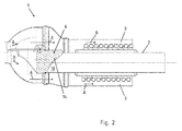
- a spiral tube 4 is arranged, then a not-shown medium is conductive and according to FIG. 2 the heat flowing through the heat exchanger passage 3 exhaust gas A heat.
- the exhaust gas A flows completely through the bypass pipe 2, since in an inlet region 5 of the exhaust gas heat exchanger 1, a valve 6 is rotatably disposed about an axis of rotation 7.
- the adjusting flap 6 has an opening 8, wherein from the opening 8 from a nozzle-shaped portion 9 extends from which comes into positive contact with an inlet 10 of the bypass tube 2.
- the inlet 10 of the bypass tube 2 is expanded outwardly relative to its radial direction.
- the inlet 10 is further tapered in the axial direction of the bypass tube 2 extending to allow a rotational movement of the control valve 6.
- the valve 6 is according to FIG. 1 in the bypass position, so that Exhaust A coming from a not shown exhaust system through the valve 6 is prevented at the inlet 10 into the heat exchanger channel 2 and flows exclusively through the bypass pipe 2. This happens because the valve 6 has an outer peripheral disk body 11, wherein a peripheral edge 12 of the disk body 11 comes to an inner side 13 of the inlet region 5 a form-fitting sealing to the plant.
- a hood 14 is formed on an outer side of the nozzle-shaped portion 9.
- the hood 14 is solid according to this embodiment variant.
- the adjusting flap 6 is brought into the transfer position, so that the exhaust gas A flows through the heat exchanger channel 3.
- the inlet 10 of the bypass pipe 2 is closed, so that here again no exhaust gas can flow through the bypass pipe 2.
- the hood 14 comes to the outwardly widened inlet 10 of the bypass tube 2 form fit and sealing to the plant.
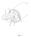
- FIG. 3 and 4 show a respective perspective view of the exhaust gas heat exchanger 1 according to the invention without the housing in the inlet region.
- FIG. 3 is the bypass valve in bypass position, so that the exhaust gas A can flow directly into the bypass pipe 2.
- Well visible here is the rotating disk body 11 and a corresponding outside bearing the axis of rotation 7.
- a locking pin 15 is shown, around which the valve 6 is rotatable.
- the opening 8 itself is only partially cut from the axis of rotation 7 and the locking pin 15.
- the adjusting flap 6 is then rotated about the axis of rotation 7 so that it is in the transmission position.
- Exhaust gas A can thus flow into the heat exchanger duct 3, the bypass pipe 2 being closed by a sealing plate 16 arranged in the region of the hood 14.
- a respective circumferential sealing bead 17 is formed at the opening 8 but also on the sealing plate 16.
- the sealing bead 17 comes into positive engagement with the widened inlet 10 of the bypass tube 2 in the respective bypass position or transmission position.
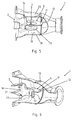
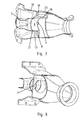
- FIGS. 5 to 8 a further embodiment variant of the exhaust gas heat exchanger 1 according to the invention is shown.
- FIGS. 5 and 6 show The flap 6 has for this purpose an externally rotating disk body 11, in turn with its outer circumferential edge 12 sealingly against an inner circumferential surface 18 of the housing 19 in the bypass position according to the FIG. 7 shown sealingly comes to the plant.
- a bulge 20 on the outer housing 19 in which upon execution of a rotational movement about the axis of rotation 7, the hood 14 shown here is swiveled without contact with the inner jacket surface 18 and then in the bypass position according to FIG. 7 within the inner circumferential surface 18 on the bulge 20 comes form-fitting sealing to the plant.
- the hood 14 is formed in the manner of a scoop.
- sealing plate 16 on the outside of the nozzle-shaped portion 9 of the opening 8.
- a sealing bead 17 is formed, as well as circumferentially at the opening 8.
- the respective sealing bead 17 of the sealing plate 16 comes in the FIGS. 5 and 6 illustrated transfer position form fit to a widening 21 of the inlet 10 of the bypass pipe 2 to the plant, whereas the sealing bead 17 of the nozzle-shaped portion 9 in accordance FIGS. 7 and 8 positively to the widening 21 of the inlet 10 of the bypass tube 2 comes to rest.
- the rotation axis 7 is located in the opening 8. As a result, a very compact dimension is achieved due to the executable rotational movement of the control flap 6.
Landscapes
- Engineering & Computer Science (AREA)
- General Engineering & Computer Science (AREA)
- Mechanical Engineering (AREA)
- Chemical & Material Sciences (AREA)
- Combustion & Propulsion (AREA)
- Physics & Mathematics (AREA)
- Thermal Sciences (AREA)
- Exhaust Silencers (AREA)
Abstract
Description
- Die vorliegende Erfindung betrifft einen Abgaswärmetauscher für ein Kraftfahrzeug gemäß den Merkmalen im Oberbegriff von Patentanspruch 1.
- In Kraftfahrzeugen werden Verbrennungskraftmaschinen eingesetzt, um die im Kraftstoff enthaltene chemische Energie durch den Verbrennungsprozess in mechanische Energie zu wandeln. Der Wirkungsgrad ist dabei auf ca. 40% begrenzt. Dies bedeutet, dass von der im Kraftstoff enthaltenen chemischen Energie 40% in mechanische Energie umsetzbar ist, für den verbleibenden Anteil der Energie wird Wärme produziert, welche dann mit dem Abgasstrom abgeführt wird oder aber in Form von Wärme über den Motorblock oder sonstige Peripheriekomponenten entsprechend an die Umgebung abgegeben wird.
- Für verschiedene Anwendungsfälle ist es vorteilhaft, wenn die im Abgas enthaltene Wärmeenergie genutzt wird. Hierzu sind Abgaswärmetauscher bekannt, durch die einerseits der Abgasstrom zum Entziehen von Wärme geleitet wird und ein zweiter Kanal vorhanden ist, der über ein entsprechendes Medium dann die entzogene Wärme einer weiteren Verwendung zuführt. Dies kann beispielsweise die Beheizung eines Fahrgastinnenraums sein, die Beheizung von anderen Motorkomponenten oder aber auch die Zuführung der Wärme zu einem wärmeabhängigen Kreisprozess ermöglicht wird.
- Bei Start einer Verbrennungskraftmaschine ist diese jedoch zunächst auf Umgebungstemperatur, welche je nach Einsatzgebiet sowie klimatischen Bedingungen in der Regel zwischen -20°C bis +40°C betragen kann. Die Verbrennungskraftmaschine befindet sich dann in der Kaltstartphase, wobei hier die Betriebsflüssigkeiten, beispielsweise Kühlwasser oder aber auch Medien wie z. B. das Motoröl ebenfalls in einem kalten und damit geringer fließfähigem Zustand sind. Ziel ist es nunmehr schnellstmöglich auf die optimale Betriebstemperatur der Verbrennungsmaschine selber sowie aller Peripheriekomponenten zu gelangen.
- Insbesondere im Bereich des Abgasstranges sind Abgasnachbehandlungskomponenten angeordnet und in ihrem Wirkungsgrad für die optimale Betriebstemperatur entsprechend ausgelegt. Bei einem Abgaswärmetauscher ist somit zumeist ein Bypass vorgesehen, so dass beispielsweise zunächst der Abgasstrom vollständig durch den Bypass geführt wird und entsprechend die Abgasnachbehandlungskomponenten schneller aufheizt, wobei im späteren Betrieb dann entsprechend der Abgaswärmetauscher in eine Übertragungsstellung derart gebracht wird, dass dem Abgasstrom Wärme entzogen wird.
- Ein solcher Abgaswärmetauscher ist beispielsweise aus der
EP 1 455 079 B1 bekannt. Damit nunmehr der Abgasstrom nicht durch den Übertragungskanal, sondern durch den Bypasskanal geleitet wird oder umgekehrt, ist ein Stellelement, hier in Form eines Kugelkörpers bekannt, der durch Ausführung einer Drehbewegung entsprechend den Abgasstrom durch den Bypasskanal oder aber den Übertragungskanal lenkt. - Ferner ist aus der
DE 21 26 846 A ein Ableitventil für Kipperfahrzeuge mit beheizten Kippaufbauten bekannt, bei dem eine Stellklappe verwendet wird, um einen Abgasstrom umzuschalten. - Ferner sind diverse Klappenanordnungen aus dem Stand der Technik bekannt.
- Problematisch dabei ist, dass Temperaturen, insbesondere bei Otto-Motoren in Höhe von bis zu mehr als 1000°C im direkten Abgasstrom auftreten, was zu nicht unerheblichen Wärmeausdehnungen und thermische Belastung führt sowie dass das Abgas hoch korrosive Eigenschaften aufweist, denen Abgaskomponenten im direkten Abgasstrom ausgesetzt sind.
- Aufgabe der vorliegenden Erfindung ist es daher ein Stellelement in einem Abgaswärmetauscher zur Ansteuerung unterschiedlicher Kanäle aufzuzeigen, welches einen konstruktiv einfachen Aufbau besitzt, kostengünstig herstellbar ist und gegenüber unterschiedlichen Wärmeausdehnungen unempfindlich ausgebildet ist.
- Die zuvor genannte Aufgabe wird erfindungsgemäß mit einem Abgaswärmetauscher gemäß den Merkmalen im Patentanspruch 1 gelöst.
- Vorteilhafte Ausgestaltungsvarianten der vorliegenden Erfindung sind Gegenstand der abhängigen Patentansprüche.
- Der erfindungsgemäße Abgaswärmetauscher für ein Kraftfahrzeug weist einen Wärmetauscherkanal mit innenliegendem Bypassrohr auf, wobei eine Stellklappe vorgesehen ist, um einen Abgasstrom durch den Wärmetauscherkanal oder den Bypasskanal zu leiten. Erfindungsgemäß ist der Abgaswärmetauscher dadurch gekennzeichnet, dass die Stellklappe eine Öffnung mit einem stutzenförmigen Abschnitt aufweist, wobei in einer Bypassstellung der stutzenförmige Abschnitt mit einem Eintritt des Bypassrohres in strömungsdurchleitendem Kontakt steht und die Stellklappe von einer Bypassstellung in eine Übertragungsstellung schwenkbar ist, in welcher der Eintritt des Bypassrohres verschlossen ist.
- Der Abgaswärmetauscher ist insbesondere als Wärmetauscher ausgebildet, welcher mittig in Längsrichtung erstreckend ein Bypassrohr aufweist, so dass das von einem Abgasrohr kommende Abgas direkt durch das Bypassrohr leitbar ist. Um das Bypassrohr herum befindet sich dann ein Durchströmkanal in Form eines Übertragungskanals. Wird das Abgas nicht durch das Bypassrohr, sondern durch den Übertragungskanal geleitet, ist in dem Übertragungskanal selbst noch ein entsprechender weiterer Kanal ausgebildet, um dann dem Abgas durch ein weiteres Medium Wärme zu entziehen. Beispielsweise kann dieser weitere Kanal in Form einer Spirale um das Bypassrohr gewunden sein, so dass dann die einzelnen Leitungen der Spirale von dem Abgas im Übertragungskanal im Kreuzstrom überströmt werden.
- Um nunmehr wahlweise zwischen einer Bypassstellung oder aber einer Übertragungsstellung zu wählen, ist eine erfindungsgemäße Stellklappe vorgesehen, die insbesondere als einstückig und werkstoffeinheitliches Gußbauteil ausgebildet ist. Die Stellklappe kann zum einen derart betrieben werden, dass ausschließlich die Übertragungsstellung oder aber die Bypassstellung eingenommen wird. Im Rahmen der Erfindung wäre es auch vorstellbar, dass eine entsprechende Zwischenstellung eingenommen wird, um teilweise Abgas durch den Übertragungskanal zu leiten und den verbleibenden Teil durch den entsprechenden Bypass zu leiten. Die Stellklappe kann durch eine Drehbewegung um eine Drehachse innerhalb eines Eintrittsbereiches bzw. Eingangsbereiches des Abgaswärmetauschers von der Übertragungsstellung in die Bypassstellung verbracht werden. Die Klappe ist insbesondere scheibenförmig ausgebildet, wobei ein umlaufender Scheibenköper eine Öffnung, insbesondere im Wesentlichen mittig angeordnet aufweist. In der Bypassstellung verschließt somit der Scheibenkörper dem Abgas den Weg durch den Übertragungskanal und durch die Öffnung kann das Abgas direkt in das Bypassrohr einströmen.
- Bevorzugt ist nunmehr die Stellklappe um eine Drehachse drehbar gelagert, wobei die Drehachse insbesondere im Bereich der Öffnung liegt und die Öffnung selbst durchbrochen ist. Wird nunmehr die Stellklappe um die Drehachse gedreht, so wird der umlaufende Scheibenkörper von einer Stellung orthogonal in Abgasströmungsrichtung liegend gedreht, so dass der Abgasstrom durch den Übertragungskanal verlaufen kann.
- Damit nunmehr der Scheibenkörper über das Bypassrohr bzw. den Eintrittsbereich des Bypassrohres schwenkbar ist und es hier nicht zu einem Verkanten bzw. formschlüssigen Anlagenkontakt kommt, ist weiterhin in dem umlaufenden Scheibenkörper eine Wölbung in Form einer Haube ausgebildet. Die Haube des umlaufenden Scheibenkörpers übergreift dann in der Übertragungsstellung das Bypassrohr, wobei die Haube im Wesentlichen der äußeren Kontur des Bypassrohres entspricht und in der Übertragungsstellung formschlüssig auf einer Außenmantelfläche des Eintrittsbereiches des Bypassrohres zur Anlage kommt.
- Damit nunmehr das Bypassrohr in der Übertragungsstellung ebenfalls verschlossen ist, ist weiterhin eine Dichtplatte in der Stellklappe ausgebildet, wobei in der Übertragungsstellung die Dichtplatte an dem Eintritt des Bypassrohres formschlüssig zur Anlage kommt und diesen abdichtet. Bevorzugt ist dabei die Dichtplatte gleichsam an der Außenfläche des stutzenförmigen Abschnittes ausgebildet, so dass hier eine Bauraumoptimierung bezüglich kompakter Abmaße der Stellklappe bei Ausführen der Drehbewegung um die Drehachse erfolgt.
- Damit nunmehr nicht nur ein formschlüssiger Anlagenkontakt sondern auch eine dichtende Funktion bereitgestellt wird, ist weiterhin der Eintritt des Bypassrohres nach außen hin, insbesondere auf dessen Radialrichtung bezogen aufgeweitet bzw. aufgetulpt. An einer Innenmantelfläche der Aufweitung kommen dann entsprechende Dichtelemente, Dichtkörper oder aber Dichtwulste sowohl in der Übertragungsstellung der Dichtplatte oder aber in der Bypassstellung des stutzenförmigen Abschnittes zur Anlage. Die Dichtelemente und/oder Dichtkörper und/oder Dichtwulste sind bevorzugt an der Stellklappe ausgebildet.
- Damit nunmehr die Drehbewegung innerhalb eines Eintrittsbereiches des Abgaswärmetauchers ausgeführt werden kann, insbesondere unter Berücksichtigung der Haube ist an einem äußeren Gehäuse des Abgaswärmetauschers eine Ausbauchung vorhanden. Die Ausbauchung ist insbesondere auf die Radialrichtung nach außen hin gerichtet. Die Stellklappe und insbesondere die Haube ist dadurch auf einer Innenseite der Ausbauchung vorbeischwenkbar ohne hier in formschlüssigen Anlagenkontakt zu gelangen. In der Bypassstellung kommt eine nach außen umlaufende Kante des Scheibenkörpers mit einer Innenmantelfläche des Gehäuses dichtend zur Anlage. Insbesondere erstreckt sich die außen umlaufende Kante dann auch im Bereich der Haube und kommt auch hier mit der Innenmantelfläche des Gehäuses dichtend zur Anlage.
- Weitere Vorteile, Merkmale, Eigenschaften und Aspekte der vorliegenden Erfindung werden in der nachfolgenden Beschreibung aufgeführt. Bevorzugte Ausführungsvarianten werden in den schematischen Figuren dargestellt. Diese dienen dem einfachen Verständnis der Erfindung. Es zeigen:
- Figur 1 bis 4
- eine erste Ausführungsvariante der erfindungsgemäßen Abgaswärmetauscher mit Bypassklappe in verschiedenen Ansichten und
- Figur 5 bis 8
- eine zweite Ausführungsvariante des erfindungsgemäßen Wärmetauschers in verschiedenen Ansichten.
- In den Figuren werden für gleiche oder ähnliche Bauteile dieselben Bezugszeichen verwendet, auch wenn eine wiederholte Beschreibung aus Vereinfachungsgründen entfällt.
-
Figur 1 zeigt einen erfindungsgemäßen Abgaswärmetauscher 1, aufweisend ein innenliegendes Bypassrohr 2 und ein das Bypassrohr 2 außen umgreifenden Wärmetauscherkanal 3. In dem Wärmetauscherkanal 3 ist um das Bypassrohr 2 gewickelt ein Spiralrohr 4 angeordnet, durch dann ein nicht näher dargestelltes Medium leitbar ist und gemäßFigur 2 dem durch den Wärmetauscherkanal 3 strömendes Abgas A Wärme entzieht. GemäßFigur 1 strömt jedoch das Abgas A vollständig durch das Bypassrohr 2, da in einem Eintrittsbereich 5 des Abgaswärmetauschers 1 eine Stellklappe 6 drehbar um eine Drehachse 7 angeordnet ist. Die Stellklappe 6 weist eine Öffnung 8 auf, wobei sich von der Öffnung 8 aus ein stutzenförmiger Abschnitt 9 aus erstreckt, welcher mit einem Eintritt 10 des Bypassrohres 2 formschlüssig zur Anlage kommt. Der Eintritt 10 des Bypassrohres 2 ist dabei nach außen hin bezogen auf seine Radialrichtung aufgeweitet. Der Eintritt 10 ist ferner in Axialrichtung des Bypassrohres 2 abgeschrägt verlaufend um eine Drehbewegung der Stellklappe 6 zu ermöglichen. Die Stellklappe 6 befindet sich gemäßFigur 1 in der Bypassstellung, so dass das Abgas A kommend von einem nicht näher dargestellten Abgasstrang durch die Stellklappe 6 am Eintritt 10 in den Wärmetauscherkanal 2 gehindert ist und ausschließlich durch das Bypassrohr 2 strömt. Dies geschieht dadurch, dass die Stellklappe 6 einen außen umlaufenden Scheibenkörper 11 aufweist, wobei eine umlaufende Kante 12 des Scheibenkörpers 11 an einer Innenseite 13 des Eintrittsbereichs 5 formschlüssig dichtend zur Anlage kommt. Auf einer Außenseite des stutzenförmigen Abschnittes 9 ist eine Haube 14 ausgebildet. Die Haube 14 ist gemäß dieser Ausführungsvariante massiv ausgebildet. - Gemäß
Figur 2 ist die Stellklappe 6 in Übertragungsstellung gebracht, so dass das Abgas A durch den Wärmetauscherkanal 3 strömt. Durch die Haube 14 selbst ist der Eintritt 10 des Bypassrohres 2 geschlossen, so dass hier wiederum kein Abgas durch das Bypassrohr 2 strömen kann. Die Haube 14 kommt dabei an dem nach außen aufgeweiteten Eintritt 10 des Bypassrohres 2 formschlüssig und dichtend zur Anlage. -
Figur 3 und4 zeigen eine jeweils perspektivische Ansicht des erfindungsgemäßen Abgaswärmetauschers 1 ohne das Gehäuse im Eintrittsbereich. InFigur 3 ist dabei die Bypassklappe in Bypassstellung, so dass das Abgas A direkt in das Bypassrohr 2 strömen kann. Gut ersichtlich ist hier der umlaufende Scheibenkörper 11 sowie eine entsprechende außenseitige Lagerung der Drehachse 7. Hier ist ein Steckbolzen 15 dargestellt, um den die Stellklappe 6 drehbar ausgebildet ist. Die Öffnung 8 selbst ist dabei von der Drehachse 7 bzw. dem Steckbolzen 15 nur teilweise angeschnitten. - Gemäß
Figur 4 ist die Stellklappe 6 dann um die Drehachse 7 gedreht, so dass diese sich in Übertragungsstellung befindet. Abgas A kann somit in den Wärmetauscherkanal 3 einströmen, wobei das Bypassrohr 2 durch eine im Bereich der Haube 14 angeordnete Dichtplatte 16 geschlossen ist. Bevorzugt ist an der Öffnung 8 aber auch an der Dichtplatte 16 eine jeweils umlaufende Dichtwulst 17 ausgebildet. Die Dichtwulst 17 kommt besonders bevorzugt formschlüssig an dem aufgeweiteten Eintritt 10 des Bypassrohres 2 in der jeweiligen Bypassstellung oder aber Übertragungsstellung zur Anlage. - In den
Figuren 5 bis 8 ist eine weitere Ausgestaltungsvariante des erfindungsgemäßen Abgaswärmetauschers 1 dargestellt.Figur 5 und 6 zeigen dabei den Abgaswärmetauscher 1 in der Übertragungsstellung mit geöffneter Stellklappe 6. Die Stellklappe 6 weist dazu einen außen umlaufenden Scheibenkörper 11 auf, der wiederum mit seiner außen umlaufenden Kante 12 dichtend an einer Innenmantelfläche 18 des Gehäuses 19 in der Bypassstellung gemäß derFigur 7 dargestellt dichtend zur Anlage kommt. Weiterhin gut ersichtlich inFigur 5 ist eine Ausbauchung 20 an dem äußeren Gehäuse 19, in der bei Ausführung einer Drehbewegung um die Drehachse 7 die hier dargestellte Haube 14 ohne Anlagenkontakt mit der Innenmantelfläche 18 durchschwenkbar ist und dann in der Bypassstellung gemäßFigur 7 innerhalb der Innenmantelfläche 18 an der Ausbauchung 20 formschlüssig dichtend zur Anlage kommt. Die Haube 14 ist dabei nach Art einer Hutze ausgebildet. - Ferner dargestellt ist die Dichtplatte 16 an der Außenseite des stutzenförmigen Abschnittes 9 der Öffnung 8. Umlaufend an der Dichtplatte 16 ist eine Dichtwulst 17 ausgebildet, genauso wie umlaufend an der Öffnung 8. Der jeweilige Dichtwulst 17 der Dichtplatte 16 kommt in der
Figur 5 und 6 dargestellten Übertragungsstellung formschlüssig an einer Aufweitung 21 des Eintritts 10 des Bypassrohres 2 zur Anlage, wohingegen der Dichtwulst 17 des stutzenförmigen Abschnittes 9 gemäßFigur 7 und 8 formschlüssig an der Aufweitung 21 des Eintritts 10 des Bypassrohres 2 zur Anlage kommt. Ebenfalls gut ersichtlich ist, dass in der hier dargestellten Ausgestaltungsvariante die Drehachse 7 in der Öffnung 8 liegt. Hierdurch wird ein sehr kompaktes Abmaß aufgrund der ausführbaren Drehbewegung der Stellklappe 6 erreicht. -
- 1 -
- Abgaswärmetauscher
- 2 -
- Bypassrohr
- 3 -
- Wärmetauscherkanal
- 4 -
- Spiralrohr
- 5 -
- Eintrittsbereich zu 1
- 6 -
- Stellklappe
- 7 -
- Drehachse
- 8 -
- Öffnung zu 6
- 9 -
- stutzenförmiger Abschnitt
- 10 -
- Eintritt zu 2
- 11 -
- Scheibenkörper
- 12 -
- Kante
- 13 -
- Innenseite zu 5
- 14 -
- Haube
- 15 -
- Steckbolzen
- 16 -
- Dichtplatte
- 17 -
- Dichtwulst
- 18 -
- Innenmantelfläche zu 19
- 19 -
- Gehäuse
- 20 -
- Ausbauchung zu 19
- 21 -
- Aufweitung
- A -
- Abgas
Claims (8)
- Abgaswärmetauscher (1) für ein Kraftfahrzeug, aufweisend einen umlaufenden Wärmetauscherkanal (3) mit innenliegendem Bypassrohr (2), wobei eine Stellklappe (6) vorgesehen ist um einen Abgasstrom durch den Wärmetauscherkanal (3) oder den Bypasskanal zu leiten, dadurch gekennzeichnet, dass die Stellklappe (6) eine Öffnung (8) mit einem stutzenförmigen Abschnitt (9) aufweist, wobei in einer Bypassstellung der stutzenförmige Abschnitt (9) mit einem Eintritt (10) des Bypassrohrs (2) in strömungsdurchleitendem Kontakt steht und die Stellklappe (6) von einer Bypasstellung in eine Übertragungsstellung drehbar ist in welcher der Eintritt (10) verschlossen ist.
- Abgaswärmetauscher nach Anspruch 1, dadurch gekennzeichnet, dass die Stellklappe (6) einen außen umlaufenden Scheibenkörper (11) aufweist, wobei der Scheibenkörper (11) in der Bypassstellung einen Wärmetauschereintritt des Wärmetauscherkanals (3) verschließt.
- Abgaswärmetauscher nach Anspruch 2, dadurch gekennzeichnet, dass an einer Außenseite des stutzenförmigen Abschnittes (9) und in dem Scheibenkörper (11) eine Haube (14) ausgebildet ist, wobei die Haube (14) in der Wärmetauscherstellung das Bypassrohr (2) zumindest abschnittsweise übergreift.
- Abgaswärmetauscher nach einem der Ansprüche 1 bis 3, dadurch gekennzeichnet, dass an der Außenfläche des stutzenförmigen Abschnittes (9) eine Dichtplatte (16) ausgebildet ist, welche in der Übertragungsstellung den Eintritt (10) des Bypassrohres (2) abdichtet.
- Abgaswärmetauscher nach einem der Ansprüche 1 bis 4, dadurch gekennzeichnet, dass das Bypassrohr (2) am Eintritt (10) aufgeweitet ist, wobei der stutzenförmige Abschnitt (9) oder die Dichtplatte (16) mit einem umlaufenden Dichtwulst (17) an einer Innenmantelfläche der Aufweitung (21) dichtend zur Anlage kommen.
- Abgaswärmetauscher nach einem der Ansprüche 1 bis 5, dadurch gekennzeichnet, dass die Stellklappe (6) um eine Drehachse (7) drehbar gelagert ist, wobei die Drehachse (7) die Öffnung (8) durchgreift.
- Abgaswärmetauscher nach einem der Ansprüche 1 bis 6, dadurch gekennzeichnet, dass an einem äußeren Gehäuse (19) eine Ausbauchung (20) vorhanden ist, wobei die Haube (14) an einer Innenseite der Ausbauchung vorbeischwenkbar ist und in der Bypasstellung mit einer Innenmantelfläche (18) des Gehäuses (19) im Bereich der Ausbauchung (20) dichtend zur Anlage kommt.
- Abgaswärmetauscher nach einem der vorhergehenden Ansprüche, dadurch gekennzeichnet, dass die Stellklappe (6) einstückig und werkstoffeinheitlich, insbesondere als Gußbauteil ausgebildet ist.
Applications Claiming Priority (1)
| Application Number | Priority Date | Filing Date | Title |
|---|---|---|---|
| DE102014106386.4A DE102014106386B4 (de) | 2014-05-07 | 2014-05-07 | Abgaswärmetauscher mit Bypassrohr |
Publications (1)
| Publication Number | Publication Date |
|---|---|
| EP2942500A1 true EP2942500A1 (de) | 2015-11-11 |
Family
ID=52991503
Family Applications (1)
| Application Number | Title | Priority Date | Filing Date |
|---|---|---|---|
| EP15163686.7A Withdrawn EP2942500A1 (de) | 2014-05-07 | 2015-04-15 | Abgaswärmetauscher mit bypassrohr |
Country Status (4)
| Country | Link |
|---|---|
| US (1) | US9964075B2 (de) |
| EP (1) | EP2942500A1 (de) |
| JP (1) | JP6004597B2 (de) |
| DE (1) | DE102014106386B4 (de) |
Cited By (4)
| Publication number | Priority date | Publication date | Assignee | Title |
|---|---|---|---|---|
| EP3293379A1 (de) * | 2016-09-12 | 2018-03-14 | Volvo Car Corporation | Kombinierter wärmetauscher und auspuffschalldämpfer |
| WO2018224295A1 (de) * | 2017-06-08 | 2018-12-13 | Volkswagen Aktiengesellschaft | Vorrichtung zur wärmerückgewinnung aus einem heizfluid |
| EP3462063A1 (de) * | 2017-09-29 | 2019-04-03 | Bosal Emission Control Systems NV | Wärmerückgewinnungskomponente für ein abgassystem |
| US10731608B2 (en) * | 2018-01-26 | 2020-08-04 | Futaba Industrial Co., Ltd. | Exhaust heat recovery device |
Families Citing this family (2)
| Publication number | Priority date | Publication date | Assignee | Title |
|---|---|---|---|---|
| JP6695816B2 (ja) * | 2017-02-23 | 2020-05-20 | 株式会社豊田自動織機 | 流路切替弁 |
| CN120760510B (zh) * | 2025-09-11 | 2025-11-21 | 山西龙腾盛海科技有限公司 | 一种废气处理用降温装置 |
Citations (5)
| Publication number | Priority date | Publication date | Assignee | Title |
|---|---|---|---|---|
| DE2126846A1 (de) | 1970-06-03 | 1971-12-16 | Euclid, Inc , Cleveland, Ohio (V St A) | Ableitveml für Kipper Kraftfahrzeuge mit beheizten Kippaufbauten |
| EP0272680A2 (de) * | 1986-12-26 | 1988-06-29 | Isuzu Motors Limited | Turbo-Verbund-Maschine |
| FR2891589A1 (fr) * | 2005-09-30 | 2007-04-06 | Renault Sas | Refroidisseur de gaz recircules |
| EP1455079B1 (de) | 2003-03-04 | 2009-03-11 | Benteler Automobiltechnik GmbH | Vorrichtung zur Wärmeübertragung zwischen dem Abgas eines Verbrennungsmotors und einem Kühlmittel |
| EP2693011A1 (de) * | 2012-07-30 | 2014-02-05 | Benteler Automobiltechnik GmbH | Abgasklappenanordnung mit integriertem Bypass |
Family Cites Families (7)
| Publication number | Priority date | Publication date | Assignee | Title |
|---|---|---|---|---|
| US3501128A (en) * | 1966-07-07 | 1970-03-17 | Rockwell Mfg Co | Ball valves |
| JPH0610147Y2 (ja) * | 1987-06-12 | 1994-03-16 | 本田技研工業株式会社 | 排気管構造 |
| JP2585960B2 (ja) * | 1993-10-06 | 1997-02-26 | 大明金属工業株式会社 | ボール栓 |
| US20050133202A1 (en) * | 2001-11-09 | 2005-06-23 | Aalborg Industries A/S | Heat exchanger, combination with heat exchanger and method of manufacturing the heat exchanger |
| KR100590960B1 (ko) * | 2004-04-06 | 2006-06-19 | 현대자동차주식회사 | 자동차 배기가스 정화시스템 |
| JP2008069750A (ja) * | 2006-09-15 | 2008-03-27 | Toyota Motor Corp | 排気熱回収装置 |
| JP2011214537A (ja) * | 2010-04-01 | 2011-10-27 | Sakamoto Industry Co Ltd | 排気ガス熱回収装置 |
-
2014
- 2014-05-07 DE DE102014106386.4A patent/DE102014106386B4/de not_active Expired - Fee Related
-
2015
- 2015-04-15 EP EP15163686.7A patent/EP2942500A1/de not_active Withdrawn
- 2015-04-21 JP JP2015086419A patent/JP6004597B2/ja not_active Expired - Fee Related
- 2015-05-06 US US14/705,670 patent/US9964075B2/en not_active Expired - Fee Related
Patent Citations (5)
| Publication number | Priority date | Publication date | Assignee | Title |
|---|---|---|---|---|
| DE2126846A1 (de) | 1970-06-03 | 1971-12-16 | Euclid, Inc , Cleveland, Ohio (V St A) | Ableitveml für Kipper Kraftfahrzeuge mit beheizten Kippaufbauten |
| EP0272680A2 (de) * | 1986-12-26 | 1988-06-29 | Isuzu Motors Limited | Turbo-Verbund-Maschine |
| EP1455079B1 (de) | 2003-03-04 | 2009-03-11 | Benteler Automobiltechnik GmbH | Vorrichtung zur Wärmeübertragung zwischen dem Abgas eines Verbrennungsmotors und einem Kühlmittel |
| FR2891589A1 (fr) * | 2005-09-30 | 2007-04-06 | Renault Sas | Refroidisseur de gaz recircules |
| EP2693011A1 (de) * | 2012-07-30 | 2014-02-05 | Benteler Automobiltechnik GmbH | Abgasklappenanordnung mit integriertem Bypass |
Cited By (8)
| Publication number | Priority date | Publication date | Assignee | Title |
|---|---|---|---|---|
| EP3293379A1 (de) * | 2016-09-12 | 2018-03-14 | Volvo Car Corporation | Kombinierter wärmetauscher und auspuffschalldämpfer |
| US10508580B2 (en) | 2016-09-12 | 2019-12-17 | Volvo Car Corporation | Combined heat exchanger and exhaust silencer |
| WO2018224295A1 (de) * | 2017-06-08 | 2018-12-13 | Volkswagen Aktiengesellschaft | Vorrichtung zur wärmerückgewinnung aus einem heizfluid |
| EP3462063A1 (de) * | 2017-09-29 | 2019-04-03 | Bosal Emission Control Systems NV | Wärmerückgewinnungskomponente für ein abgassystem |
| CN109578121A (zh) * | 2017-09-29 | 2019-04-05 | 博萨尔排放控制系统公司 | 用于废气系统的热回收部件 |
| CN109578121B (zh) * | 2017-09-29 | 2022-03-04 | 博萨尔排放控制系统公司 | 用于废气系统的热回收部件 |
| US11359534B2 (en) | 2017-09-29 | 2022-06-14 | Bosal Emission Control Systems Nv | Heat recovery component for an exhaust gas system |
| US10731608B2 (en) * | 2018-01-26 | 2020-08-04 | Futaba Industrial Co., Ltd. | Exhaust heat recovery device |
Also Published As
| Publication number | Publication date |
|---|---|
| JP2015214969A (ja) | 2015-12-03 |
| DE102014106386A1 (de) | 2015-11-12 |
| JP6004597B2 (ja) | 2016-10-12 |
| US20150322899A1 (en) | 2015-11-12 |
| US9964075B2 (en) | 2018-05-08 |
| DE102014106386B4 (de) | 2016-08-11 |
Similar Documents
| Publication | Publication Date | Title |
|---|---|---|
| DE102014106386B4 (de) | Abgaswärmetauscher mit Bypassrohr | |
| DE102017124725A1 (de) | Steuerungsventil | |
| DE102012106888B4 (de) | Abgasklappenanordnung mit integriertem Bypass | |
| WO2008043429A1 (de) | Ventilvorrichtung | |
| EP1291509A2 (de) | Ventilkomponentensatz für interne Bypass-Strömung | |
| DE102010010624A1 (de) | Koaxialer Wärmetauscher für eine Kraftfahrzeug-Abgasanlage | |
| EP1311754B1 (de) | Ventilanordnung mit doppelklappe und wärmebrücke für ein abgasrückführungssystem und verfahren zu deren betrieb | |
| DE102012202390B4 (de) | Wärmetauscher-System für eine Abgasanlage einer Brennkraftmaschine | |
| DE102010010332B4 (de) | Abgassystem für eine Verbrennungskraftmaschine sowie Verfahren zur Reinigung eines Abgasrückführventils eines Abgassystems | |
| DE102014206529A1 (de) | Wärmemanagementmodul mit Drehschiebertechnologie | |
| WO2014075772A1 (de) | Regelvorrichtung für einen abgasführungsabschnitt einer turbine und abgasführungsabschnitt für eine turbine | |
| DE102017218302A1 (de) | Ventileinrichtung zum Steuern eines Abgasstroms | |
| DE102020213993A1 (de) | Ventil und Vorrichtung zum Erhitzen von Öl mittels Abgaswärme | |
| DE202015101120U1 (de) | Wärmetauscheranordnung sowie Abgassystem für eine Brennkraftmaschine eines Kraftfahrzeugs | |
| DE102015105219A1 (de) | Regelvorrichtung für einen Abgasführungsabschnitt eines Abgasturboladers | |
| DE102015203001B3 (de) | Wärmetauscheranordnung sowie Abgassystem für eine Brennkraftmaschine eines Kraftfahrzeugs | |
| DE102018115445A1 (de) | Regelvorrichtung für einen Abgasführungsabschnitt eines Abgasturboladers | |
| DE102015111252B4 (de) | Ventil für einen Abgasstrang einer Brennkraftmaschine | |
| DE102013103507A1 (de) | Regelvorrichtung für einen Abgasführungsabschnitt einer Turbine | |
| EP1455079B1 (de) | Vorrichtung zur Wärmeübertragung zwischen dem Abgas eines Verbrennungsmotors und einem Kühlmittel | |
| DE102007017658B4 (de) | Vorrichtung zur Steuerung/Regelung eines Abgasstromes, Wärmetauscher, System | |
| DE102015002725A1 (de) | Thermostatventil für ein Kühlsystem einer Verbrennungskraftmaschine, insbesondere eines Kraftwagens | |
| DE102014201085A1 (de) | Abgasrückführventil | |
| DE102018200662B4 (de) | Abgaskrümmer mit Doppelgehäuse, Brennkraftmaschine mit einem solchen Abgaskrümmer und Verfahren zum Betreiben einer solchen Brennkraftmaschine | |
| DE102015203004A1 (de) | Wärmetauscheranordnung sowie Abgassystem für eine Brennkraftmaschine eines Kraftfahrzeugs |
Legal Events
| Date | Code | Title | Description |
|---|---|---|---|
| PUAI | Public reference made under article 153(3) epc to a published international application that has entered the european phase |
Free format text: ORIGINAL CODE: 0009012 |
|
| AK | Designated contracting states |
Kind code of ref document: A1 Designated state(s): AL AT BE BG CH CY CZ DE DK EE ES FI FR GB GR HR HU IE IS IT LI LT LU LV MC MK MT NL NO PL PT RO RS SE SI SK SM TR |
|
| AX | Request for extension of the european patent |
Extension state: BA ME |
|
| 17P | Request for examination filed |
Effective date: 20160308 |
|
| RIC1 | Information provided on ipc code assigned before grant |
Ipc: F01N 3/04 20060101AFI20160729BHEP Ipc: F28F 27/02 20060101ALI20160729BHEP Ipc: F02M 26/32 20160101ALI20160729BHEP Ipc: F28D 21/00 20060101ALI20160729BHEP Ipc: F28D 7/10 20060101ALI20160729BHEP Ipc: F16K 11/052 20060101ALI20160729BHEP Ipc: F02D 9/04 20060101ALI20160729BHEP Ipc: F16K 1/22 20060101ALI20160729BHEP Ipc: F28D 7/02 20060101ALI20160729BHEP Ipc: F02D 9/10 20060101ALI20160729BHEP |
|
| 17Q | First examination report despatched |
Effective date: 20161122 |
|
| GRAP | Despatch of communication of intention to grant a patent |
Free format text: ORIGINAL CODE: EPIDOSNIGR1 |
|
| INTG | Intention to grant announced |
Effective date: 20170330 |
|
| STAA | Information on the status of an ep patent application or granted ep patent |
Free format text: STATUS: THE APPLICATION HAS BEEN WITHDRAWN |
|
| 18W | Application withdrawn |
Effective date: 20170523 |