EP2942388A1 - Procédé de production de biogaz et installation de biogaz - Google Patents
Procédé de production de biogaz et installation de biogaz Download PDFInfo
- Publication number
- EP2942388A1 EP2942388A1 EP14167591.8A EP14167591A EP2942388A1 EP 2942388 A1 EP2942388 A1 EP 2942388A1 EP 14167591 A EP14167591 A EP 14167591A EP 2942388 A1 EP2942388 A1 EP 2942388A1
- Authority
- EP
- European Patent Office
- Prior art keywords
- fermentation
- digestate
- hydrolysis
- hydrolysis reactor
- chemical
- Prior art date
- Legal status (The legal status is an assumption and is not a legal conclusion. Google has not performed a legal analysis and makes no representation as to the accuracy of the status listed.)
- Withdrawn
Links
Images

Classifications
-
- C—CHEMISTRY; METALLURGY
- C12—BIOCHEMISTRY; BEER; SPIRITS; WINE; VINEGAR; MICROBIOLOGY; ENZYMOLOGY; MUTATION OR GENETIC ENGINEERING
- C12M—APPARATUS FOR ENZYMOLOGY OR MICROBIOLOGY; APPARATUS FOR CULTURING MICROORGANISMS FOR PRODUCING BIOMASS, FOR GROWING CELLS OR FOR OBTAINING FERMENTATION OR METABOLIC PRODUCTS, i.e. BIOREACTORS OR FERMENTERS
- C12M21/00—Bioreactors or fermenters specially adapted for specific uses
- C12M21/04—Bioreactors or fermenters specially adapted for specific uses for producing gas, e.g. biogas
-
- C—CHEMISTRY; METALLURGY
- C12—BIOCHEMISTRY; BEER; SPIRITS; WINE; VINEGAR; MICROBIOLOGY; ENZYMOLOGY; MUTATION OR GENETIC ENGINEERING
- C12M—APPARATUS FOR ENZYMOLOGY OR MICROBIOLOGY; APPARATUS FOR CULTURING MICROORGANISMS FOR PRODUCING BIOMASS, FOR GROWING CELLS OR FOR OBTAINING FERMENTATION OR METABOLIC PRODUCTS, i.e. BIOREACTORS OR FERMENTERS
- C12M45/00—Means for pre-treatment of biological substances
- C12M45/06—Means for pre-treatment of biological substances by chemical means or hydrolysis
-
- C—CHEMISTRY; METALLURGY
- C12—BIOCHEMISTRY; BEER; SPIRITS; WINE; VINEGAR; MICROBIOLOGY; ENZYMOLOGY; MUTATION OR GENETIC ENGINEERING
- C12M—APPARATUS FOR ENZYMOLOGY OR MICROBIOLOGY; APPARATUS FOR CULTURING MICROORGANISMS FOR PRODUCING BIOMASS, FOR GROWING CELLS OR FOR OBTAINING FERMENTATION OR METABOLIC PRODUCTS, i.e. BIOREACTORS OR FERMENTERS
- C12M47/00—Means for after-treatment of the produced biomass or of the fermentation or metabolic products, e.g. storage of biomass
- C12M47/18—Gas cleaning, e.g. scrubbers; Separation of different gases
-
- Y—GENERAL TAGGING OF NEW TECHNOLOGICAL DEVELOPMENTS; GENERAL TAGGING OF CROSS-SECTIONAL TECHNOLOGIES SPANNING OVER SEVERAL SECTIONS OF THE IPC; TECHNICAL SUBJECTS COVERED BY FORMER USPC CROSS-REFERENCE ART COLLECTIONS [XRACs] AND DIGESTS
- Y02—TECHNOLOGIES OR APPLICATIONS FOR MITIGATION OR ADAPTATION AGAINST CLIMATE CHANGE
- Y02E—REDUCTION OF GREENHOUSE GAS [GHG] EMISSIONS, RELATED TO ENERGY GENERATION, TRANSMISSION OR DISTRIBUTION
- Y02E50/00—Technologies for the production of fuel of non-fossil origin
- Y02E50/30—Fuel from waste, e.g. synthetic alcohol or diesel
Definitions
- the invention relates to a method and a biogas plant for producing biogas from biomass, such as energy crops, manure, solid manure, biowaste or agricultural by-products, e.g. Slaughterhouse waste.
- biomass such as energy crops, manure, solid manure, biowaste or agricultural by-products, e.g. Slaughterhouse waste.
- methane-containing gas is generated by fermentation of a plant substrate, which can be used for power and / or heat generation.
- the analgesic substrate of a biogas plant consists largely, i. at least 80% of organic, microbially degradable biomass.
- the fermentation process takes place in an airtight fermentation tank or fermentation reactor under anaerobic conditions. Microorganisms metabolize carbohydrates, fats and proteins contained in the biomass and produce methane and carbon dioxide.
- a method for generating biogas from organic biomass such as energy crops, liquid manure, solid manure or biowaste, struck in a biogas plant with at least one fermentation tank and a hydrolysis reactor, wherein the biomass is pre-densified to form a digestate in the at least one fermentation tank.
- the biomass is considered the main component, i. H. with a proportion of at least 75%, fed to a plant substrate in the at least one fermentation tank.
- the plant substrate and the biomass contained in the plant substrate are heated to a pre-fermentation temperature.
- the VorvergärungsRIS resulting biogas can be removed from the at least one fermentation tank and stored.
- the fermentation residue is removed from the fermentation tank into the hydrolysis reactor.
- at least a portion of the digestate in the hydrolysis reactor is hydrolyzed. Following the hydrolysis, the hydrolyzed digestate is post-fermented in a fermentation tank.
- the pre-fermented digestate is chemically hydrolyzed, ie the breakdown of the chemical compounds in the biomass is added to the hydrolysis reactor by adding a predetermined amount of the PH value of the pre-fermented fermentation residue. It was found that the change in the pH, in particular by increasing the H + or OH concentration in the hydrolysis reactor, could considerably accelerate the splitting of the sugars, starch and protein components of the biomass. Since the monomers resulting from the cleavage are decomposed comparatively efficiently by the microorganisms of the subsequent post-fermentation, it was possible to achieve a significantly increased gas yield upon post-fermentation of the hydrolyzed digestate.
- a chemical is added to the fermentation substrate for chemical hydrolysis to form a digestate chemical mixture.
- the chemical contains an acid or base.
- the chemical has a PH of at least 12, preferably at least about 13.
- the chemical has a pH of at most 3, preferably at most about 2.
- the digestate chemical mixture is kept mixed during the hydrolysis by an agitator.
- the pH of the digestate chemical mixture is between about 9 and about 13, preferably between about 10 and about 12 set. It was found that the organic acids released in the hydrolysis process, if the chemical hydrolysis is set at least at the initiation of hydrolysis in the alkaline range, can almost completely neutralize the hydrolyzed fermentation substrate. Since a neutral level is desirable for the post-fermentation, additional process steps for the treatment of the hydrolyzed fermentation residue for the post-fermentation can preferably be completely eliminated.
- the pre-fermented digestate is aerobic, preferably hydrolyzed weakly aerobically.
- the pre-fermented fermentation residue is heated to a predetermined hydrolysis temperature before and / or while it is hydrolyzed, but in particular after the pre-fermentation.
- the pre-fermented digestate is heated in a heat exchanger.
- the digestate is passed through two heat exchangers connected in series.
- the heat exchanger connected in series works bidirectionally.
- the hydrolysis temperature is between 20 ° C and 100 ° C, preferably between 60 ° C and 90 ° C, more preferably between about 75 ° C and 85 ° C.
- the hydrolyzed digestate is cooled from a hydrolysis temperature to a predetermined post-fermentation temperature prior to post-fermentation.
- the hydrolyzed digestate passed through the first particular bidirectional heat exchanger.
- the post-fermentation temperature of the digestate is adjusted to between 20 ° C and about 70 ° C, preferably between about 50 ° C and about 60 ° C.
- the resulting in the hydrolysis in the hydrolysis reactor gases are removed from the hydrolysis reactor.
- the removed gases are enriched with sulfuric acid using a gas scrubber. It was found that the removal of the gases formed in the hydrolysis process triggered a nitrogen and sulfur degradation in the hydrolyzed digestate. This achieves improved post-fermentation and improves the biogas quality with regard to combustion in gas engines. In addition, a safety threshold could be undershot with respect to the agricultural processing of the digestate.
- ammonium sulfate is produced, which can be further used as an additive for fertilizers.
- the hydrolyzed digestate is treated prior to post-fermentation with a pH-altering chemical.
- the pH of the digestate is set to be substantially neutral. This process step is carried out only as needed, provided that the hydrolysis is carried out in the acidic range or the immanent in the alkaline hydrolysis self-neutralization is insufficient.
- the hydrolyzed digestate is post-fermented in the same fermentation vessel in which the biomass has been pre-fermented.
- this procedure it is particularly advantageous that only one fermentation container must be provided, whereby the process cost is significantly reduced.
- the method operates according to the operation of the biogas plant according to the invention described below.
- the invention also relates to a biogas plant for the production of biogas from organic biomass, such as energy crops, manure, solid manure or biowaste.
- the biogas plant comprises a fermentation tank in which biomass or fermentation residue to be fermented can be introduced and from which biogas and a fermented fermentation residue can be removed, as well as a hydrolysis reactor which can be connected to the fermentation tank in order to receive the fermented fermentation residue from the fermentation tank.
- at least one metering device is provided, which is connected to a chemical reservoir and the hydrolysis reactor and designed to supply a defined amount of a chemical to the hydrolysis reactor.
- the biogas plant has at least one heat exchanger which can be connected to the fermentation vessel and the hydrolysis reactor and is designed to heat a fermentation residue withdrawn from the fermentation vessel and / or to cool a hydrolyzed digestate from the hydrolysis reactor.
- the heat exchanger is connected via a hot water pipe system with a combined heat and power plant.
- the biogas plant has a gas power network for supplying the combined heat and power plant with biogas.
- the invention also relates to a system for generating electrical and / or thermal energy, which comprises a biogas plant and a combined heat and power plant connected to the biogas plant via a gas pipeline network.
- the hydrolysis reactor is resistant to chemicals, especially designed completely acid and / or base resistant.
- the hydrolysis reactor is base stable up to a pH of 13.
- the hydrolysis reactor has a ventilation device for supplying oxygen in the hydrolysis reactor, which in particular comprises an air throttle device for adjusting the amount of oxygen introduced.
- a ventilation device for supplying oxygen in the hydrolysis reactor which in particular comprises an air throttle device for adjusting the amount of oxygen introduced.
- the biogas plant on a second fermentation tank, which is connected downstream of the hydrolysis reactor.
- the second fermentation vessel receives the hydrolyzed digestate of the hydrolysis reactor for post-fermentation.
- the biogas plant comprises only one fermentation tank, which is upstream of the hydrolysis reactor as well as downstream.
- the single fermentation tank is used for pre-fermentation and post-fermentation, which minimizes the maintenance and investment costs as well as the space required.
- FIG. 1 a biogas plant (100) according to the invention for producing biogas from organic biomass is shown, which has two fermentation tanks (1, 5). To the two fermentation tanks (1, 5) each have a biomass supply line (19) is connected. The fermentation containers (1, 5) are hermetically sealed to ensure an anaerobic fermentation process within the container. Also, a respective connection point of the supply lines (19) to the fermentation tank (1, 5) and all other connections mentioned below to the fermentation tank (1, 5) may also be made airtight that the anaerobic fermentation is not affected by air flow.
- the fermentation reactor (1) is connected via a line (11a) to a heat exchanger (2).
- the heat exchanger (2) is designed in a first operating mode by to heat the fermentation residue guided in the heat exchanger and, in a second operating mode, to cool the digestate passed through the heat exchanger (2).
- the heat exchanger (2) is connected via a line (14c) with the second fermentation tank (5) and via a line (11b) with a second heat exchanger (3).
- the connecting line (11b) between the heat exchangers can be thermally insulated in order to avoid energy losses during the stepwise heating and forwarding of the fermentation residue.
- a conduit (11c) connects the second heat exchanger (3) to a hydrolysis reactor (4).
- Attached to the hydrolysis reactor (4) is a chemical metering device (8) connected to the hydrolysis reactor (4) via a chemical resistant conduit (12).
- the metering device (8) is connected to a non-illustrated chemical storage, which may also be part of the metering device and in which one of the metering device to the hydrolysis reactor (4) stores stock of a chemical stores.
- the hydrolysis reactor (4) comprises a receiving space in which the pre-fermented fermentation residue is held together with a chemical delivered by the metering device (8).
- a heater (not shown in detail) is preferably provided in a wall of the receiving space, by means of which a digestate chemical mixture can be maintained at a predetermined hydrolysis temperature.
- the hydrolysis reactor (4) furthermore has an agitator (not shown in more detail) arranged in the receiving space, by means of which the digestate chemical mixture is kept in motion and / or mixed, in particular during the entire residence time in the hydrolysis reactor (4).
- a ventilation device (not shown in detail) is installed, which connects, for example, the atmosphere with the receiving space and by means of which the hydrolysis reactor oxygen controlled can be supplied.
- the ventilation device has a throttle device (not shown in detail), which is controlled for example via a control algorithm such that within the hydrolysis reactor (4), a slightly aerobic environment is reached.
- the ventilation device can be realized by one or more openings in the wall of the hydrolysis reactor (4), which is / are closed fluid-tight if necessary.
- the hydrolysis reactor is made of a chemical-resistant material or at least on its coming into contact with the digestate chemical mixture inner wall chemically resistant clad or coated. Finally, the hydrolysis reactor is connected to a scrubber (6) via the line (13).
- the gas scrubber (6) may have a gas transport device, not shown, by means of the via the line (13) resulting in the hydrolysis hydrolysis gases from the top of the hydrolysis reactor (4) are discharged into the gas scrubber (6).
- the hydrolysis gases contain high levels of carbon dioxide, hydrogen sulfide and ammonia.
- the ammonia content of the hydrolysis gases can be processed to ammonium sulfate, which can be used as a fertilizer additive.
- the gas scrubber (6) with a sulfuric acid source (23) via a line (24) and in particular equipped with a control that adjusts the proportion of hydrolysis gases and sulfuric acid in the gas scrubber such that ammonium sulfate is recovered.
- the gas scrubber (6) has a recyclable material outlet (22), via which the recovered ammonium sulfate is removed from the gas scrubber (6).
- the hydrolysis reactor Via the discharge line (14a, 14b), the hydrolysis reactor is connected directly to the heat exchanger (2).
- the discharge line (14a, 14b) also opens a feed line (21), which is connected to a neutralization meter (20).
- the neutralization doser obtains a chemical for neutralizing the chemical supplied from the metering device (8) from a non-illustrated chemical storage.
- the biogas plant comprises a central chemical storage, which stores the chemicals used by the metering device (8) and the neutralization meter (20) and the sulfuric acid required by the gas scrubber.
- the chemical storage has separate compartments for the respective chemical.
- the metering device (8) and the neutralization meter (20) are formed by a single metering module with a common control logic.
- the fermentation tank (5) connected downstream of the heat exchanger (2) is connected to a separating device (9) via a discharge line (16).
- the separating device (9) is designed to separate a solids content of the fermentation residue withdrawn from the fermentation tank (5) from a liquid fraction.
- the separating device (9) has a solids outlet, which is connected via a solids line (18) to a solid-material bearing (7).
- the liquid fraction split off from the fermentation residue, also called recirculate is fed from a recirculation outlet of the separating device (9) via a recirculation line (17) designed for liquid transport to the first fermentation vessel (1) as required.
- the digestate passes via the line (11a) into the first heat exchanger (2), in which the digestate is heated from about 40 ° C to about 65 ° C.
- the digestate for the line (11b) is fed to the second heat exchanger (3) in order to realize a further heating of the fermentation substrate to about 80 ° C.
- the heat exchangers (2, 3) are connected via a not-shown hot water supply network with a heat source.
- a cogeneration plant (CHP) is used as the heat source, which can be operated with the biogas produced by the plant.
- the metering device (8) can have a sensor system and a controller by means of which the pH of the digestate sodium hydroxide solution mixture is adjusted to a pH between 10 and 12.
- a regulation of the metering device (8) can also be designed such that the PH value of the digestate chemical mixture over the residence time in the hydrolysis reactor (4) or the last part (eg the last 20% of the total residence time) of the residence time substantially neutral pH approaches.
- a lowering of the pH in the hydrolysis reactor (4) can be realized by released in the hydrolysis organic acids.
- the digestate remains for 14 hours in the hydrolysis reactor (4).
- the chemical-thermal hydrolysis can be carried out between 2 and 14 hours.
- hydrolysis gases are produced in the hydrolysis reactor (4), which are discharged into the gas scrubber (6). Due to the gas discharge, the nitrogen and / or sulfur content in the hydrolyzed digestate decreases, which has a positive effect on the gas to be recovered from the hydrolyzed digestate and the gas production during the post-fermentation.
- the ammonia contained in the hydrolysis gases is enriched with sulfuric acid supplied from the sulfuric acid source (23) to the gas scrubber (6) to recover ammonium sulfate.
- the fermentation residue After the fermentation residue has been chemically hydrolysed, it is passed from the hydrolysis reactor (4) to the heat exchanger (2). In this case, for example, it is checked with suitable sensors which PH value the digestate has. If the pH deviates significantly from a desired essentially neutral level, a chemical is added to the digestate by means of the neutralization meter (20) in order to set the pH to neutral.
- the neutralization doser (20) and the chemical dispensed therefrom by the neutralization doser are matched to the metering device (8) and the chemical opposed to the metering device (8), such as acid and base.
- the control algorithms of the neutralization meter (20) and the metering device (8) can be designed to communicate with each other in order to minimize the consumption of chemicals.
- the hydrolyzed digestate is fed to the second fermentation tank (5) for secondary fermentation.
- the fermentation residue can be enriched in the fermentation tank (5) with fresh biomass that can be introduced via the feed line (19).
- the fermentation tank (5) is like the fermentation tank (1) and the hydrolysis reactor (4) provided with a heater and optionally with a temperature control, so that the post-fermentation temperature is adjustable to a predetermined value.
- the post-fermentation temperature is set to between 40 ° C and 55 ° C.
- the digestate and optionally the fresh biomass supplied remain between about 10 and about 40 days, preferably between 20 and 30 days in the fermentation tank (5).
- biogas is produced from the hydrolyzed digestate by microorganisms.
- the digestate Due to the preceding chemical hydrolysis, the digestate is now present in a readily biodegradable form for the microorganisms, so that the production yield is significantly increased.
- the Nachvergärvorgang runs in the same way as the Vorvergärvon in the fermentation tank (1), but with the difference that now a larger proportion of the plant substrate is easily microbial metabolizable.
- the fermentation residue from the second fermentation tank (5) is passed into the separating device (9), where it is separated into liquid and solid components.
- the solid components are discharged into the solids storage (7) and the liquid components are fed as recirculate to the fermentation tank (1).
- Parts of the fermentation residue can also be discharged directly from the second fermentation tank (5) via a discharge pipe (15) into a repository (10).
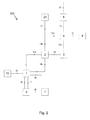
- FIG. 2 An alternative embodiment of a biogas plant 200 according to the invention is in Fig. 2 shown in the plant components of the biogas plant 200, which according to the execution according to Fig. 1 are formed, have the same reference numerals.
- the biogas plant 200 only a single fermentation tank (1) is provided and the second fermentation tank (5) is omitted.
- the structure and the plant operation differ from the above-described embodiment of Fig. 1 merely in that the hydrolyzed digestate, which is cooled in the heat exchanger (2), is passed back into the fermentation tank (1).
- the post-fermentation process then runs in the fermentation tank (1) in the same way as previously described for the fermentation tank (5).
- the separating device (9) receives in the alternative embodiment, the digestate of the fermentation tank (1) via a feed line which connects the fermentation tank (1) with the separating device (9).
Landscapes
- Life Sciences & Earth Sciences (AREA)
- Health & Medical Sciences (AREA)
- Engineering & Computer Science (AREA)
- Chemical & Material Sciences (AREA)
- Organic Chemistry (AREA)
- Zoology (AREA)
- Bioinformatics & Cheminformatics (AREA)
- Wood Science & Technology (AREA)
- Biotechnology (AREA)
- Genetics & Genomics (AREA)
- Molecular Biology (AREA)
- Microbiology (AREA)
- Sustainable Development (AREA)
- Biomedical Technology (AREA)
- Biochemistry (AREA)
- General Engineering & Computer Science (AREA)
- General Health & Medical Sciences (AREA)
- Oil, Petroleum & Natural Gas (AREA)
- General Chemical & Material Sciences (AREA)
- Processing Of Solid Wastes (AREA)
Priority Applications (1)
| Application Number | Priority Date | Filing Date | Title |
|---|---|---|---|
| EP14167591.8A EP2942388A1 (fr) | 2014-05-08 | 2014-05-08 | Procédé de production de biogaz et installation de biogaz |
Applications Claiming Priority (1)
| Application Number | Priority Date | Filing Date | Title |
|---|---|---|---|
| EP14167591.8A EP2942388A1 (fr) | 2014-05-08 | 2014-05-08 | Procédé de production de biogaz et installation de biogaz |
Publications (1)
| Publication Number | Publication Date |
|---|---|
| EP2942388A1 true EP2942388A1 (fr) | 2015-11-11 |
Family
ID=50685774
Family Applications (1)
| Application Number | Title | Priority Date | Filing Date |
|---|---|---|---|
| EP14167591.8A Withdrawn EP2942388A1 (fr) | 2014-05-08 | 2014-05-08 | Procédé de production de biogaz et installation de biogaz |
Country Status (1)
| Country | Link |
|---|---|
| EP (1) | EP2942388A1 (fr) |
Cited By (1)
| Publication number | Priority date | Publication date | Assignee | Title |
|---|---|---|---|---|
| EP3228692A3 (fr) * | 2016-04-04 | 2018-01-10 | SFL Technologies GmbH | Procédé et dispositif de traitement de biomasse |
Citations (4)
| Publication number | Priority date | Publication date | Assignee | Title |
|---|---|---|---|---|
| WO1988004282A1 (fr) * | 1986-12-08 | 1988-06-16 | Waste=Energy Corporation | Procede de restructuration et de conversion de boues |
| WO2006042551A1 (fr) | 2004-10-19 | 2006-04-27 | Bio-Circuit Aps | Installation de production de biogaz a l'aide de l'hydrolyse anaerobie |
| WO2009016082A2 (fr) * | 2007-07-30 | 2009-02-05 | Fraunhofer-Gesellschaft zur Förderung der angewandten Forschung e.V. | Procédé pour convertir de la biomasse constituée de matières premières renouvelables en biogaz dans des fermenteurs anaérobies |
| WO2011095866A2 (fr) * | 2010-02-05 | 2011-08-11 | D.T.A. Srl | Usine de retraitement de boues activées avec récupération d'énergie et de matières brutes secondaires |
-
2014
- 2014-05-08 EP EP14167591.8A patent/EP2942388A1/fr not_active Withdrawn
Patent Citations (4)
| Publication number | Priority date | Publication date | Assignee | Title |
|---|---|---|---|---|
| WO1988004282A1 (fr) * | 1986-12-08 | 1988-06-16 | Waste=Energy Corporation | Procede de restructuration et de conversion de boues |
| WO2006042551A1 (fr) | 2004-10-19 | 2006-04-27 | Bio-Circuit Aps | Installation de production de biogaz a l'aide de l'hydrolyse anaerobie |
| WO2009016082A2 (fr) * | 2007-07-30 | 2009-02-05 | Fraunhofer-Gesellschaft zur Förderung der angewandten Forschung e.V. | Procédé pour convertir de la biomasse constituée de matières premières renouvelables en biogaz dans des fermenteurs anaérobies |
| WO2011095866A2 (fr) * | 2010-02-05 | 2011-08-11 | D.T.A. Srl | Usine de retraitement de boues activées avec récupération d'énergie et de matières brutes secondaires |
Non-Patent Citations (1)
| Title |
|---|
| BRUNI E ET AL: "Comparative study of mechanical, hydrothermal, chemical and enzymatic treatments of digested biofibers to improve biogas production", BIORESOURCE TECHNOLOGY, ELSEVIER BV, GB, vol. 101, no. 22, 1 November 2010 (2010-11-01), pages 8713 - 8717, XP027181704, ISSN: 0960-8524, [retrieved on 20100716] * |
Cited By (1)
| Publication number | Priority date | Publication date | Assignee | Title |
|---|---|---|---|---|
| EP3228692A3 (fr) * | 2016-04-04 | 2018-01-10 | SFL Technologies GmbH | Procédé et dispositif de traitement de biomasse |
Similar Documents
| Publication | Publication Date | Title |
|---|---|---|
| AT506582B1 (de) | Verfahren zur herstellung von biogas | |
| EP1473279A1 (fr) | Appareil et procédé pour la digestion anaérobie de biomasse et la production de biogaz | |
| EP2566946B1 (fr) | Procédé et installation d'exécution de traitement étanche aux gaz par des appareils de percolation dans un procédé de production de biogaz en deux étapes ou plus | |
| EP2707491A2 (fr) | Procédé de production de biogaz à partir d'excréments essentiellement animaux | |
| DE102009035875A1 (de) | Verfahren zur Herstellung von Bio- oder Klärgas | |
| DE102009009985A1 (de) | Verfahren zur Aufkonzentration von Mikroorganismen in wässrigen Substraten | |
| EP0143149B1 (fr) | Procédé pour la réduction de la teneur en H2S dans les processus de dégradation anaérobie, en particulier dans la digestion de boues | |
| DE102007063091A1 (de) | Hybridfermenter zur Erzeugung von methanreichem Biogas | |
| WO2018138368A1 (fr) | Procédé et dispositif pour produire du biogaz | |
| EP1624051A2 (fr) | Procédé de fermentation de biomasse | |
| EP1769064B1 (fr) | Installation de biogaz pour preparer des gaz contenant du methane | |
| EP0988392B1 (fr) | Procede et dispositif de production de biogaz | |
| EP2942388A1 (fr) | Procédé de production de biogaz et installation de biogaz | |
| DE102012113119A1 (de) | Verfahren sowie Vorrichtung zur Erzeugung regenerativer Energie aus Biomasse | |
| DE102011015611B4 (de) | Verfahren zur Erzeugung von Biogas aus organischen Substraten | |
| EP3066205B1 (fr) | Procédé de production de biogaz comprenant une réduction de la concentration en ammonium en utilisant l'anammox | |
| EP1676819B1 (fr) | Procédé pour le traitement des boues organiques sans danger pour l'environnement et station d'épuration des eaux | |
| DE102013108264B4 (de) | Biogaseinrichtung | |
| EP3017052B1 (fr) | Procédé d'initialisation du processus de fermentation dans des installations de production de biogaz | |
| DE102011008186B4 (de) | Verfahren zur Herstellung von Biogas aus überwiegend stärkehaltigen Rohstoffen als Biomasse | |
| EP3967761B1 (fr) | Procédé de génération d'un gaz enrichi en méthane | |
| EP1362924B1 (fr) | Procédé pour actionner les équipements méthane-producteurs ou méthane-contenants, en particulier les équipements de biogas ou les tubes contenant le biogas | |
| DE102021101167A1 (de) | Verfahren und Vorrichtung zur Verwertung von organischen Materialien | |
| EP2960324B1 (fr) | Procede de production de biogaz dans un fermenteur et dispositif d'execution du procede | |
| CH707254A2 (de) | Biogasanlage. |
Legal Events
| Date | Code | Title | Description |
|---|---|---|---|
| PUAI | Public reference made under article 153(3) epc to a published international application that has entered the european phase |
Free format text: ORIGINAL CODE: 0009012 |
|
| AK | Designated contracting states |
Kind code of ref document: A1 Designated state(s): AL AT BE BG CH CY CZ DE DK EE ES FI FR GB GR HR HU IE IS IT LI LT LU LV MC MK MT NL NO PL PT RO RS SE SI SK SM TR |
|
| AX | Request for extension of the european patent |
Extension state: BA ME |
|
| 17P | Request for examination filed |
Effective date: 20160511 |
|
| RBV | Designated contracting states (corrected) |
Designated state(s): AL AT BE BG CH CY CZ DE DK EE ES FI FR GB GR HR HU IE IS IT LI LT LU LV MC MK MT NL NO PL PT RO RS SE SI SK SM TR |
|
| 17Q | First examination report despatched |
Effective date: 20181206 |
|
| STAA | Information on the status of an ep patent application or granted ep patent |
Free format text: STATUS: THE APPLICATION IS DEEMED TO BE WITHDRAWN |
|
| 18D | Application deemed to be withdrawn |
Effective date: 20190417 |