EP2941946A1 - Unité de guidage pour produits agricoles destinée à un dispositif servant à récolter les produits agricoles et dispositif comprenant l'unité de guidage - Google Patents
Unité de guidage pour produits agricoles destinée à un dispositif servant à récolter les produits agricoles et dispositif comprenant l'unité de guidage Download PDFInfo
- Publication number
- EP2941946A1 EP2941946A1 EP15166394.5A EP15166394A EP2941946A1 EP 2941946 A1 EP2941946 A1 EP 2941946A1 EP 15166394 A EP15166394 A EP 15166394A EP 2941946 A1 EP2941946 A1 EP 2941946A1
- Authority
- EP
- European Patent Office
- Prior art keywords
- pick
- supporting body
- guiding
- guiding element
- guiding unit
- Prior art date
- Legal status (The legal status is an assumption and is not a legal conclusion. Google has not performed a legal analysis and makes no representation as to the accuracy of the status listed.)
- Granted
Links
- 238000003306 harvesting Methods 0.000 title claims description 29
- 230000007246 mechanism Effects 0.000 claims description 14
- 244000025254 Cannabis sativa Species 0.000 claims description 3
- 239000010902 straw Substances 0.000 claims description 3
- 241000196324 Embryophyta Species 0.000 claims description 2
- 230000000694 effects Effects 0.000 description 3
- 210000001520 comb Anatomy 0.000 description 2
- 230000008878 coupling Effects 0.000 description 1
- 238000010168 coupling process Methods 0.000 description 1
- 238000005859 coupling reaction Methods 0.000 description 1
- 125000004122 cyclic group Chemical group 0.000 description 1
- 238000009434 installation Methods 0.000 description 1
- 230000001788 irregular Effects 0.000 description 1
- 230000007257 malfunction Effects 0.000 description 1
- 230000000630 rising effect Effects 0.000 description 1
- 238000012216 screening Methods 0.000 description 1
Images

Classifications
-
- A—HUMAN NECESSITIES
- A01—AGRICULTURE; FORESTRY; ANIMAL HUSBANDRY; HUNTING; TRAPPING; FISHING
- A01D—HARVESTING; MOWING
- A01D57/00—Delivering mechanisms for harvesters or mowers
- A01D57/20—Delivering mechanisms for harvesters or mowers with conveyor belts
-
- A—HUMAN NECESSITIES
- A01—AGRICULTURE; FORESTRY; ANIMAL HUSBANDRY; HUNTING; TRAPPING; FISHING
- A01D—HARVESTING; MOWING
- A01D84/00—Haymakers not provided for in a single one of groups A01D76/00 - A01D82/00
-
- A—HUMAN NECESSITIES
- A01—AGRICULTURE; FORESTRY; ANIMAL HUSBANDRY; HUNTING; TRAPPING; FISHING
- A01D—HARVESTING; MOWING
- A01D89/00—Pick-ups for loaders, chaff-cutters, balers, field-threshers, or the like, i.e. attachments for picking-up hay or the like field crops
- A01D89/006—Accessories
- A01D89/008—Devices cooperating with the pick-up
Definitions
- This invention relates to a guiding unit for agricultural products for a device for harvesting the agricultural products and a device for harvesting agricultural products comprising the guiding unit.
- This invention is thus applied in particular in the agricultural sector, in particular in the harvesting of products performed immediately after the cutting (or mowing), or in a subsequent step.
- Harvesting devices are normally used for picking up from the ground grass, straw, hay (also cut by other machines) or for picking up pulses and, in any case, for picking up similar agricultural products (usually plants), with a long shape.
- a pulling vehicle such as a tractor or a self-propelled agricultural machine
- a pulling vehicle such as a tractor or a self-propelled agricultural machine
- Prior art harvesting devices have a main axis of extension which, during use, remains transversal to the axis of movement of the pulling vehicle.
- harvesting devices use a plurality of harvesting elements associated therewith and driven by a movement system.
- the movement system is generally driven by a Cardan joint or the like which, through a power take-off, draws drive power from the engine of the pulling vehicle.
- Each pick-up element is in turn provided with one or more juxtaposed tines.
- the pick-up elements (and the related tines) are usually positioned around the preferred axis of extension along rows parallel with the preferred axis of extension.
- Each pick-up element (and the related tines) is moved by the movement system along a closed trajectory surrounding the preferred axis of extension.
- the tines are straight elements with one end coupled (either directly or by means of parts of the respective pick-up element) to the movement system and the other end free.
- devices of this type Operatively downstream of the pick-up elements, devices of this type generally also comprise means for unloading the agricultural products harvested, usually consisting of movement devices, such as conveyor belts, chain conveyors or screw conveyors, located along the axis of extension of the pick-up device immediately downstream of the pick-up elements, in order to transport the agricultural products to the sides of the pulling vehicle.
- movement devices such as conveyor belts, chain conveyors or screw conveyors
- each of the unloading means has a respective axis of movement, generally parallel to the main line of the frame, that is, transversal to the advancing axis.
- the products harvested tend to accumulate at the pick-up means, making the outfeed flow from the unloading means irregular and, in any case, causing problems linked to the clogging of the movement zones.
- This may actually block the device or form piles with inconstant volumes, which may disturb the pick-up operation.
- patent document EP2037727 illustrates a guiding unit defined by a pair of arms pivoted to the frame of the device in such a way as to surmount the unloading means and provided, at their ends, with an array of combs which, in use, are facing the pick-up tines in such a way as to compact the products picked up, thus facilitating the harvesting.
- the arms are connected to the frame, at the rear of it, through a four-bar linkage which allows the inclination to be varied as a function of the quantity of products to be picked up.
- this solution is complex from the constructional viewpoint since it requires the replacement of various components of the frame of the device and the design of structurally complex joints.
- the rotational movement of the guiding unit about a horizontal axis located to the rear of the unloading means does not allow a precise modulation of its action, since a rotation of the arm, even minimal, results in a very substantial translation of the combs.
- the aim of this invention is therefore to provide a guiding unit for agricultural products for a device for picking up the agricultural products and a device for picking up the agricultural products which is able to overcome the drawbacks of the prior art.
- the aim of this invention is to provide a guiding unit for agricultural products with high performance levels and ease of installation in a device for picking up the agricultural products.
- the aim of this invention is to provide a device for picking up agricultural products with high performance levels and which is able to adapt to the flow of the products to be collected.
- a guiding unit for agricultural products for a device for picking up the agricultural products of the type comprising a frame extending along a main line, pick-up means associated with the frame and unloading means positioned operatively downstream of the pick-up means and movable along the main line
- the guiding unit comprises a supporting body connectable to the frame of the pick-up device and provided with a supporting portion which, during use, is located above the unloading means, a guiding element extending mainly along the operating direction and delimited, transversally to the operating direction, by an upper longitudinal edge, proximal to the supporting body, and by a lower longitudinal edge, distal from the supporting body and, in use, opposite and in front of the pick-up means in such a way as to delimit a pass-through section for the products to be harvested, guiding them.
- the guiding element comprises connecting means operatively interposed between the guiding element and the supporting portion of the supporting body, designed to allow a translation of the guiding element towards and away from the supporting body.
- the connecting means are fixed to the upper longitudinal edge of the guiding element.
- the connecting means are designed to constrain the guiding element to move towards and away from the supporting body in a single sliding plane.
- the guiding element translates in a "front" plane, that is, transversal to the feed direction making it more easy to control its movement, and more easy to adjust the flow of products.
- the guiding unit is movable, in roto-translation, in a plane transversal to the feed direction, preferably inclined relative to a horizontal plane for supporting the device.
- the guiding element can be translated both after a vertical action, performed by the products picked up by the pick-up means, and after a horizontal action.
- the connecting means comprise a first and a second elbow-style kinematic mechanism spaced from each other along the operating direction, each connected to a half-part of the guiding element to allow a roto-translation relative to the supporting body.
- the guiding element is connected to the supporting body in such a way that it can both oscillate rigidly towards and away from the guiding element and tilt, varying its inclination, in the sliding plane, relative to the supporting body.
- the guiding unit is able to adapt to the various operating conditions, varying the position of the guiding element relative to the supporting body in a localised manner, that is, adapting the inclination of the guiding element as a function of the quantity of products in the various pick-up zones.
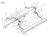
- the numeral 1 denotes a guiding unit for a device 100 for harvesting agricultural products, preferably fine-stemmed and longitudinal products, such as, for example, grass, straw, hay or for harvesting pulses.
- the harvesting device 100 is of the type which can be moved by a movement (or pulling) vehicle along a path on which a multitude of long, and preferably thin, agricultural products lie, the harvesting device 100 being designed to lift them from the ground using pick-up means 102 and to transport them on specific unloading means or into a receiving chamber by means of a specific movement system.
- the device comprises a frame 101 extensing along a main axis of extension "A" which, during use, remains transversal to the axis of movement (or of advancing) of the pulling vehicle.
- the frame preferably comprises coupling means (not illustrated) by which it is connected to the pulling vehicle and protruding transversely (preferably at right angles) to the direction of extension "A".
- the device 100 comprises pick-up means 102 for harvesting the agricultural products.
- the pick-up means 102 comprise a plurality of rotatable pick-up elements 102a, each in turn equipped with at least one long harvesting tine.
- pick-up elements 102a are arranged in succession along the main line "A" (and spaced, preferably equispaced, from each other).
- the pick-up elements 102a are arranged along the extension of the device, thereby increasing the working portion thereof.
- the tines are arranged around the same central axis of rotation, oriented radially thereto in spoke-like fashion.
- the harvesting device 100 comprises a movement system for moving each of the pick-up elements 102a along a closed path surrounding the main line "A" (corresponding to the aforementioned central axis).
- the product harvesting axis is transversal, preferably at right angles, to the main line "A".
- the closed path comprises a transporting stretch along which the agricultural product is transported between a pickup point where the product is lifted from the ground by the long tines and a release point where the agricultural product is disengaged from the tines.
- the harvesting device 100 also comprises a plurality of bands 104 fixed to the frame 101, juxtaposed along the main line "A" and spaced from each other in such a way that each pick-up element 102a is at least partly interposed between two consecutive bands 104.
- the bands 104 are defined by curved members shaped in such a way as to surround the main line "A" at least at the forward stroke of the tines (that is, the closed path).
- the harvesting device 100 comprises agricultural product unloading means 106 located downstream of the pick-up means 102 (more specifically, downstream of the release point), configured to transport the agricultural products and release them at the sides (or, if necessary, at the back) of the pulling vehicle.
- the main line "A" is a direction of movement of the unloading means 106. This direction is transversal, preferably at right angles, to the harvesting direction described above.
- the direction "A" denotes both the direction of extension and the direction of movement.
- the unloading means 106 form a supporting surface "B" for the agricultural products harvested and are mobile along the main line "A" to release the agricultural products to the sides of the pulling vehicle.
- the device 100 (and more specifically, the unloading means 106) comprises a conveyor belt 106a operatively located downstream of the pick-up means 102 and forming a supporting surface "B" for the agricultural products transported by the conveyor unit 1.
- the conveyor belt 106a forms a supporting surface "B" which is mobile along the axis "A" to release the agricultural products to the sides of the pulling vehicle.
- the conveyor belt could be replaced by any cyclic movement apparatus capable of defining a mobile supporting surface for the products, such as, for example, a chain conveyor, a track conveyor or the like.
- the unloading means might be defined by more aggressive means, such as a screw feeder or the like.
- the device comprises a unit 1 for guiding the agricultural products, associated with the frame 101 and operating at the pick-up means 102.
- the guiding unit 1 can be preferably associated with the frame 101 in a removable fashion, that is, it can be both integrated in the device 1 and marketed as an accessory element.
- the guiding unit 1 comprises a supporting body 2 connected to the frame 101 of the harvesting device 100 and provided with a supporting portion 2a which, during use, is located above the unloading means 106.
- the supporting body 2 extends at least in part above the unloading means 106, at a predetermined distance from them.
- the supporting portion 2a is situated at a greater height than the supporting surface "B," at a predetermined distance from it.
- the supporting body 2 is over the unloading means 106 and the supporting portion 2a is positioned above a half-part of the unloading means 106 proximal to the pick-up means 102.
- This half-part is measured with reference to a middle axis of the unloading means 106 which is oriented along (that is, parallel to) the main line "A".
- the frame 101 comprises at least one rear element 101 a, positioned on the opposite side of the unloading means 106 relative to the pick-up means 102.
- the unloading means 106 extend along the main line “A" along two edges "E1," “E2,” wherein a first edge “E1” is facing the rear element 101 a of the frame 101 and a second edge “E2" is facing the pick-up means 102.
- the rear element 101 a of the frame 101 is equipped with at least one a free end, projecting above the unloading means 106.
- the rear element 101 a is protruding above the supporting surface "B", that is, it rises away from it.
- the supporting body 2 comprises at least a bar 3 extending above the unloading means 106 (that is, of the supporting surface "B") between its own first end 3a, rigidly constrained to the free end of the rear element 101 a, and a second end 3b forming the supporting portion 2a.
- the bar 3 is positioned in a cantilever fashion relative to the rear element 101 a of the frame 101.
- the supporting body 2 comprises a plurality of bars 3, preferably two, positioned in succession, that is, spaced from each other, along the main line "A".
- the supporting body 2 comprises a covering element 21 extending between the bars 3 and opposite the unloading means 106.
- the guiding unit 1 comprises adjustment means 4 interposed between the rear portion 101 a of the frame 101 and the supporting body 2.
- the adjustment means 4 are operatively interposed between the rear portion 101 a of the frame 101 and the bar 3 (that is, the bars 3).
- the adjustment means 4 are designed to allow the setting of the angle delimited between the rear portion 101 a and the bar 4.
- the adjustment means 4 comprise a pair of slidably associated bodies and an adjusting pin designed to lock the relative sliding between the bodies in a predetermined angular position.
- the guiding unit 1 also comprises a guiding element 5 extending mainly along the main line "A" and delimited, transversally to it, by an upper longitudinal edge 5a, proximal to the supporting body 2, and by a lower longitudinal edge 5b, distal from the supporting body 2.
- the guiding element 5 extends along the main line "A" (that is, parallel to it) between two longitudinal edges, upper 5a and lower 5b.
- the longitudinal edge 5b is opposite and in front of the pick-up means 102 in such a way as to delimit a pass-through section for the products to be harvested, guiding them.
- the lower edge 5b of the guiding element 5 is located at a distance from the pick-up means such as to define (and delimit) the space for transit of the agricultural products.
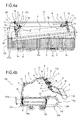
- the guiding element 5 is provided, at its lower longitudinal edge 5b, with an active portion 6 having a weight such that, in the absence of external forces, it keeps the guiding element close to the pick-up means 102 (that is, in a position away from the supporting body 2).
- the active portion is defined by a tubular body 6a or by a bar extending along the main line "A" and defining the lower longitudinal edge 5b of the guiding element 5.
- the active portion could be defined by a roller or by a grille.
- the guiding element 5 comprises at least one panel 7 extending along the main line "A” and delimited, transversally to the main line "A", by the upper longitudinal edge 5a and by the lower longitudinal edge 5b.
- the guiding element 5 is defined by a panel 7 or covering element extending between the upper longitudinal edge 5a, connected to the supporting body 2, and the lower longitudinal edge 5b, defined by the active portion 6.
- the panel 7 has, near to the lower longitudinal edge 5b, a concavity oriented towards the pick-up means 102, in order to follow a curved path which the products move along on the pick-up means 102.
- the panel 7, near to the lower longitudinal edge 5b, has a concavity oriented towards the pick-up means 102 in order to follow the movement of the pick-up elements 102a.
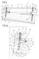
- the guiding unit 1 comprises connecting means 8 operatively interposed between the guiding element 5 and the supporting portion 2a of the supporting body 2.
- the connecting means 8 are fixed in the proximity of the upper longitudinal edge 5a of the guiding element 5.
- These connecting means 8 are designed to allow a translation of the guiding element 5 towards and away from the supporting body 2.
- the guiding element 5 is movable towards and away from the supporting body 2 to define, respectively, up and down movements depending on the quantity of products to be harvested, for guiding their flow on the pick-up means 102.
- the guiding element 5 is simple to construct and to install, and at the same time the translating movement allows a precise adjustment of the space for transit of the products.
- the connecting means 8 are designed to constrain the guiding element 5 to move towards and away from the supporting body in a single sliding plane "P".
- the connecting means 8 are designed to allow translation of the guiding element 5 in a sliding plane "P" which is set at an angle to a vertical direction.
- the guiding element 5 and the connecting means 8 are designed to allow a translation of the guiding element 5 in the sliding plane following both a pushing action performed by the products on the pick-up means (substantially vertical) and a pushing action performed horizontally on the lower longitudinal edge 5b.
- the sliding plane "P" is set at an angle, relative to a vertical direction, of between -70° and +45°.
- the preferred angle of inclination is between -40° and -20°.
- adjusting units designed to allow the setting of a predetermined inclination of the sliding plane "P," that is, a predetermined inclination between the supporting body 2 and the guiding element 5.
- the connecting means 8 comprise at least first connecting means 9 and second connecting means 10 both interposed between the supporting body 2 and the guiding element 5.
- the first 9 and second 9 connecting means are spaced from each other along the main line "A".
- first connecting means 9 and the second connecting means 10 being movable independently of one another between a contracted position and an extended position for allowing a roto-translation of the guiding element 5 relative to the supporting body 2.
- the guiding unit 1 is able to adapt to the different flow conditions of the products at the two sides of the device.
- first 9 and second 10 connection means are preferably connected to two separate half-parts of the guiding element 5, located on opposite sides of a median line of the device 1 at right angles to the main line "A.”
- first connecting means 9 and second connecting means 10 are connected to the supporting body 2 and to the guiding element 5 at respective joint points "G".
- the connecting means 8 (that is, both the first 9 and second 10 connecting means) comprise at least a first arm 12 pivoting at the supporting body 2 at a first pin 13 and a second arm 14 pivoting at the guiding element 5 at a second pin 15.
- first pin 13 and the second pin 15 define the joint points "G" mentioned above.
- first arm 12 and second arm 14 are rotatably connected to one another at a third pin 16 for forming an elbow-style kinematic mechanism 17a, 17b in which the arms 12, 14 are rotatably movable between a closed position and an open position.
- first pin 13, second pin 15 and third pin 16 define axes of rotation "C" which are substantially parallel to one another and orthogonal to a plane of movement "P" of the guiding element 5.
- the connecting means 8 comprise two elbow-style kinematic mechanisms 17a, 17b, each forming, respectively, the first 9 and the second 10 connecting means.
- the connecting means 8 comprise a first 17a and a second elbow-style kinematic mechanism 17a.
- each elbow-style kinematic mechanism 17a, 17b is connected to a different half-part of the guiding element 5 for allowing a roto-translation (in the sliding plane "P") relative to the supporting body 2.
- the elbow-style kinematic mechanisms 17a, 17b are oriented towards each other.
- the third pins 16 are proximal to each other relative to the first 13 and second 15 pins.
- each elbow-style kinematic mechanism 17a, 17b comprises at least one locking body 18 operatively interposed between the first arm 9 and the second arm 10 for limiting the opening of the first arm 12 and the second arm 14 to a predetermined angular value.
- the locking element 18 is designed to limit the distance between the guiding element 5 and the supporting body 2 in the far position.
- the locking body 18 is defined by a pin or split pin 18a which can be inserted in the first arm 12 or second arm 14 and which can come into abutment respectively with the second arm 14 or with the first arm 12 in the open position (corresponding to the extended position of the first 9 and second 10 connecting means).
- the first arm 12 or the second arm 14 is equipped with a plurality of seats 18b which can be coupled with the split pin 18a to allow an adjustment of the opening stroke between the arms 12, 14.
- the first connecting means 9 are provided with at least one constraining element 11 designed to keep linear the relative movement of its joint points "G" during the movement between the contracted position and the extended position.
- one of the elbow-style kinematic mechanisms 17a (that is, the first) comprises at least a rod 19 extending between a first end 19a connected to the guiding element 5 and a second end 19b connected to the first arm 12 for constraining the movement of the second pin 15 relative to the first pin 13 limiting their offset.
- the rod 19 defines at least partly the constraining element 11.
- the connecting means 8 comprise a piston (not illustrated) operatively interposed between the first arm 12 and the second arm 14 of at least one elbow-style kinematic mechanism 17a, 17b, preferably of both.
- the piston (preferably of a pneumatic or hydraulic type) is designed to contribute to the movement from the open position to the closed position.
- the piston acts as an auxiliary actuator during the rising of the guiding element 5.
- the piston is designed to oppose the lowering of the guiding element 5, that is, the opening of the elbow-style kinematic mechanism 17a, 17b.
- this reduces the impacts and the stress on the pins, increasing the working life of the guiding unit 1.
- the guiding element 5 is modularly disconnectable from the supporting body 2.
- the third pins 13 are removable to allow an uncoupling between the guiding element 5 and the supporting body 2.
- the operator if it is not used, remove the guiding element 5 (and the connecting means 8), keeping solely the supporting body 2 anchored to the frame of the device 100.
- the supporting body 2 comprises the covering element 21
- this allows the operator to unlink the screening function of the covering element 21 from that of guiding the guiding element 5.
- the invention achieves the preset aims and brings major advantages.
- a slidable guiding element preferably in a single plane, during raising and lowering, allows a more effective and simple adjustment of the action of the products.
- the presence of at least two connecting units movable independently of each other allows a roto-translation of the guiding element, preferably a panel, in the sliding plane, which makes the guiding unit even more functional and high performing.
Landscapes
- Life Sciences & Earth Sciences (AREA)
- Environmental Sciences (AREA)
- Chain Conveyers (AREA)
Priority Applications (2)
| Application Number | Priority Date | Filing Date | Title |
|---|---|---|---|
| SI201530407T SI2941946T1 (sl) | 2014-05-05 | 2015-05-05 | Vodilna enota za kmetijske proizvode za pobiralno napravo pri spravilu navedenih kmetijskih proizvodov in pobiralna naprava, ki vsebuje vodilno enoto |
| PL15166394T PL2941946T3 (pl) | 2014-05-05 | 2015-05-05 | Jednostka prowadząca dla produktów rolnych do urządzenia zbierającego do zbierania produktów rolnych i urządzenie zbierające zawierające jednostkę prowadzącą |
Applications Claiming Priority (1)
| Application Number | Priority Date | Filing Date | Title |
|---|---|---|---|
| ITBO20140260 | 2014-05-05 |
Publications (2)
| Publication Number | Publication Date |
|---|---|
| EP2941946A1 true EP2941946A1 (fr) | 2015-11-11 |
| EP2941946B1 EP2941946B1 (fr) | 2018-07-04 |
Family
ID=51220634
Family Applications (1)
| Application Number | Title | Priority Date | Filing Date |
|---|---|---|---|
| EP15166394.5A Active EP2941946B1 (fr) | 2014-05-05 | 2015-05-05 | Unité de guidage pour produits agricoles destinée à un dispositif servant à récolter les produits agricoles et dispositif comprenant l'unité de guidage |
Country Status (4)
| Country | Link |
|---|---|
| US (1) | US9521807B2 (fr) |
| EP (1) | EP2941946B1 (fr) |
| PL (1) | PL2941946T3 (fr) |
| SI (1) | SI2941946T1 (fr) |
Cited By (2)
| Publication number | Priority date | Publication date | Assignee | Title |
|---|---|---|---|---|
| EP3516941A1 (fr) * | 2018-01-29 | 2019-07-31 | MacDon Industries Ltd. | Connexion des extrémités du convoyeur de tuloteuse d'une tête de récolte |
| EP3666059A1 (fr) * | 2018-12-10 | 2020-06-17 | PÖTTINGER Landtechnik GmbH | Machine agricole de récolte |
Families Citing this family (4)
| Publication number | Priority date | Publication date | Assignee | Title |
|---|---|---|---|---|
| US9878848B2 (en) * | 2015-09-11 | 2018-01-30 | Mgs Machine Corporation | Friction feeder |
| DE202018107313U1 (de) | 2018-12-20 | 2020-03-23 | Pöttinger Landtechnik Gmbh | Landwirtschaftliche Erntemaschine |
| US12089536B2 (en) * | 2020-05-19 | 2024-09-17 | Cnh Industrial America Llc | Agricultural vehicle with retainer for blockage removing windguard |
| DE202022105171U1 (de) | 2022-09-14 | 2023-12-19 | Pöttinger Landtechnik Gmbh | Landwirtschaftliche Erntemaschine |
Citations (4)
| Publication number | Priority date | Publication date | Assignee | Title |
|---|---|---|---|---|
| EP2037727A1 (fr) | 2006-06-30 | 2009-03-25 | Kuhn S.A. | Machine agricole pour la recolte des fourrages |
| US20120023884A1 (en) * | 2010-07-28 | 2012-02-02 | Biolink J.V. | Biomass handling and processing |
| DE102012011591A1 (de) * | 2012-06-13 | 2013-12-19 | Claas Saulgau Gmbh | Aufnahmevorrichtung für eine landwirtschaftliche Erntemaschine |
| EP2689653A1 (fr) * | 2012-07-27 | 2014-01-29 | CNH Belgium N.V. | Mécanisme coupe-vent de ramassage pour machine agricole |
Family Cites Families (36)
| Publication number | Priority date | Publication date | Assignee | Title |
|---|---|---|---|---|
| US2524233A (en) * | 1941-04-19 | 1950-10-03 | Case Co J I | Pickup device for balers |
| US2362861A (en) * | 1941-04-19 | 1944-11-14 | Case Co J I | Baler |
| US2571489A (en) * | 1944-06-16 | 1951-10-16 | Case Co J I | Baling machine with spiral feeding and compression means |
| US2647355A (en) * | 1949-03-05 | 1953-08-04 | Massey Harris Co Ltd | Pickup baler |
| US2872772A (en) * | 1951-10-30 | 1959-02-10 | Sperry Rand Corp | Adjustable wind-guard for baler pick-up |
| US2691266A (en) * | 1953-03-23 | 1954-10-12 | Volk | Wind guard attachment for pickup devices |
| US3788053A (en) * | 1972-05-30 | 1974-01-29 | C Bonnett | Windrow controller |
| US3815344A (en) * | 1972-11-29 | 1974-06-11 | Lowell R | Machine for forming large round bales of a fibrous material |
| US3815346A (en) * | 1973-06-01 | 1974-06-11 | Deere & Co | Harvester pickup |
| US3924391A (en) * | 1975-03-03 | 1975-12-09 | Deere & Co | Adjustable crop compressor for a pickup mechanism |
| DD139380A1 (de) * | 1978-06-20 | 1980-01-02 | Spaida Hans Peter | Aufnahmeeinrichtung fuer halmfuttererntemaschinen |
| US4304090A (en) * | 1980-02-11 | 1981-12-08 | Gavrilenko Boris P | Pickup of an agricultural machine |
| NL8003794A (nl) * | 1980-07-01 | 1982-02-01 | Multinorm Bv | Inrichting voor het van het land opnemen van gewas. |
| US4411127A (en) * | 1982-04-05 | 1983-10-25 | Sperry Corporation | Floating windguard |
| US4495756A (en) * | 1983-08-15 | 1985-01-29 | Sperry Corporation | Pickup attachment for harvesting machines |
| US4516389A (en) * | 1984-09-04 | 1985-05-14 | Core Grant M | Round hay baling machine |
| US4905466A (en) * | 1988-08-12 | 1990-03-06 | Alden Heppner | Windrow mover |
| US4981013A (en) * | 1989-08-21 | 1991-01-01 | Underwood Chester E | Corn harvesting apparatus |
| GB9903624D0 (en) * | 1999-02-18 | 1999-04-07 | Ford New Holland Nv | Movable windguard |
| US6688092B2 (en) * | 2002-01-14 | 2004-02-10 | Deere & Company | Pick-up crop baffle including integral crop hold down rods and suspension for use in widely varied crops |
| US6810650B2 (en) * | 2002-03-28 | 2004-11-02 | New Holland North America, Inc. | Replaceable windguard tines for a round baler |
| US6935094B1 (en) * | 2004-04-15 | 2005-08-30 | Cnh America Llc | Wind guard latch retainer |
| US6877304B1 (en) * | 2004-07-31 | 2005-04-12 | Cnh America Llc | Windguard for round baler |
| US6962041B1 (en) * | 2004-07-31 | 2005-11-08 | Cnh America Llc | Windguard for round baler including float arms |
| US7107748B2 (en) * | 2004-07-31 | 2006-09-19 | Cnh America Llc | Agricultural implement pickup |
| US20060277889A1 (en) * | 2005-06-10 | 2006-12-14 | Sheedy Ronald L | Wind screen hold down attachment |
| US7617662B2 (en) * | 2005-06-14 | 2009-11-17 | Deere & Company | Integrated crop baffle and hold-down assembly used with baler pick-up and suspension for same |
| US7448196B2 (en) * | 2007-01-05 | 2008-11-11 | Agco Corporation | Baler with multi-auger pickup |
| US7650741B2 (en) * | 2007-01-05 | 2010-01-26 | Agco Corporation | Articulating windguard for agricultural baler |
| US20090100814A1 (en) * | 2007-10-22 | 2009-04-23 | Philip Egging | Non-Powered Roller for Assisting Crop Pick-Up With a Baler |
| US7654069B1 (en) * | 2008-12-10 | 2010-02-02 | Vermeer Manufacturing Co. | Baler slider frame for mounting accessories to a crop pickup device |
| US8051634B2 (en) * | 2010-01-19 | 2011-11-08 | Cnh America Llc | Replaceable guide assembly tines for an agricultural harvester |
| BE1020227A3 (nl) * | 2011-10-10 | 2013-06-04 | Cnh Belgium Nv | Opraapeenheid met beweegbaar windscherm. |
| FR2999868B1 (fr) * | 2012-12-20 | 2014-12-12 | Kuhn Sa | Machine agricole de recolte comportant un dispositif de guidage perfectionne des vegetaux |
| US9681603B2 (en) * | 2013-03-15 | 2017-06-20 | Cnh Industrial America Llc | Cam action windguard |
| DE202014003637U1 (de) * | 2014-04-29 | 2015-07-30 | Alois Pöttinger Maschinenfabrik Gmbh | Landwirtschaftliche Maschine |
-
2015
- 2015-05-04 US US14/703,268 patent/US9521807B2/en active Active
- 2015-05-05 PL PL15166394T patent/PL2941946T3/pl unknown
- 2015-05-05 EP EP15166394.5A patent/EP2941946B1/fr active Active
- 2015-05-05 SI SI201530407T patent/SI2941946T1/sl unknown
Patent Citations (4)
| Publication number | Priority date | Publication date | Assignee | Title |
|---|---|---|---|---|
| EP2037727A1 (fr) | 2006-06-30 | 2009-03-25 | Kuhn S.A. | Machine agricole pour la recolte des fourrages |
| US20120023884A1 (en) * | 2010-07-28 | 2012-02-02 | Biolink J.V. | Biomass handling and processing |
| DE102012011591A1 (de) * | 2012-06-13 | 2013-12-19 | Claas Saulgau Gmbh | Aufnahmevorrichtung für eine landwirtschaftliche Erntemaschine |
| EP2689653A1 (fr) * | 2012-07-27 | 2014-01-29 | CNH Belgium N.V. | Mécanisme coupe-vent de ramassage pour machine agricole |
Cited By (2)
| Publication number | Priority date | Publication date | Assignee | Title |
|---|---|---|---|---|
| EP3516941A1 (fr) * | 2018-01-29 | 2019-07-31 | MacDon Industries Ltd. | Connexion des extrémités du convoyeur de tuloteuse d'une tête de récolte |
| EP3666059A1 (fr) * | 2018-12-10 | 2020-06-17 | PÖTTINGER Landtechnik GmbH | Machine agricole de récolte |
Also Published As
| Publication number | Publication date |
|---|---|
| US20150313082A1 (en) | 2015-11-05 |
| PL2941946T3 (pl) | 2019-01-31 |
| EP2941946B1 (fr) | 2018-07-04 |
| US9521807B2 (en) | 2016-12-20 |
| SI2941946T1 (sl) | 2018-11-30 |
Similar Documents
| Publication | Publication Date | Title |
|---|---|---|
| EP2941946B1 (fr) | Unité de guidage pour produits agricoles destinée à un dispositif servant à récolter les produits agricoles et dispositif comprenant l'unité de guidage | |
| US9750187B2 (en) | Adjustable row unit deck plate for a header of an agricultural harvester | |
| EP2420128B1 (fr) | Commande de courroie de convoyeur flexible pour moissonneuse agricole | |
| EP3440919A1 (fr) | Support de bras de flotteur | |
| DK2839731T3 (en) | Green fodder harvesting machine | |
| CA3000273C (fr) | Dispositif de recolte de cereales a tiges comprenant des plaques de cueillette mobiles | |
| EP2777379B1 (fr) | Pare-vent à action de came | |
| US8616812B2 (en) | Header trailer | |
| CN112867390B (zh) | 用于掘起根茎类作物的掘起设备 | |
| DK2939521T3 (en) | Agriculture machine | |
| US8109070B1 (en) | Dual windrow crop inverting and combining apparatus and method | |
| US9615513B2 (en) | Harvester pick-up support | |
| BR112017007370B1 (pt) | Conjunto separador de pedra para uma colheitadeira | |
| BE1026187B1 (de) | Auswurfanordnung zur Anbringung am Ende einer Austrageinrichtung | |
| JP6436884B2 (ja) | 収穫機 | |
| US20200275609A1 (en) | Cam Track Adjustment Assembly for a Harvesting Reel | |
| EP3058805B1 (fr) | Faneuse | |
| EP1595434B1 (fr) | Agencement de rabatteur | |
| EP3669638A1 (fr) | Engin d'abattage-façonnage agricole | |
| EP3659421A1 (fr) | Tête de récolte dotée de vis sans fin transversale réglable | |
| JPH10313634A (ja) | 農産物収穫機における収穫物搬送装置 | |
| BR112021015451A2 (pt) | Conjunto de carretel de uma plataforma agrícola | |
| JP2010104258A (ja) | 自脱型コンバイン | |
| EP4282247A1 (fr) | Séquence de capture de grain de tournière pour tête de véhicule agricole | |
| CA3240354A1 (fr) | Accessoire de ramassage pour une moissonneuse |
Legal Events
| Date | Code | Title | Description |
|---|---|---|---|
| PUAI | Public reference made under article 153(3) epc to a published international application that has entered the european phase |
Free format text: ORIGINAL CODE: 0009012 |
|
| AK | Designated contracting states |
Kind code of ref document: A1 Designated state(s): AL AT BE BG CH CY CZ DE DK EE ES FI FR GB GR HR HU IE IS IT LI LT LU LV MC MK MT NL NO PL PT RO RS SE SI SK SM TR |
|
| AX | Request for extension of the european patent |
Extension state: BA ME |
|
| 17P | Request for examination filed |
Effective date: 20160511 |
|
| RBV | Designated contracting states (corrected) |
Designated state(s): AL AT BE BG CH CY CZ DE DK EE ES FI FR GB GR HR HU IE IS IT LI LT LU LV MC MK MT NL NO PL PT RO RS SE SI SK SM TR |
|
| RIN1 | Information on inventor provided before grant (corrected) |
Inventor name: UBALDI, RAFFAELE |
|
| REG | Reference to a national code |
Ref country code: DE Ref legal event code: R079 Ref document number: 602015012899 Country of ref document: DE Free format text: PREVIOUS MAIN CLASS: A01D0084000000 Ipc: A01D0089000000 |
|
| GRAP | Despatch of communication of intention to grant a patent |
Free format text: ORIGINAL CODE: EPIDOSNIGR1 |
|
| STAA | Information on the status of an ep patent application or granted ep patent |
Free format text: STATUS: GRANT OF PATENT IS INTENDED |
|
| RIC1 | Information provided on ipc code assigned before grant |
Ipc: A01D 84/00 20060101ALI20171208BHEP Ipc: A01D 57/20 20060101ALI20171208BHEP Ipc: A01D 89/00 20060101AFI20171208BHEP |
|
| INTG | Intention to grant announced |
Effective date: 20180105 |
|
| GRAS | Grant fee paid |
Free format text: ORIGINAL CODE: EPIDOSNIGR3 |
|
| GRAA | (expected) grant |
Free format text: ORIGINAL CODE: 0009210 |
|
| STAA | Information on the status of an ep patent application or granted ep patent |
Free format text: STATUS: THE PATENT HAS BEEN GRANTED |
|
| AK | Designated contracting states |
Kind code of ref document: B1 Designated state(s): AL AT BE BG CH CY CZ DE DK EE ES FI FR GB GR HR HU IE IS IT LI LT LU LV MC MK MT NL NO PL PT RO RS SE SI SK SM TR |
|
| REG | Reference to a national code |
Ref country code: GB Ref legal event code: FG4D |
|
| REG | Reference to a national code |
Ref country code: CH Ref legal event code: EP |
|
| REG | Reference to a national code |
Ref country code: AT Ref legal event code: REF Ref document number: 1013499 Country of ref document: AT Kind code of ref document: T Effective date: 20180715 |
|
| REG | Reference to a national code |
Ref country code: IE Ref legal event code: FG4D |
|
| REG | Reference to a national code |
Ref country code: DE Ref legal event code: R096 Ref document number: 602015012899 Country of ref document: DE |
|
| REG | Reference to a national code |
Ref country code: NL Ref legal event code: MP Effective date: 20180704 |
|
| REG | Reference to a national code |
Ref country code: LT Ref legal event code: MG4D |
|
| PG25 | Lapsed in a contracting state [announced via postgrant information from national office to epo] |
Ref country code: NL Free format text: LAPSE BECAUSE OF FAILURE TO SUBMIT A TRANSLATION OF THE DESCRIPTION OR TO PAY THE FEE WITHIN THE PRESCRIBED TIME-LIMIT Effective date: 20180704 |
|
| PG25 | Lapsed in a contracting state [announced via postgrant information from national office to epo] |
Ref country code: GR Free format text: LAPSE BECAUSE OF FAILURE TO SUBMIT A TRANSLATION OF THE DESCRIPTION OR TO PAY THE FEE WITHIN THE PRESCRIBED TIME-LIMIT Effective date: 20181005 Ref country code: BG Free format text: LAPSE BECAUSE OF FAILURE TO SUBMIT A TRANSLATION OF THE DESCRIPTION OR TO PAY THE FEE WITHIN THE PRESCRIBED TIME-LIMIT Effective date: 20181004 Ref country code: NO Free format text: LAPSE BECAUSE OF FAILURE TO SUBMIT A TRANSLATION OF THE DESCRIPTION OR TO PAY THE FEE WITHIN THE PRESCRIBED TIME-LIMIT Effective date: 20181004 Ref country code: SE Free format text: LAPSE BECAUSE OF FAILURE TO SUBMIT A TRANSLATION OF THE DESCRIPTION OR TO PAY THE FEE WITHIN THE PRESCRIBED TIME-LIMIT Effective date: 20180704 Ref country code: RS Free format text: LAPSE BECAUSE OF FAILURE TO SUBMIT A TRANSLATION OF THE DESCRIPTION OR TO PAY THE FEE WITHIN THE PRESCRIBED TIME-LIMIT Effective date: 20180704 Ref country code: IS Free format text: LAPSE BECAUSE OF FAILURE TO SUBMIT A TRANSLATION OF THE DESCRIPTION OR TO PAY THE FEE WITHIN THE PRESCRIBED TIME-LIMIT Effective date: 20181104 Ref country code: FI Free format text: LAPSE BECAUSE OF FAILURE TO SUBMIT A TRANSLATION OF THE DESCRIPTION OR TO PAY THE FEE WITHIN THE PRESCRIBED TIME-LIMIT Effective date: 20180704 Ref country code: CZ Free format text: LAPSE BECAUSE OF FAILURE TO SUBMIT A TRANSLATION OF THE DESCRIPTION OR TO PAY THE FEE WITHIN THE PRESCRIBED TIME-LIMIT Effective date: 20180704 Ref country code: LT Free format text: LAPSE BECAUSE OF FAILURE TO SUBMIT A TRANSLATION OF THE DESCRIPTION OR TO PAY THE FEE WITHIN THE PRESCRIBED TIME-LIMIT Effective date: 20180704 |
|
| PG25 | Lapsed in a contracting state [announced via postgrant information from national office to epo] |
Ref country code: LV Free format text: LAPSE BECAUSE OF FAILURE TO SUBMIT A TRANSLATION OF THE DESCRIPTION OR TO PAY THE FEE WITHIN THE PRESCRIBED TIME-LIMIT Effective date: 20180704 Ref country code: ES Free format text: LAPSE BECAUSE OF FAILURE TO SUBMIT A TRANSLATION OF THE DESCRIPTION OR TO PAY THE FEE WITHIN THE PRESCRIBED TIME-LIMIT Effective date: 20180704 Ref country code: HR Free format text: LAPSE BECAUSE OF FAILURE TO SUBMIT A TRANSLATION OF THE DESCRIPTION OR TO PAY THE FEE WITHIN THE PRESCRIBED TIME-LIMIT Effective date: 20180704 Ref country code: AL Free format text: LAPSE BECAUSE OF FAILURE TO SUBMIT A TRANSLATION OF THE DESCRIPTION OR TO PAY THE FEE WITHIN THE PRESCRIBED TIME-LIMIT Effective date: 20180704 |
|
| REG | Reference to a national code |
Ref country code: DE Ref legal event code: R097 Ref document number: 602015012899 Country of ref document: DE |
|
| PG25 | Lapsed in a contracting state [announced via postgrant information from national office to epo] |
Ref country code: RO Free format text: LAPSE BECAUSE OF FAILURE TO SUBMIT A TRANSLATION OF THE DESCRIPTION OR TO PAY THE FEE WITHIN THE PRESCRIBED TIME-LIMIT Effective date: 20180704 Ref country code: EE Free format text: LAPSE BECAUSE OF FAILURE TO SUBMIT A TRANSLATION OF THE DESCRIPTION OR TO PAY THE FEE WITHIN THE PRESCRIBED TIME-LIMIT Effective date: 20180704 |
|
| PLBE | No opposition filed within time limit |
Free format text: ORIGINAL CODE: 0009261 |
|
| STAA | Information on the status of an ep patent application or granted ep patent |
Free format text: STATUS: NO OPPOSITION FILED WITHIN TIME LIMIT |
|
| PG25 | Lapsed in a contracting state [announced via postgrant information from national office to epo] |
Ref country code: SK Free format text: LAPSE BECAUSE OF FAILURE TO SUBMIT A TRANSLATION OF THE DESCRIPTION OR TO PAY THE FEE WITHIN THE PRESCRIBED TIME-LIMIT Effective date: 20180704 Ref country code: SM Free format text: LAPSE BECAUSE OF FAILURE TO SUBMIT A TRANSLATION OF THE DESCRIPTION OR TO PAY THE FEE WITHIN THE PRESCRIBED TIME-LIMIT Effective date: 20180704 Ref country code: DK Free format text: LAPSE BECAUSE OF FAILURE TO SUBMIT A TRANSLATION OF THE DESCRIPTION OR TO PAY THE FEE WITHIN THE PRESCRIBED TIME-LIMIT Effective date: 20180704 |
|
| 26N | No opposition filed |
Effective date: 20190405 |
|
| REG | Reference to a national code |
Ref country code: CH Ref legal event code: PL |
|
| GBPC | Gb: european patent ceased through non-payment of renewal fee |
Effective date: 20190505 |
|
| PG25 | Lapsed in a contracting state [announced via postgrant information from national office to epo] |
Ref country code: MC Free format text: LAPSE BECAUSE OF FAILURE TO SUBMIT A TRANSLATION OF THE DESCRIPTION OR TO PAY THE FEE WITHIN THE PRESCRIBED TIME-LIMIT Effective date: 20180704 Ref country code: CH Free format text: LAPSE BECAUSE OF NON-PAYMENT OF DUE FEES Effective date: 20190531 Ref country code: LI Free format text: LAPSE BECAUSE OF NON-PAYMENT OF DUE FEES Effective date: 20190531 |
|
| REG | Reference to a national code |
Ref country code: BE Ref legal event code: MM Effective date: 20190531 |
|
| PG25 | Lapsed in a contracting state [announced via postgrant information from national office to epo] |
Ref country code: LU Free format text: LAPSE BECAUSE OF NON-PAYMENT OF DUE FEES Effective date: 20190505 |
|
| REG | Reference to a national code |
Ref country code: DE Ref legal event code: R081 Ref document number: 602015012899 Country of ref document: DE Owner name: ROC S.R.L., IT Free format text: FORMER OWNER: ROC S.R.L, POGGIO TORRIANA, (RIMINI), IT Ref country code: DE Ref legal event code: R082 Ref document number: 602015012899 Country of ref document: DE Representative=s name: BETTEN & RESCH PATENT- UND RECHTSANWAELTE PART, DE Ref country code: DE Ref legal event code: R081 Ref document number: 602015012899 Country of ref document: DE Owner name: ROC GROUP S.R.L., IT Free format text: FORMER OWNER: ROC S.R.L, POGGIO TORRIANA, (RIMINI), IT |
|
| PG25 | Lapsed in a contracting state [announced via postgrant information from national office to epo] |
Ref country code: TR Free format text: LAPSE BECAUSE OF FAILURE TO SUBMIT A TRANSLATION OF THE DESCRIPTION OR TO PAY THE FEE WITHIN THE PRESCRIBED TIME-LIMIT Effective date: 20180704 |
|
| PG25 | Lapsed in a contracting state [announced via postgrant information from national office to epo] |
Ref country code: GB Free format text: LAPSE BECAUSE OF NON-PAYMENT OF DUE FEES Effective date: 20190505 Ref country code: IE Free format text: LAPSE BECAUSE OF NON-PAYMENT OF DUE FEES Effective date: 20190505 |
|
| PG25 | Lapsed in a contracting state [announced via postgrant information from national office to epo] |
Ref country code: BE Free format text: LAPSE BECAUSE OF NON-PAYMENT OF DUE FEES Effective date: 20190531 |
|
| PG25 | Lapsed in a contracting state [announced via postgrant information from national office to epo] |
Ref country code: PT Free format text: LAPSE BECAUSE OF FAILURE TO SUBMIT A TRANSLATION OF THE DESCRIPTION OR TO PAY THE FEE WITHIN THE PRESCRIBED TIME-LIMIT Effective date: 20181104 |
|
| REG | Reference to a national code |
Ref country code: AT Ref legal event code: PC Ref document number: 1013499 Country of ref document: AT Kind code of ref document: T Owner name: ROC GROUP S.R.L. MIT DER UID-NUMMER 0374617040, IT Effective date: 20200804 |
|
| PG25 | Lapsed in a contracting state [announced via postgrant information from national office to epo] |
Ref country code: CY Free format text: LAPSE BECAUSE OF FAILURE TO SUBMIT A TRANSLATION OF THE DESCRIPTION OR TO PAY THE FEE WITHIN THE PRESCRIBED TIME-LIMIT Effective date: 20180704 |
|
| PG25 | Lapsed in a contracting state [announced via postgrant information from national office to epo] |
Ref country code: MT Free format text: LAPSE BECAUSE OF FAILURE TO SUBMIT A TRANSLATION OF THE DESCRIPTION OR TO PAY THE FEE WITHIN THE PRESCRIBED TIME-LIMIT Effective date: 20180704 Ref country code: HU Free format text: LAPSE BECAUSE OF FAILURE TO SUBMIT A TRANSLATION OF THE DESCRIPTION OR TO PAY THE FEE WITHIN THE PRESCRIBED TIME-LIMIT; INVALID AB INITIO Effective date: 20150505 |
|
| REG | Reference to a national code |
Ref country code: DE Ref legal event code: R081 Ref document number: 602015012899 Country of ref document: DE Owner name: ROC S.R.L., IT Free format text: FORMER OWNER: ROC GROUP S.R.L., POGGIO TORRIANA, IT |
|
| REG | Reference to a national code |
Ref country code: AT Ref legal event code: PC Ref document number: 1013499 Country of ref document: AT Kind code of ref document: T Owner name: ROC S.R.L., IT Effective date: 20220405 |
|
| PG25 | Lapsed in a contracting state [announced via postgrant information from national office to epo] |
Ref country code: MK Free format text: LAPSE BECAUSE OF FAILURE TO SUBMIT A TRANSLATION OF THE DESCRIPTION OR TO PAY THE FEE WITHIN THE PRESCRIBED TIME-LIMIT Effective date: 20180704 |
|
| P01 | Opt-out of the competence of the unified patent court (upc) registered |
Effective date: 20230525 |
|
| PGFP | Annual fee paid to national office [announced via postgrant information from national office to epo] |
Ref country code: IT Payment date: 20230526 Year of fee payment: 9 |
|
| PGFP | Annual fee paid to national office [announced via postgrant information from national office to epo] |
Ref country code: DE Payment date: 20240521 Year of fee payment: 10 |
|
| PGFP | Annual fee paid to national office [announced via postgrant information from national office to epo] |
Ref country code: AT Payment date: 20240522 Year of fee payment: 10 |
|
| PGFP | Annual fee paid to national office [announced via postgrant information from national office to epo] |
Ref country code: FR Payment date: 20240528 Year of fee payment: 10 Ref country code: SI Payment date: 20240425 Year of fee payment: 10 |
|
| PGFP | Annual fee paid to national office [announced via postgrant information from national office to epo] |
Ref country code: PL Payment date: 20240426 Year of fee payment: 10 |